

Page 1

Advanced Simulation Technology inc.
500A Huntmar Park Drive
Herndon, Virginia 20170 USA
Tel. (703) 471-2104 • Fax. (703) 471-2108
www.asti-usa.com
ACU2 Technical User Guide
Document: DOC-HW-ACU2-UG-L-1
Advanced Simulation Technology inc.
500A Huntmar Park Drive, Herndon, Virginia 20170 USA
Revision L, Version 1 (December, 2017)
Page 2

Page 3

Product Name: ACU2
ACU2 Technical User Guide
© Copyright ASTi 2017
Restricted Rights: Use, duplication, or disclosure by the Government is subject to restrictions as
set forth in subparagraph (c)(1)(ii) of the Rights in Technical Data and Computer Software
clause at DFARS 252.227-7013.
This material may be reproduced by or for the U.S. Government pursuant to the copyright
license under the clause at DFARS 252.227-7013 (1994).
ASTi
500A Huntmar Park Drive
Herndon, Virginia 20170 USA
Page 4

Revision history
Date Revision Version Comments
10/4/2017 A 0 Convert original content to XML and edit for grammar
and accuracy.
12/8/2017 L 1 Edit "Analog In" figure in "Control input used as analog
input."
iii
Page 5

Contents
1.0 Introduction
2.0 Physical description
2.1 ACU2 with bezels
2.2 ACU2 without bezels
2.3 Weight
2.4 Front panel
2.4.1 Audio interface: DB-15 pinout
2.5 Rear panel
2.5.1 Serial ports
2.5.2 Status indicator lights
2.5.3 DIP switch positions
2.5.4 ACENet connection
3.0 Audio input and audio output
1
3
3
4
4
5
5
6
6
7
8
8
10
3.1 Audio input
3.1.1 Microphone power
3.1.2 Input frequency response
3.2 Audio output
3.2.1 Audio isolation characteristics
3.2.2 Output frequency response
4.0 Control input and output
4.1 Control input
4.1.1 Control input used as a digital input
4.1.2 Control input used as analog input
4.2 Digital output
4.2.1 Digital output circuitry
5.0 Typical headset connections
10
11
12
12
13
13
14
14
15
15
16
16
17
iv
Page 6

5.1 Mono headset connection
17
5.2 Stereo headset connection
6.0 Software configuration
7.0 Earth ground
8.0 Firmware updates
9.0 Rackmount ACU2s
9.1 Power daisy chain
10.0 Specifications
10.1 Power requirements
10.2 Memory devices
10.3 Temperature and humidity ranges
10.4 Reliability
11.0 Warranty information
11.1 Repairs and returns
17
18
19
20
21
22
23
23
23
24
24
25
25
v
Page 7

vi
Page 8

ACU2 Technical User Guide (Rev. L, Ver. 1)
1.0 Introduction
The ACU2 is a compact, 48 kHz digital and audio distribution module that connects remotely
located operator stations and live radios to the ACENet network. The ACU2 is compatible with
the Telestra and Voisus platforms. The ACU2 provides low noise, analog-to-digital conversion,
and low-latency audio distribution.
The ACU2 integrates press-to-talk (PTT) units, volume controls, simulated communication panels, hand-held terminals (HHTs), and live radios into the simulated communications environment.
The ACU2 supports the following features:
l Stereo support: stereo operation (i.e., independent left and right output) is supported on a
single DB-15 connector, which reduces cabling complexity and installation footprint for
applications requiring stereo operators.
l Compact footprint: each device supports four configurable mono or stereo operator pos-
itions in a single compact unit, which fits easily on a desktop. Alternatively, rackmount
two devices side by side in 1U 19" rack space.
l High fidelity audio: 48 kHz digital audio and balanced pro-audio interfaces.
l Software-based configuration: software-adjustable amplifier or preamplifier gains and
microphone power for easy, direct connection to military and commercial headsets and a
wide variety of audio and communication systems and peripherals.
l Serial data ports: control interface for ASTi HHTs, simulated panels, and live radio con-
trol.
l Integrated I/O: configurable digital and analog input/output (I/O) for direct connection of
PTT units, volume control, switch detection, radio PTT activation, and other control
applications.
Copyright © 2017 Advanced Simulation Technology inc. 1
Page 9
ACU2 Technical User Guide (Rev. L, Ver. 1)
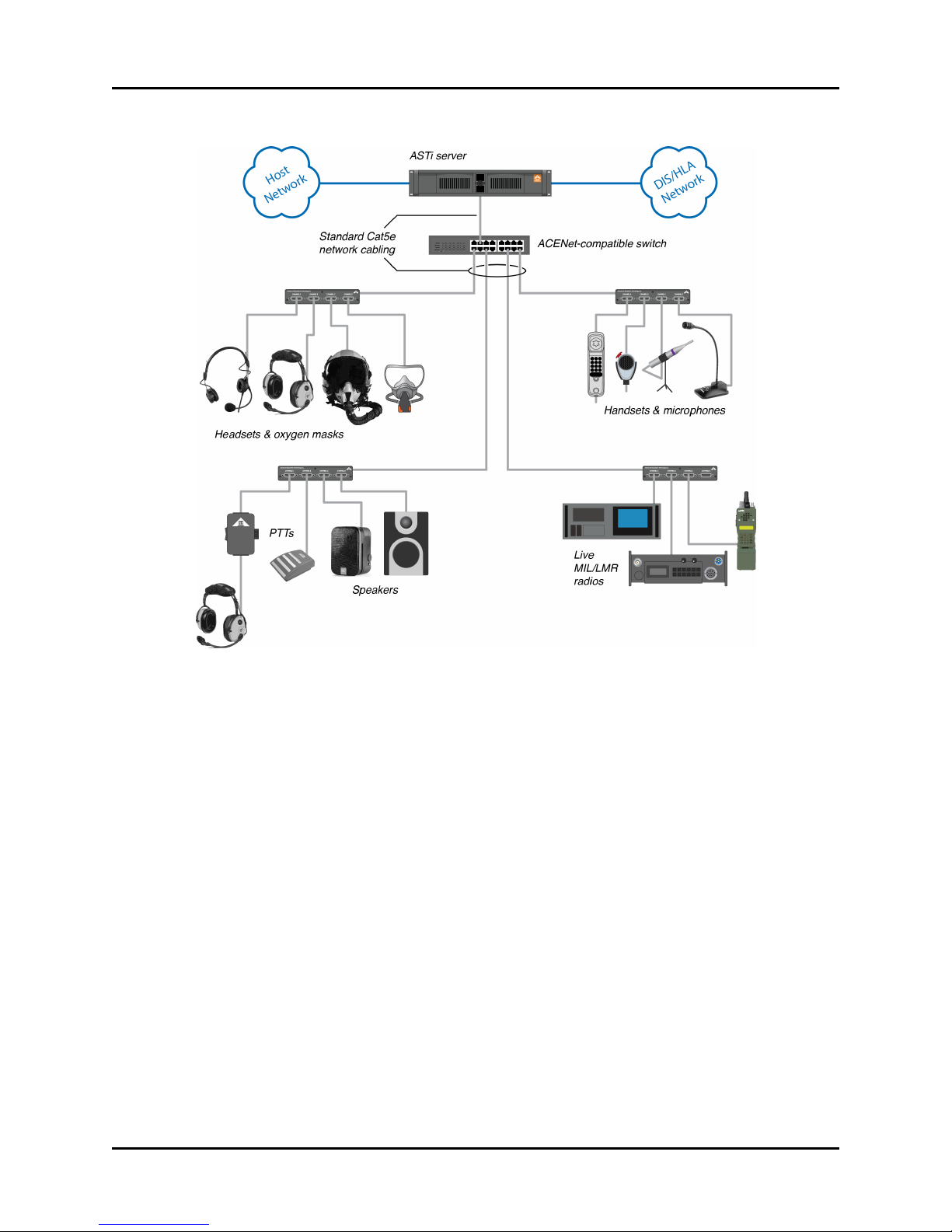
The following figure shows an example of an ACU2 hardware configuration:
Figure 1: ACU2 hardware configuration
2 Copyright © 2017 Advanced Simulation Technology inc.
Page 10
ACU2 Technical User Guide (Rev. L, Ver. 1)
2.0 Physical description
The following sections provide a physical description of the ACU2, including diagrams with
and without bezels, a list of specifications, and diagrams and descriptions of the front and rear
panels.
2.1 ACU2 with bezels
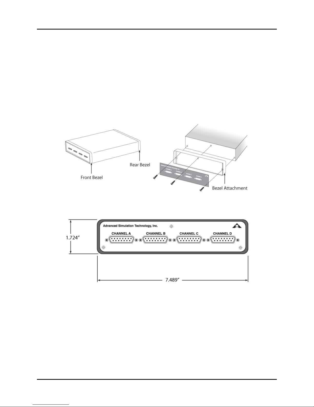
The ACU2 has two bezels, encompassing the front and rear panels. This ACU2 is Conformitè
Europèene (CE)/Restriction of Hazardous Substances (RoHS) certified. Removing the bezels
voids the CE certification. The following figure shows the ACU2 front bezel:
Figure 2: ACU2 front bezel
The following figure shows ACU2 height and width dimensions:
Figure 3: ACU2 height and width dimensions
Copyright © 2017 Advanced Simulation Technology inc. 3
Page 11
ACU2 Technical User Guide (Rev. L, Ver. 1)
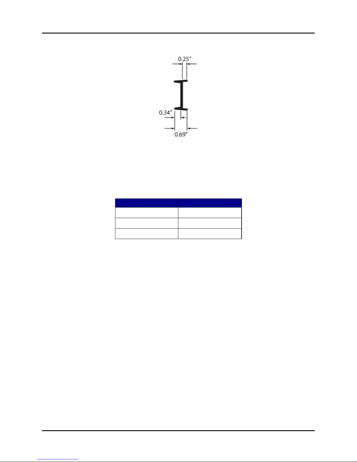
The following figure shows ACU2 bezel side dimensions:
Figure 4: ACU2 bezel side dimensions
2.2 ACU2 without bezels
Older versions of the ACU2 do not have bezels. The following table shows the specification for
ACU2s without bezels:
Specification Description
Length 7.5"
Width 7"
Height 1.55"
Table 1: Specifications for ACU2s without
bezels
2.3 Weight
A packaged ACU2 weighs 2 lbs. The power supply included with the ACU2 weighs 0.5 lbs.
4 Copyright © 2017 Advanced Simulation Technology inc.
Page 12
ACU2 Technical User Guide (Rev. L, Ver. 1)
2.4 Front panel
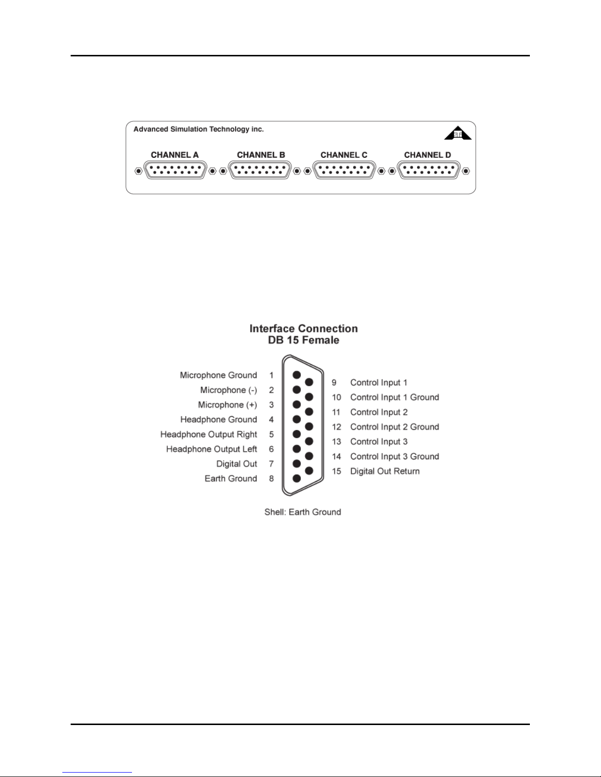
The following figure shows the ACU2's front panel:
Figure 5: Front panel of ACU2 without bezel
The front panel features four DB-15 connectors that are compatible with a variety of audio and
press-to-talk (PTT) devices.
2.4.1 Audio interface: DB-15 pinout
The following figure shows a DB-15 pinout for the ACU2 audio interface:
Copyright © 2017 Advanced Simulation Technology inc. 5
Figure 6: Interface connection DB-15 female
Page 13
ACU2 Technical User Guide (Rev. L, Ver. 1)
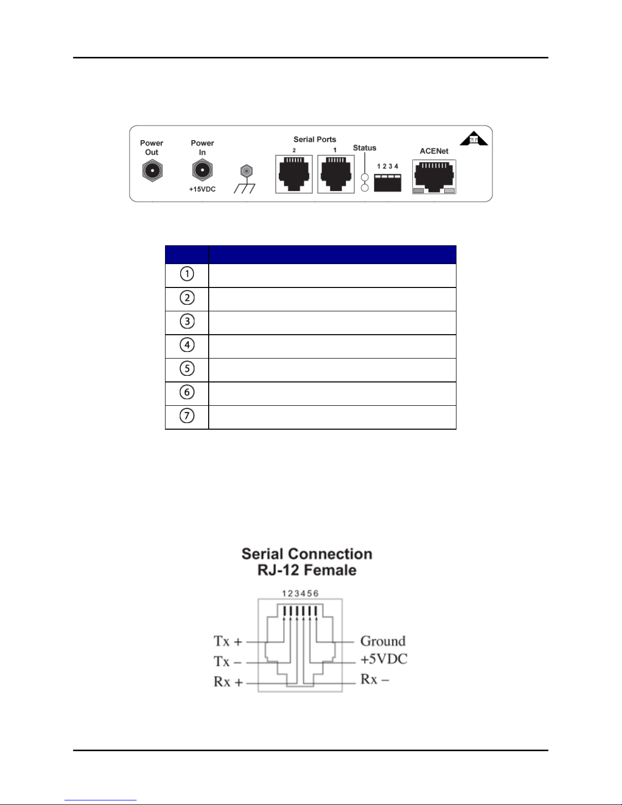
2.5 Rear panel
The following figure shows the ACU2 rear panel:
Figure 7: Rear panel of ACU2 without bezels
Number Description
Power Out: for use with the power daisy chain
Power In: for use with the ACU2 power supply, included
Earth grounds
Serial ports
Status indicator lights
Dual in-line package (DIP) switches
ACENet connection
Table 2: Rear panel callouts
2.5.1 Serial ports
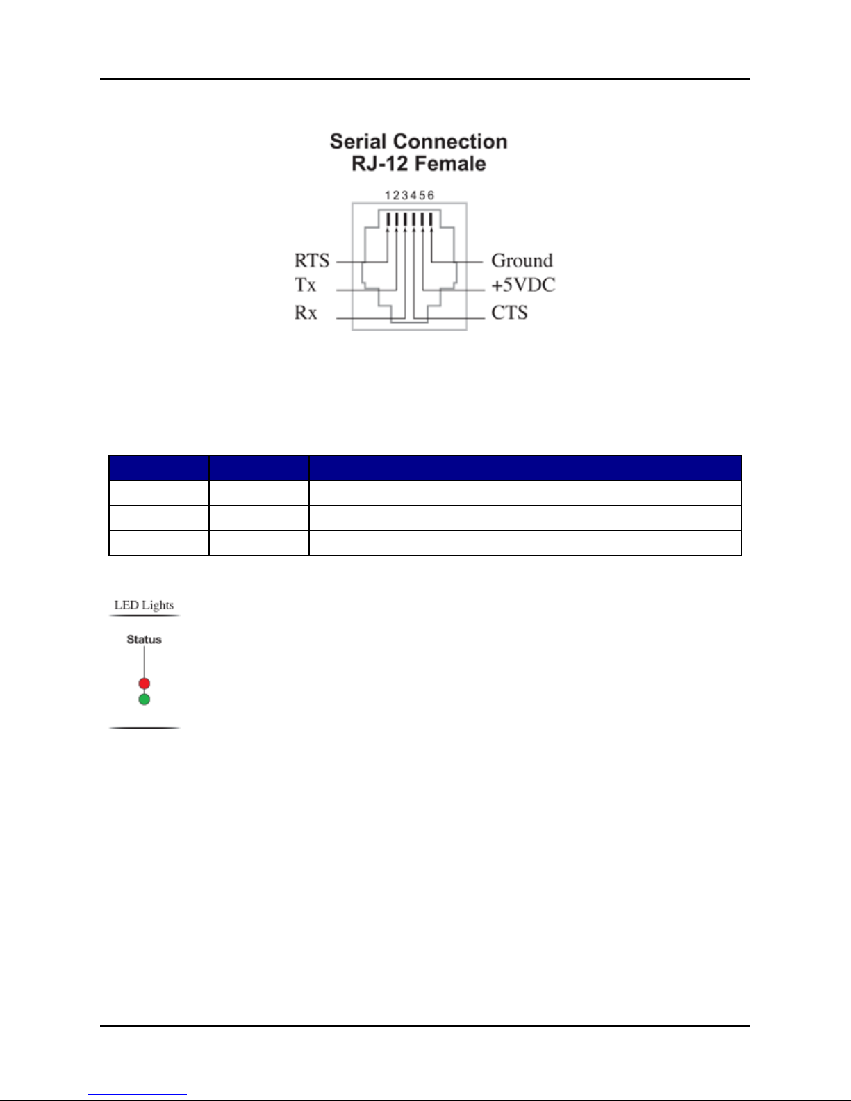
The ACU2 has two serial ports that provide a control interface for ASTi hand-held terminals
(HHTs), simulated panels, and live radio control. The following figure shows an RJ-12 female
serial connection in RS-422 mode:
6 Copyright © 2017 Advanced Simulation Technology inc.
Figure 8: RJ-12 pin out: RS-422 mode
Page 14
ACU2 Technical User Guide (Rev. L, Ver. 1)
The following figure shows an RJ-12 female serial connection in RS-232 mode:
Figure 9: RJ-12 pin out: RS-232 mode
2.5.2 Status indicator lights
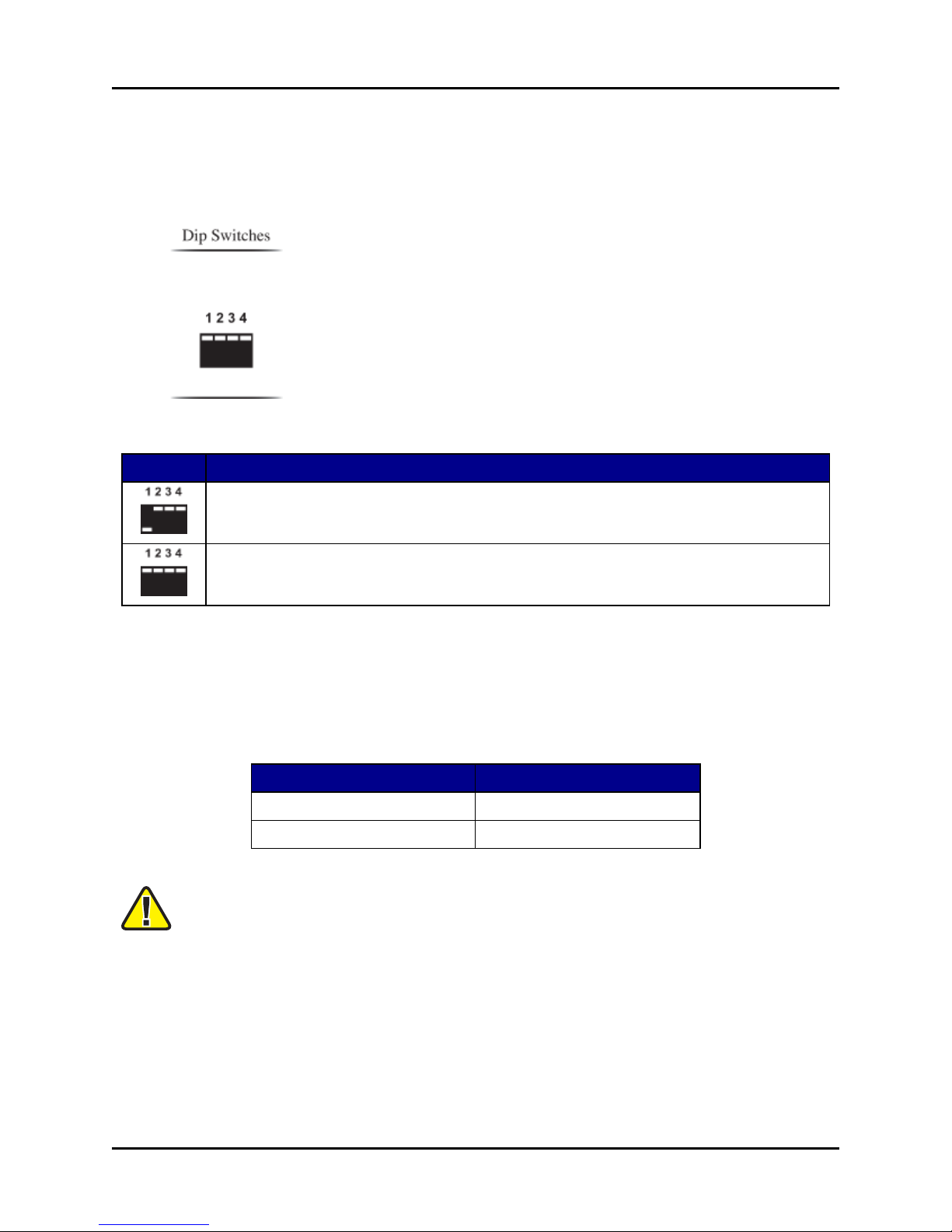
The ACU2 LED indicator lights display ACU2 status:
LED Lights
Flashing green Bottom Normal operation.
Solid green Bottom The ACU2 started up properly, but the ACENet is disconnected.
Red Top Internal board failure.
Location
Status
Table 3: Status indicator lights
Copyright © 2017 Advanced Simulation Technology inc. 7
Page 15
ACU2 Technical User Guide (Rev. L, Ver. 1)
2.5.3 DIP switch positions
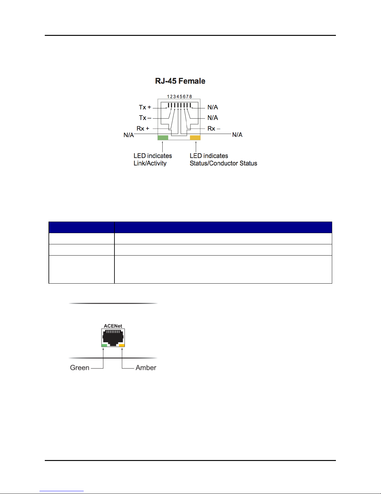
Dual in-line package (DIP) switches toggle between normal operation mode and firmware
update mode. For additional guidance, see Section 8.0, "Firmware updates" on page20.
The following figure shows DIP switch positions:
Position Status
Position 1 down allows for firmware updates.
Default position for normal operation.
Table 4: DIP switch positions
2.5.4 ACENet connection
The ACU2's ACENet port connects to an ACENet-compatible switch via a Category 5e
(CAT5e) cable or better.
Device Cable Length
ACU2 100 meters (328 feet)
Telestra or server 100 meters (328 feet)
Table 5: Maximum cable length to ACENet switch
Important: Customer-made cables are the primary reason for product failure. ASTi recom-
mends high-quality, manufactured CAT5e cables.
Alternatively, the ACU2 can connect directly to the Telestra or Voisus server using a crossover
cable. The ACU2 does not support daisy chaining to additional units or internal switching across
networks.
8 Copyright © 2017 Advanced Simulation Technology inc.
Page 16
ACU2 Technical User Guide (Rev. L, Ver. 1)
2.5.4.1 RJ-45 ACENet connection pinout
The following figure shows an RJ-45 ACENet connection pinout:
Figure 10: RJ-45 ACENet connection pin out
2.5.4.2 ACENet indicator lights
The ACENet LED indicator lights display the port status:
LED Light Status
Solid green Network link
Flashing green Network activity
Solid or flashing amber One ACENet device per network functions as the ACENet master and is iden-
tified with a flashing amber light. All other ACENet devices should report a solid
amber light.
Table 6: ACENet indicator lights
Copyright © 2017 Advanced Simulation Technology inc. 9
Page 17

ACU2 Technical User Guide (Rev. L, Ver. 1)
3.0 Audio input and audio output
The following sections describe ACU2 audio input and output specifications.
3.1 Audio input
The following table shows ACU2 audio input characteristics and values:
Input Impedance 4.6 k
Input Level 3.25 Vpp max (6.5 Vpp differential)
Input Gain -8 dB, +2 dB to +57 dB, software configurable
Note: The ACU2 gain covers a total range of 65 dB. Between +2 dB and +57 dB,
the gain can be set in 1 dB steps. A value of -8 dB is available for input signals
greater than line level. The range -8 dB to +2 dB cannot be selected as a function
of design.
Microphone Power +12.5 VDC, software-enabled
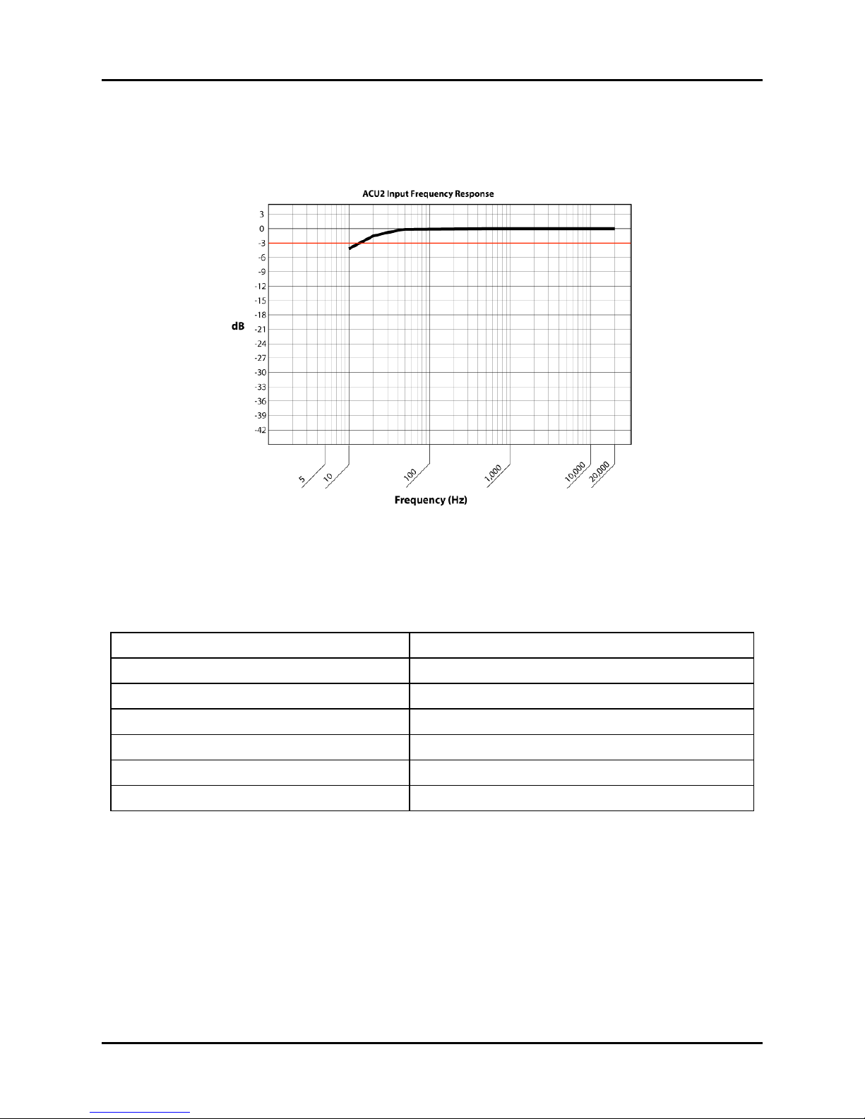
Frequency Response 20 Hz to 20 kHz, +/- 1.5 dB
Table 7: Audio input characteristics
10 Copyright © 2017 Advanced Simulation Technology inc.
Page 18
ACU2 Technical User Guide (Rev. L, Ver. 1)
3.1.1 Microphone power
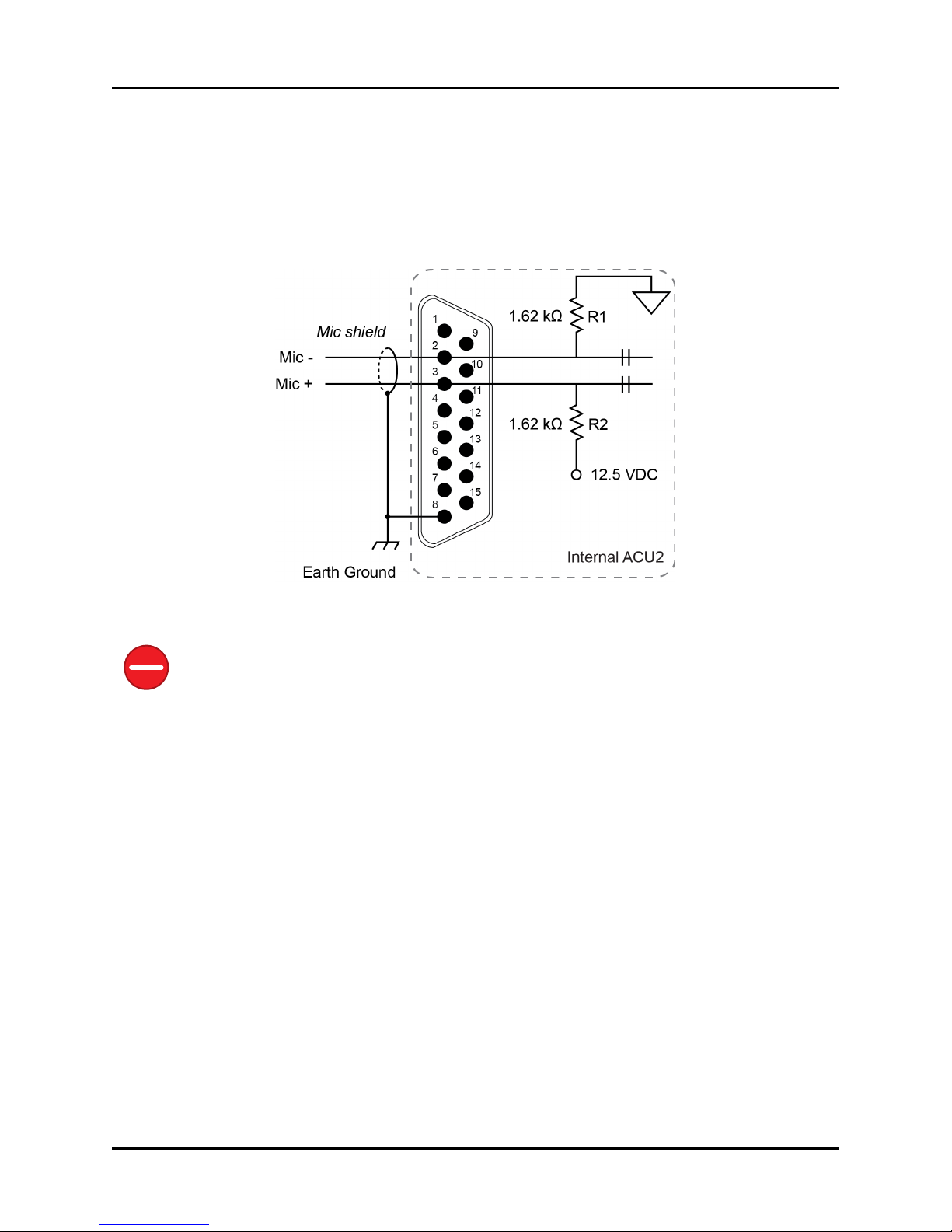
In Telestra systems, microphone power is configured in the Remote Management System
(RMS). Input levels can be adjusted in the RMS to accommodate line level signals as well as
microphone level signals. R1 and R2 connections are only active when power mode is enabled
in the software:
Figure 11: Microphone power diagram
Caution: Do not connect a microphone requiring phantom power to an ACU2 device, as this
will damage the microphone. If you are unsure of the difference between microphone power
and phantom power, contact the microphone manufacturer or ASTi before connecting equipment. Most military headsets use microphone power.
Copyright © 2017 Advanced Simulation Technology inc. 11
Page 19
ACU2 Technical User Guide (Rev. L, Ver. 1)
3.1.2 Input frequency response
The following figure shows an ACU2's input frequency response:
Figure 12: ACU2 input frequency response
3.2 Audio output
The following table shows an ACU2's audio output:
Output Impedance 10 Ohms
Output Current 0.201 A at 8 Ohms
Output Gain -25 dB to +10 dB
Output Level 1.61 VAC rms into 8 Ohms
Output Power 0.32 W at 8 Ohms
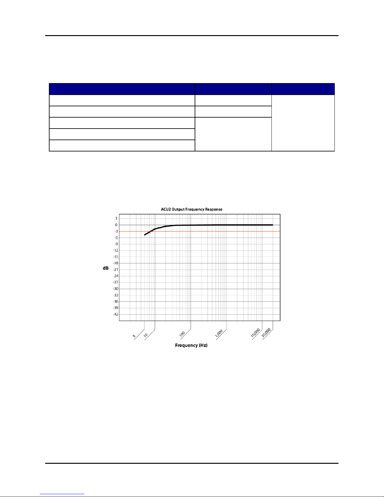
Frequency Response 20 Hz to 20 kHz
Max Output Signal 10 Vpp
Figure 13: ACU2 audio output
12 Copyright © 2017 Advanced Simulation Technology inc.
Page 20
ACU2 Technical User Guide (Rev. L, Ver. 1)
3.2.1 Audio isolation characteristics
The following table shows audio isolation characteristics:
Between Isolation Frequency
Ch. 1 left to Ch. 1 right output channels -81 dB at + 4 dBu 20 Hz to 20 kHz
Ch. 1 to Ch. 2 output channels -77 dB at +4 dBu
Ch. 1 output to Ch. 1 input > -100 dB at +4 dBu
Ch. 1 output to Ch. 2 input
Ch. 1 input to Ch. 2 input
Table 8: Audio isolation characteristics
3.2.2 Output frequency response
The following figure shows an ACU2's output frequency response:
Copyright © 2017 Advanced Simulation Technology inc. 13
Figure 14: ACU2 output frequency response
Page 21
ACU2 Technical User Guide (Rev. L, Ver. 1)
4.0 Control input and output
The following sections describe ACU2 control input and output specifications.
4.1 Control input
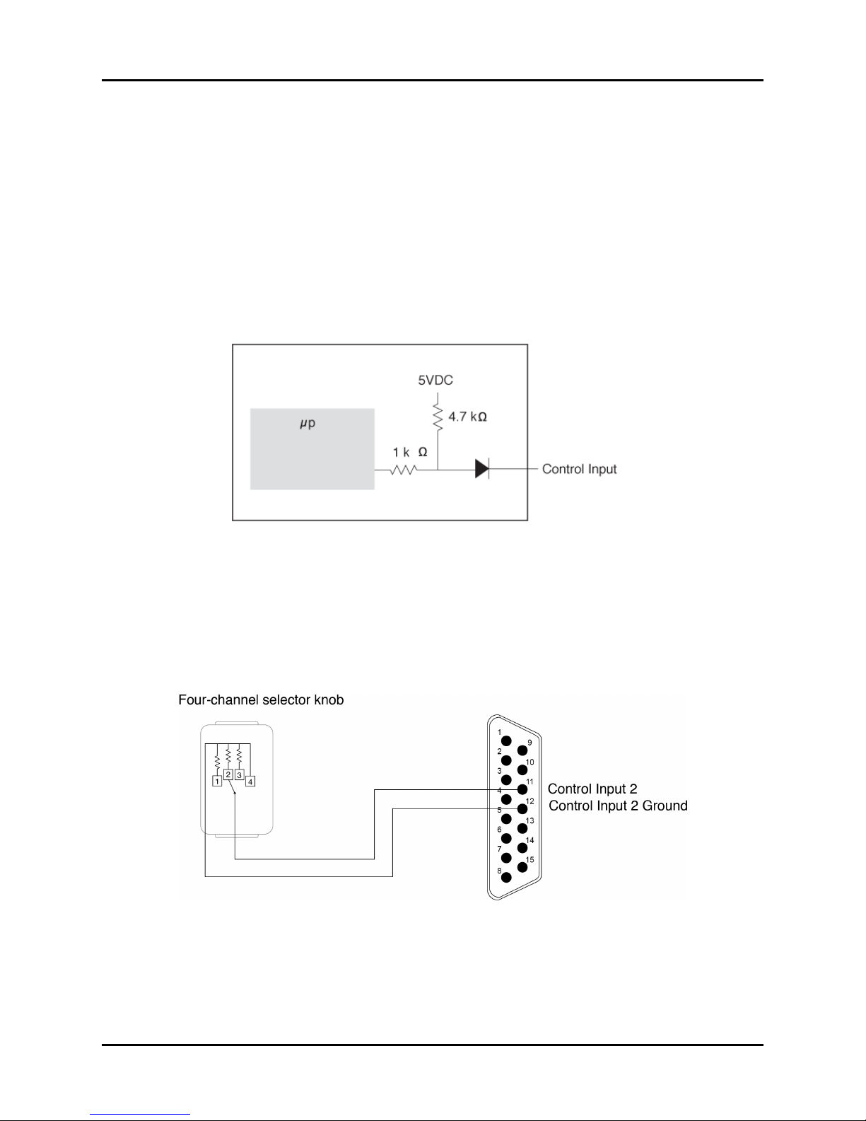
The control inputs are contact sensing; no voltage is required. Connect the control input and control input ground lines together using a switch or other suitable device, such as a press-to-talk
(PTT) device. The control input can function as a digital input or an analog input. In both cases,
the ACU2 component in the model will be able to read the control input value and use this value
as required for the application.
Figure 15: Control input timing diagram
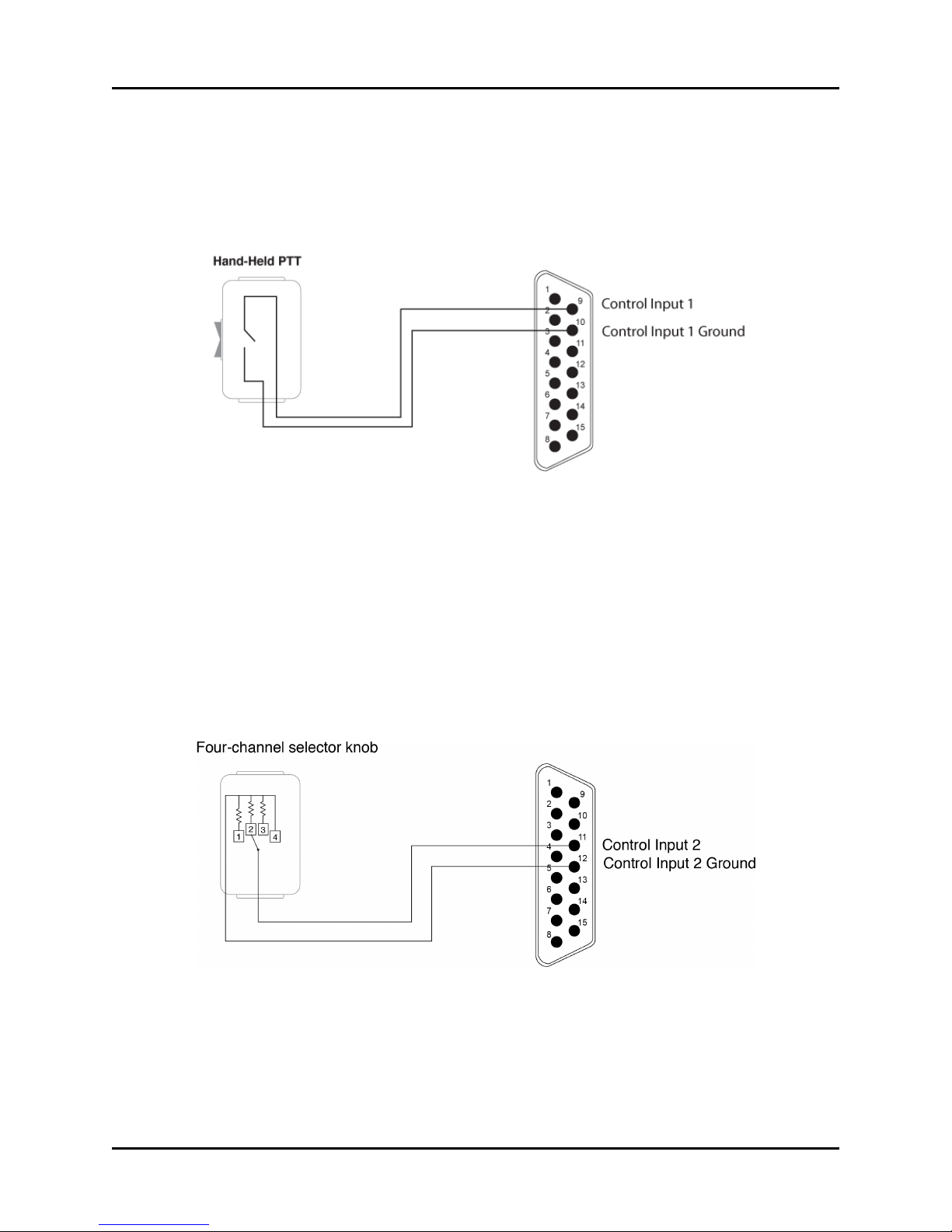
The control input can be used as an analog input by inserting a resistance between the control
input and control input ground pins. With this configuration, the ACU2 component in the model
maps the voltage to a uint8 value that you can use to model your application. For example, the
four-channel selector knob contains a switch that changes the resistance between the control
input and control input ground pins. The uint8 number read in the ACU2 software component
varies by a given percentage based on the tolerances of all the components involved.
Figure 16: Four-channel selector knob
14 Copyright © 2017 Advanced Simulation Technology inc.
Page 22
ACU2 Technical User Guide (Rev. L, Ver. 1)
4.1.1 Control input used as a digital input
To use the control input as a digital input, short or open the required pins. For example, if you
short pins 9 and 10, Control Input 1 is true. If the pins are open, Control Input 1 is false. In this
example, the control input acts like an on/off switch.
Figure 17: Digital In
4.1.2 Control input used as analog input
The control input can be used as an analog input by inserting a resistance between the control
input and control input ground pins. With this configuration the ACU2 component in the model
will map the voltage to an uint8 value that can be used in modeling your application. The fourchannel selector knob, for example, contains a switch that is used to change the resistance
between the control input and control input ground pins. The uint8 number read in the ACU2
software component will vary by a given percentage based on the tolerances of all of the components involved.
Figure 18: Analog In
Copyright © 2017 Advanced Simulation Technology inc. 15
Page 23
ACU2 Technical User Guide (Rev. L, Ver. 1)
4.2 Digital output
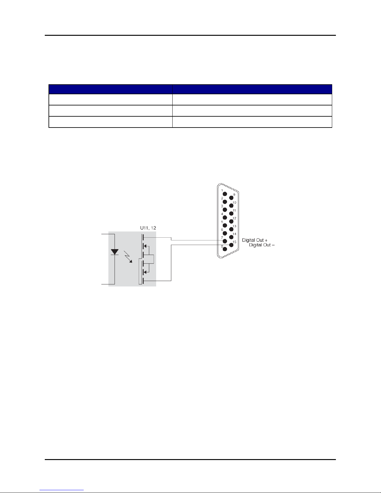
The digital output circuitry consists of an opto-isolated, solid-state relay for switching power to
external loads.
Type Opto-isolated Field-Effect Transistor (FET)
Maximum continuous current rating 120 mA
Maximum power dissipation 180 mW
Maximum frequency responses 500 Hz
Table 9: Digital output Opto-isolated FET values
4.2.1 Digital output circuitry
The following figure shows digital output circuitry:
Figure 19: Digital output circuitry
16 Copyright © 2017 Advanced Simulation Technology inc.
Page 24
ACU2 Technical User Guide (Rev. L, Ver. 1)
5.0 Typical headset connections
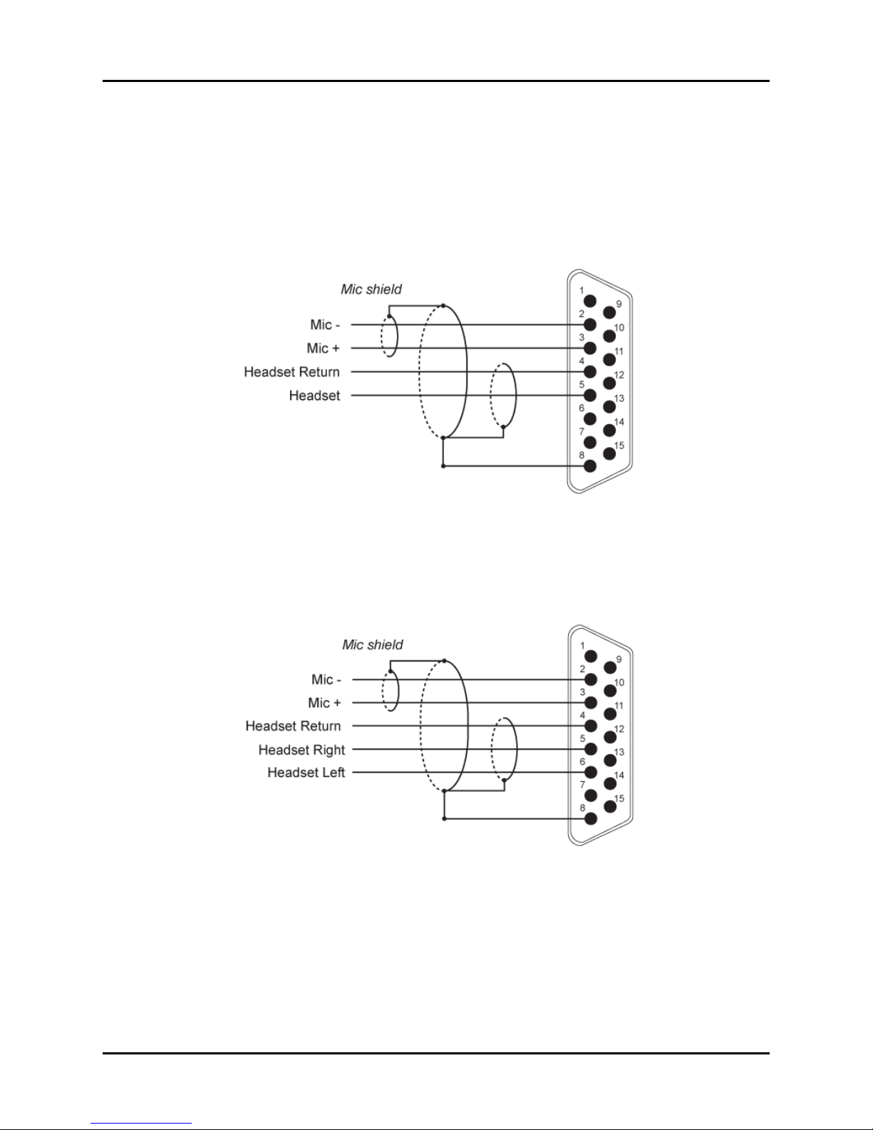
The following sections show diagrams for mono and stereo headset connections.
5.1 Mono headset connection
The following figure shows a mono headset connection:
Figure 20: Mono headset connection
5.2 Stereo headset connection
The following figure shows a stereo headset connection:
Figure 21: Stereo headset connection
Copyright © 2017 Advanced Simulation Technology inc. 17
Page 25

ACU2 Technical User Guide (Rev. L, Ver. 1)
6.0 Software configuration
For software configuration instructions, reference the following:
Name Description
Telestra See the Telestra Remote Management System User Guide on the Telestra Support page.
Voisus See “Voisus Hardware Clients” in the Voisus Client User Guide on the Voisus Support page.
Table 10: Software configuration
18 Copyright © 2017 Advanced Simulation Technology inc.
Page 26
ACU2 Technical User Guide (Rev. L, Ver. 1)
7.0 Earth ground
ASTi does not require the ACU2 to be grounded. However, it was designed to accommodate
customers with strict grounding policies and requirements. To reduce resistance, keep your
grounding wire as short as possible. This practice effectively dissipates an unwanted electrical
charge.
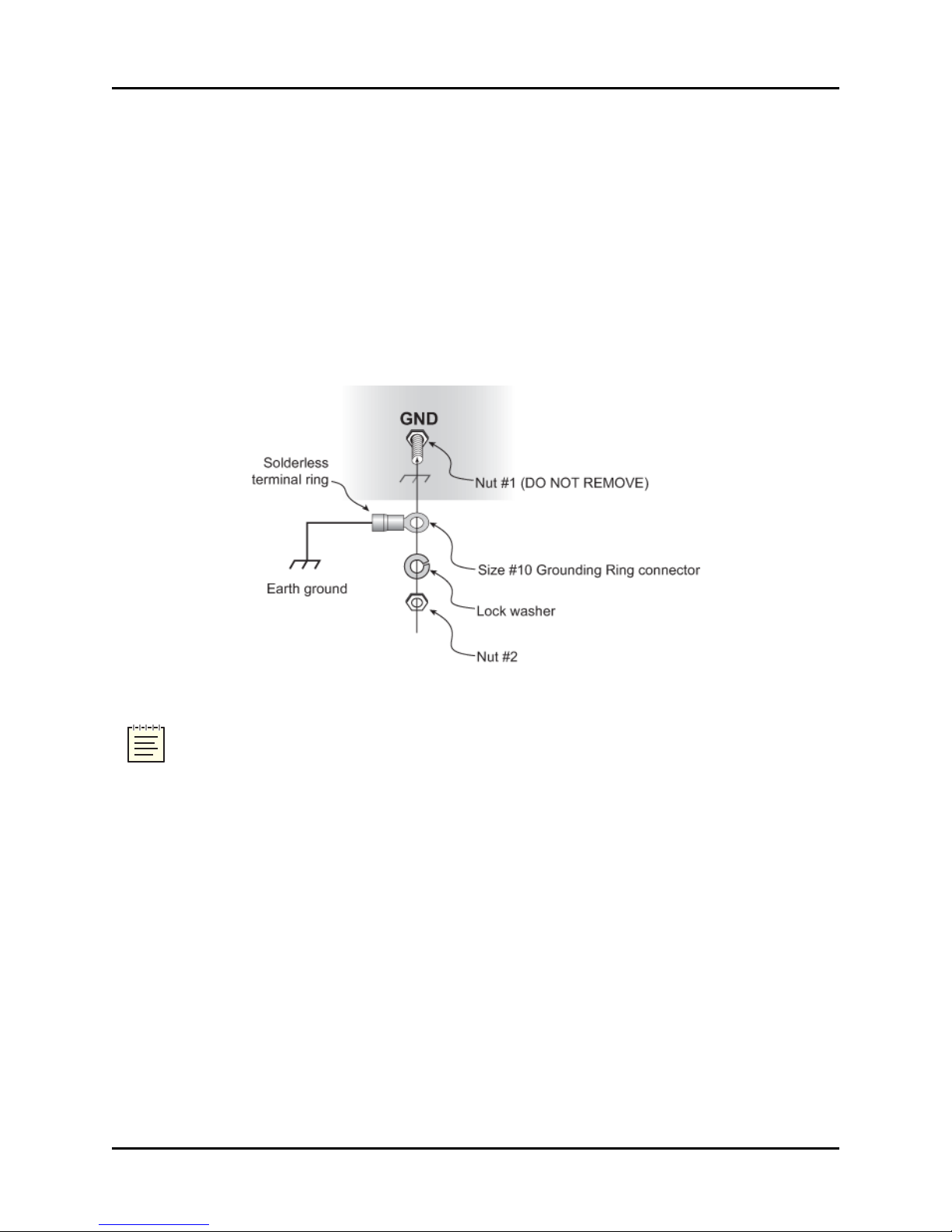
The following equipment is required:
l #10 grounding ring connector
l Ground wire (i.e., stranded, braided, or strap wire; 18 gauge American wire gauge
(AWG) minimum)
Figure 22: Grounding
Note: Do not remove nut #1 from the screw as it will cause the screw to fall inside the
ACU2 chassis.
To ground the ACU2, follow these steps:
1. Remove nut #2.
2. Slip the grounding ring connector onto the threaded end of the jackscrew.
3. Insert nut #2 onto the threaded end of the jack screw. Take care not to cross thread or
overtighten the nut when reattaching.
Copyright © 2017 Advanced Simulation Technology inc. 19
Page 27
ACU2 Technical User Guide (Rev. L, Ver. 1)
8.0 Firmware updates
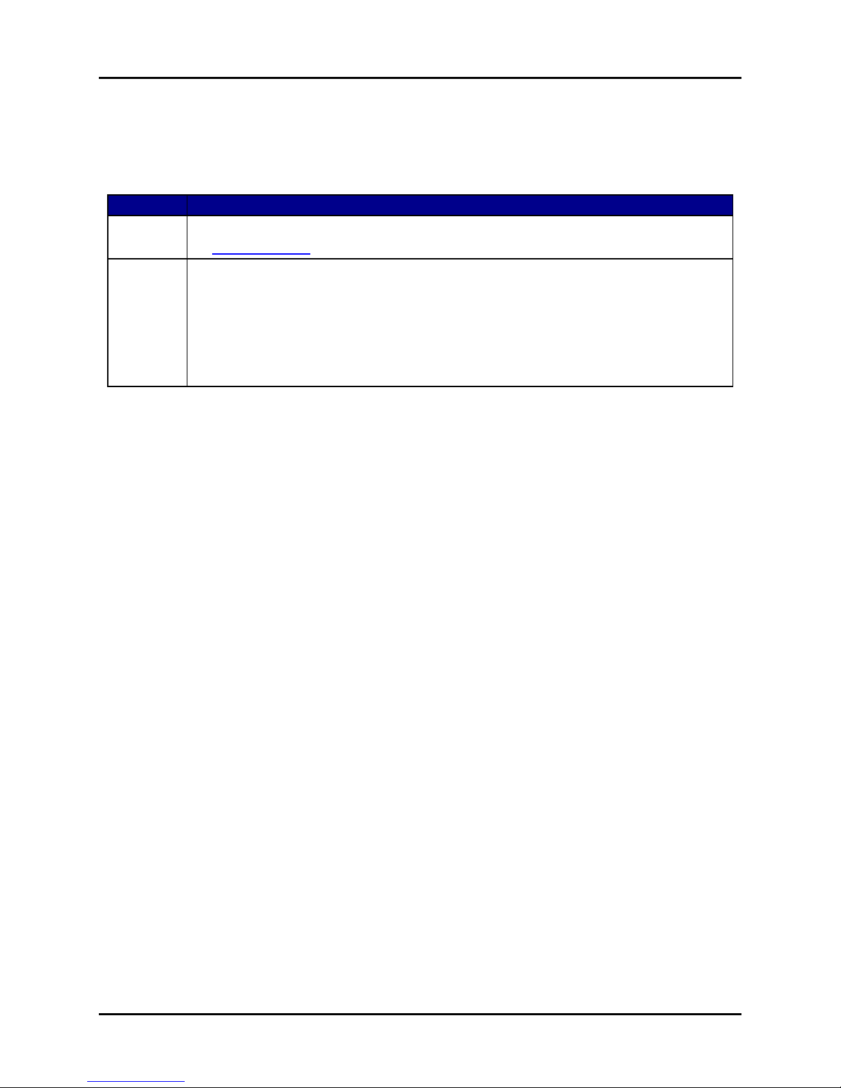
The following table provides ACU2 firmware update instructions for Telestra and Voisus software:
Update Instructions
Telestra To update ACU2 firmware, see the Telestra Remote Management System User Guide on
the Telestra Support page.
Voisus To update ACU2 firmware for Voisus, follow these steps:
1. In the Voisus web interface, from the top-right navigation bar, click Manage, and then
click Hardware Devices.
2. Click the ACU2 tab. A message displays if any connected ACU2s need a firmware
update.
3. To complete the procedure, follow the on-screen instructions.
Table 11: Software firmware updates
20 Copyright © 2017 Advanced Simulation Technology inc.
Page 28
ACU2 Technical User Guide (Rev. L, Ver. 1)
9.0 Rackmount ACU2s
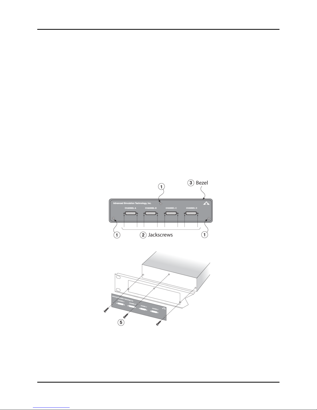
The available rackmounting bracket accommodates two ACU2s side by side and measures 1U
high and 19" wide. To install the rackmount, follow these steps:
1. Remove the two bottom corner screws and the top middle screw on the front of the
ACU2.
2. Use a nut driver (3/16") to remove the two jackscrews from each side of the four connectors.
3. Remove the faceplate with the white lettering and the bezel. Save the bezel for when you
remove the ACU2 from the rackmount.
4. Place the ACU2 into the backside of the rackmount. The rackmount fits in place of the
bezel.
5. Place the faceplate on the front side of the rackmount. Install the three black screws, starting with the top middle screw first for proper alignment.
6. Install the jackscrews on each side of the four connectors.
Copyright © 2017 Advanced Simulation Technology inc. 21
Figure 23: ACU2 rackmount installation
Page 29
ACU2 Technical User Guide (Rev. L, Ver. 1)
9.1 Power daisy chain
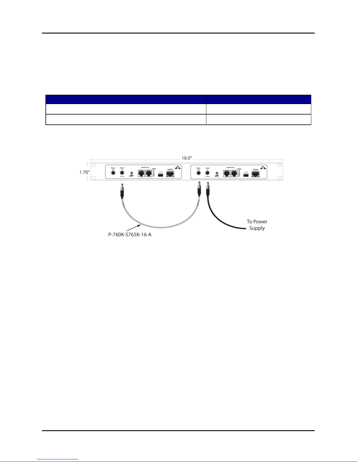
The power daisy chain connection enables operation of two rackmounted ACU2 units from a
single-power supply. Daisy chaining ACU2 power requires an upgraded power supply (model
number TR7 A15 from CINCON Electronic Co. LTD). Contact ASTi for details. The daisy
chain cable (P-760K-S765K-16-A) is included with the upgraded power supply.
Name Model/Part No.
Power In Connector (Black) Switchcraft 760K
Power Out Connector (Black) Switchcraft S765K
Table 12: Power daisy chain connections
The following figure shows power daisy chain connectors:
Figure 24: Power daisy chain connectors
22 Copyright © 2017 Advanced Simulation Technology inc.
Page 30
ACU2 Technical User Guide (Rev. L, Ver. 1)
10.0 Specifications
The following sections describe ACU2 power requirements, memory devices, temperature and
humidity ranges, and reliability.
10.1 Power requirements
The ACU2 is shipped with a standard power supply, which provides power to one ACU2. The
power supply should only be connected to a grounded outlet. To rackmount the ACU2s, you
may need to purchase an upgraded power daisy chain. For more information about the power
daisy chain, see Section 9.1, "Power daisy chain" on the previous page.
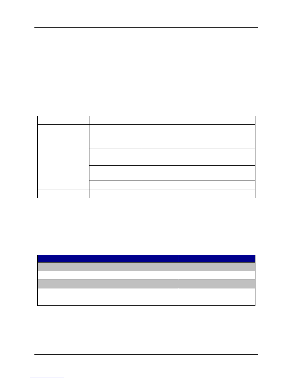
Input to PSL-UM-001 100–240 VAC, 50–60 Hz, 1.5 A
Power In Connector Inside Diameter 0.100", Outside Diameter 0.218", locking, center positive
Connector P/N: Switchcraft 712RA supplied with P2439 Hex Nut
(5/16–32) and P2441 Washer
Mating Connector P/N: Switchcraft 760k
Power Out Connector Inside Diameter 0.080", Outside Diameter 0.218", locking, center positive
Connector P/N: Switchcraft 722RA supplied with P2439 Hex Nut
(5/16–32) and P2441 Washer
Mating Connector P/N: Switchcraft S765k
Power Consumption +15 VDC, 2A (plug-in AC/DC converter supplied with each unit)
, (120 VAC), 0.75 A
RMS
RMS
(240 VAC)
The power adapter inlet connector is an IEC 320 type C14 or C8, requiring a matching cord set
equipped with an IEC 320 C13 or C7 connector (i.e., female line cord). Country-specific power
connectors must be acquired separately for international use.
10.2 Memory devices
The ACU2 memory devices are summarized in the table below:
Name Memory
Volatile memory
MCU Internal SRAM 69 kb
Non-volatile memory
MCU Internal 256 kb
Flash 8 Mb
The ACU2 does not contain media storage capability (i.e., removable or non-removable disk
drives, tape drives, memory cards, etc.).
Copyright © 2017 Advanced Simulation Technology inc. 23
Table 13: ACU2 memory devices
Page 31
ACU2 Technical User Guide (Rev. L, Ver. 1)
10.3 Temperature and humidity ranges
The following table shows ACU2 temperature and humidity ranges:
Type Suggested Range
Operating Temperature Range +10°C to 32°C (50°F to 90°F)
Operating Max. Temperature Gradient 20°C (68°F) per hour
Operating Humidity Range 10% to 70% non-condensing
Storage Temperature Range 0°C to 55°C (32°F to 135°F)
Storage Max. Temperature Gradient 30°C (86°F) per hour
Storage Humidity Range 5% to 95%
Table 14: Temperature and humidity ranges
10.4 Reliability
The following table shows an ACU2's typical Mean Time Between Failure (MTBF) rate for
commercial off-the-shelf (COTS) and military (MIL) systems:
Category MTBF Rate
COTS 108,100.75 hours
MIL 48, 390.23 hours
Table 15: ACU2 MTBF rates
24 Copyright © 2017 Advanced Simulation Technology inc.
Page 32

ACU2 Technical User Guide (Rev. L, Ver. 1)
11.0 Warranty information
ASTi covers the equipment by warranty for one year following purchase. For equipment
upgrades, the warranty applies to the upgraded component's original shipment date. Unless otherwise stated, ASTi also covers other provided or purchased commercial equipment (e.g., monitors, amplifiers, speakers, and fiber optic links).
The warranty does not cover improper equipment handling or improperly packaged returns.
Extended warranties are available. Contact ASTi for details at (703) 471-2104.
11.1 Repairs and returns
To return equipment to ASTi, observe the following:
1. Request a Return Material Authorization (RMA) number through the form at rma.asti-
usa.com/rma. ASTi's Production department cannot receive a repair without an RMA
number. The shipping label must also include the RMA number. Any items received from
customers without RMA numbers or appropriate contact information will not be tested.
After 60 days, ASTi reserves the right to scrap all hardware received in this condition.
2. When packaging the equipment in question, make sure it is well-protected. Failure to properly package the equipment during shipping could void the warranty.
a. Always double-box the device.
b. The inner container should employ some semi-rigid, contour-fitting foam, while the
exterior container should use a more pliant, shock-absorbing material, such as styrofoam peanuts.
c. To prevent possible Electrostatic Discharge (ESD) damage, properly enclose the
device in an antistatic bag.
3. Do not send accessory pieces, such as rack mount kits, power supplies, or software. Only
include items that do not work.
4. Include a description of the problem, including the serial number for the unit in question.
Include point of contact information, including a name, telephone number, and equipment
return address. Failure to include this information could extensively delay the return of
equipment.
5. If you are an international customer, include the correct product value on all shipping documents. For proper harmonized tariff codes, contact ASTi. The customer is responsible
for duties, taxes, and fees incurred during shipment.
ASTi evaluates equipment free of charge and does not begin work without prior customer
approval.
Copyright © 2017 Advanced Simulation Technology inc. 25
Page 33

ACU2 Technical User Guide (Rev. L, Ver. 1)
The customer is responsible for shipping charges to ASTi for warranty and non-warranty
repairs. If equipment is not under warranty, a purchase order is required to cover any repairs.
ASTi will provide a quote for all non-warranty items, including return shipping. The customer is
responsible for return shipping charges on non-warranty equipment. ASTi ships equipment still
under warranty back to the customer via FedEx, unless otherwise directed. ASTi is responsible
for return shipping charges on domestic items under warranty.
If ASTi does not receive the equipment 30 days after the RMA was issued, ASTi closes the
RMA and designates it as unused.
26 Copyright © 2017 Advanced Simulation Technology inc.
 Loading...