

Page 1
Contents
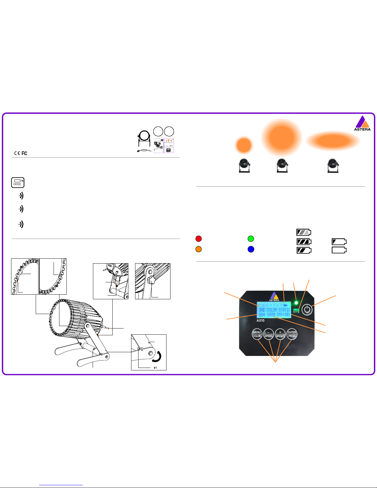
Control Panel
Battery Icon & Status LED
Key Functions
Controlling the SpotMax™
Set a color or basic eect through the control pad on the AX10’s backside. Press the MENU/COLOR button and use the + and – buttons to display
dierent colors. Conrm with the ENTER button. Press the ENTER/PROG button and use the + and – button to display dierent programs. Conrm
with ENTER button.
Use Astera’s ARC1 remote control, point at individual lights and press the desired eect. Note that the IR sensor is on the AX10 rearside although
the IR signal should bounce of walls and oor.
Astera’s remote control and the AsteraTouch tablet can group several lights together, address individual lights or groups of lights and send
complex eects to all lights in range. For additional information refer to the manual and quick start guide of ARC2 and ARC6 at
www.astera-led.com/downloads.
Connect an ART3 (Wireless DMX Transmitter) to your DMX desk to send wireless DMX signals to the AX10. You can set the AX10s DMX address
on its control pad or send it from a remote control. Additionally, the AX10 can be controlled by CRMX Wireless DMX (from Lumen Radio) and
W-DMX (from Wireless Solutions). For additional information refer to the ART3 manual at www.astera-led.com/downloads
RF
IR
DMX
Set Number
Group Number
DMX Address
Current Eect
IR Sensor
On/O
Control Pad
See Legend on Reverse
80%+
50% - 80%
15% - 50%
Less than 15%
The Battery Status LED is designed for being used before an event. All xtures should have a green Status LED to ensure that the battery lasts for your upcoming
event. If it is another color, recharging is recommended.
While the battery is charging the Status LED will be blue. Also, the Battery Icon will start the charging sequence. Once the battery is fully charged the battery icon
on the display will show all 3 bars (as below). If the battery is already fully charged and the power cord is plugged in, the display will show a battery with moving
bars for approx. 30-60 seconds after which it will stop and the icon will show a full battery. When the SpotMax™ is turned o and the power cord is connected, the
charging process will begin. This is indicated by the LCD display turning on.
The legs of the SpotMax™ have a U-shaped
enclosure to rest the leg latch into so that
when closed, the legs remain together, and
when open, the legs remain open. When the
legs are closed, the SpotMax™ can be
carried by hand and/or placed neatly into a
transportation case.
Perfect Spot
Beam: 13°
(without diusor)
Wallwash
Beam: 17° x 46°
(WALLWASH diusor)
Contents
Control Panel
Battery Icon & Status LED
Key Functions
Controlling the SpotMax™
Set a color or basic eect through the control pad on the AX10’s backside. Press the MENU/COLOR button and use the + and – buttons to
display dierent colors. Conrm with the ENTER button. Press the ENTER/PROG button and use the + and – button to display dierent p
rograms. Conrm with ENTER button.
Use Astera’s ARC1 remote control, point at individual lights and press the desired eect. Note that the IR sensor is on the AX10 rearside
although the IR signal should bounce of walls and oor.
Astera’s remote control and the AsteraTouch tablet can group several lights together, address individual lights or groups of lights and
send complex eects to all lights in range. For additional information refer to the manual and quick start guide of ARC2 and ARC6 at
www.astera-led.com/downloads.
Connect an ART3 (Wireless DMX Transmitter) to your DMX desk to send wireless DMX signals to the AX10. You can set the AX10s DMX
address on its control pad or send it from a remote control. For additional information refer to the ART3 manual at
www.astera-led.com/downloads.
RF
IR
DMX
Set Number
Group Number
DMX Address
Current Eect
IR Sensor
On/O
Control Pad
See Legend on Reverse
Full
70%
30%
Empty
The Battery Status LED is designed for being used before an event. All xtures should have a green Status LED to ensure that the battery lasts for your upcoming
event. If it is another color, recharging is recommended.
While the battery is charging the Status LED will be blue. Also, the Battery Icon will start the charging sequence. Once the battery is fully charged the battery icon
on the display will show all 3 bars while the power cord is connected. When the battery is fully charged, there will be 3 charging bars on the battery icon (as below).
If the battery is already fully charged and the power cord is plugged in, the display will show a ashing battery icon for approx. 30-60 seconds after which ashing
will stop and the icon will show 3 charging bars. When the SpotMax™ is turned o and the power cord is connected, the charging process will begin. This is
indicated by the LCD display turning on and the battery icon in the top right corner ashing. When the power cord is disconnected the battery symbol disappears.
The legs of the SpotMax™ have a U-shaped
enclosure to rest the leg latch into so that
when closed, the legs remain together, and
when open, the legs remain open. The legs
also contain a hole to attach a truss clamp.
13° Spot
(without diusor)
Wall Wash
(diusor sheet)
Contents
Control Panel
Battery Icon & Status LED
Key Functions
Controlling the SpotMax™
Set a color or basic eect through the control pad on the AX10’s backside. Press the MENU/COLOR button and use the + and – buttons to
display dierent colors. Conrm with the ENTER button. Press the ENTER/PROG button and use the + and – button to display dierent p
rograms. Conrm with ENTER button.
Use Astera’s ARC1 remote control, point at individual lights and press the desired eect. Note that the IR sensor is on the AX10 rearside
although the IR signal should bounce of walls and oor.
Astera’s remote control and the AsteraTouch tablet can group several lights together, address individual lights or groups of lights and
send complex eects to all lights in range. For additional information refer to the manual and quick start guide of ARC2 and ARC6 at
www.astera-led.com/downloads.
Connect an ART3 (Wireless DMX Transmitter) to your DMX desk to send wireless DMX signals to the AX10. You can set the AX10s DMX
address on its control pad or send it from a remote control. For additional information refer to the ART3 manual at
www.astera-led.com/downloads.
RF
IR
W-DMX
Set Number
Group Number
DMX Address
Current Eect
IR Sensor
On/O
Control Pad
See Legend on Reverse
Full
70%
30%
Empty
The Battery Status LED is designed for being used before an event. All xtures should have a green Status LED to ensure that the battery lasts for your upcoming
event. If it is another color, recharging is recommended.
While the battery is charging the green Status LED will be ashing on and o. Also, the Battery Icon will start the charging sequence. Once the battery is fully
charged the battery icon on the display will show all 3 bars while the power cord is connected. When the battery is fully charged, there will be 3 charging bars on
the battery icon (as below). If the battery is already fully charged and the power cord is plugged in, the display will show a ashing battery icon for approx. 30-60
seconds after which ashing will stop and the icon will show 3 charging bars. When the SpotMax™ is turned o and the power cord is connected, the charging
process will begin. This is indicated by the LCD display turning on and the battery icon in the top right corner ashing. When the power cord is disconnected the
battery symbol disappears.
The legs of the SpotMax™ have a U-shaped
enclosure to rest the leg latch into so that
when closed, the legs remain together, and
when open, the legs remain open. The legs
also contain a hole to attach a truss clamp.
13° Spot
(without diusor)
Wall Wash
(diusor sheet)
Contents
What the display indicates
Battery Icon & Status LED
Key Functions
Controlling the SpotMax™
SpotMax
2x Diusors
Power Cord
Manual
Battery
Icon & LED
Less than 30mins runtime
remaining; recharge
Over 30mins runtime have
been used
Up to 30mins runtime have
been used
Charging
RF Antenna
Hole for Clamp
Diusor Slot
Diusor Clip
Power In
Power Out
Leg Latch
ATTACH
The Diusor must be placed into
the Diusor Slot, then pressed
down so that Diusor Clip will
keep it in place.
REMOVE
The Diusor Clip should be pressed
in, and the Diusor Sheet should be
lifted out via the thumb hole.
Wide Angle
(30° diusor)
Diffusors
SpotMax
2x Diusors
Power Cord
Manual
Battery
Icon & LED
Less than 30mins runtime
remaining; recharge
Over 30mins runtime have
been used
Up to 30mins runtime have
been used
Connected to AC
RF Antenna
Hole for Clamp
Diusor Slots
Diusor Clip
Power In
Power Out
Leg Latch
ATTACH
The Diusor must be slid into
the Diusor Slots, then pressed
down and clipped in under the
Diusor Clip.
REMOVE
The Diusor Clip should be pressed
in, and the Diusor Sheet should be
lifted out via the thumb hole.
Wide Angle
(30° diusor)
Diffusors
SpotMax™
AX10
USER MANUAL
Manual Version: 1.0
Date of Issue: 30/01/14
Thumb
Hole
U-Shaped
Enclosure
315°
-SpotMax™
-2x Diusors
-Powercon True1
Power Cord
-User Manual
Battery
Icon & LED
Less than 30mins runtime
remaining; recharge
Over 30mins runtime have
been used
Up to 30mins runtime have
been used
Connected to AC
RF Antenna
Diusor Slots
Diusor Clip
Power In
Power Out
Leg Latch
ATTA CH
The Diusor must be slid into
the Diusor Slots, then pressed
down rmly and clipped in under
the Diusor Clip.
REMOVE
The Diusor Clip should be pressed
in, and the Diusor Sheet should be
lifted out via the thumb hole.
Flood
Beam: 32°
(FLOOD diusor)
Diffusors
SpotMax™
Thumb
Hole
U-Shaped
Enclosure
315°
Charging
Due to the Powercon True1 cord,
the SpotMax™ is IP65 waterproof,
even when charging. Ensure the
rubber caps are closed when not
charging to make it waterproof.
Tightener
Turn clock-wise to tighten the
legs of the SpotMax™.
Hole for Clamp
NOTE:
Each diusor has its
name inscribed on
the edge.
For ideal illumination
the text on the facia
should be facing outwards.
AX10
USER MANUAL
Manual Version: 1.0
Date of Issue: 30/01/14
Page 2
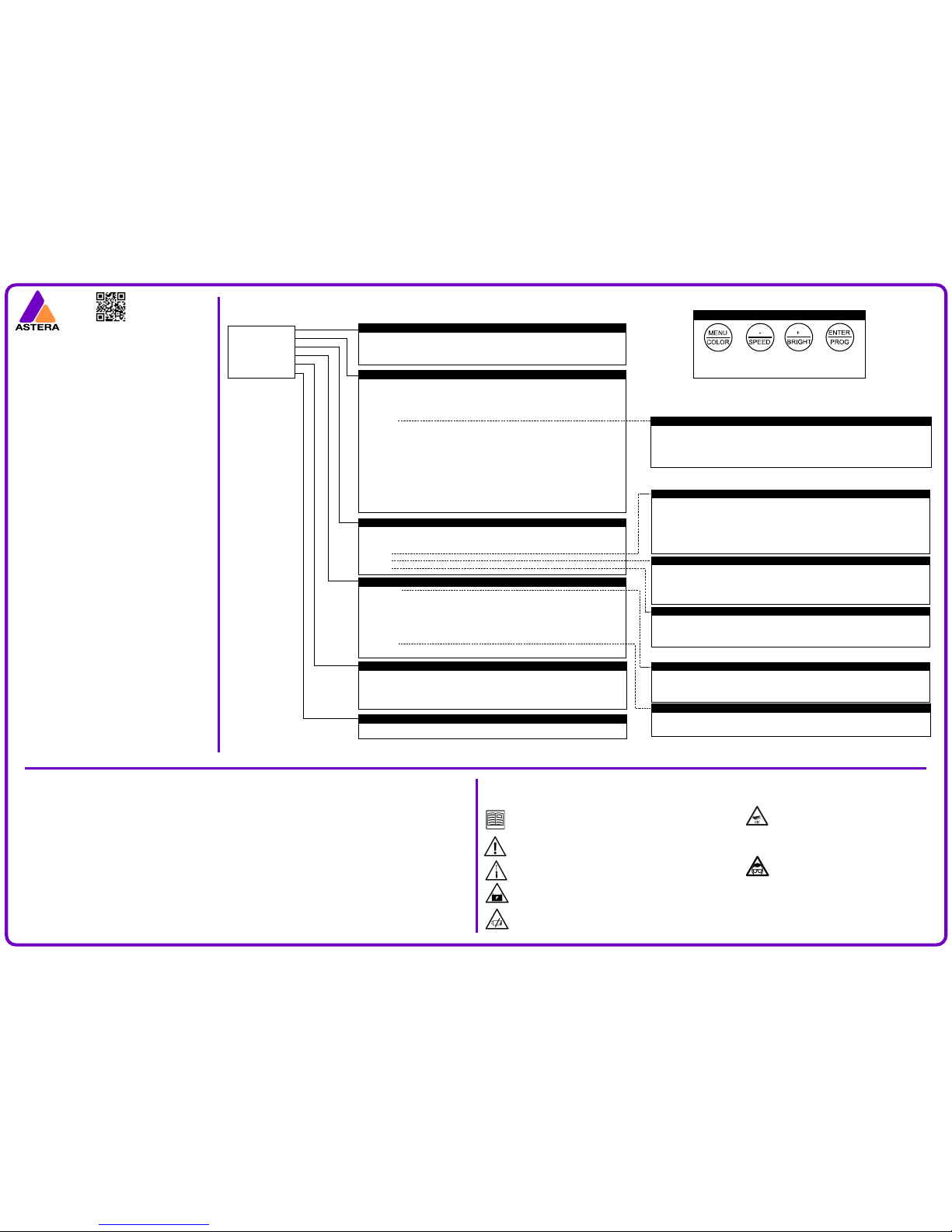
LEGEND
BACK TO SCROLL SCROLL CHOOSE/
PREVIOUS MENU DOWN UP CONFIRM
Safety
Before you operate this unit, read the manual carefully. Always make sure to include
the manual if you pass/rent/sell the unit to another user. Keep in mind that this
manual cannot address all possible dangers and environments. Please use your own
caution when operating.
Do not operate the unit in areas of temperature conditions or under direct sunlight.
It will cause abnormal function or damage the product.
Only qualied personnel may repair this product. Do not open the product housing.
A rechargeable battery is built into this unit. Please avoid bumping or plunging, it will
cause FIRE or EXPLOSION. Never store the battery when fully drained. Always recharge
immediately when empty.
Make sure to fully charge all units before storing them. Partially charged batteries will
lose capacity. Do not store the unit longer than 3 months without re-charging.
Troubleshooting
Technical Data
The SpotMax™ contains 9 RGBAW Philips LEDs, each containing
15W of LED power, totalling an impressive 135W LED power.
Illuminants: 9 x 15W RGBAW Philips LEDs
Total LED Power: 135W
Light Output: 3,350 lm at 4000K
typical values 3,150 lm at 6500K
3,100 lm at 7500K
Luminous Emittance: 10,350 lx at 2m
typical values 4,700 lx at 3m
1,800 lx at 5m
CRI: 92 at 3000K
(60%-70% intensity)
typical value
Strobe: 0-25Hz
Beam Angle: 13°
(achieved through Khatod lenses)
Battery: Built-in Samsung battery
Battery Lifetime: 70% capacity after 300 full
charging cycles
Battery Runtime: 5-20 hours
LED Lifetime: 50,000 hours
Working Voltage: Input 110-240V, 50/60Hz
Power Consumption: 170W
(maximum)
Wireless Module: 868MHz (US: 902-928MHz)
2.4GHz wireless module
Range: 300m / 330yds
(maximum)
DMX Capable: CRMX Wireless DMX (Lumen Radio)
W-DMX (Wireless Solutions),
or Wireless DMX (with ART3)
Connector: Neutrik Powercon True1 In/Out
Housing: Water-resistant cast aluminium
IP Rating: IP65
Relative Humidity: 0-100%
(non-condensing)
Operating Temperature: 0°-40°C (32°-104°F)
Weight: 8.15kg (18lbs)
Dimensions: L279mm x H296mm x W253mm
L10.9” x H11.6” x W9.9”
Environment: Indoor / Outdoor
Features: TruColor™ Calibration, Temperature
compensation, Dynamic
power-boost, Auto-white &
Auto-amber, Dual antennas.
Included Accessories: Power Cord, 2 x Diusor Sheets
Also Available: Charging Case
(holds 4)
Menu Structure
INPUT SELECT
AUTO SETTING
DMX SETTINGS
GENERAL SETTINGS
INFO
FACTORY RESET
GENERAL SETTINGS
LED POWER
BELONGS TO SET# Assigns the light to 1 of 255 sets so they can be easily targeted
WHITE CORRECTION Turns the white correction on/o
WHITE CALIB RED Adds or reduces the amount of red when displaying white light
WHITE CALIB GREE Adds or reduces the amount of green when displaying white light
WHITE CALIB BLUE Adds or reduces the amount of blue when displaying white light
RADIO PIN Assigns a unique frequency to ensure uninterrupted use when other controllers are present
AC FAILURE
CONTRAST Sets the contrast of the display beween 1 and 48
The xture does not start up.
It might be empty. Connect it to the AC power and try again.
The xture starts up and the display is on but the LEDs do not emit light.
The light is probably set to BLACKOUT mode or set to display black color. Use a remote control to change the color. If this does not work, do a factory reset.
The units behave incorrectly and do not display the color or eect I would like them to.
The xture might still have a setting which was previously programmed. Do a factory reset to completely wipe all settings.
I did a factory reset and still cannot control the light.
Make sure the RADIO PIN of the xture and controller are the same.
The units run out of battery after less than 8 hours.
To get a longer battery runtime, you can set the POWER MODE from HIGH BRIGHTNESS to NORMAL. Or you can program the xture to display colors
that take less power such as Red, Green, and Blue.
The power cable is connected but the xture is not charging.
To protect your battery, the xture will only charge if it is has a temperature of 45 degrees or less. Switch o the xture and the light will cool down.
DMX SETTINGS
DMX ADDRESS Sets the DMX address
CHANNELS Sets the amount of channels that are used to control one unit. One RGB channel
means that all LEDs have the same color
DMX TAB
STROBE
DMX FAIL
AUTO SETTINGS
PROGRAM Chooses one of 20 pre-dened programs that can be customized by colors, intensity, power
scheme, speed, fade, directions etc.
INTENSITY Sets the brightness of the LEDs
SPEED Sets the speed of the programs’ eects
FADE Sets the fade between the program eect steps
DIRECTION
CHASER Sets dierent color chasers
CHASER SPEED Sets the speed of the color chaser
GROUPS Assigns the light to 1 of 4 groups so they can be easily targeted
OFFSET Oset denes where the LOCAL GROUP starts. Usually this is automatically set by the light,
depending on how many other lights are in a group
CHAIN SIZE See how long the chain should become
PCS IN CHAIN Choose the position the unit should take in the chain
SET SIZE Choose how long the set should become
POS IN SET Choose the position the unit should take in the set
COLOR C1 - User color 1 COLOR C2 - User color 2
COLOR C3 - User color 3 COLOR C4 - User color 4
INPUT SELECT
WIRELESS DMX The unit uses the RF signal sent by the Wireless SMX Transmitter (ART3)
REMOTE CONTROL The unit uses the RF signal sent by the ARC2 Remote Controller
STANDALONE The unit ignores all incoming signals and can only be operated through its control panel
AUTO The unit operates in auto mode and chooses any incoming signal
DIRECTION Adjusts direction and looping of programs’ eects
FFW+LOOP Programs run in normal (forward) direction. When a program nishes, it starts over
REV+LOOP Programs run in reversed direction. When a program nishes, it starts over
FFW Program runs in normal (forward) direction.
FWD Programs run in normal (forward) direction. When a program is nished, execution is stopped
REV Programs run in reversed direction. When a program nishes, it stops.
DMX TAB Several dierent DMX tables can be chosen
RGB S RGB S.. For each pixel, there are three channels RGB and one channel stroboscope
RGB RGB S S .. All RGB channels are followed by all stroboscope channels
EFFECT MODE MIX The four user colors are controlled
EFFECT MODE RGB The four user colors are controlled by three DMX channels
RGBAW S For each pixel 5 channels can be set individually, followed by 1 channel stroboscope
RGB CCT DIM IND Seven channels control each pixel, apart from RGB values, the color temperature, index
color, a seamless brightness control, and strobe can be set
STROBE Sets a series of strobe eects
SINGLE One DMX channel is supplied for the control of the stroboscope function and all pixels’ strobe will be
identical. When using this setting, DMX TAB should not be set to RGB S RGB S ..
MULTIPLE For each pixel, the stroboscope can be controlled individually
OFF Stroboscope is turned o globally. One DMX channel is supplied for the control of the stroboscope
function and all pixels’ strobe will be identical. When using this setting, DMX TAB should not be selected
DMX FAIL detects AC power loss (if plugged in)
HOLD The output remains unchanged, the last DMX frame is displayed
EMERGENCY LIGHT LEDs turn white until AC power is restored
BLACKOUT LEDs turn dark in case of AC power loss
AUTO PROGRAM Plays the program set in AUTO SETTINGS > PROGRAMS
INFO
Serial number Firmware version
Power-on hours RF Link
Temperature Radio pin
Battery state Battery health
Calibration Messages
FACTORY RESET
ARE YOU SURE?
NO YES
LED POWER 3 dierent power schemes can be set to optimize the playback
MAXIMISE RUNTIME The lights are less bright but battery will last up to 24hrs
NORMAL The lights are normal brightness and battery will last at least 8hrs
HIGH BRIGHTNESS The lights are set to a brightness that is stronger than usual but will drain the battery
quickly
AC FAILURE Sets the behaviour when no AC signal is detected
EMERGENCY LIGHT If no AC signal is detected, the light turns white
NO ACTION The playback continues as before
BLACKOUT If no AC signal is detected, all lights will turn o
Astera LED-Technology
Nahestrasse 68-70
55593 Rüdesheim an der Nahe
Kreis Bad Kreuznach
Germany
+49 (0) 671 92028292
The exterior surfaces of the SpotMax™ can become hot,
up to 70° C (158° F), during normal operation. Ensure that
accidental physical contact with the devices is impossible.
Allow all AX10 devices to cool before servicing. Use only
Astera approved accessories to diuse or modify the light
beam.
Do not directly look at the light beam for long periods. It
can cause harm to your eyes. Do not look into the beam at
a distance of less than 0.5 meters (20 inches) from the front
surface of the product, and do not look at LEDs with a
magnifying glass or any other optical instrument that may
concentrate the light output.
This product is for professional use only. It is not for
household use.
www.astera-led.com
 Loading...