

Page 1
AX3
LIGHTDROP™
User Manual
Page 2

Astera LED Technology GmbH
User Manual for AX3 Lightdrop™ 2015-05-07
Page | 1
1 CONTENTS
2 Package Contents................................................................................................................................................ 3
3 Safety and Handling ............................................................................................................................................. 3
3.1 Bracket............................................................................................................................................................ 4
3.2 Mounting options .......................................................................................................................................... 4
3.3 Battery............................................................................................................................................................. 5
3.4 Charging ........................................................................................................................................................ 5
3.5 AC Wiring ....................................................................................................................................................... 5
3.6 Diffusors ........................................................................................................................................................... 6
4 Specification .......................................................................................................................................................... 7
5 Troubleshooting ..................................................................................................................................................... 7
6 Operation ............................................................................................................................................................... 8
6.1 AsteraRGB Color Space .............................................................................................................................. 8
6.2 Ways to Control............................................................................................................................................. 9
6.3 Control By Infrared with ARC1 .................................................................................................................... 9
6.4 Control by the AsteraApp™ ..................................................................................................................... 10
6.5 Control by Wireless DMX ............................................................................................................................ 10
6.6 Button ............................................................................................................................................................ 11
6.7 Status Display ............................................................................................................................................... 11
6.8 Blue Mode / Show Static Color ................................................................................................................ 13
6.9 Tap the Light (for AsteraApp™) ............................................................................................................... 13
7 Using the Light with the AsteraApp™ .............................................................................................................. 14
7.1 Pair your Light with the AsteraApp™ ...................................................................................................... 14
7.2 Powerful Light Control ................................................................................................................................ 15
7.3 Change the Color ...................................................................................................................................... 15
7.4 Create a Set ................................................................................................................................................ 16
7.5 Targeting Lights ........................................................................................................................................... 17
7.6 Changing The Effect .................................................................................................................................. 18
7.7 List of Effects ................................................................................................................................................ 19
7.8 Chaser Effects in Deep .............................................................................................................................. 20
7.9 The Main Screen ......................................................................................................................................... 21
7.10 Brightness ...................................................................................................................................................... 22
7.11 RUNTIME ........................................................................................................................................................ 22
7.12 Theft Alarm ................................................................................................................................................... 23
7.13 Anti-Flicker .................................................................................................................................................... 24
7.14 Enter and Leave Standby ......................................................................................................................... 25
7.15 DMX Settings ................................................................................................................................................ 26
Page 3

Astera LED Technology GmbH
User Manual for AX3 Lightdrop™ 2015-05-07
Page | 2
This instruction manual is part of the device and persons operating the device must have access to it at any time.
Safety precautions mentioned in the instruction manual have to be observed.
If the device is being sold, this instruction manual has to be included.
This manual is valid for lights with firmware version 5.2.20 and up.
Translations
If the device is being sold, this instruction manual has to be translated into the national language of the destination country.
If discrepancies occur in the translated text, the original instruction manual has to be used to
solve them for the manufacturer has to be contacted.
Contact Information
Astera LED Technology GmbH
Karl-Schmid-Str. 14
81829 Munich
Germany
+49 89 2155253-0
Technical support
Europe: +49 89 21552253-1
America: +1 774 247-0437
Asia: +86 755 28237295
Email: service@astera-led.com
©2015, Astera LED Technology GmbH
All rights reserved
Page 4
Astera LED Technology GmbH
User Manual for AX3 Lightdrop™ 2015-05-07
Page | 3
2 PACKAGE CONTENTS
Lightdrop™
30° diffusor sheet (two holes)
120° diffusor sheet (three holes)
Charger
3x Hook with M4 thread
4x Rubber foot
Bracket
Rubber socket plug
Quick-start manual
3 SAFETY AND HANDLING
Before you operate this unit read the manual carefully. Always make sure to include the
manual if you pass/rent/sell the unit to another user. Keep in mind that this manual cannot
address all possible dangers and environments. Please use your own caution when operating. This product is for professional use only. It is not for household use.
Do not operate the unit in areas of high temperature conditions or under
direct sunlight. It will cause abnormal function or damage the product.
Only qualified personnel may repair this product. Do not open the product
housing.
Do not directly look into the light beam. It can cause harm to your eyes. Do
not look at the LEDs with a magnifying glass or any other optical instrument
that may concentrate the light output.
Use only Astera approved accessories to diffuse or modify the light beam.
The exterior surfaces of the light can become hot, up to 70°C (158°F) during
normal operation. Ensure that accidental physical contact with the device
is impossible. Allow all lights to cool before servicing.
A rechargeable lithium ion battery is built into this unit. Please avoid bumping or plunging, it may cause fire or explosion. Never store the battery
when fully drained. Always recharge immediately when empty.
Make sure to fully charge all units before storing them. Partially charged
batteries will lose capacity. Fully recharge every 6 months if not used.
Always charge with the carrying case open.
It is recommended to charge at a temperature between 0°C and 35°C
The light contains a lithium ion battery. Don't throw the unit into the garbage at the end of its lifetime. Make sure to dispose is according to your
local ordinances and/or regulations, to avoid polluting the environment!
The packaging is recyclable and can be disposed.
When mounting the light above people’s heads, always follow local regulations. Always provide a second safety mounting, like a safety strip. Never
mount it only by the magnet!
Page 5

Astera LED Technology GmbH
User Manual for AX3 Lightdrop™ 2015-05-07
Page | 4
3.1 BRACKET
The AX3 Lightdrop™ is fitted with a multi-purpose bracket. This is beneficial for use as an uplight but also for mounting it to a Manfrotto Super Clamp. The main thread of the bracket is a
3/8” for which you can use for example a standard Manfrotto 037 stud.
The threads for the brackets are ¼”, so most camera accessories will fit. Even the bracket
screws are equipped with a ¼” thread at the outside.
3.2 MOUNTING OPTIONS
Page 6

Astera LED Technology GmbH
User Manual for AX3 Lightdrop™ 2015-05-07
Page | 5
3.3 BATTERY
While running on battery, the light adjusts its output to meet the required minimum runtime. It
can be set by AsteraApp™ between one and twenty hours.
After Reset Settings (chapter 6.6), it defaults to 5h.
The battery is specified to last for 300 full discharge cycles. Its runtime will have decreased to
70% by then. To increase the battery life it is recommended to recharge as early as possible
and not let the light run until the battery is depleted.
If operated below 20°C, the battery runtime may be slightly shorter than predicted. This is also
true if the lights are stored for a long time at cold temperature right before they are used.
The light is constantly monitoring the LED temperature and dims down the brightness if it exceeds 65°C. That ensures a save and long-live operation but in a hot environment the brightness might be slightly lower.
NOTE:
Always store the lights with full battery.
Depleted batteries must be recharged immediately, otherwise their performance will suffer.
ATTENTION:
The battery may be only replaced with an original Astera replacement battery.
3.3.1 STANDBY
By using the AsteraApp™, the light can be set to a special standby mode (chapter 0).
In that mode, its output is switched off, the CRMX receiver is powered down and it enters a
state of low power consumption.
A full battery will supply the Lightdrop ™ roughly 3 days in standby mode.
To leave standby mode, either do so by the AsteraApp™ or reset the light.
3.4 CHARGING
Charge the light immediately after use.
If charged in a carrying case, make sure it is open. It is recommended to charge the lights at
an ambient temperature between 0°C and 35°C. A normal charge cycle will take five to
seven hours, but may take much longer if the light is hot (blinking orange).
The light is designed to be charged while powered off. If it is connected to the charger and
powered on, it may charge at reduced current if enough power is available and the battery
temperature is below 45°C.
3.5 AC WIRING
The light has an automatic battery bypass switch, so it can safely be used wired, this will not
cause wear to the battery.
Page 7
Astera LED Technology GmbH
User Manual for AX3 Lightdrop™ 2015-05-07
Page | 6
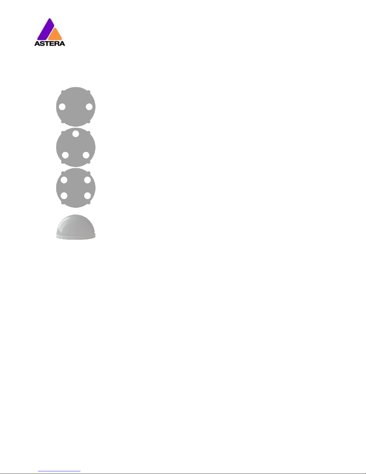
3.6 DIFFUSORS
The diffusors can be seen below:
Flood Diffusor
This diffusor sheet will produce a beam angle of 30°.
Wide-Angle Diffusor
This diffusor sheet will produce a beam angle of 120°.
Wallwash Diffusor
This diffusor sheet will produce a beam angle of 17° x 46°. This diffusor is best
suited for up lighting large flat surfaces (walls etc.).
Diffusor Dome
This diffusor dome is suited for use when the Lightdrop is inside translucent
objects. It disperses the light more evenly, leaving no hot spots.
In order to attach the diffusor, align the four wings with the four cutouts on the Lightdrop, push
into place and slide to secure. In order to remove the diffusor, do the opposite, and pull out
using the finger holes provided.
Page 8

Astera LED Technology GmbH
User Manual for AX3 Lightdrop™ 2015-05-07
Page | 7
4 SPECIFICATION
LED power:
15W
Illuminants:
1 x 15W RGBW Cree LED
Luminous Flux*:
390lm
Emittance*:
1200lx (at 2m; White 4000K)
Beam Angle:
13°
Input Voltage:
90-264V 47-63Hz / 5V 2.5A
Battery Runtime:
up to 20hrs (seamless runtime)
Wireless Module:
EU: 868.0-869.7 MHz
US: 902-928 MHz
2.4 GHz
Operating Temperature:
0°C – 40°C
32°F – 104°F
Relative Humidity:
0%-100%
Size:
120mm x 59mm x 114mm, Diameter 96.4mm
4.7“ x 2.3“ x 5.1“, Diameter 3.8“
Weight:
0.68 kg
1.4lbs
IP Rating:
IP65 (while rubber plug is in place)
* Typical Values
5 TROUBLESHOOTING
The fixture does not turn on.
The battery may be empty. Connect it to the AC and try again.
The fixture turns on and the display is on, but goes dark after showing the batter status shortly.
The fixture could be set to STANDBY mode, set to display black color or is operating in DMX
mode and doesn’t receive a valid signal. It is good practice to reset the fixture (Chapter 6.6)
between setups.
The fixture is not working correctly - it does not display the color or effect chosen.
The fixture may still be operating under a previous setting. It is good practice to reset the fixture (Chapter 6.6) between setups.
After completing a reset, the fixture still cannot be controlled by the AsteraApp™.
Make sure the RADIO PIN (Chapter 7.1) of the fixture and AsteraApp™ is the same and that it
is paired with the AsteraApp™.
The fixture does not run long enough on battery.
The required runtime can be set. It defaults to 5h. To achieve a greater battery runtime, set
the runtime to the required value. Alternatively, program the fixture to only display colors that
use less power, such as Red, Green and Blue.
If the runtime is still too short, consider that it is reduced slightly if the battery is very cold.
The charger is connected but the fixture is not charging.
The battery may be fully charged. Refer to chapter 3.3.1 for more details. The fixture will only
commence charging when its battery has a temperature of 45°C or less. Turn the fixture off
and let it cool down; once cold enough, it will start charging.
Page 9
Astera LED Technology GmbH
User Manual for AX3 Lightdrop™ 2015-05-07
Page | 8
6 OPERATION
6.1 ASTERARGB COLOR SPACE
The lights work with a specially optimized RGB color space, the AsteraRGB color space. It is
designed to eliminate the need to control each color individually to display a certain color.
Instead, the light calculates the optimum combination of all colors based on an RGB value. It
considers each LED chip’s temperature as well as an optimal color rendering.
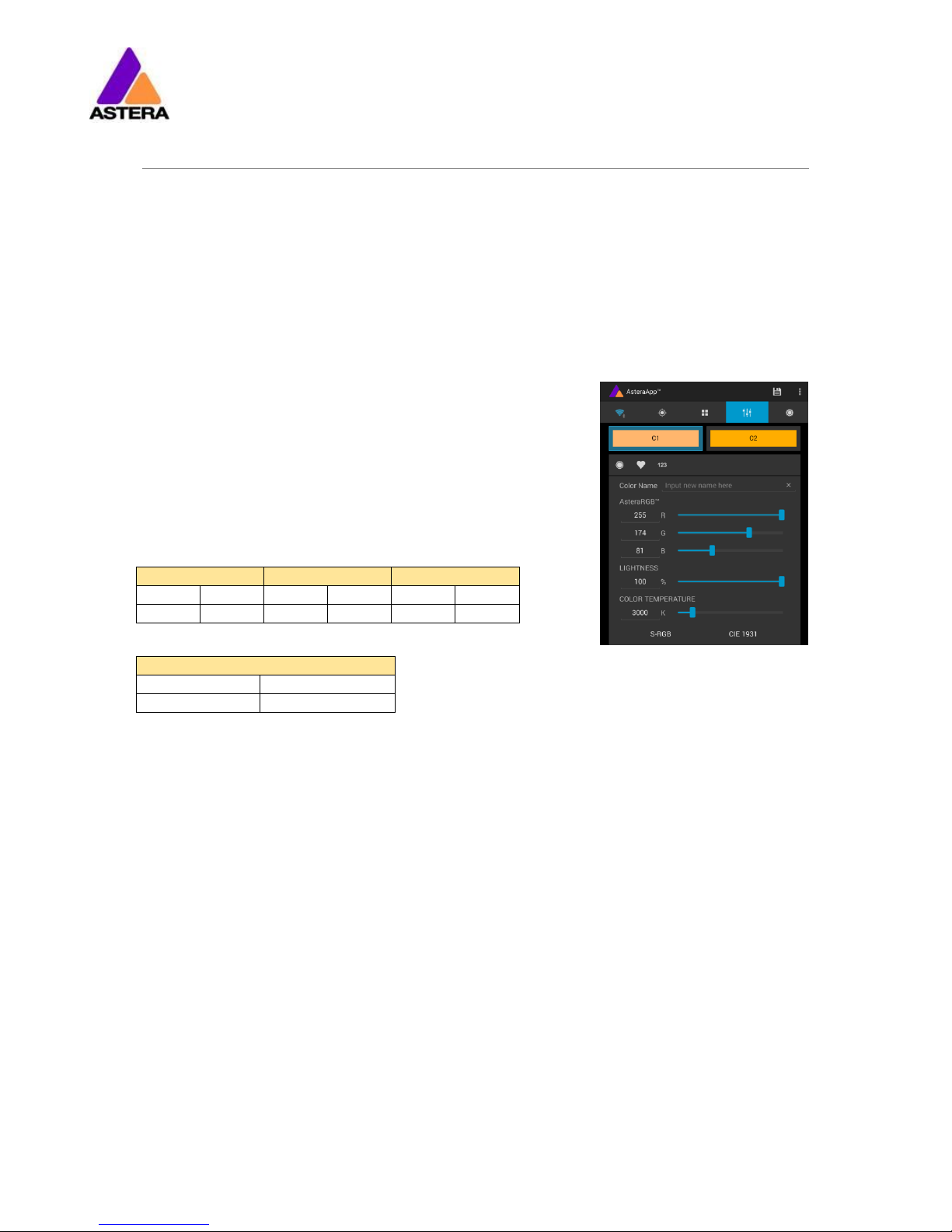
Due to this, it is possible to reproduce colors with high accuracy. It’s even possible to calculate an AsteraRGB representation for any CIE color. The easiest way to do this is with the
AsteraApp™:
Go to the color picker and add a new favorite color
Go to favorite colors and edit it
The dialog on the right will open.
It allows you to find AsteraRGB values for a certain color temperature. S-RGB or CIE1931 values can be calculated to
AsteraRGB by pressing the corresponding buttons.
The primaries of the AsteraRGB are defined as:
White Point
x
y
0.4917
0.4878
The light also includes the Dynamic Power Boost feature. It ensures that colors that consume
less electrical power are boosted slightly, while power power-consuming colors are slightly
compressed.
This maximizes the brightness while maintaining the desired battery runtime.
While controlling with the AsteraApp™, only RGB values can be set.
By DMX control, it is possible to control all colors separately. But it should be noted, that then
temperature compensation is only available for Red, Green and Blue; White will experience
temperature drift, its brightness will not be constant.
Red
Green
Blue
xR
yR
xG
yG
xB
yB
0.7079
0.2920
0.1750
0.7200
0.1566
0.0177
Page 10
Astera LED Technology GmbH
User Manual for AX3 Lightdrop™ 2015-05-07
Page | 9
6.2 WAYS TO CONTROL
The light can be controlled in several ways:
Use Astera’s ARC1 infrared remote control, point it at individual lights and
press the desired effect.
The AsteraApp™ is an efficient way to quickly create a customized light
show. It can group several lights together, address individual lights or groups
of lights, and send complex effects with a user defined color palette to all
lights in range. For additional information refer to chapter 7.
Alternatively, the Astera ARC2 remote control can be used.
The light can also be controlled by CRMX wireless DMX, the built in receiver is
compatible with all LumenRadio CRMX transmitters as well as W-DMX™ G2,
G3, G4 and G4S transmitters (G4 and G4S in 2.4 GHz mode only).
You can also use an Astera ART3 Wireless DMX Transmitter to send DMX in the
UHF frequency band, although CRMX is the recommended method.
Power the light on/off, set a static color or change its settings. (see chapter
6.8 for details on how to set a static color with the button)
CRMX is a trademark of LumenRadio AB
W-DMX is a trademark of Wireless Solution Sweden AB
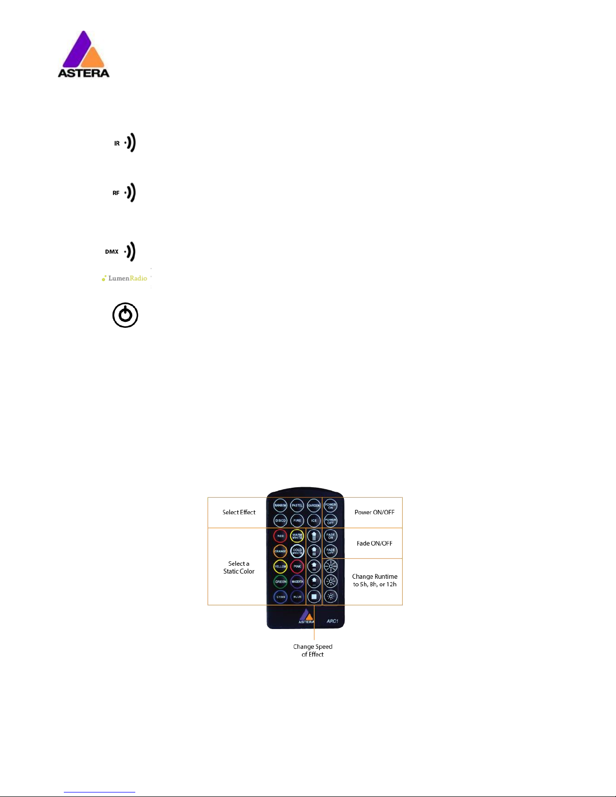
6.3 CONTROL BY INFRARED WITH ARC1
The light can be controlled by the infrared remote control if:
INPUT SELECT is set to AUTO or REMOTE CONTROL (refer to chapter 0).
The light is currently NOT operated by DMX. If it is, only ON and OFF will work while IN-
PUT SELECT is set to AUTO.
The ARC1 is very handy to switch several lights on or off at a time.
Page 11

Astera LED Technology GmbH
User Manual for AX3 Lightdrop™ 2015-05-07
Page | 10
6.4 CONTROL BY THE ASTERAAPP™
Your light has a built in standalone engine. It can display static colors or replay a number of
predefined effect patterns with a customizable color palette.
With the AsteraApp™ these effects can be created and be sent to the light by the built in
UHF receiver. The effects are just triggered and then each light replays it autonomously until it
receives a new effect.
Lights can be grouped into sets. This way they can be controlled separately and also effects
can stretch over up to 32 lights.
Also, you can remotely adjust your lights settings, this eases DMX setup for example.
For more details refer to chapter 7.
6.5 CONTROL BY WIRELESS DMX
To pair your light to a CRMX or W-DMX™ transmitter, make sure that:
Your light is not currently paired to a transmitter. To unpair do a Reset Settings (chapter
6.6).
INPUT SELECT is either set to AUTO and the light is still in detect mode –or- INPUT SELECT
is set to CRMX wireless DMX; for details refer to chapter 0.
Then press the button on your transmitter. After 10 seconds the light should be paired and
show the appropriate status screen (chapter 0).
If you prefer to use an Astera ART3 wireless transmitter, set INPUT SELECT to Astera wireless DMX
and refer to the ART3’s user manual for details.
Page 12

Astera LED Technology GmbH
User Manual for AX3 Lightdrop™ 2015-05-07
Page | 11
6.6 BUTTON
The light has two buttons. They are wired in parallel, so either of them can be used at the
user’s preference.
Press Button
Function
Press the button shortly show the status display.
Hold the button until the light turns on or off
Blue Mode: hold the button, the light will first turn off, then
back on again and it blinks blue. Chapter 6.8 explains the
Blue Mode.
Reset Settings: hold the button, the light will first turn off,
then back on again and it blinks blue. Keep holding the
button until blinking stops the light comes on red again.
NOTE:
Reset Settings also removes any CRMX / W-DMX pairing of the light.
6.7 STATUS DISPLAY
The lights main LED is double-used to display the battery status.
6.7.1 While Powered OFF
If the light is connected to the charger, the main LED either shows the battery status or is dark
to indicate that charging has finished and the battery is full.
6.7.2 While Powered ON
Press the button and the main LED will show the battery- or charging-status for two seconds.
1
2
Page 13

Astera LED Technology GmbH
User Manual for AX3 Lightdrop™ 2015-05-07
Page | 12
6.7.3 Battery Status
Battery Status
Charging
Page 14

Astera LED Technology GmbH
User Manual for AX3 Lightdrop™ 2015-05-07
Page | 13
6.8 BLUE MODE / SHOW STATIC COLOR
In blue mode, the light shows a rapid blue blinking.
This mode is used to:
Pair the light with an AsteraApp™
Switch it to display a static color without the use of any remote control
To pair the light, make sure it is in blue mode (see chapter 6.6), then press the “Pair with
Lights” button in the AsteraApp™. More details on pairing can be found in chapter 7.1.
To set a static color, while in blue mode:
Press Button
Function
Press the button shortly to cycle between the predefined
colors. All previous STANDALONE settings are cleared to
default and the INPUT SELECT is latched to STANDALONE.
This is valid until the next power-up only. To make sure the
light also shows a static color after the next power up, set
INPUT SELECT to STANDALONE and not AUTO.
To exit Blue Mode and latch the chosen color, hold the
button until the blinking stops.
6.8.1 Predefined Colors
Color
Red
Green
Blue
RED
255 0 0
ORANGE
255
107
0
YELLOW
255
160
18
GREEN 0 255
0
CYAN 0 255
224
BLUE 0 0
255
VIOLET
127
84
255
PINK
255
53
119
2700K
255
166
70
3200K
255
178
89
4000K
255
193
115
5500K
255
211
150
6500K
255
219
167
6.9 TAP THE LIGHT (FOR ASTERAAPP™)
During certain tasks, like setting up the DMX or creating a set, the AsteraApp™ asks to tap a
light.
In that case, the light will flash white shortly every two seconds.
Press Button
Function
Press the button shortly to “tap the light”. The light will
confirm with three bright white flashes.
The new configuration, like DMX address, set association
ect. is latched.
Page 15
Astera LED Technology GmbH
User Manual for AX3 Lightdrop™ 2015-05-07
Page | 14
7 USING THE LIGHT WITH THE ASTERAAPP™
The button only allows a basic operation of the light. To gain full control over all features, the
AsteraApp™ should be used.
The AsteraApp™ is an efficient way to quickly create a customized light show. It can group
several lights together, address individual lights or groups of lights, and send complex effects
with a user defined color palette to all lights in range.
Additionally, it can be used to adjust the lights settings remotely.
The AsteraBox™ is needed to interface your Android device with the lights. It communicates
to the Android device by Bluetooth and controls the lights by UHF.
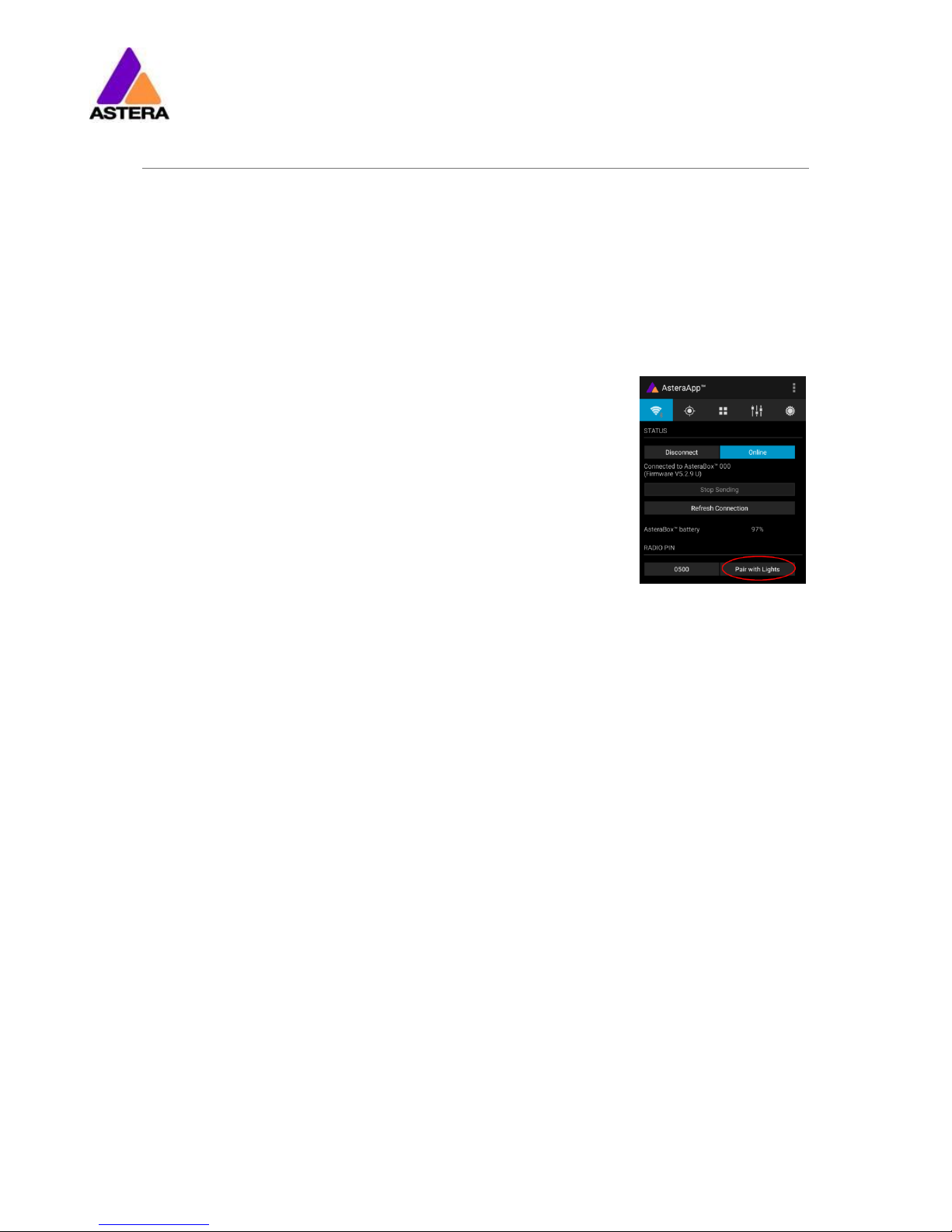
7.1 PAIR YOUR LIGHT WITH THE ASTERAAPP™
The connection is secured by a 4 digit radio pin. Only if the lights pin
matches the AsteraApp™ pin, lights are controllable.
The pairing process transmits the radio pin from the app to the light
and stores it there.
1. Choose a unique Radio Pin in the app.
2. Switch the light into blue mode, see chapter 6.6.
3. Press the “Pair with Lights” button in the AsteraApp™.
Page 16

Astera LED Technology GmbH
User Manual for AX3 Lightdrop™ 2015-05-07
Page | 15
7.2 POWERFUL LIGHT CONTROL
Your light has a built in standalone engine. It can display static colors or replay a number of
predefined effect patterns with a customizable color palette.
With the AsteraApp™ these effects can be created and be sent to the light by the built in
UHF receiver. The effects are just triggered and then each light replays them autonomously
until a new effect is sent.
Lights can be grouped into sets. This way they can be controlled separately and also effects
can stretch over up to 32 lights.
7.3 CHANGE THE COLOR
On the AsteraApps main
screen, press “Just Red”.
Once in the editor, press
“C1”.
Now the lights color can be
changed.
The “123” button offers
common color gels. Hit the
sort button to sort by color or
number (1).
To add a color to the favorites, press (2).
To edit an existing favorite
color, select it and press the
pen (1).
The editor will open. RGB
values can be adjusted directly. Also a color temperature can be converted to
RGB.
Page 17

Astera LED Technology GmbH
User Manual for AX3 Lightdrop™ 2015-05-07
Page | 16
7.4 CREATE A SET
Before the more powerful effects can be reviewed, it is recommended to create a Flow-Set
first.
Each light can be assigned to one set. Two types of sets are available:
7.4.1 SYNC SET
All lights that are assigned to a Sync-Set can be controlled together. They
will do exactly the same.
CREATE A SYNC-SET:
On the AsteraApp™ main
screen, first press the Targets
button (1) and then the “+”
sign (2) to add a new target.
Choose “Sync-Set”.
Now all lights will flicker every two seconds. Tap your
light to add it to the set
(chapter 6.9).
Additionally, the name of
the set can be customized.
When finished, press the
save button.
Page 18

Astera LED Technology GmbH
User Manual for AX3 Lightdrop™ 2015-05-07
Page | 17
7.4.2 FLOW SET
By using a Flow-Set, lights can also be controlled together. But additionally,
they are assigned to positions inside the Flow-Set and so form a virtual light
with several pixels. All effects, like a running light, are stretched over this virtual light.
CREAT A FLOW-SET:
On the AsteraApp™ main
screen, first press the Targets
button (1) and then the “+”
sign (2) to add a new target.
Then choose “Flow-Set”.
Each flow set can have up
to 32 positions. Once the
correct number is entered,
press “Confirm”.
Now your lights will flicker
every two seconds. To add a
light to the currently shown
positon of this set, press its
button. Walk through the
positions by “Previous” and
“Next” and assign your lights.
When finished, press the
save button on top.
7.5 TARGETING LIGHTS
Once you have created a set, you may now choose to control it. By
default “All lights” are targeted. That includes all sets.
It is possible to target more than one set at a time.
NOTE:
Even while targeting „All Lights” the Flow-Sets position arrangements
persist. The lights still form a virtual big light of several positions.
To modify, delete or arrange targets, use the pen button (1).
Page 19

Astera LED Technology GmbH
User Manual for AX3 Lightdrop™ 2015-05-07
Page | 18
7.6 CHANGING THE EFFECT
On the AsteraApp™ main
screen, press “Wedding” (1),
then enter the editor (2).
Set “Crossfade” to 0% and
“Speed” to around 2 sec-
onds. You should see a
clean running light now. The
White light will run over a
pink background.
The effect can be changed
by sliding the effect picker
and choosing a sub-effect
below it. Again the colors
can be adjusted, too.
After the effect is adjusted, it may be saved back to the main screen by pressing the save
button.
AN EFFECT CAN BE HIGHLY CUSTOMIZED:
The speed tells how long it will take for the effect to complete one cycle.
The crossfade tells if the light will fade from step to step. If it is set to 0% an immediate change
is visible. If set to 100% the changes will be soft.
Stroboscope effect can be enabled and seamlessly adjusted in speed. Additionally, three
random stroboscope options are available: slow, medium and fast.
Each effect can be adjusted in brightness as well.
Page 20

Astera LED Technology GmbH
User Manual for AX3 Lightdrop™ 2015-05-07
Page | 19
7.7 LIST OF EFFECTS
The effects patterns are pre-defined and cannot be modified by the user. They are preprogrammed inside of each light. Still they can be parameterized. These are available:
A static color is displayed. There are also options that show two, three or four
static colors at a time. The Flow-Set is then divided into several parts of equal
length.
Fading colors. The four defined colors are displayed one after the other. The
setup fade is applied between them. Again, the Flow-Set can be split in up
to four segments.
From both sides of a Flow-Set, the color changes position by position from C1
to C2. Once the whole Set is C2, it changes back to C1 in the same way.
The color of the Flow-Set changes position by position. After all positions
show the same color, a new cycle is started.
Several variations of running lights are available.
The Fire effect shows a random flickering effect. The background color and
the color of the flickering effect can be adjusted.
The rainbow effect shows a color change through all colors. Only its speed
can be adjusted.
Chaser effects provide an efficient means to create dancefloor lighting. The
static chaser exchanges the color of the lights according to the tapped-in
beat. The colors are randomly chosen. The effect can be adjusted to show
up to 4 different colors at a time.
The Moving Chasers overlay the static chaser by a second movement of the
four displayed colors over the available positions of a Flow-Set. This gets
mostly interesting of the Moving Strobe is chosen. Then, only some of the
positions strobe and they are moving. So the strobe effect moves over the
Flow-Set.
When using the Chaser With Background, additionally a color can be selected that is mostly used, the background color.
Page 21

Astera LED Technology GmbH
User Manual for AX3 Lightdrop™ 2015-05-07
Page | 20
7.8 CHASER EFFECTS IN DEEP
To display chaser effects it is recommended to setup a Flow-Set with a multiple of four positions. This way they will be shown best. Those four positions could then be arranged in the
corners of a dance floor for example.
Use the tap-sync button to tap the beat of the music; the Chaser Effects will base their color
changing on that beat then.
The Chaser Effects offer additional controls
The Emphasis adjusts the way the colors are exchanged by the chaser:
Emphasis
Effect
-2
The four colors of the palette are exchanged one by one. Every beat changes
only one color.
-1
Same as “-2”, but the color change is animated with the color-wheel effect; it
mimics the color change of a traditional color wheel, showing intermediate
colors during the change.
0
All four colors are exchanged on every beat.
1
Same as “0”, but the color wheel effect is added.
2
Same as “0”, but on the fourth beat, all colors go black. They come on again
on the next beat.
3
Same as “0”, but all colors go black on every second beat. This setting produces a strong on-off effect in sync with the beat.
The softness influences the fading between colors that happens on every beat. 0% will generate a hard change of the colors, while 100% makes them fade very slowly.
A random button is added to the color bar. If it is latched, random colors are chosen on every beat. If not (like in the above picture), then the colors are always chosen randomly from
the color pallet of four. This is useful to intentionally narrow down the color choice. Nice effect
can be generated by setting some of them to black.
Page 22

Astera LED Technology GmbH
User Manual for AX3 Lightdrop™ 2015-05-07
Page | 21
7.9 THE MAIN SCREEN
Here each program is represented by a tile. Those tiles can be edited and freely positioned.
Several pages of tiles are available.
To move or delete a tile,
press the pen icon (2). A
popup will show the available actions.
To add a new program tile,
press the “+” icon (1).
While adding a tile, either a
default “Static Red” or the
currently running program
can be selected.
Additionally, special function
tiles are available.
7.9.1 Function Tiles
Tapping this tile several times to the beat will let the Chaser Effects change their colors to the beat. A chaser effect has a
dancer symbol on the tile.
This button can be used to quickly blackout lights. The currently set target
must be observed, as the blackout function will only affect the currently targeted lights.
Page 23

Astera LED Technology GmbH
User Manual for AX3 Lightdrop™ 2015-05-07
Page | 22
7.10 BRIGHTNESS
Additionally to each programs brightness slider mentioned in chapter 7.6, a master brightness
control is available.
As soon as more than one Set is created
and at least one set is currently targeted, a sub-master for each Set is shown.
Otherwise, only one slider is available. It
controls the brightness of all currently
targeted lights.
7.10.1 Set Sub-Masters
Each Set has its own brightness slider. Additionally, there is a master slider that controls the
brightness of all Sets simultaneously. This is very similar to the group brightness control of common lighting desks.
NOTE:
The Set-Masters are only shown if:
a) More than one Set has been created before
b) Only Set-Targets are currently selected. Selecting any other type of target, like “All
Lights” will hide the Set-Masters. This is necessary to avoid that one lights gets redundant brightness information; it would flicker constantly between different brightness
levels.
7.11 RUNTIME
The light is able to adjust its power to meet a certain runtime on battery. The
runtime is always calculated for a full battery.
Example:
If the light is required to light during an eight hour event, and one
hour of setup time is scheduled, then the runtime should be set to
nine hours immediately after the first power up.
Please note, that the light should not be stored below 20°C before an event,
otherwise the runtime might be shorter than calculated.
More details on the built in battery can be found at chapter 0.
Page 24

Astera LED Technology GmbH
User Manual for AX3 Lightdrop™ 2015-05-07
Page | 23
7.12 THEFT ALARM
Your light is equipped with a theft alarm. A motion sensor in the light detects when it is
moved/taken away and a small siren will sound to deter potential thieves.
First make sure your Radio
Pin is different from 0000. See
chapter 7.1 how to change
it. Then press the “ON” but-
ton.
Press “Activate”. All targeted
lights will flash shortly to indicate that they are now
armed.
If the siren is set to DELAYED, it sounds only if the
alarm persists for more than 6 seconds. The ON setting makes it sound immediately, while the OFF setting mutes it always.
The sensitivity can be adjusted to meet your environment. A lower value makes a false alarm more
unlikely.
In case a potential thief is taking the light away while
ignoring the alarm, he will most likely cause alarm
events for more than 2 minutes in a row. In that case,
the alarm can be set to become permanent. Then it
won’t stop, even if the light is placed down again. It
will run until the battery is empty, rendering the light
useless for the thief.
In some applications it is not desirable to have the
lights flashing while the alarm is enabled or disabled.
It can be disabled by this option easily.
The alarm can be silenced without turning it off by
pressing this button.
NOTE:
To turn the alarm off again, an AsteraApp™ with the same Radio Pin must be used. Do not
forget your Radio Pin! Otherwise, your light cannot be used normally anymore.
Page 25

Astera LED Technology GmbH
User Manual for AX3 Lightdrop™ 2015-05-07
Page | 24
7.13 ANTI-FLICKER
The PWM refresh rate of this light is 599.4 Hz by default. This frequency can be freely adjusted
between 200 Hz and 1205 Hz to fit different camera’s frame rates.
Make sure you have targeted the lights you wish to adjust (chapter 7.5).
Then press the “Anti-Flicker”.
Slide the “fps” to adjust to
default values for a framerate.
Slide the “Hz” to fine-adjust.
Press the highlighted frequency to enter a custom
value between 200 and
1205 Hz.
NOTE:
The Anti-Flicker adjustment is preserved in case the lamp is powered off.
It is set back to the default 599.4Hz once a Reset Settings (chapter 6.6) is done.
The adjusted frequency is used no matter what input source is currently active. Also during
DMX operation.
Page 26

Astera LED Technology GmbH
User Manual for AX3 Lightdrop™ 2015-05-07
Page | 25
7.14 ENTER AND LEAVE STANDBY
The standby is intended to be used between setup and event (see chapter 3.3.1). After setup
is completed, all lights may be switched to standby mode and woken up later when the
event starts. This ensures that no battery runtime is wasted. This can be either done manually
or automated.
Press the small arrow to
open the standby menu.
By pressing the “Now” but-
tons, standby can be
switched on or off for all currently targeted lights.
Any of the “Later” buttons
will require a time to be set.
The standby will be scheduled to the specified time.
NOTE:
While you are using the “Now” function, only those lights that are currently targeted are addressed (see chapter 7.5 how to target lights).
The “Later” function always sends to the “All Lights” target!
NOTE:
To check if the light is completely powered off or only in standby mode, press the power button shortly. If it stays dark it is powered off.
Page 27

Astera LED Technology GmbH
User Manual for AX3 Lightdrop™ 2015-05-07
Page | 26
7.15 DMX SETTINGS
To efficiently use the light with DMX, some settings can be adjusted by the AsteraApp™.
Press the “DMX Configuration” button.
Adjust all settings to your
requirements, then press
“Send”.
Your lights will start to flicker.
Tap the lights you wish to
setup (chapter 6.9). Then
press “Done”.
7.15.1 DMX Address
The address can be either entered directly, or adjusted by the “+” and “-“ buttons.
7.15.2 DMX Failure
It can be set what the lights should do when the DMX signal is lost.
The last DMX input is still shown,
even if the DMX signal is lost.
The light will show a 4000K white
as soon as the DMX signal is lost.
The light will go dark if DMX signal is lost.
The light will switch temporarily
to standalone mode if the DMX
signal is lost and show for example a preset static color.
Auto
Hold
Emergency Light
Blackout
Standalone
Page 28

Astera LED Technology GmbH
User Manual for AX3 Lightdrop™ 2015-05-07
Page | 27
7.15.3 Input Select
The light accepts several input sources. By default, it is set to AUTO. In this mode, it listens to all
sources, and the first source that becomes active is latched. Once a source is latched, the
light will not listen to any other source anymore.
This latched source is cleared by powering down the light or changing the INPUT SELECT
manually.
Auto mode; the lights waits for
any input signal and latches the
first detected source.
In standalone mode, neither
wireless DMX nor remote control
is accepted.
The light can be control by the
AsteraApp™, but any DMX signal is ignored.
Only Astera wireless DMX is accepted, all other sources are
ignored.
Only CRMX/W-DMX wireless
DMX is accepted, all other
sources are ignored.
The following table shows what sources are accepted for each setting:
Source INPUT SELECT
AUTO, none latched AUTO,
STANDALONE latched
AUTO, REMOTE CONTROL
latched AUTO, Astera wirel. DMX latched AUTO, CRMX wirel. DMX latched STANDALONE REMOTE CONTROL Astera wirel. DMX CRMX wirel. DMX
AsteraApp™: change colors
● ● ●
AsteraApp™: STANDBY, RUNTIME, ALARM
● ● ● ● ● ●
AsteraApp™: DMX Settings
● ● ● ● ● ● ● ●
Astera Wireless DMX
● ● ●
CRMX Wireless DMX
● ● ●
Infrared Remote
● ● ● ● ● ●
The Light’s Control Panel
● ● ● ● ● ● ● ● ●
HINT:
To avoid the light automatically latching onto CRMX while you want to control it by remote
control, please unpair it first (chapter 6.6). As soon as the remote control is latched, the CRMX
receiver will no longer accept pairing requests.
Input Select
Auto
Standalone
Remote Control
Astera Wireless DMX
CRMX Wireless DMX
Page 29

Astera LED Technology GmbH
User Manual for AX3 Lightdrop™ 2015-05-07
Page | 28
7.15.4 Strobe and Table
A number of DMX tables are available, see chapter 7.15.5 for details.
For each of the tables, the strobe channel can be enabled or disabled.
7.15.5 DMX Tables
Each of the tables can optionally contain a strobe channel. It can be switched on or off. The
tables below list it, but in case it is set to None, the DMX-channels are unused.
7.15.5.1 RGB S
CHANNEL
VALUE
FUNCTION
1
0..255
RED
2
0..255
GREEN 3 0..255
BLUE
4 STROBE (only if STROBE is ON)
0..3
OFF 4
RANDOM FAST
5 RANDOM MEDIUM
6 RANDOM SLOW
7..255
Variable strobe
7.15.5.2 RGBW S
CHANNEL
VALUE
FUNCTION
1
0..255
RED 2 0..255
GREEN 3 0..255
BLUE 4 0..255
WHITE
5 STROBE (only if STROBE is ON)
0..3
OFF 4
RANDOM FAST
5 RANDOM MEDIUM
6 RANDOM SLOW
7..255
Variable strobe
7.15.5.3 RGBAW S
CHANNEL
VALUE
FUNCTION
1
0..255
RED 2 0..255
GREEN 3 0..255
BLUE 4 0..255
FREE (this light does not have AMBER LEDs)
5
0..255
WHITE 6
STROBE (only if STROBE is ON)
0..3
OFF
4 RANDOM FAST
5 RANDOM MEDIUM
6 RANDOM SLOW
7..255
Variable strobe
Page 30

Astera LED Technology GmbH
User Manual for AX3 Lightdrop™ 2015-05-07
Page | 29
7.15.5.4 RGB CCT DIM IND S
CHANNEL
VALUE
FUNCTION
1
0..255
RED 2 0..255
GREEN
3
0..255
BLUE
4 COLOR TEMPERATURE (CCT)
0..4
no effect 4..255
display color temperature; CCT overwrites the RGB setting
Formular: CCT = 2000 + 20*DMX-Value
Example: 50 -> 3000K
100 -> 4000K
150 -> 5000K
5
0..255
Dimmer
6 INDEX COLOR
0..4
no effect
4..255
display index color (common gels); INDEX COLOR overwrites both, RGB
and CCT. 7
STROBE (only if STROBE is ON)
0..3
OFF
4 RANDOM FAST
5 RANDOM MEDIUM
6 RANDOM SLOW
7..255
Variable strobe
7.15.5.5 DIM RGB S
CHANNEL
VALUE
FUNCTION
1
0..255
Dimmer 2 0..255
RED 3 0..255
GREEN 4 0..255
BLUE 5
STROBE (only if STROBE is ON)
0..3
OFF 4
RANDOM FAST
5 RANDOM MEDIUM
6 RANDOM SLOW
7..255
Variable strobe
7.15.5.6 DIM RGBW S
CHANNEL
VALUE
FUNCTION
1
0..255
Dimmer 2 0..255
RED
3
0..255
GREEN
4
0..255
BLUE 5 0..255
WHITE 6
STROBE (only if STROBE is ON)
0..3
OFF 4
RANDOM FAST
5 RANDOM MEDIUM
6 RANDOM SLOW
7..255
Variable strobe
7.15.5.7 DIM RGBAW S
CHANNEL
VALUE
FUNCTION
1
0..255
Dimmer 2 0..255
RED 3 0..255
GREEN 4 0..255
BLUE
5
0..255
FREE (this light does not have AMBER LEDs)
6
0..255
WHITE
7 STROBE (only if STROBE is ON)
0..3
OFF 4
RANDOM FAST
5 RANDOM MEDIUM
6 RANDOM SLOW
7..255
Variable strobe
Page 31

Astera LED Technology GmbH
User Manual for AX3 Lightdrop™ 2015-05-07
Page | 30
7.15.5.8 Effect Modes
There are two effect modes available. They offer a comprehensive control of the built in
standalone engine. Settings that can otherwise only be changed on the LCD menu or by the
AsteraApp™ can be directly adjusted by DMX. The two effect modes only differ in the way
the color palette of four colors is set: either by RGB or by a single channel, like a color wheel.
In that case, common gels can be selected directly. Strobe is always enabled for the effect
modes.
CHANNEL
VALUE
FUNCTION
EFFECT
MODE FIX
EFFECT
MODE RGB 1 1
0..255
INTENSITY 2 2 STROBE
0..3
OFF 4 RANDOM FAST
5
RANDOM MEDIUM
6
RANDOM SLOW
7..255
Variable strobe
3 3
PROGRAM:
0..7
ONE COLOR STATIC
8..15
TWO COLOR STATIC
16..23
THREE COLOR STATIC
24..31
FOUR COLOR STATIC
32..39
ONE COLOR FADE
40..47
TWO COLOR FADE
48..55
THREE COLOR FADE
56..63
FOUR COLOR FADE
64..71
SIMPLE RUNNING
72..79
DOUBLE RUNNING
80..87
TWO COL RUNNING
88..95
FLAG RUNNING
96..101
DOUBLE FLAG RUNNING
102..109
SPIRAL 4 COLOR
110..117
SPIRAL 2 COLOR
118..125
RAINBOW
126..133
FIRE
134..141
ROTOR
142..149
ROTOR SPLIT 2
150..157
ROTOR SPLIT 4
4 4 0..255
SPEED 5 5
0..255
FADE 6 6 DIRECTION:
0..63
FFW+LOOP
64..127
FFW
128..190
REW
191..255
REW+LOOP 7 7 SIZE:
Defines the virtual size of the program in groups. For example if SIZE is set to 2 groups, only half of the program is shown on
the unit.
0..63
1 Group
64..127
2 Groups
128..190
3 Groups
191..255
4 Groups 8 8 OFFSET:
0..255
If SIZE is set to >1 group, the units pixels can be shifted within the virtually larger
program. Increasing the OFFSET parameter scrolls the position of the unit within the virtual large program.
9 9 0..255
RESTART PROGRAM
if value is changed, the program starts again from the beginning (useful if
DIRECTION is not set to loop)
10
INDEX COLOR 1
11
INDEX COLOR 2
12
INDEX COLOR 3
13
INDEX COLOR 4
10 RED 1 11 GREEN 1 12 BLUE 1 13 RED 2 14 GREEN 2 15 BLUE 2
16 RED 3
17 GREEN 3 18 BLUE 3 19 RED 4
20 GREEN 4 21 BLUE 4
Page 32

Astera LED Technology GmbH
User Manual for AX3 Lightdrop™ 2015-05-07
Page | 31
7.15.6 DMX Channel Assignment
The current channel assignment can be always reviewed in the lower part of the screen. It is
automatically calculated based on the setting of Table and Strobe.
 Loading...