

Page 1

ASTECH ELECTRONICS LIMITED
OPERATI
NG INSTRUCTIONS
SINGLE CHANNEL ‘D’ RANGE
ROTARY/SHORT RANGE TELEMETRY EQUIPMENT
©
Ast
ech Electronics Ltd
Reproduction of any written material or illustration in this publication
in
any form or for any purpose is expressly forbidden
unless the prior consent of Astech Electronics Limited has been given in writing
Forge Industrial Estate, BINSTED, Alton, Hampshire GU34 4PF, England.
Tel: 01420 22689, Fax: 01420 22636
Via Paolo Uccello 4 - 20148 Milano
Tel +39 02 48 009 757 Fax +39 02 48 002 070
[email protected] www.dspmindustria.it
Page 2

TM Page 2
Page 3

TM Page 3
CONTENTS
1 ASTECH ROTARY TELEMETRY SYSTEMS - GENERAL DESCRIPTION 5
2 LIST OF SYSTEM ITEMS & SERIAL NUMBERS 6
3 Transmitters 7
3.1 Transmitter TX31D/1/IFM 7
3.1.1 TX31D/1/IFM Input Connections & Scaling 8
3.1.2 TX31D/1/IFM Calculation of Shunt Calibration Resistor "Rcal" 9
3.1.3 TX31D/1/IFM Mounting and Cover Plate 9
3.1.4 TX31D/1/IFM Specifications 1
0
3.2 Transmitter TX34/1/IFM 1
1
3.2.1 TX34D/1/IFM Input Connections & Scaling 12
3.2.2 TX34D/1/IFM Calculation of Shunt Calibration Resistor "Rcal" 12
3.2.3 TX34D/1/IFM Mounting and Cover Plate 12
3.2.4 TX34D/1/IFM Specifications 13
3.3 Transmitter TX35/1/IFM 1
4
3.3.1 TX35D/1/IFM Input Connections & Scaling 15
3.3.2 TX35D/1/IFM Calculation of Shunt Calibration Resistor "Rcal" 15
3.3.3 TX35D/1/IFM Specifications 15
4 DEMODULATOR RE3D 1
6
4.1 RE3D Front and Rear Panels 16
4.2 RE3D Controls & Connections 1
8
4.2.1 RE3D Specifications 18
4.3 RE3D Programing 20
4.3.1 Programming Notes 20
4.3.2 Setting the Display Resolution 21
4.3.3 Program Flow Charts 2
1
4.3.3.1 RE3D With TX34D Transmitter 22
4.3.3.2 RE3D With TX31D Transmitter 23
4.3.4 RE3D Programming Menu 24
4.3.5 Display Menu 24
4.3.6 Analogue Outputs Menu 2
4
4.3.7 Trim Adjust Menu 25
4.3.7.1 Strain Zero trim 25
4.3.7.2 Strain Gain trim 25
4.3.8 Strain Display Menu 25
4.3.8.1 Strain Units 25
4.3.8.2 Strain scaling 2
5
4.3.9 Strain Transmitter Setup 25
4.3.9.1 Input type 25
4.3.9.2 Transducer mV/V 26
4.3.9.3 µε Full Scale 26
4.3.9.4 Calculated Gain 2
6
4.3.9.5 Calibration Resistor 26
4.3.9.6 Gauge Setup 26
4.3.9.7 Shaft Size 26
4.3.9.8 Shaft Material 26
4.3.10 TXxx Control 2
7
4.3.10.1 TX34 Calibration Mode 2
7
4.3.10.2 TX34 Zero Adjust 27
4.3.10.3 TX34 Input Invert 27
4.3.10.4 Show TX34 Setup 27
Page 4

TM Page 4
4.3.11 Tachometer Settings Menu 2
7
4.3.11.1 Set the Number of Tachometer Flags 27
4.3.11.2 Set the Full Scale RPM 27
4.3.12 Decoder Settings Menu 28
4.3.12.1 Set the transmitter type 28
4.3.12.2 Set the Output Calibration Mode 28
4.3.12.3 Set the OLED Display Brightness 2
8
5 INDUCTIVE POWER SUPPLY & TRANSMITTER INSTALLATION 29
5.1 Inductive Head IH2 or IH2/L with shaft mounted power pickup loop 3
0
5.1.1 Inductive Head IH2 or IH2/L with Power Pickup Loop in Split-Ring Assembly "TX.MTGS" 30
5.1.2 Suggested Installation for Inductive Head IH2-IH2/L with Power Pickup Loop in Split-Ring
Assembly 31
5.1.3 Inductive Head IH2 or IH2/L with Power Pickup Loop Wound onto Shaft Using CAK Kit 32
5.1.4 Suggested Installation Sequence for Inductive Head IH2 or IH2/L with Transmitter & Power
Pickup Loop Using CAK Kit: 32
5.2 Inductive Loop IL2 with shaft mounted power pickup loop or ip2 pickup 3
3
5.2.1 Inductive Loop IL2 with Power Pickup Loop in Split Ring Assembly "TX.MTGS" 33
5.2.2 Suggested Installation Sequence for Inductive Loop IL2 with Power Pickup Loop Integrated in
Split-Ring Assembly 34
5.2.3 Inductive Loop IL2 with Power Pickup Loop Wound onto Shaft Using CAK Kit 3
5
5.2.4 Suggested Installation Sequence for Inductive Loop IL2 with Transmitter & Power Pickup Loop
on Shaft Using CAK Kit: 36
5.2.5 Inductive Loop IL2 with Inductive Power Pickup IP2 on Shaft Using CAK Kit 37
5.2.6 Suggested Installation Sequence for Inductive Loop IL2 with Transmitter & IP2 Power Pickup
on Shaft Using CAK Kit: 39
6 SYSTEM CHECKOUT 3
9
6.1 Non-Operation 40
6.2 Improving Efficiency of Inductive Power Supply 4
0
6.3 Attaching transmitter/IP2 pickup module on small diameters 41
6.4 Dimensioned drawings of IH2 & IL2 4
2
Page 5
TM Page 5
1 ASTECH ROTARY TELEMETRY SYSTEMS - GENERAL DESCRIPTION
Astech Rotary Telemetry Systems enable the measurement of physical quantities – torque, strain,
t
emperature or vibration for example, on rotating or moving components, by means of non-contacting radial
data transmission. In addition to providing a wire-free method of transferring the measurement data to a
stationary pickup, the systems incorporate signal conditioning for the component mounted transducers, and
outputs in either analogue or digital serial formats.
T
he telemetry system is based around the RE3D Demodulator. This is a highly sophisticated unit that can output digital and
analogue data collected from a variety of transmitter types. The built in microcontrollers allow onboard computation of
strain and power directly from mechanical parameters entered into the unit from the front panel or using a PC/laptop via a
USB interface. Circuitry and hardware comprising of a demodulator, pcm decoder and analogue output conditioning circuitry
– digital zero and output level trimmers, signal status indicators etc., are contained within a compact extruded aluminium
enclosure type RE. An inductive power supply oscillator, which replaces batteries as the transmitter power source, is also
incorporated. This can be disabled allowing battery powered transmitters to be used. The power supply is highly flexible
allowing the unit to be powered by either a 9-30VDC source at 1A or a 90-260VAC mains voltage.
Output conditioning circuitry provides filtering, zero adjustment and output level adjustment. Maximum output levels are ±
10V. A tachometer input allows shaft RPM to be displayed. Valid data reception is indicated by the presence of a front
panel red ‘Error’ LED. Depending on the transmitter type various signals can be output. For example, using a TX34D or
TX35D allows the display and output of strain, power, and transmitter power supply voltage and transmitter temperature.
The new programmable transmitters, eg TX34D/TX35D, allow the RE3D to be used to set the gain, offset and calibration.
This is done by sending commands via the inductive power supply to the microcontroller on the transmitter. This allows the
gain offset and calibration to be controlled whilst the transmitter is installed.
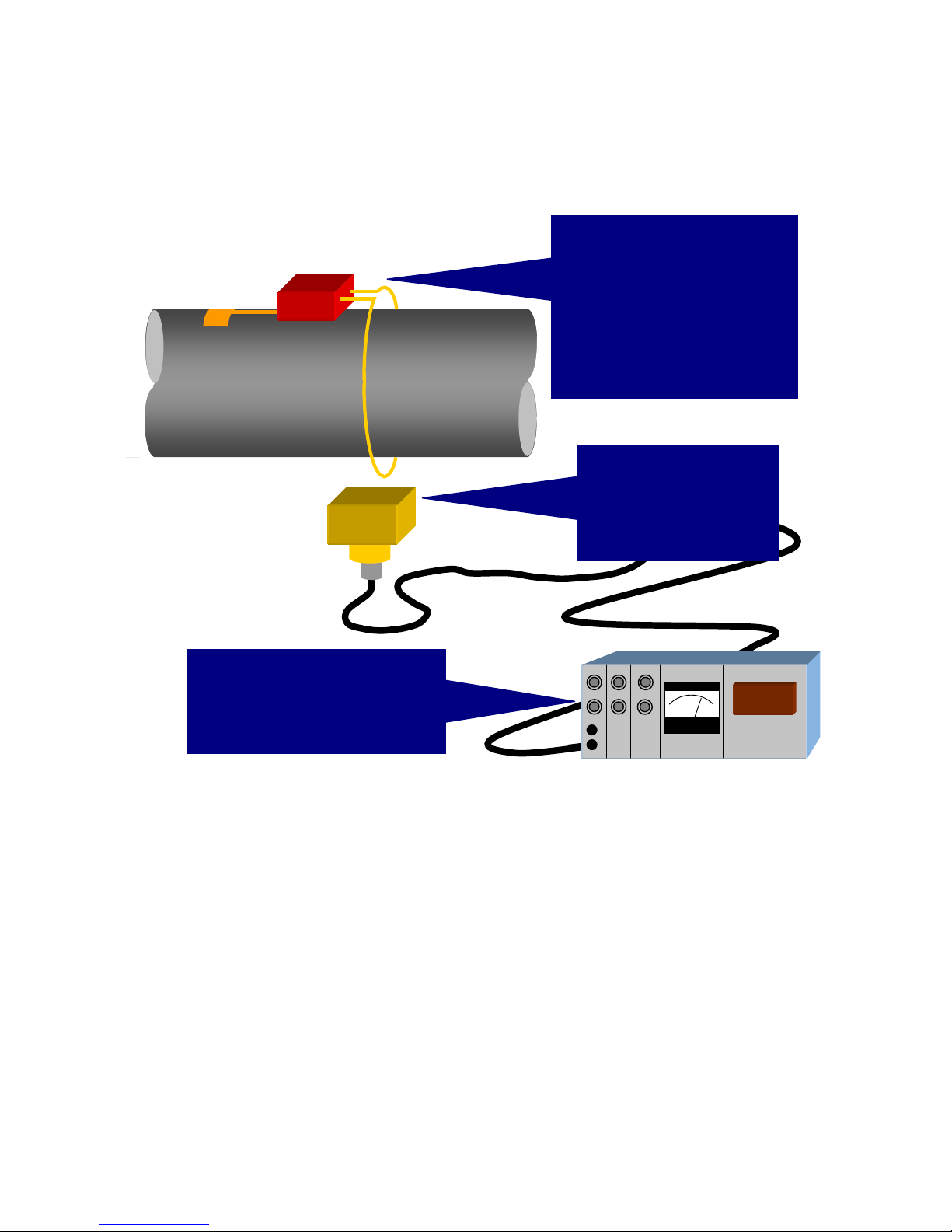
The received data is decoded into analogue
voltage outputs, or alternatively converted to
serial data for input into a PC. Various types
of demodulator/readout hardware are
available, including benchtop, industrial and
compact versions for in-vehicle use.
A miniature transmitter and power pickup
loop or battery pack are attached to the
rotating shaft or component. The
transmitter converts the transducer
outputs into a frequency modulated signal,
enabling transfer from the rotating shaft to
a stationary pickup. The standard
transmission method is by inductivecoupling, but alternatives including infrared, radio and capacitive coupling are also
available for special applications.
A pickup, combined with an
energising head in the case of
inductively powered systems,
collects the data and retransmits via cable to the system
demodulator and readout
hardware.
769
Page 6

TM Page 6
2
LIST OF SYSTEM ITEMS & SERIAL NUMBERS
(Example)
1 x Transmitter Type TX34D/1/IFM (1 Strain Input Channel and Supply V Monitor Channel) plus Screening Cover &
CAK Mounting Baseplate S/No. 3203
1 x CAK Shaft Mounting Kit
1 x Inductive Power Supply/Signal Pickup Head Interface Module IH2 S/No. 3205
1 x Mounting Bracket for Inductive Head & Loop Interface Module.
1 x 5 Metre Co-axial Connecting Cables terminated with TNC Plugs.
1 x RE3D/IFM/1 Single Channel Demodulator/Decoder plus 3 Pin Input Power Connector. S/No. 3204
1 x Operating Instructions + Drawings of TX31D, IH2 & IL2
Page 7
TM Page 7
3 TRANSMITTERS
3
.1 TRANSMITTER TX31D/1/IFM
The single channel (plus power supply monitor channel) TX31D/1/IFM transmitter is a compact, low profile design, used
when a minimum diameter for the shaft mounted hardware is required. The lightweight machined aluminium housing is
drilled to accept a screening cover and slotted base-plate fixture (for use with the shaft clamp assembly kit CAK). Power
supply is normally by inductive coupling into a single turn pickup loop, either wound around the shaft periphery (and
separated from the shaft by an insulating standoff layer), or located within a groove machined into the split-ring assembly
O.D. The transmitter may also be powered by batteries. For example, two ½ AA size lithium cells usually housed within a
TX.MTGS split ring assembly, or the TX31 battery unit.
Circuitry consists of an input filter followed by an instrumentation amplifier, stabilised bridge excitation supply of 4.096VDC,
12 bit A/D converter plus control logic, rectification circuitry to convert the incoming AC inductive power to filtered DC (not
used if battery powered) and finally, a 10.7 MHz fm output stage. The input amplifier gain controls the overall system
sensitivity and is set by an external resistor "Rg", which is user fitted between two pins on the transmitter. A remote
calibration facility is incorporated into the input stage and is activated by temporarily interrupting the transmitter power
supply (i.e. turn off demodulator module power). When power is re-applied, a shunt calibration resistor is connected across
one arm of the strain gauge input circuit for a period of 10 seconds. The shunt calibration resistor is user fitted across two
solder pins.
Signal transmission is by inductive coupling of the 10.7MHz f.m. carrier from a single-turn loop wound around the shaft (in
an inductively powered system this loop also collects power) and an inductive head IH1 (IH2 or inductive loop IL2 for
inductively powered transmitters). Transmission range is typically 50-200mm, reducing to 10-15mm for inductively powered
transmitters, this being the maximum airgap across which sufficient electrical power for the transmitter can be transferred.
In construction, the transmitter circuitry is encapsulated in epoxy resin within a machined aluminium housing with solder
pins providing the input connections to the strain gauge leadwires, inductive power/pickup loop and sensitivity setting/shunt
calibration resistors. The transmitter housing is drilled with 4 x M3 clearance holes for attachment of the screening cover
and mounting baseplate.
P4
P3
P2
P1
P6
P5
P8
P7
P1
0
P9
P11
P13
P12
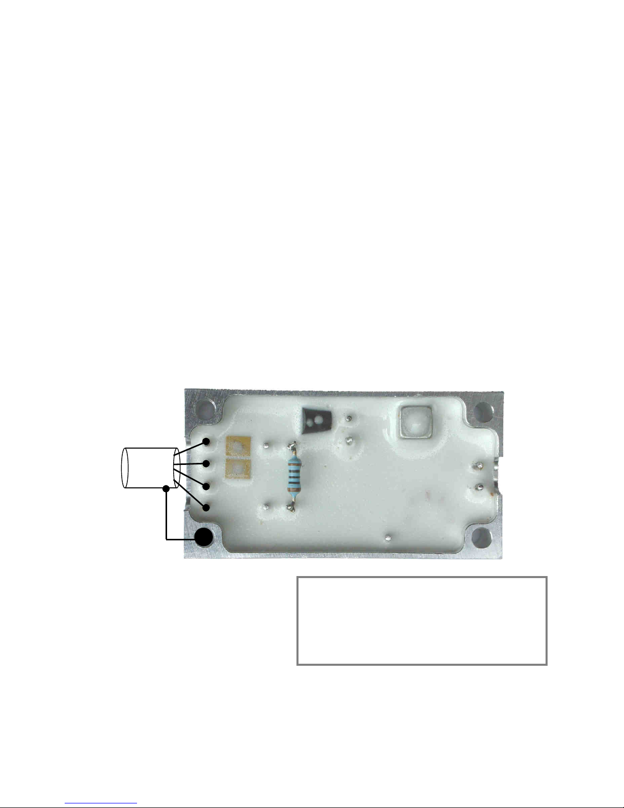
Figure 1 - TX310D/1/IFM Transmitter Connections
P1= 0V EX
P2= - SIG
P3= + SIG
P4= +4.096V EX
P5= R cal
P6= R cal
P7= R gain
P8= R gain
P9= +V IN
P10= 0V & HOUSING
P11= PCM TEST
P12= LOOP ANT
P13= LOOP ANT
IF THE TRANSMITTER IS CLOSE TO INDUCTIVE HEAD:
1) Use screened cable for gauge leads
2) Fit supplied metal cover to screen transmitter circuitry
3) Connect signal cable screen to transmitter housing
Failure to do this may result in a zero shift once per
revolution due to inductive power magnetic field pickup
Page 8

TM Page 8
3.1.1 TX31D/1/IFM Input Connections & Scaling
Input sensitivity of the transmitter input is set by a resistor (Rg), which is soldered across pins P6 and P7. This sets the
g
ain of the input amplifier such that its output at (at full scale signal input) uses ±41.5% of the total A/D convertor range.
The remaining ±8.5% allows signal source offsets of up to ±20% of full scale to be within the dynamic range of the system
and thus removable at the demodulator/decoder unit (via the zero control).
From 1/1/2006 all transmitters have VEx increased from 4.096V to 5VDC. As the A/D converter uses VEx as a reference,
the input sensitivity equation is slightly altered. Equation for both version are listed below:
Transmitters with+ 4.096VEx
Rg is calculated from:
Alternatively:
Full Scale mV In is the mV output from the strain gauge bridge, transducer or other signal source.
In the case of a four arm fully active torsion bridge, the mV output for a given strain may be calculated from:
E = Strain in Microstrains
G.F. = Gauge Factor
4.096 = Bridge Excitation Voltage
Transmitters are usually shipped with Rg=100 ohms, giving a full scale input sensitivity of;
Transmitters with+5.0VEx
Rg is calculated from:
Alternatively:
Full Scale mV In is the mV output from the strain gauge bridge, transducer or other signal source.
In the case of a four arm fully active torsion bridge, the mV output for a given strain may be calculated from:
E = Strain in Microstrains
G.F. = Gauge Factor
4.096 = Bridge Excitation Voltage
Transmitters are usually shipped with Rg=100 ohms, giving a full scale input sensitivity of;
50,000 x Required Full Scale mV In
1,700 - Required Full Scale mV In
Rg (ohms) =
1,700 x Rg
50,000 + Rg
Full Scale Range in mV =
mV =
E x G.F. x 4.096
1,000
1,700 x 100
50,000 + 100
Full Scale Range in mV =
= ±3.393mV
50,000 x Required Full Scale mV In
2,075.2 - Required Full Scale mV In
Rg (ohms) =
2,075.2 x Rg
50,000 + Rg
Full Scale Range in mV =
mV = =
E x G.F. x 5
1,000
2,075.2 x 100
50,000 + 100
Full Scale Range in mV =
= ±4.142mV
Page 9
TM Page 9
3.1.2 TX31D/1/IFM Calculation of Shunt Calibration Resistor "Rcal"
T
wo solder pins P5 and P6 are provided for the incorporation of a user fitted shunt calibration resistor (Rcal). When the
transmitter power supply is momentarily interrupted (and when the transmitter is first powered up), the micro-controller in
the transmitter switches the resistor between "0VEX" and "-SIG" pins for 10 seconds. This feature is mainly suitable for
inductively powered transmitters, since the inductive power may be interrupted whilst the shaft is rotating, providing a
"Remote Calibration" facility. Required value for the calibration resistor Rcal, may be calculated from:
Transmitters with 4.096VEx
For example;
Transmitters with 5VEx
For example;
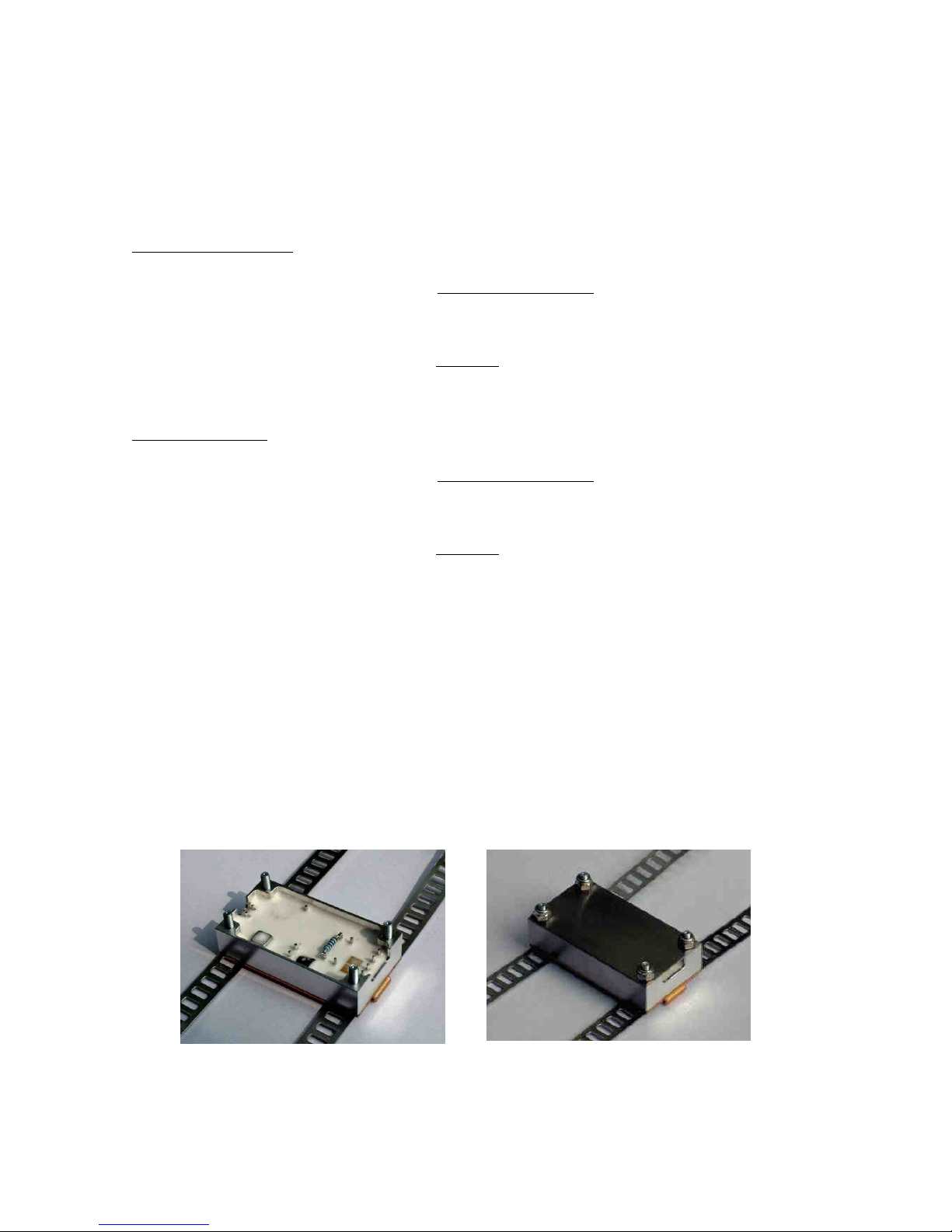
3.1.3 TX31D/1/IFM Mounting and Cover Plate
The TX31D/1/IFM can be mounted on a plate surface by using M3 bolts through the 4 corner holes or it may be fixed
o
nto a shaft using the strapping attachment plate included in the CAK kit.
If the transmitter is inductively powered a mu metal cover plate may be required. This is necessary when the transmitter
is close to the pickup head IH2 or loop IL2. Failure to do this may result in a zero shift once per revolution, due to
inductive power magnetic field pickup.
To minimise noise levels and stray signal pickup;
1. Use screened cable for the strain gauge leads
2. Fit the supplied mu metal cover to screen the transmitter circuitry
3. Connect the signal cable screen to transmitter housing
4. Ground the transmitter to the shaft
1024 x Gauge Resistance
Required Signal in mV
Calibration Resistor in Ohms =
- (0.5 x Gauge Resistance)
1024 x 350
2 mV
- (0.5 x 350)
Calibration Resistor in Ohms =
= 179,025 ohms
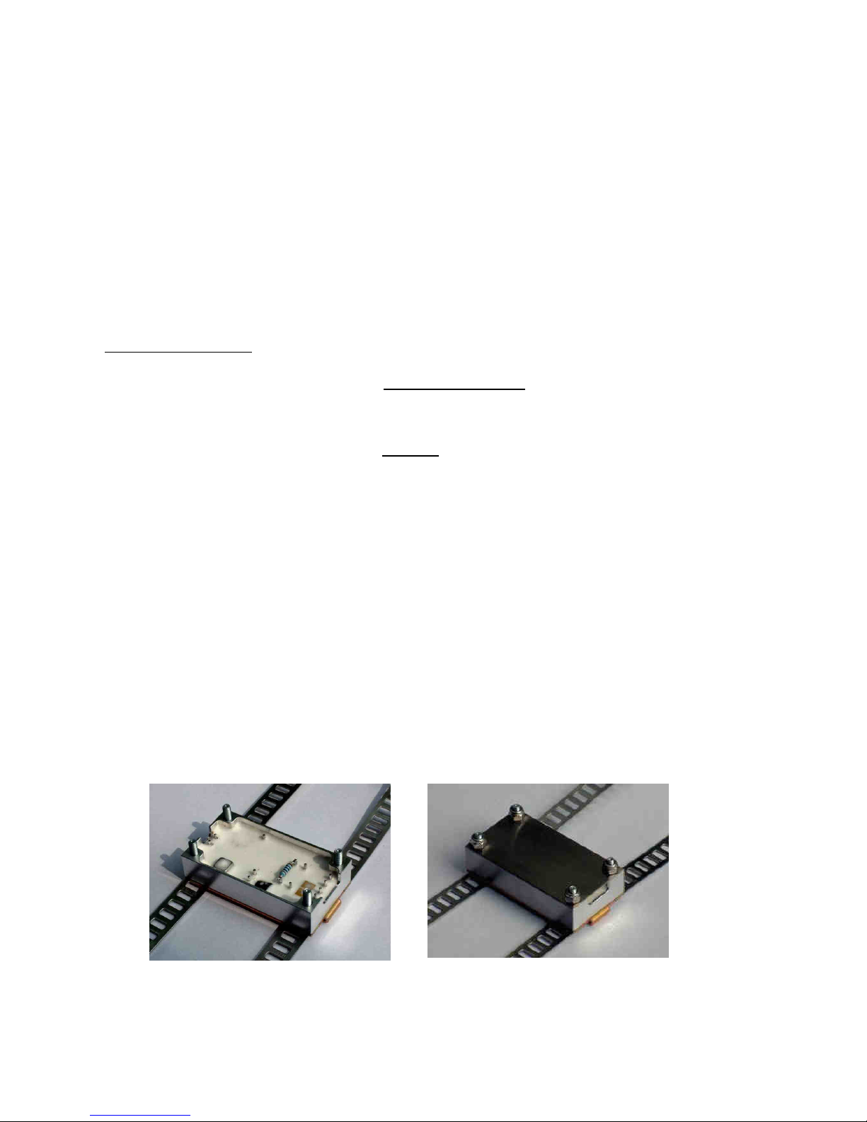
Figure 2 – TX31D with Strapping Plate and Mu Metal Cover
1250 x Gauge Resistance
Required Signal in mV
Calibration Resistor in Ohms =
- (0.5 x Gauge Resistance)
1250 x 350
2 mV
- (0.5 x 350)
Calibration Resistor in Ohms =
= 218,575 ohms
Page 10

TM Page 10
3.1.4 TX31D/1/IFM Specifications
I
nput: 1 channel full bridge strain gauge input. "Instrumentation Amp" input, operating at
2.048V common-mode (set by strain gauge bridge common-mode). Series and
common-mode input resistance 20 M ohms. Input bias current 1 nA. Input sensitivity
set by single user accessible resistor. Range 0.1 mV to 500 mV full scale.
Bridge Excitation Supply: 4.096VDC ±1% (5VDC from 1/1/2006) over full operating temperature range. Voltage
temperature coefficient typically 20 ppm / °C. Max imum bridge output current 40 mA.
Short circuit protected.
Zero Shift with Temperature: Typically 0.03 %/°C.
Resolution & Accuracy: 11 bits plus sign, 0.1% full range.
Operating Temperature Range: -50 °C to +120 °C. Ext ended range to special order.
Power Requirement: 6 - 12 VDC @ 9 mA plus bridge current.
Dimensions: 52 mm x 27mm x 11 mm
Weight: Transmitter only 24 grams. With strapping plate and mu metal cover 56 grams
Construction: Encapsulated in epoxy resin within machined aluminium housing
Page 11
TM Page 11
3.2 TRANSMITTER TX34/1/IFM
The single channel (plus power supply monitor and internal temperature channels) TX34D/1/IFM transmitter is a compact,
low profile design, used when a minimum diameter for the shaft mounted hardware is required. The lightweight machined
aluminium housing is drilled to accept a screening cover and slotted base-plate fixture (for use with the shaft clamp
assembly kit CAK). Power supply is normally by inductive coupling into a single turn pickup loop, either wound around the
shaft periphery (and separated from the shaft by an insulating standoff layer), or located within a groove machined into the
split-ring assembly O.D. The transmitter may also be powered by batteries. For example, two ½ AA size lithium cells
usually housed within a TX.MTGS split ring assembly, or the TX31 battery unit.
Circuitry consists of an input filter followed by a programmable instrumentation amplifier, stabilised bridge excitation supply
of 4.096VDC, 16 bit A/D converter plus control logic, rectification circuitry to convert the incoming AC inductive power to
filtered DC (not used if battery powered) and finally, a 10.7 MHz fm output stage. The input amplifier gain controls the
overall system sensitivity and is set by the RE3D sending control pulses via the inductive power supply. A remote shunt
calibration facility is incorporated into the input stage and is activated by a command from the RE3D. A shunt calibration
resistor is connected across one arm of the strain gauge input circuit for a period of 10 seconds, this is either a DC or AC
signal at various frequencies. The shunt calibration resistor is user fitted across two solder pins.
Signal transmission is by inductive coupling of the 10.7MHz f.m. carrier from a single-turn loop wound around the shaft (in
an inductively powered system this loop also collects power) and an inductive head IH1 (IH2 or inductive loop IL2 for
inductively powered transmitters). Transmission range is typically 50-200mm, reducing to 10-15mm for inductively powered
transmitters, this being the maximum airgap across which sufficient electrical power for the transmitter can be transferred.
In construction, the transmitter circuitry is encapsulated in epoxy resin within a machined aluminium housing with solder
pins providing the input connections to the strain gauge leadwires, inductive power/pickup loop and shunt calibration
resistor. The transmitter housing is drilled with 4 x M3 clearance holes for attachment of the screening cover and mounting
baseplate.
P1
P2
P3
P4
P5 P6
P8
P9
P7
P10
P11
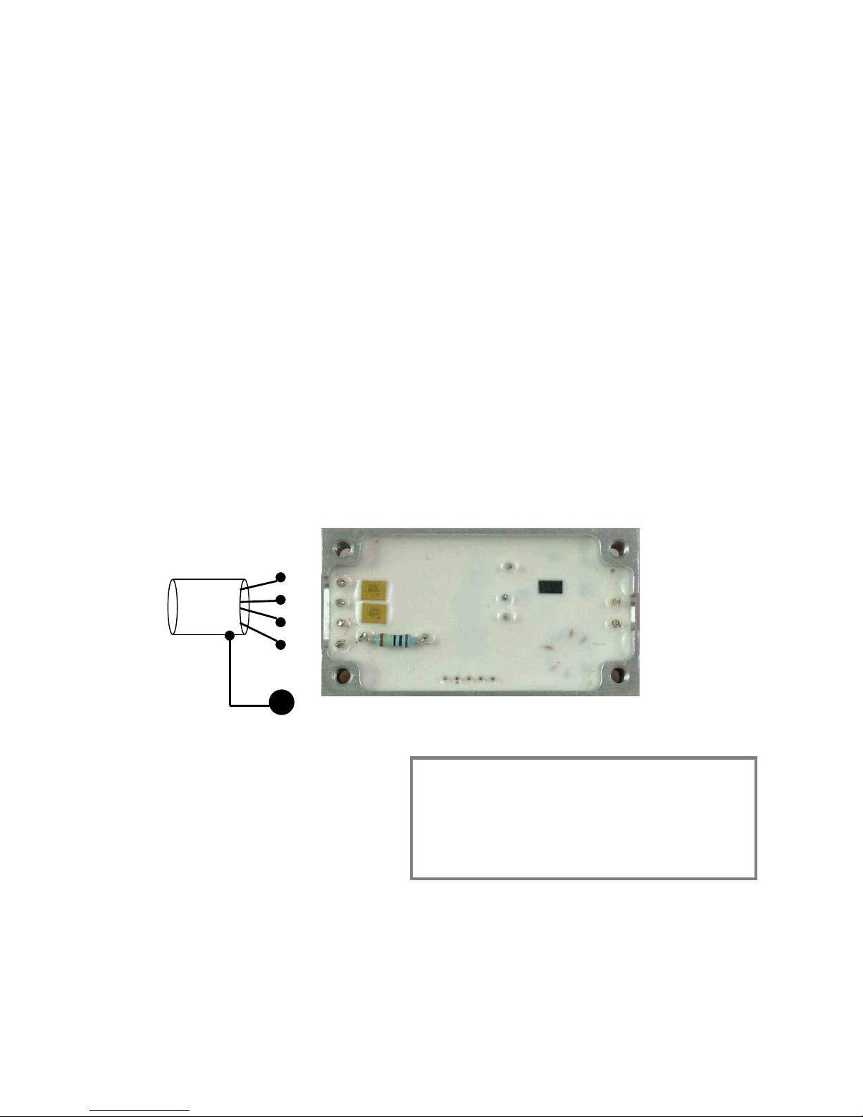
Figure 3 - TX34D/1/IFM Transmitter Connections
P1= +4.096V EX
P2= + SIG
P3= - SIG
P4= 0V EX
P5= R cal
P6= R cal
P7= PCM TEST
P8= +V IN
P9= 0V & HOUSING
P10= LOOP ANT
P11= LOOP ANT
IF THE TRANSMITTER IS CLOSE TO INDUCTIVE HEAD:
1) Use screened cable for gauge leads
2) Fit supplied metal cover to screen transmitter circuitry
3) Connect signal cable screen to transmitter housing
Failure to do this may result in a zero shift once per
revolution due to inductive power magnetic field pickup
Page 12
TM Page 12
3.2.1 TX34D/1/IFM Input Connections & Scaling
Input sensitivity of the transmitter input is set by a sending a command from the RE3D demodulator unit. This sets the gain
o
f the input amplifier as required by sending a command over the inductive power supply. Signal source offsets can also be
removed by the programmable amplifier, this again is controlled by the RE3D.
3.2.2 TX34D/1/IFM Calculation of Shunt Calibration Resistor "Rcal"
Two solder pins P5 and P6 are provided for the incorporation of a user fitted shunt calibration resistor (Rcal). The shunt
c
alibration facility is incorporated into the input stage and is activated by a command from the RE3D. A shunt calibration
resistor is connected across one arm of the strain gauge input circuit for a period of 10 seconds, this is either a DC or AC
signal at various frequencies. The shunt calibration resistor is user fitted across two solder pins. The micro-controller in the
transmitter switches the resistor between "0VEX" and "-SIG" pins for 10 seconds. This feature is mainly suitable for
inductively powered transmitters, since the command can be sent whilst the shaft is rotating, providing a "Remote
Calibration" facility. Required value for the calibration resistor Rcal, may be calculated from the following equation. The
calculation can also be done using the Strain Tx Setup – Cal Resistor menu in the RE3D.
Transmitters with 4.096VEx
For example;
3.2.3 TX34D/1/IFM Mounting and Cover Plate
T
he TX34D/1/IFM uses the TX31D/1/IFM mounting system as they share the same housing. The TX34D/1/IFM can be
mounted on a plate surface by using M3 bolts through the 4 corner holes or it may be fixed onto a shaft using the
strapping attachment plate included in the CAK kit.
If the transmitter is inductively powered a mu metal cover plate may be required. This is necessary when the transmitter
is close to the pickup head IH2 or loop IL2. Failure to do this may result in a zero shift once per revolution, due to
inductive power magnetic field pickup.
To minimise noise levels and stray signal pickup;
5. Use screened cable for the strain gauge leads
6. Fit the supplied mu metal cover to screen the transmitter circuitry
7. Connect the signal cable screen to transmitter housing
8. Ground the transmitter to the shaft
1024 x Gauge Resistance
Required Signal in mV
Calibration Resistor in Ohms =
- (0.5 x Gauge Resistance)
1024 x 350
2 mV
- (0.5 x 350)
Calibration Resistor in Ohms =
= 179,025 ohms
Figure 4 – TX31D with Strapping Plate and Mu Metal Cover
Page 13

TM Page 13
3.2.4 TX34D/1/IFM Specifications
I
nput: 1 channel full bridge strain gauge input. "Instrumentation Amp" input, operating at
2.048V common-mode (set by strain gauge bridge common-mode). Series and
common-mode input resistance 20 M ohms. Input bias current 1 nA. Input sensitivity
set by remote programming using the RE3D. Range 0.1 mV to 500 mV full scale.
Bridge Excitation Supply: 4.096VDC ±1% over full operating temperature range. The Voltage temperature
coefficient is typically 20 ppm / °C. Maximum brid ge output current 40 mA. Short circuit
protected.
Zero Shift with Temperature: Typically 0.03 %/°C.
Resolution & Accuracy: 15 bits plus sign, 0.1% full range.
Operating Temperature Range: -50 °C to +120 °C. Ext ended range to special order.
Power Requirement: 6 - 12 VDC @ 9 mA plus bridge current.
Dimensions: 52 mm x 27mm x 11 mm
Weight: Transmitter only 24 grams. With strapping plate and mu metal cover 56 grams
Construction: Encapsulated in epoxy resin within machined aluminium housing
Page 14
TM Page 14
3.3 TRANSMITTER TX35/1/IFM
The single channel (plus power supply monitor and internal temperature channels) TX35D/1/IFM transmitter is a miniature,
l
ow profile design, used when a minimum diameter for the shaft mounted hardware is required. The transmitter is
encapsulated in a high temperature epoxy resin. The power supply is normally by inductive coupling into a single turn
pickup loop, either wound around the shaft periphery (and separated from the shaft by an insulating standoff layer), or
located within a groove machined into the split-ring assembly O.D. The transmitter may also be powered by batteries, for
example, one lithium cells at 3.7V can be used.
Circuitry consists of an input filter followed by a programmable instrumentation amplifier, stabilised bridge excitation supply
of 3.0DC, 16 bit A/D converter plus control logic, rectification circuitry to convert the incoming AC inductive power to filtered
DC (not used if battery powered) and finally, a 10.7 MHz fm output stage. The input amplifier gain controls the overall
system sensitivity and is set by the RE3D sending control pulses via the inductive power supply. A remote shunt calibration
facility is incorporated into the input stage and is activated by a command from the RE3D. A shunt calibration resistor is
connected across one arm of the strain gauge input circuit for a period of 10 seconds, this is either a DC or AC signal at
various frequencies. The shunt calibration resistor is user fitted across two solder pins.
Signal transmission is by inductive coupling of the 10.7MHz f.m. carrier from a single-turn loop wound around the shaft (in
an inductively powered system this loop also collects power) and an inductive head IH1 (IH2 or inductive loop IL2 for
inductively powered transmitters). Transmission range is typically 50-200mm, reducing to 10-15mm for inductively powered
transmitters, this being the maximum airgap across which sufficient electrical power for the transmitter can be transferred.
In construction, the transmitter circuitry is encapsulated in epoxy resin with solder pins providing the input connections to
the strain gauge leadwires, inductive power/pickup loop and shunt calibration resistor.
P9
P10
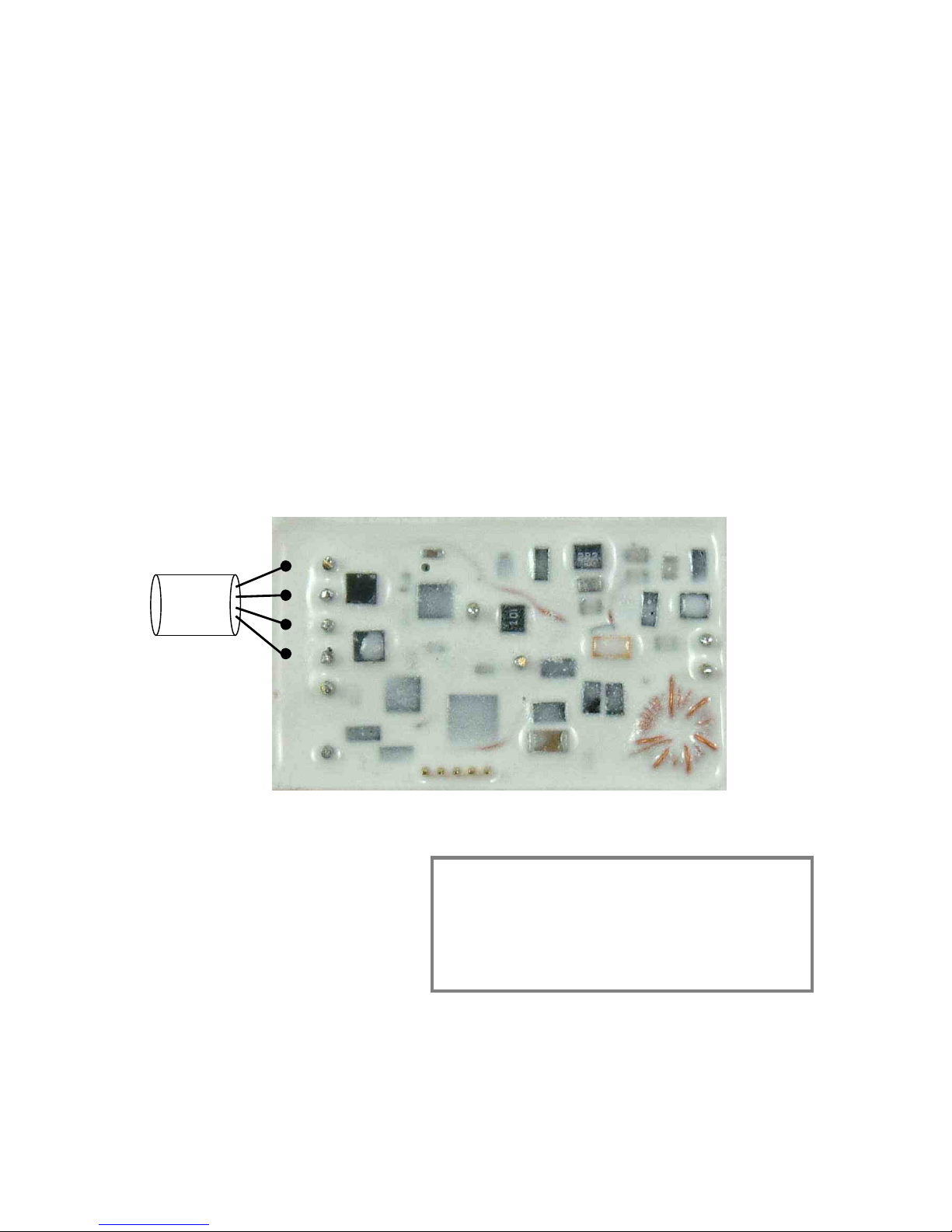
Figure 5 - TX35D/1/IFM Transmitter Connections
P1= +4.096V EX
P2= + SIG
P3= - SIG
P4= 0V EX
P5= R cal
P6= R cal
P7= 0V
P8= +V IN
P9= LOOP ANT
P10= LOOP ANT
IF THE TRANSMITTER IS CLOSE TO INDUCTIVE HEAD:
1) Use screened cable for gauge leads
2) Fit supplied metal cover to screen transmitter circuitry
3) Connect signal cable screen to transmitter 0V
Failure to do this may result in a zero shift once per
revolution due to inductive power magnetic field pickup
P1
P2
P3
P4
P8
P5
P6
P7
Page 15

TM Page 15
3.3.1 TX35D/1/IFM Input Connections & Scaling
Input sensitivity of the transmitter input is set by a sending a command from the RE3D demodulator unit. This sets the gain
o
f the input amplifier as required by sending a command over the inductive power supply. Signal source offsets can also be
removed by the programmable amplifier, this again is controlled by the RE3D.
3.3.2 TX35D/1/IFM Calculation of Shunt Calibration Resistor "Rcal"
Two solder pins P5 and P6 are provided for the incorporation of a user fitted shunt calibration resistor (Rcal). The shunt
c
alibration facility is incorporated into the input stage and is activated by a command from the RE3D. A shunt calibration
resistor is connected across one arm of the strain gauge input circuit for a period of 10 seconds, this is either a DC or AC
signal at various frequencies. The shunt calibration resistor is user fitted across two solder pins. The micro-controller in the
transmitter switches the resistor between "0VEX" and "-SIG" pins for 10 seconds. This feature is mainly suitable for
inductively powered transmitters, since the command can be sent whilst the shaft is rotating, providing a "Remote
Calibration" facility. Required value for the calibration resistor Rcal, may be calculated from the following equation. The
calculation can also be done using the Strain Tx Setup – Cal Resistor menu in the RE3D.
Transmitters with 3.0Ex
For example;
3.3.3 TX35D/1/IFM Specifications
I
nput: 1 channel full bridge strain gauge input. "Instrumentation Amp" input, operating at 1.5V
common-mode (set by strain gauge bridge common-mode). Series and common-mode
input resistance 20 M ohms. Input bias current 1 nA. Input sensitivity set by remote
programming using the RE3D. Range 0.1 mV to 500 mV full scale.
Bridge Excitation Supply: 3.0VDC ±1% over full operating temperature range. Voltage temperature coefficient
typically 20 ppm / °C. Maximum bridge output curre nt 40 mA. Short circuit protected.
Zero Shift with Temperature: Typically 0.03 %/°C.
Resolution & Accuracy: 15 bits plus sign, 0.1% full range.
Operating Temperature Range: -50 °C to +120 °C. Ext ended range to special order.
Power Requirement: 3.3 - 12 VDC @ 9 mA plus bridge current.
Dimensions: 35mm x 20mm x 5mm
Weight: Transmitter only; 6 grams.
Construction: Encapsulated in high temperature epoxy resin
750 x Gauge Resistance
Required Signal in mV
Calibration Resistor in Ohms =
- (0.5 x Gauge Resistance)
750 x 350
2 mV
- (0.5 x 350)
Calibration Resistor in Ohms =
= 131,075 ohms
Page 16
TM Page 16
4 DEMODULATOR RE3D
T
he RE3D Demodulator is a highly sophisticated unit that can output digital and analogue data collected from a variety of
transmitter types. The built in microcontrollers allow onboard computation of strain and power directly from mechanical
parameters entered into the unit from the front panel or using a PC/laptop via a USB interface. For compatible transmitters,
eg TX34D/TX35D, the RE3D can also be used to set the gain, offset and calibration.
Circuitry and hardware comprising of a 10.7MHz demodulator, pcm decoder and analogue output conditioning circuitry –
digital zero and output level trimmers, signal status indicators etc., are contained within a compact extruded aluminium
enclosure type RE. An inductive power supply oscillator, which replaces batteries as the transmitter power source, is also
incorporated. This can be disabled allowing battery powered transmitters to be used. The power supply is highly flexible
allowing the unit to be powered by either a 9-30VDC source at 1A or a 90-260VAC mains voltage.
In operation the unit circuitry firstly amplifies the low-level 10.7MHz fm signal (received at the inductive head or loop), then
demodulates it to recover the transmitted serial pcm. This is then scaled digitally before being output to the analogue
voltage stage. Output conditioning circuitry provides filtering, zero adjustment and output level adjustment. Maximum
output levels are ± 10V. A tachometer input allows shaft RPM to be displayed. Valid data reception is indicated by the
presence of a front panel red ‘Error’ LED. Depending on the transmitter type various signals can be output. For example,
using a TX34D or TX35D allows the display and output of strain, power, transmitter power supply voltage and transmitter
temperature.
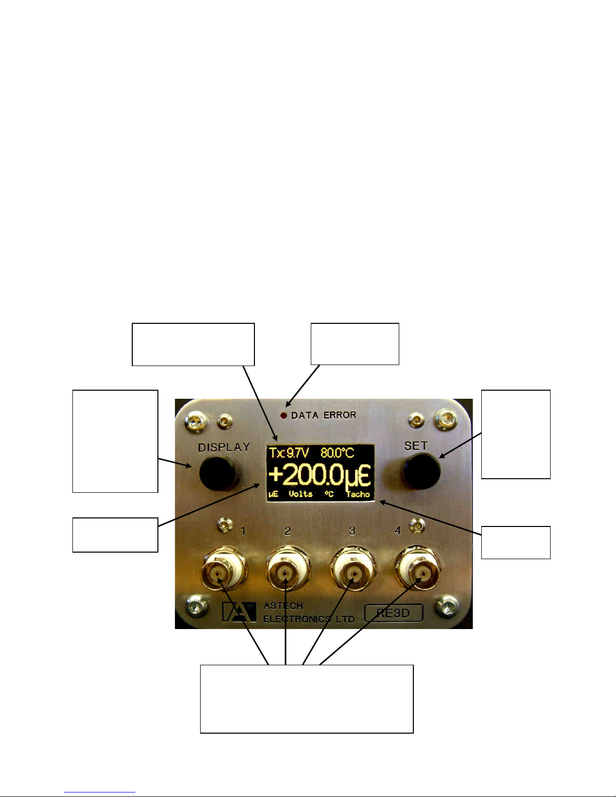
4.1 RE3D FRONT AND REAR PANELS
Red LED - On
when good data is
not being received
Press to
select setting
to change.
Turn to alter
and the press
to keep
changes
Analogue Outputs. Any data type can be output
on any channel. For example torque,
Transmitter supply volts, RPM and Power. Each
output selectable ±0V TO ± 10V or unipolar for
connection for various data loggers.
Turn to alter the
displayed data.
Press to enter
menu selection.
Press and hold
for two seconds
to return to return
to display mode.
Transmitter power supply
voltage and ambient
temperature
Strain data from
transmitter.
Analogue
output type.
Page 17
TM Page 17
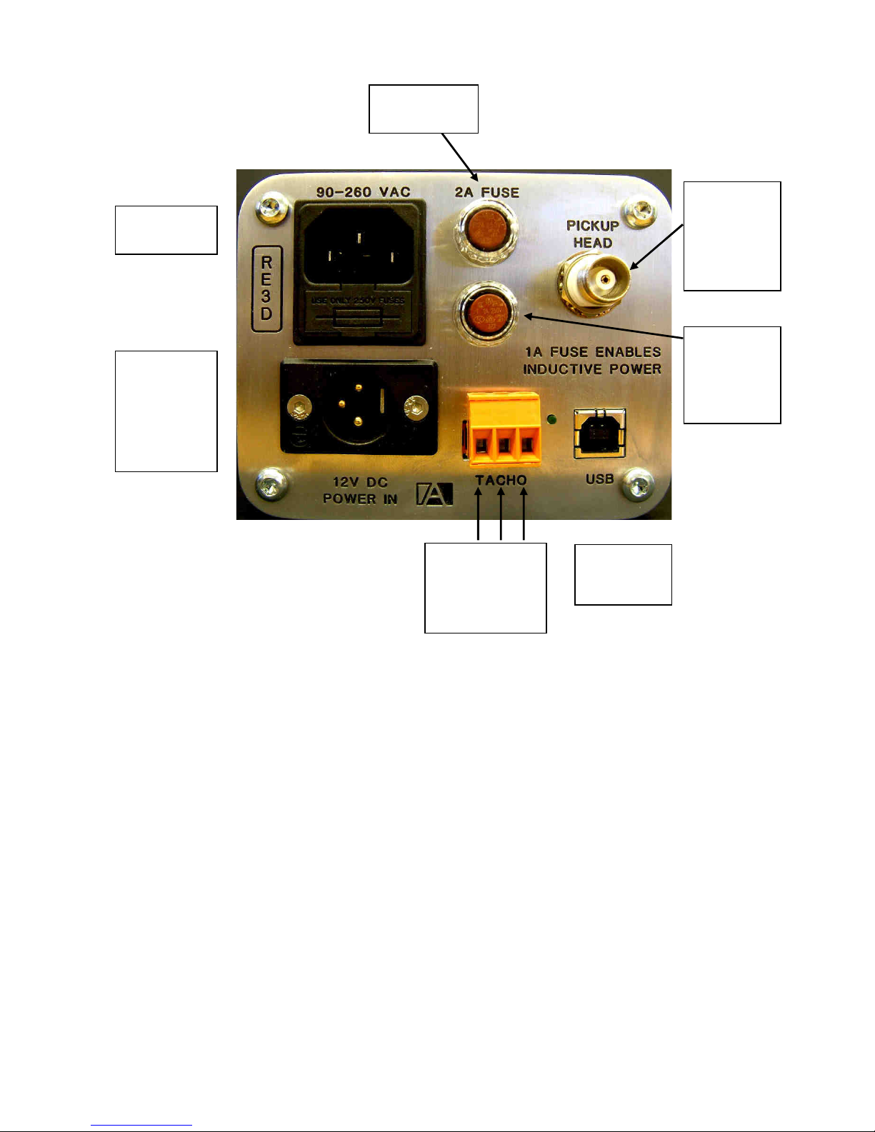
Connect to
inductive
head IH1, IH2
or IL2 with
supplied
coaxial cable
Connect to
9-30VDC
SUPPLY (Free
plug supplied).
P1= +V,
P2= 0V.
Figure 6 - Demodulator RE3D Controls & Connections
Mains input.
90-260VAC
Main input fuse
2A Slow Blow
Remove 1A
fuse to
disable the
Inductive
power supply
+12V Sig 0V
Tachometer Input
and LED to show
tachometer active
USB
connection to
PC or Laptop.
Page 18

TM Page 18
4.2 RE3D CONTROLS & CONNECTIONS
R
otary Encoders: The Display and Set rotary encoders are used to control all settings of the RE3D. The
Display encoder is used to change the information shown on the display. Various options
are available; a summary screen, large character display of strain, transmitter temperature,
transmitter supply volts etc. Pressing the Display encoder brings up the Program menu.
Each main heading can be expanded or collapsed by pressing the encoder. When the unit
is in any program menu pressing the Display encoder for 2 seconds will return to the data
Display screen.
The Set encoder is used alter any of the programmable settings and control the function of
the RE3D. Press the Set encoder to select the number to be changed, turn the encoder to
alter the amount and press again to exit setting. For example, to change the number of
teeth used by the tachometer. Press the Display encoder for enter the program menu and
turn to the Tachometer Settings option. Press again to expand the menu and select Tacho
Flags. Press the display encoder again to enter setting menu. Now turn the Set encoder to
select the digit to be changed and press Set again to change it. The digit will now be
highlighted and change altered by turning the Set encoder. When the desired number is
displayed press Set to exit the alter mode and allow the next digit to be selected. Once the
desired number of teeth has been entered press Display to return to the Program menu or
press and hold for 2 seconds to return to the data Display screen.
O/P Output(s): This is a standard BNC socket and is the signal output. Full scale for Strain data can be set
to various output levels, for example ±5V, ±10V, 0-5V 0-10V etc. The outputs can also be
set to allow analogue logging or monitoring of the transmitter temperature and display volts.
Data Error LED: The red DATA ERROR led will light when invalid data is received from the transmitter. This
is an excellent indication of signal integrity and system function as a micro controller is
constantly checking the received signal to ensure that uncorrupted data is present. Only
then is the DATA ERROR led extinguished. This led is always active, even when the unit is
in program mode.
12VDC Power Connector: Power supply input connector. Nominal 12VDC at 1A. Pin 1 = +12V, Pin 2 = Ground.
Input voltage range is 9 – 36VDC allowing the RE3D to be powered from 24V automotive
supplies.
IEC Power Connector: Mains AC Power supply input connector. 85 – 264 VAC @ 47 – 440 Hz.
Fuses: European type TR5. Main fuse 2A Anti Surge. Inductive power fuse 1A Anti Surge. This
fuse only powers the inductive power supply in the RE3D. Removing the fuse enables the
unit to be used with the inductive head type IH1 (IH1 type is signal pickup only - no
inductive power) for maximum pickup range with a battery-powered transmitter.
Pickup Head TNC This is connected to the inductive pickup head or loop, IH1, IH2 or IL2. For use with the IH1
the fuse MUST be removed – see above. The TNC connector is a screw version of the
BNC connector. DO NOT POWER THE UNIT WITH THE INDUCTIVE POWER ENABLED
(fuse in) AND NO HEAD CONNECTED.
4.2.1 RE3D Specifications
Bandwidth: D
C to 1000Hz.
Linearity: ±1 bit.
Zero Stability RTO: ±0.5 mV/°C
Output Noise Level: 3.5mV RMS at maximum output level setting (±5V output setting).
External Adjustments/Controls: 1). 10 turn locking dial- ZERO.
2). 10 turn locking dial- OUTPUT LEVEL adjust.
3) Remote Cal Pushbutton (RE2D/IFM/2 only)
Power Requirement: 12VDC @ 0.15A (No inductive power), @ 0.85A (With inductive power).
Operating Temperature: -20 °C to +60 °C.
Page 19

TM Page 19
Physical: C
lear anodised aluminium enclosure 220 x 105 x 82mm excluding connectors.
Weight 1.2Kg.
Fuse: European type TR5, 2A Anti surge.
Page 20

TM Page 20
4.3 RE3D PROGRAMING
4.3.1 Programming Notes
T
he RE3D is a highly configurable device. Using the rotary encoders and display allows the unit to be setup to perform
many measurement tasks. For instance the output from a strain gauge bridge can be displayed directly in µε or the
reading can be scaled to display torque in Nm. Alternatively the scaling can be set to display any arbitrary value, for
instance a % of safe working load, load in Kg etc.
The analogue outputs can be scaled to suit any data logger input range and the type of output can be set as required,
for instance is may be desired to log torque and transmitter temperature. If a tachometer added not only can the shaft
rpm be displayed and output but the shaft power also.
In fact the RE3D is ideally suited to measuring torque or power on any rotating shaft as the mechanical properties of the
shaft can be entered allowing the RE3D to calculate Strain and, if a tachometer is used, also Power. This allows a shaft
torque to be measured without having to remove and calibrate the shaft in a torque rig.
To setup the RE3D the correct transmitter type must first be selected. The available menus will change depending on the
functions available in the particular transmitter.
Next the correct input type must be selected, again the available menus will change depending on the functions available
for the particular input type selected. Note that for a transmitter with programmable gain (TX34D, TX35D etc) the gain is
calculated and can be sent to the transmitter, for a transmitter with resistor set gain (TX31D etc) the gain is calculated and
the correct gain set resistor value is displayed.
The input type options are;
1/. Strain Transducer For connection to a strain transducer, for example a load cell. The default output is µε.
Settings are mV/V and µε full scale. The calculated gain required is displayed and
calibration resistor value can be calculated.
2/. Torque Transducer For connection to a torque transducer with a known mV/V output. The default output is Nm.
Settings are mV/V and torque full scale. The calculated gain required is displayed and
calibration resistor value can be calculated.
3/. Torque Shaft For connection to a torque shaft without a known mV/V output. Allows the physical
properties of the shaft to be entered and torque calculated from these. The default output is
Nm. Settings are torque full scale, gauge factor, number of active gauges, shaft external
and internal diameter, the shaft material young’s modulus and poisons ratio. The calculated
gain required is displayed and calibration resistor value can be calculated.
4/. Strain Bridge For connection to a strain bridge. The default output is µε. Settings are µε full scale, gauge
factor and number of active gauges. The calculated gain required is displayed and
calibration resistor value can be calculated.
5/. Manual Allows the gain to set manually. The calculated gain required is displayed and calibration
resistor value can be calculated. For a transmitter with resistor set gain (TX31D etc) the
calculated gain set resistor value is displayed.
Once the transmitter input is set any further settings can be done from the TX Control menu. This will be different for each
transmitter type. For example the TX34D allows the following to be set; one of several calibration signals can be selected,
any offset can be removed, the input can be inverted (useful if the signal pins of a bridge have accidently reversed), the
settings summary can be viewed, the Rf frequency can be adjusted if required.
After setting up the transmitter the input analogue outputs required are set. Several different output options are available
depending on the transmitter type. If a tachometer input is used the power can be displayed and output. The required
analogue output volts can also be selected, examples are ±5V, ±10V, 0-5V 0-10V etc
Any small output gain errors or offset can be removed using the Trim Adjust menu.
The units for the strain output can be set using the Strain Display menu, for example a load cell could have output units of
Kg. Note that the number of decimal points and resolution of the display are set when the full scale value is entered.
If a tachometer is connected to the RE3D the full scale RPM and the number of pulses per revolution can be set.
Page 21

TM Page 21
4.3.2 Setting the Display Resolution
F
or the Strain Transducer and Torque transducer input types the full scale is set in the Transducer mV/V menu item.
For the Torque shaft Input type it is set in the Torque Full Scale menu.
For the Strain Bridge type it is in the µε Full Scale menu.
For example if a Torque Shaft input type is selected, setting the Torque Full Scale to +00200.0 will set the full scale output
analogue voltage to be full scale for a shaft torque of 200 Nm but will also set the RE3D display to show +/-200Nm with a
resolution of 0.1Nm. Setting the Torque Full Scale to +002000. will again set the full scale output analogue voltage to be
full scale for a shaft torque of 200 Nm but the RE3D display will now show +/-200Nm with a resolution of 1Nm.
4.3.3 Program Flow Charts
T
he following pages show the flow charts for typical transmitters;
Page 22
TM Page 22
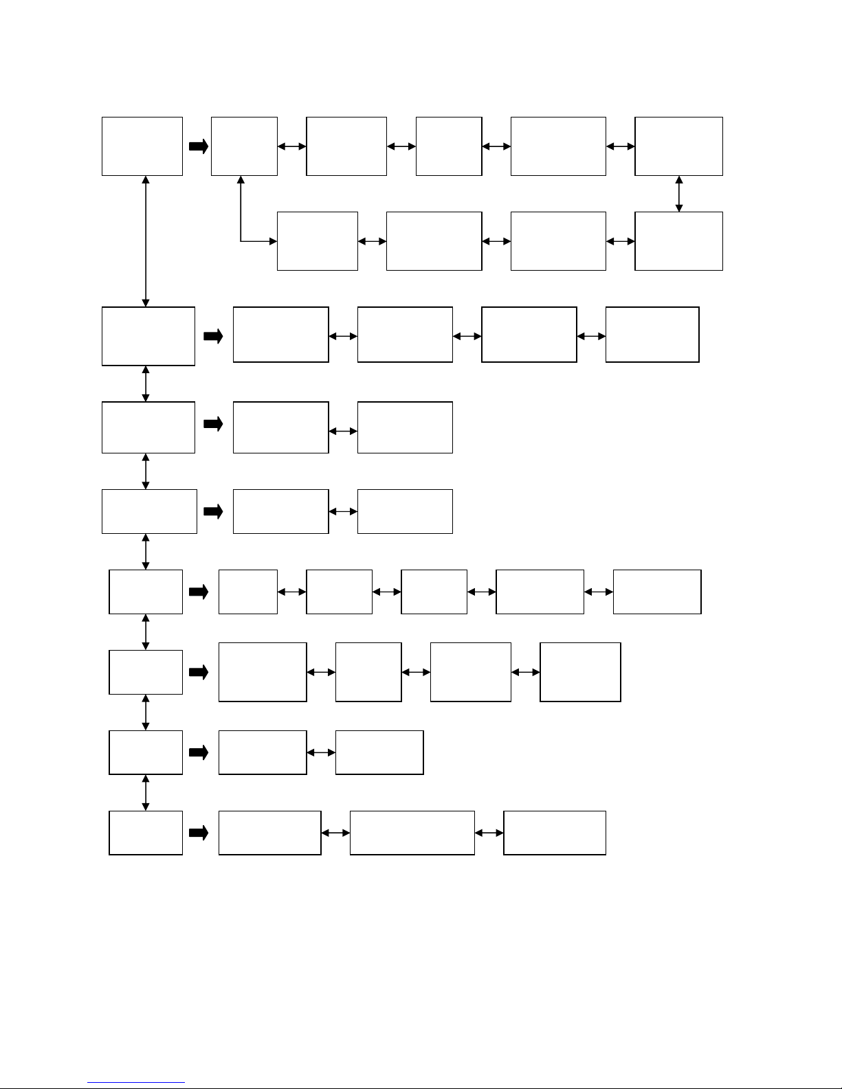
4.3.3.1 RE3D With TX34D Transmitter
Display
Strain
Display Tx
Supply
Volts
Display
Tx
Temp
Analogue
Outputs
Display Tx
Amplifier
Error Status
Display Tx
Calibration
Mode
Display Tx
Serial
Number
Display
Demodulator
Error Count
Display
Tachometer
Speed
Display
Shaft
Power
Display
Output 1 Output 2 Output 3 Output 4
Trim Adjust Strain Zero
trim
Strain Gain
Trim
Strain
Display
Strain Units Scaling
Strain Tx
Setup
uE Full
Scale
Gauge
Setup
Calculated
Gain
Calibration
Resistor
TX34
Control
TX34
Calibration
Mode
TX34
Zero
Adjust
TX34
Input
Invert
Tacho
Settings
Tacho
Flags
Decoder
Settings
Transmitter
Types
Output Calibration
mode
OLED Display
Brightness
Input
Type
Full Scale
RPM
Show
TX34
Setup
Page 23
TM Page 23
4
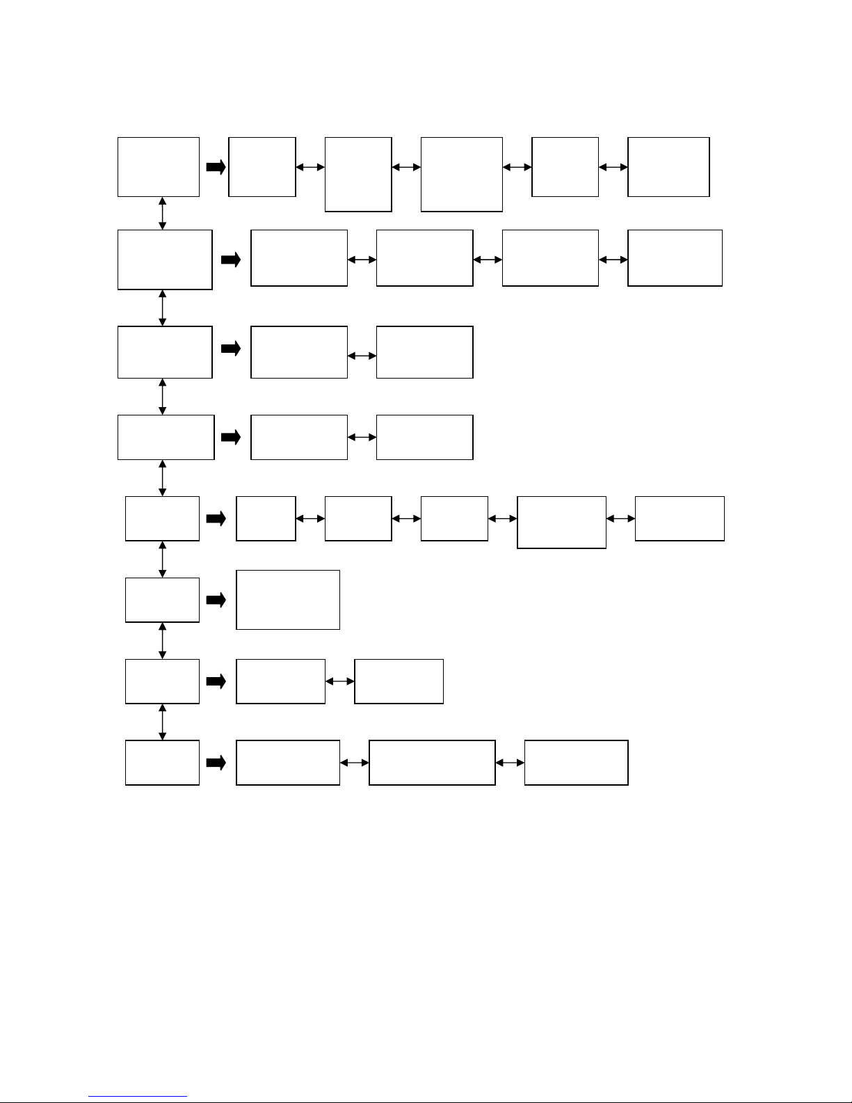
.3.3.2 RE3D With TX31D Transmitter
Display
Strain
Display
Tx
Supply
Volts
Analogue
Outputs
Display
Demod
Error
Count
Display
Tacho
Speed
Display
Shaft
Power
Display
Output 1 Output 2 Output 3 Output 4
Trim Adjust Strain Zero
trim
Strain Gain
Trim
Strain
Display
Strain Units Scaling
Strain Tx
Setup
uE Full
Scale
Gauge
Setup
TX31D
Gain
Calibration
Resistor
TX31D
Control
Start TX31D
Calibration
Mode
Tacho
Settings
Tacho
Flags
Decoder
Settings
Transmitter
Types
Output Calibration
mode
OLED Display
Brightness
Input
Type
Full Scale
RPM
Page 24
TM Page 24
4
.3.4 RE3D Programming Menu
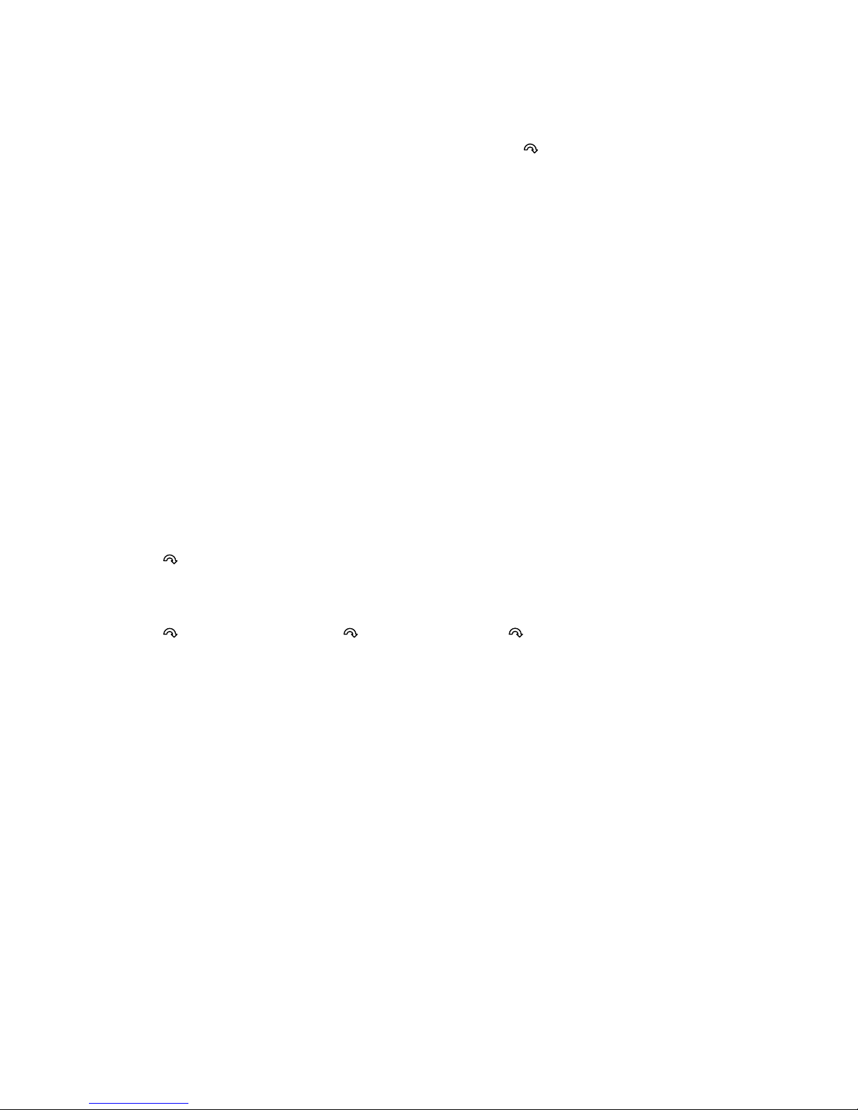
In this section DISPLAY or SET = press the Display or Set rotary encoder, = turn the encoder.
Note that after programming pressing Display will return to the menu and pressing and holding the encoder for 2
seconds will return to the main display screen.
To alter numbers such as the Strain Zero Trim in the Trim Adjust menu;
Turn the Set encoder to select the digit to be changed. Press the Set encoder to highlight the digit. Turn to select the
correct value and then press Set again. Select another digit to change by turning the Set encoder. Note that the
position of the decimal point can be altered by highlighting it and then moving it by turning the Set encoder. Press Set
again to position it permanently.
4.3.5 Display Menu
T
his is used to select the main display screen. The display screen can also be changed by turning the Display Rotary
Encoder.
The Display screens available are;
Tx Strain
Tx Supply Volts
Tx Temperature
Tx Amp Status
Tx Serial Number
Decoder Error Counts
Tachometer Speed
Shaft Power
DISPLAY, Select required display, DISPLAY
4.3.6 Analogue Outputs Menu
D
ISPLAY, Analogue Outputs, DISPLAY, Output x, DISPLAY, SET, Output and Range. DISPLAY
Select the required output for each analogue output BNC. Note that the options available will change depending on the
transmitter type. For the TX34D/35D the outputs are;
Strain, Tx Supply V, Tx Temperature, Tachometer, Power.
The available full scale output voltage ranges are;
0 ~ 1V (Positive only, no negative output even if sensor output negative)
0 ~ 5V (Positive only, no negative output even if sensor output negative)
0 ~ 10V (Positive only, no negative output even if sensor output negative)
-1 ~ 0 ~ 1V (±1V)
0.5 ~ 2.5 ~ 4.5 (±2V offset by 2.5V)
0 ~ 2.5 ~ 5 (±2.5V offset by 2.5V)
0 ~ 5 ~ 10 (±5V offset by 5V)
-5 ~ 0 ~ 5V (±5V)
-10 ~ 0 ~ 10V (±10V)
This allows the RE3D to be interfaced to practically any available data logger input.
Page 25
TM Page 25
4.3.7 Trim Adjust Menu
T
his is used to make scaling adjustments to the strain gain and offset. For non programmable transmitters such as the
TX31D zero offsets are removed here. Any scaling errors due to a non perfect gain set resistor can be removed using
the Gain trim.
This is also useful if a programmable transmitter is being used with a battery and hence no remote programming can be
used.
4.3.7.1 Strain Zero trim
D
ISPLAY, Trim Adjust, DISPLAY, Strain Zero Trim, DISPLAY, SET, Set Zero Trim. DISPLAY
The maximum value of the Zero Trim is ±19.999%
4.3.7.2 Strain Gain trim
D
ISPLAY, Trim Adjust, DISPLAY, Strain Gain Trim, DISPLAY, SET, Set Gain Trim. DISPLAY
The maximum value of the Gain Trim is ±119.999%
4.3.8 Strain Display Menu
T
his is used to set the units of the display, eg kg, Nm etc. If an input type selected in the Strain Tx Setup menu has a
default setting this will be used as standard but may be altered.
The scaling is used to set the 0 and full scale output display. This allows a sensor to display real world units, for instance a
load cell could directly display grams etc.
4.3.8.1 Strain Units
D
ISPLAY, Strain Display, DISPLAY, Strain Units, DISPLAY, SET, Select Default or Custom DISPLAY
If Custom is selected the annotation can be edited in the usual way.
4.3.8.2 Strain scaling
DISPLAY, Strain Display, D
ISPLAY, Scaling, DISPLAY, SET, Set 0% and 100% DISPLAY
4.3.9 Strain Transmitter Setup
This is used to setup the transmitter, including the type of sensor connected, the full scale range and transmitter gain,
calibration resistor etc.
4.3.9.1 Input type
Se
veral different types of input type can be selected.
DISPLAY, Strain Tx Setup, DISPLAY, Input Type, DISPLAY, SET, Select input type. DISPLAY
Strain Transducer For connection to a strain transducer, for example a load cell. The default output is µε. Settings
are mV/V and µε full scale. The calculated gain required is displayed and calibration resistor value
can be calculated.
Torque Transducer For connection to a torque transducer with a known mV/V output. The default output is Nm.
Settings are mV/V and torque full scale. The calculated gain required is displayed and calibration
resistor value can be calculated.
Torque Shaft For connection to a torque shaft without a known mV/V output. Allows the physical properties of
the shaft to be entered and torque calculated from these. The default output is Nm. Settings are
torque full scale, gauge factor, number of active gauges, shaft external and internal diameter, the
Page 26
TM Page 26
shaft material young’s modulus and poisons ratio. The calculated gain required is displayed and
c
alibration resistor value can be calculated.
Strain Bridge For connection to a strain bridge. The default output is µε. Settings are µε full scale, gauge factor
and number of active gauges. The calculated gain required is displayed and calibration resistor
value can be calculated.
Manual Allows the gain to set manually. The calculated gain required is displayed and calibration resistor
value can be calculated. For a transmitter with resistor set gain (TX31D etc) the calculated gain
set resistor value is displayed.
4.3.9.2 Transducer mV/V
U
sed when a transducer or bridge has a known mV/V output. This allows the calibrated value to be directly entered. Note
that the position of the decimal controls how many decimal points are displayed on the front panel display.
DISPLAY, Strain Tx Setup, DISPLAY, transducer mV/V, DISPLAY, SET, Set full scale mV/V. DISPLAY
4.3.9.3 µε
Full Scale
Enter the full scale µε range desired. The gain required to achieve this will be automatically calculated and this can be sent
to programmable transmitters or the required gain resistor is calculated and displayed for resistor programmable types.
Note that the position of the decimal controls how many decimal points are displayed on the front panel display.
DISPLAY, Strain Tx Setup, DISPLAY, µε Full Scale, DISPLAY, SET, Set full scale µε. DISPLAY
4.3.9.4 Calculated Gain
T
he Gain calculated from the entered setup vales is displayed and this can be sent to programmable transmitters by
selecting the Send Now option.
DISPLAY, Strain Tx Setup, DISPLAY, Calculated Gain, DISPLAY, SET, Select Send Now if required.
4.3.9.5 Calibration Resistor
T
he calibration resistor value can be calculated.
DISPLAY, Strain Tx Setup, DISPLAY, Calibration Resitor, DISPLAY, SET, ???.
4.3.9.6 Gauge Setup
F
or input types that require the strain gauge bridge to be setup. The gauge factor (typically 2.00) and the number of active
gauges (eg 4 for a full torque bridge) can be entered.
DISPLAY, Strain Tx Setup, DISPLAY, Gauge Setup, DISPLAY, SET, Set gauge DISPLAY
4.3.9.7 Shaft Size
T
his allows the shaft size to be entered for the Torque Shaft input type to enable torque in Nm to be calculated and
displayed. The outside diameter (OD) and the internal diameter (ID) for a hollow shaft are entered in mm. Enter an ID of 0
for a solid shaft.
DISPLAY, Strain Tx Setup, DISPLAY, Shaft Size, DISPLAY, SET, Set OD and ID DISPLAY
4.3.9.8 Shaft Material
T
his allows the Young’s Modulus and poisons ratio of the shaft material to be entered for the Torque Shaft input type to
enable torque in Nm to be calculated and displayed. The Young’s Modulus is entered in GPa, typical values are; Aluminium
= 69 GPa, titanium = 110 GPa, wrought iron 200 GPa, steel – 200GPa
Poisons ratio is the ratio of strain in the lateral direction to strain in the axial direction, when a tensile stress is applied to a
material. Its value for many solids is close to 1/3. Typical values are; aluminium and titanium 0.33, steel 0.29, magnesium
0.35
DISPLAY, Strain Tx Setup, DISPLAY, Shaft Material, DISPLAY, SET, Set Young’s Modulus and Poisons Ratio
Page 27
TM Page 27
4.3.10 TXxx Control
T
his menu will be different for each transmitter type as different transmitters have different features. Typical menu options
are as follows;
4.3.10.1 TX34 Calibration Mode
D
ISPLAY, TX34 Control, DISPLAY, TX34 Cal Mode, DISPLAY, SET, Set required calibration mode, DISPLAY
The calibration modes for this transmitter are;
Cal Off No calibration mode
DC Shunt Transmitter mounted shunt calibration resistor is connected in parallel across one arm of the
bridge
1KHz AC Shunt Shunt calibration resistor is switched in and out at a rate of 1KHz with a 1:1 mark space ratio
612Hz 1:1 Shunt Shunt calibration resistor is switched in and out at a rate of 612Hz with a 1:1 mark space ratio
612Hz 1:4 Shunt Shunt calibration resistor is switched in and out at a rate of 612Hz with a 1:4 mark space ratio
100Hz AC Shunt Shunt calibration resistor is switched in and out at a rate of 100Hz with a 1:1 mark space ratio
10Hz AC Shunt Shunt calibration resistor is switched in and out at a rate of 10Hz with a 1:1 mark space ratio
4.3.10.2 TX34 Zero Adjust
T
his allows any offset from the input transducer or bridge to removed at the transmitter. This is only available for
programmable type transmitters, eg TX34D, TX35D etc
DISPLAY, TX34 Control, DISPLAY, TX34 Zero Adjust, DISPLAY, SET, Set mV offset, DISPLAY
4.3.10.3 TX34 Input Invert
T
he transducer or bridge input can be inverted at the transmitter if required. This is only available for programmable
type transmitters, eg TX34D, TX35D etc
DISPLAY, TX34 Control, DISPLAY, TX34 Input Invert, DISPLAY, SET, Select Normal or Invert, DISPLAY
4.3.10.4 Show TX34 Setup
D
isplays a summary screen showing the current setup of the transmitter. The gain at each stage, the total gain, the
offset etc are displayed. This is only available for programmable type transmitters, eg TX34D, TX35D etc
DISPLAY, TX34 Control, DISPLAY, TX34 Setup, DISPLAY. Summary screen displayed, DISPLAY
4.3.11 Tachometer Settings Menu
4.3.11.1 Set the Number of Tachometer Flags
D
ISPLAY, Tacho Settings, DISPLAY, Tacho Flags, DISPLAY, SET, Number of flags. DISPLAY
The number of tachometer flags or targets per revolution can be set from 1 to 999.
4.3.11.2 Set the Full Scale RPM
D
ISPLAY, Tacho Settings, DISPLAY, Full Scale RPM, DISPLAY, SET, Set full scale. DISPLAY
The full scale can be set up to 99,999 RPM. This is used to set the analogue range, 0V to full scale. This can be set as 05V or 0-10V etc.
Page 28
TM Page 28
4.3.12 Decoder Settings Menu
4.3.12.1 Set the transmitter type
Pr
ess DISPLAY
Scroll to Decoder Settings
Press DISPLAY
Scroll to Transmitter Type
Press DISPLAY
Press SET
Scroll to select the correct transmitter type
Press DISPLAY to return to the menu or press and hold for 2 seconds to exit the menu and return to the display screen.
DISPLAY, Decoder Settings, D
ISPLAY, Transmitter Type, DISPLAY, SET, correct transmitter type. DISPLAY
4.3.12.2 Set the Output Calibration Mode
DISPLAY, Decoder Settings, D
ISPLAY, Output Calibration Mode, DISPLAY, SET, Calibration mode.
DISPLAY
Modes available are;
4.3.12.3 Set the OLED Display Brightness
D
ISPLAY, Decoder Settings, DISPLAY, Display Brightness, DISPLAY, SET, Brightness. DISPLAY
Page 29

TM Page 29
5 INDUCTIVE POWER SUPPLY & TRANSMITTER INSTALLATION
I
n most applications the shaft or component mounted transmitter is powered via inductive coupling. Inductive coupling uses
the transformer principle to transfer power from a stationary head or loop mounted close to or around the shaft, across an
air-gap and to a second head or loop mounted on the shaft. The term head means a wound coil usually with a ferrite core
to concentrate and shape the magnetic field, and the term loop means a single turn coil, although multiple turn coils may
used in certain applications. As power needs to be transmitted during 360° of shaft rotation at least one of the two
component parts - power transmitting element and power receiving element, needs to be in the form of a loop. In addition
to power transmission the inductive power supply components also transmit the data signal from the rotating to the
stationary head or loop (generally referred to as the loop antenna) - the exception being in large multi-channel fm
multiplexed systems where the receiving element has to cope with a wide range of frequencies.
The choice of head/loop, loop/loop or loop/head will depend upon the application. The following is a general guide to the
best combination. Note that the air-gap distances may be considerably reduced if the installation is close to metal objects.
CONSIDERATION
HEAD/LOOP LOOP/LOOP
LOOP/HEAD
(IP2 PICKUP MODULE)
MAXIMUM
AIR-GAP
RADIAL: 20MM
AXIAL: ±15MM
RADIAL: ±80MM
AXIAL: ±30MM
RADIAL: ±60MM
AXIAL: ±40MM
SHAFT
DISPACEMENT
LIMITED TO MAXIMUM
AIR-GAP.
VERTICAL: ±50MM
WITH IH2/L
TYPICALLY: ±80MM
MORE WITH
OVAL FORM LOOP
UP TO ±150MM
WITH OVAL FORM LOOP.
BEST COMBINATION FOR
LARGE SHAFT DISPLACEMENTS
EFFICIENCY
LIMITED POWER
UNLESS AIR-GAP IS
KEPT SMALL
HIGHEST POWER
COMBINATION PROVIDED
THAT AIR-GAP IS
REASONABLY SMALL
BEST EFFICIENCY
WHERE AIR-GAP IS LARGE
CONVENIENCE
SIMPLE
INSTALLATIONNOTHING AROUND
SHAFT O.D.
REQUIRES LOOP AROUND
SHAFT O.D. (NOT
REQUIRED WITH TX.MTGS
CUSTOM SPLIT-RING
ASSEMBLY)
REQUIRES LOOP AROUND
SHAFT O.D., BUT EASY
INSTALLATION WITH CAK KIT.
MIMIMUM AXIAL LENGTH
APPLICATION
ROLLING MILLS,
MARINE PROPSHAFTS, LARGE
ELECTRICAL
MACHINES, STEAM
TURBINES
SMALL TO MEDIUM
(<200MM) DIAMETER
SHAFTS, AUTOMOTIVE
DRIVE-LINE, GASTURBINES
ANY APPLICATION WHERE
LARGE SHAFT DISPLACEMENTS
OCCUR
Page 30
TM Page 30
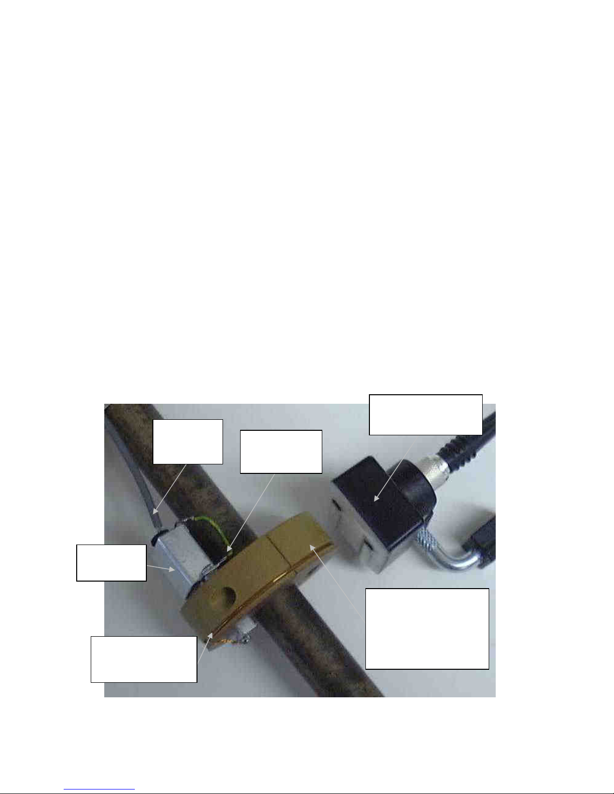
Figure 7 - Installation of Transmitter and Split-Ring "TX.MTGS" and Inductive Head IH2
INDUCTIVE HEAD IH2.
ALIGN PARALLEL TO
LOOP AS SHOWN.
AIRGAP 10
-
20MM
CABLING
FROM STRAINGAUGE
BRIDGE
0.7MM DIAMETER
COPPER WIRE LOOP.
DON’T OVERHEAT TABS
WHEN SOLDERING
GROUND CABLE
SCREEN &
TRANSMITTER P8
TO HOUSING
TRANSMITTER
SCREENING
COVER
TRANSMITTER ATTACHED
TO SHAFT WITH TX.MTGS
SPLIT-RING ASSEMBLY.
NOTE: COUNTER-BALANCE
MODULE (NOT SHOWN) WILL
NORMALLY FITTED AT 180°
TO TRANSMITTER
T
he following sections describe installation of each possible inductive power supply components combination:-head/loop,
loop/loop and loop/IP2 module). Installation procedure is the same for both single channel and multi-channel "D" range
PCM and also "B" range fm/fm systems.
MOST DIFFICULTIES WITH ROTARY TELEMETRY INSTALLATIONS OCCUR AS A RESULT OF DROPOUTS IN THE
INDUCTIVE POWER SUPPLY TO THE TRANSMITTER. PLEASE READ THE APPROPRIATE SECTION CAREFULLY!
5.1 INDUCTIVE HEAD IH2 OR IH2/L WITH SHAFT MOUNTED POWER PICKUP LOOP
The IH2 and long pole piece version IH2/L (for larger diameter shafts) consists of a coil wound around a "U" shaped ferrite
c
ore and encapsulated within a housing. The head is located in a position close to a loop antenna wound around the shaft.
An internal capacitor tunes the head inductance to resonance, necessary for efficient operation. In operation the IH2 coil is
energised by a power oscillator in the demodulator/decoder module, usually at 2MHz. This generates an alternating
magnetic field across the pole pieces, which induces power into the loop. The IH2 or IH2/L may be used with the special
manufacture split-ring assembly (general part number "TX.MTGS"), which will have either a locating groove for the loop
wire, an integrated glass-fibre ring with printed copper track, or a single/two turn loop wound onto the shaft itself (with an
intervening insulating layer of 10-15mm).
A fine tuning adjustment is incorporated in the IH2, IH2/L housing to enable initial tuning to resonance. If the installation is
close to metal components, which can affect the head tuning, this adjuster may be used to re-tune and improve efficiency.
Once set, the tuning core should be locked in position with a small amount of silicone rubber to prevent movement and a
possible loss of tuning (which would then cause a voltage drop in the DC supply to the transmitter).
5.1.1 Inductive Head IH2 or IH2/L with Power Pickup Loop in Split-Ring Assembly "TX.MTGS"
A system option for high RPM applications is the custom design split-ring assembly "TX.MTGS". This fits around the shaft
O
.D. and incorporates a power pickup/signal transmit loop antenna and also mounting for the transmitter, either in a cut-out
section or contained within the ring. The TX.MTGS ring is manufactured from phenolic composite or aluminium, dependant
upon the application.
See figure 7 below and "Suggested Installation Sequence" text.
Page 31

TM Page 31
5
.1.2 Suggested Installation for Inductive Head IH2-IH2/L with Power Pickup Loop in Split-Ring Assembly
a) Decide upon desired location for the strain gauges and split-ring assembly, preferably with a distance of 75mm or more
between the two. This is to prevent the inductive head magnetic field from inducing a voltage into the gauges or leadwires
and causing a "once per revolution" zero shift. The split-ring should also be positioned where any shaft displacement is at a
minimum, thus avoiding large variations in the air-gap between inductive head and the loop antenna on the split-ring
periphery. If the air-gap becomes too great a signal drop-out will occur. Finally, remember to leave space to mount the
inductive head - this location should be as far away as possible from metallic components or surfaces.
b) Install gauges, preferably using screened lead-out cabling.
Note: As the zero back-off at the analogue output of the telemetry system is limited to ±20% of the full scale measuring
range, it may be a good plan to incorporate trimming resistor pads into the strain gauge installation to facilitate balancing of
the bridge output to zero. This will not be necessary if strain levels are high (i.e. several mV output).
c) Calculate value for Rg (and Rcal if used) and install resistor onto transmitter.
d) If not pre-installed, fit transmitter and counter-balance module into the TX.MTGS split-ring assembly and install ring onto
the shaft. If the split-ring assembly does not have an integral loop antenna, wind a single turn of insulated copper wire
(0.7mm diameter is supplied ) into the peripheral groove on the TX.MTGS ring and solder connect to the transmitter loop
connection pins (do not overheat).
e) Connect strain gauge leadwires to transmitter, also the strain gauge leadwire screen to the transmitter housing - this
ensures single point grounding for the complete transmitter assembly. When connecting strain gauge signal leads check
polarity to ensure that output voltage will read correctly (positive torque=positive V out) and not backwards. Fit transmitter
screening cover.
f) Position the inductive head IH2 using the supplied universal mounting bracket, as shown in figure 4.1, keeping it well
clear of metal components or surfaces. Set the airgap to 10-20mm and connect the head to the demodulator/decoder
module or unit TNC socket "PICKUP", using the supplied cable. Note that if the inductive head is located too closely to a
metallic mass, losses or de-tuning may reduce the transmitter supply voltage to less than the minimum acceptable level of
5.8VDC. It may be possible to compensate for this using the IH2 tuning adjuster, otherwise the head position will have to
be altered. Remember to lock the core with silicone rubber after making any adjustments.
g) Carry out checkout as per section 4.3.
Page 32
TM Page 32
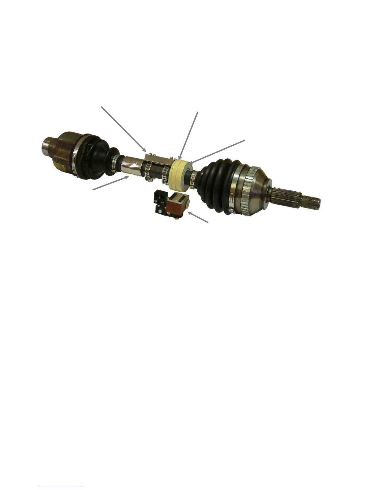
Figure 8 - Installation of Transmitter with Shaft mounted Loop & Inductive Head IH2
FIT CAK KIT STEEL STRAPPING
THROUGH SLOTS ON
UNDERSIDE OF TRANSMITTER.
JOIN ENDS WITH SUPPLIED
TENSIONERS. DO NOT OVER
TENSION
STRAIN GAUGE
INSTALLATION BENEATH
PROTECTIVE STAINLESS
STEEL SLEEVE
SINGLE TURN (2 TURNS FOR DIAMETER <60MM)
LOOP FROM SUPPLIED COPPER WIRE.
MINIMUM GAP AT ENDS. ENSURE AXIAL
ALGINMENT SO THAT WIRE REMAINS
BETWEEN IH2 POLE-PIECES DURING
ROTATION. TIE DOWN WIRE WITH 3 TURNS OF
POLYESTER TAPE
INDUCTIVE HEAD IH2
AERIAL LOOP SPACED
AWAY FROM SHAFT BY 3
TURNS (SEPARATE SINGLE
TURNS TO KEEP
THICKNESS CONSTANT) OF
20mm WIDE PVC FOAM
STRAIN GAUGE
INSTALLATION BENEATH
STAINLESS STEEL SLEEVE
5.1.3 Inductive Head IH2 or IH2/L with Power Pickup Loop Wound onto Shaft Using CAK Kit
In many applications, where shaft rotational speeds are not extreme and operating temperature below about +80°C, the
C
AK kit may be used to attach the transmitter to the shaft, using steel strapping. A separate loop antenna is wound around
the shaft to pickup power and transmit the data signal - required materials are included in the CAK kit.
Figure 8 shows a typical installation and the following text "Suggested Installation Sequence" details installation.
5.1.4 Suggested Installation Sequence for Inductive Head IH2 or IH2/L with Transmitter & Power Pickup
L
oop Using CAK Kit:
a) Decide upon desired location for the strain gauges and transmitter assembly, leaving space for the loop antenna - which
should be on the side of the transmitter away from the strain gauges. Locate the loop antenna where any shaft
displacement is at a minimum, thus avoiding large variations in the air-gap between inductive head and the loop. If the airgap becomes too great a signal drop-out will occur. Finally, space will be required to mount the inductive head - this
location should be as far away as possible from metallic components or surfaces.
b) Install gauges.
Note: As the zero back-off at the analogue output of the telemetry system is limited to ±20% of the full scale measuring
range, it may be a good plan to incorporate trimming resistor pads into the strain gauge installation to facilitate balancing of
the bridge output to zero. This will not be necessary if strain levels are high (i.e. several mV output).
c) Calculate value for Rg (and Rcal if used) and install resistor onto transmitter.
d) Attach transmitter to shaft using CAK banding and tensioners, then loop antenna using 3 insulating foam tape layers - as
detailed in figure 4.2., to space the loop away from the shaft. If the loop diameter is 60mm or less, wind 2 turns, which will
give improved power pickup. Solder connect loop ends to appropriate transmitter pins.
e) Connect strain gauge leadwires to transmitter, also screen to housing (if screened cable used). When connecting strain
gauge signal leads check polarity to ensure that output voltage will read correctly (positive torque=positive V out) and not
backwards. Fit transmitter screening cover.
f) Position the inductive head IH2 using the supplied universal mounting bracket, as shown in figure 4.2., keeping the head
clear of metal components or surfaces, otherwise losses may reduce the transmitter supply voltage to less than the
minimum acceptable level of 5.8VDC Set the air-gap to 15mm and connect the head to the demodulator/decoder using
supplied cable. If the head tuning adjuster is altered, remember to lock the core in position using silicone rubber after
making any adjustment.
g) Carry out checkout as per section 6
Page 33
TM Page 33
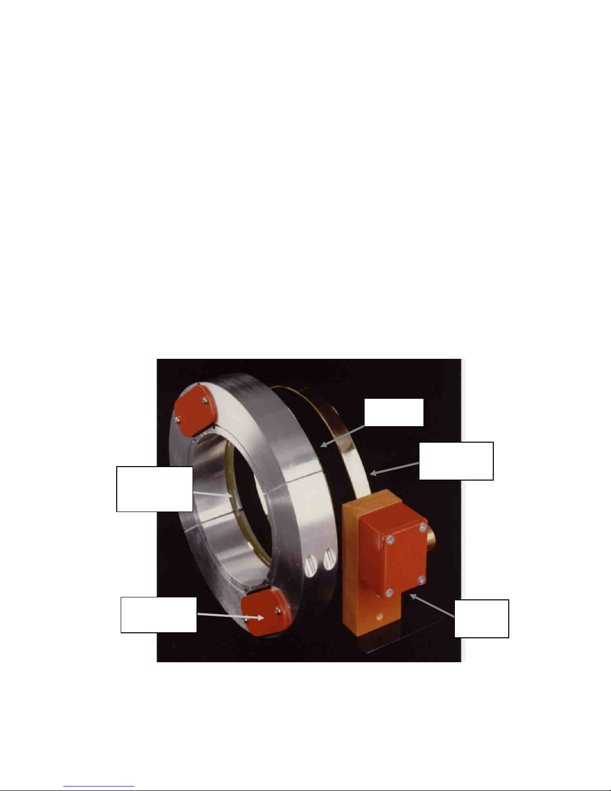
Figure 9 - Example of "TX.MTGS" Custom Split-Ring with IL2 Inductive Loop Assembly
CUSTOM
PACKAGED
IL2
LOOP ANTENNA
FORMED FROM
BRASS STRIP
ALUMINIUM
SPLIT-RING
TRANSMITTER
HOUSED WITHIN
RING
POWER PICKUP
LOOP ANTENNA
MOUNTED ON
SIDE OF RING
5.2 INDUCTIVE LOOP IL2 WITH SHAFT MOUNTED POWER PICKUP LOOP OR IP2 PICKUP
Although slightly more complex to install, the inductive loop arrangement can transmit higher power and will accommodate
m
uch greater shaft displacements in both radial and axial directions. Also, the actual loop interface transformer module
may be located remotely from the loop itself and connected by co-axial or flat ribbon cable. This can be very useful where
space is limited - inside gearboxes for example.
The IL2 module consists of a transformer to match the 50 ohms cable impedance to the loop antenna and a tuning adjuster
to enable loops of various sizes to be tuned to resonance. These parts are encapsulated within a phenolic-resin housing to
ensure maximum resistance to vibration. A range of different sized glass-fibre loop antennae are supplied as part of the IL2
parts set and loops may also be fabricated by the user (for example, oval shaped loop to accommodate large vertical shaft
displacements such as are found in vehicle driveline shafts). A mounting boss and universal mounting bracket provides a
means of installing and aligning the IL2 loop antenna. For demanding applications, the IL2 may be mounted using
bracketry and the body is drilled with 4 x m3 threaded holes to provide fixing points. Non metallic material must be used for
the bracketry.
In operation, the loop antenna is energised, via the interface transformer, by a power oscillator in the demodulator/decoder
module - usually at 2MHz frequency. This generates an alternating magnetic field within the loop antenna, which in turn
induces power into the power pickup loop. The IL2 loop antenna may also be used with custom designed split-ring shaft
mounting assemblies general part number "TX.MTGS", ( these incorporate either a locating groove for the loop wire or an
integrated glass-fibre ring with printed copper track) or a power pickup loop wound onto the shaft itself (with an intervening
insulating layer) using material provided in the CAK kit.
5.2.1 Inductive Loop IL2 with Power Pickup Loop in Split Ring Assembly "TX.MTGS"
Where a system is supplied with a custom design split-ring assembly it has been fully pre-tested and therefore requires little
a
djustment. The section below "Suggested Installation Sequence" details points to be remembered.
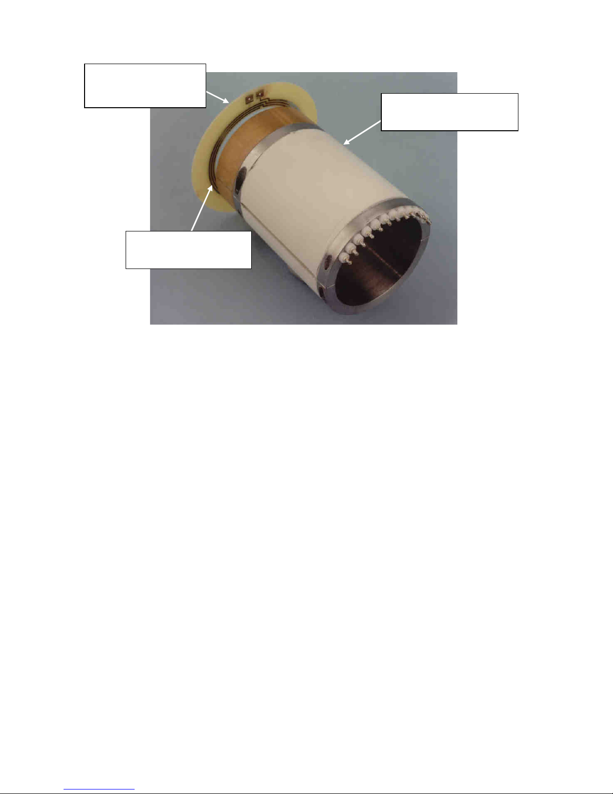
Figures 9, 10, and 11 show typical examples of custom designs.
Page 34
TM Page 34
Figure 10 - Example of Custom Transmitter for Gearbox Installation. IL2 Module Remotely Located &
Power Pickup Loop Integrated into Transmitter Housing
POWER PICKUP LOOP
ANTENNA HOUSED IN
PHENOLIC RESIN CARRIER
POWER TRANSMIT LOOP
ANTENNA. IL2 INTERFACE
MODULE IS REMOTELY
LOCATED
POWER PICKUP LOOP
ANTENNA HOUSED IN
PHENOLIC RESIN CARRIER
CUSTOM DESIGN 3 CHANNEL.
TRANSMITTER HOUSING 50MM
I.D. 62MM O.D.
5.2.2 Suggested Installation Sequence for Inductive Loop IL2 with Power Pickup Loop Integrated in SplitR
ing Assembly
a
) Decide upon desired location for the strain gauges and transmitter assembly, remembering that the transmitter
assembly should preferably be positioned at a distance of 75mm or more from the strain gauges in order to prevent the
inductive loop from inducing a voltage into the gauges or leadwires and causing a once per revolution zero shift. Also that
the power pickup loop antenna on the split-ring is best located where any shaft displacement is at a minimum, thus avoiding
large variations in the air-gap between power in inductive loop antenna and the TX.MTGS loop antenna. If the air-gap
becomes too great a signal drop-out will occur. Finally, space will be required to mount the inductive loop interface module
IL2 - this location should be as far away as possible from metallic components or surfaces.
b) Install gauges, preferably using screened lead-out cabling.
Note: As the zero back-off at the analogue output of the telemetry system is limited to ±20% of the full scale measuring
range, it may be a good plan to incorporate trimming resistor pads into the strain gauge installation to facilitate balancing of
the bridge output to zero. This will not be necessary if strain levels are high (i.e. several mV output).
c) Calculate value for Rg (and Rcal if used) and install resistor onto transmitter.
d) If not pre-installed, fit transmitter and counter-balance module into the TX.MTGS split-ring assembly and install ring onto
the shaft. If the split-ring assembly does not have an integral loop antenna, wind a single turn of insulated copper wire
(0.7mm diameter wire is supplied ) into the peripheral groove on the TX.MTGS ring and solder connect to the transmitter
loop connection pins (do not overheat).
e) Connect strain gauge leadwires to transmitter, also the strain gauge leadwire screen to the transmitter housing - this
ensures single point grounding for the complete transmitter assembly. When connecting strain gauge signal leads check
polarity to ensure that output voltage will read correctly (positive torque=positive V out) and not backwards. Fit transmitter
screening cover (wheref the transmitter has exposed connecting pins).
f) Position the inductive loop interface IL2 using the supplied universal mounting bracket, as shown in figures, keeping it
well clear of metal components or surfaces and axially aligned with the split-ring loop antenna. Connect the IL2 to the
demodulator/decoder module or unit TNC socket "PICKUP", using the supplied cable.
g) Carry out checkout as per section 4.3
Page 35
TM Page 35
INDUCTIVE
LOOP MODULE
IL2
INDUCTIVE
LOOP MODULE
IL2
IL2 MODULE
TUNING
ADJUSTMENT
PICKUP AERIAL LOOP
SPACED AWAY FROM
SHAFT WITH 3 LAYERS OF
INSULATING FOAM TAPE.
FOR LOOP DIAMETERS
<60MM USE 2 LOOP
TURNS TO INCREASE
POWER
TRANSMITTER
ATTACHED TO
SHAFT WITH
STEEL BANDING
STRAIN GAUGE
INSTALLATION
UNDERNEATH
PROTECTIVE
STAINLESS
STEEL SLEEVE
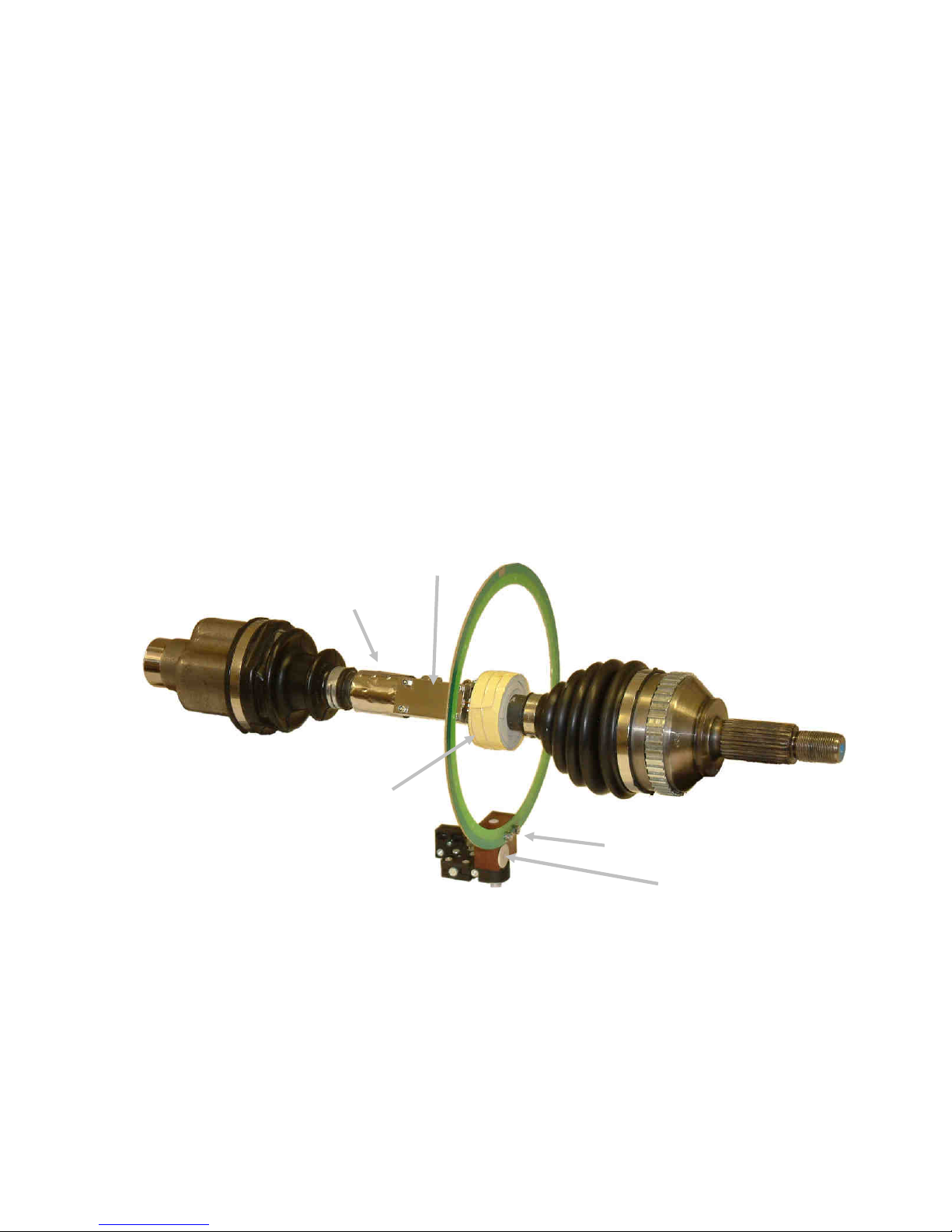
Figure 11 - Installation of Transmitter Using CAK Kit Parts & Standard IL2 Glass-Fibre Loop
IMPORTANT: A tuning adjuster is built into the IL2 module in order to be able to tune various different sizes of loop to
resonance. The adjusting core should be locked into position with a small amount of silicone rubber once the loop has
been tuned to give maximum voltage at the transmitter.
5.2.3 Inductive Loop IL2 with Power Pickup Loop Wound onto Shaft Using CAK Kit
In many applications, where shaft rotational speeds are not extreme and operating temperature below about +80°C, the
C
AK kit may be used to attach the transmitter to the shaft, using steel strapping and a separate loop antenna wound around
the shaft. Used in conjunction with the IL2 loop antenna, this combination allows considerable shaft displacement
combined with efficient power coupling. Figure 4.6 shows a typical installation using CAK materials and figure 4.7 an
installation using a custom loop , formed into an oval to increase allowable shaft displacement. The following text
"Suggested Installation Sequence" lists installation points.
Page 36
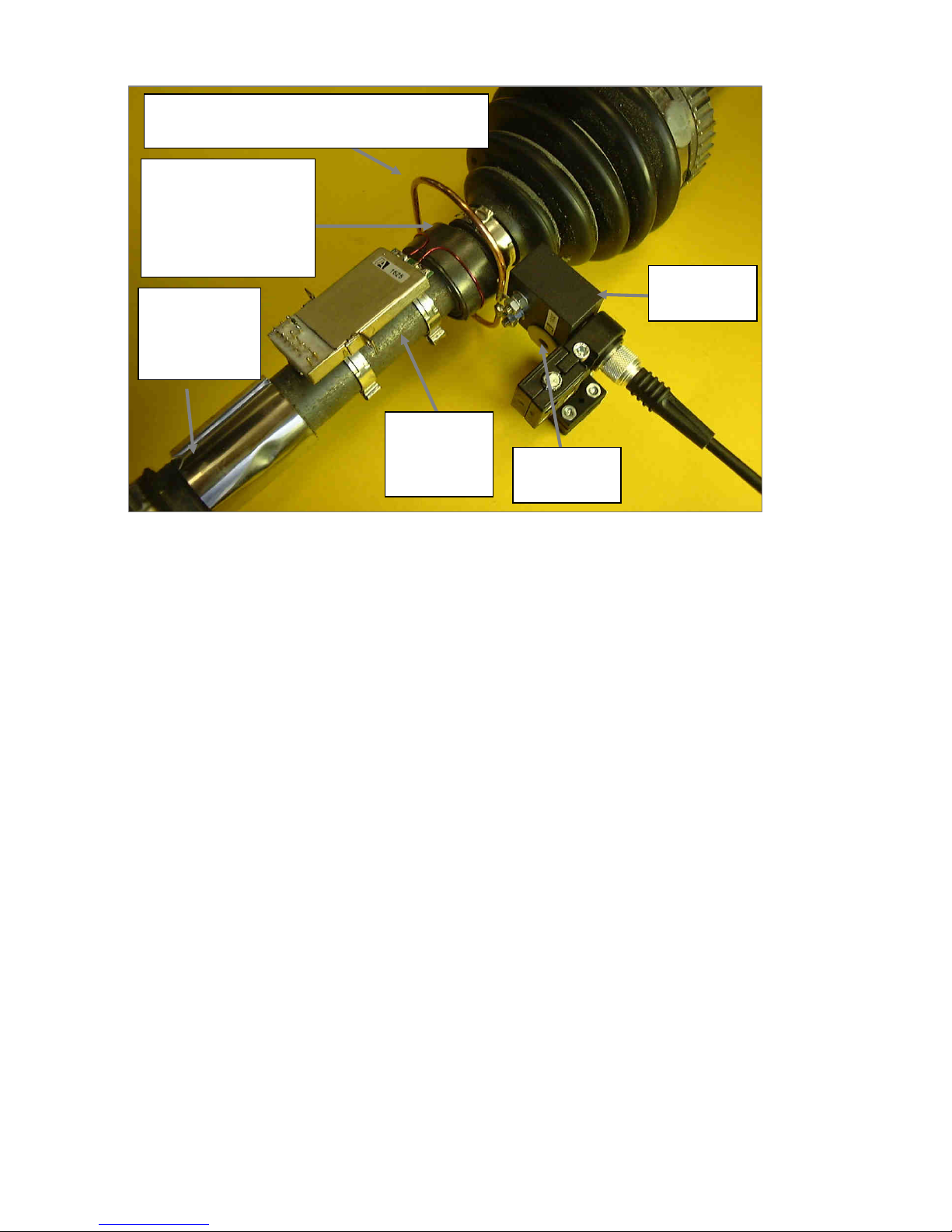
TM Page 36
Figure 12- Installation of Transmitter Using CAK Kit Parts & and IL2 with Custom Form Inductive Loop
STRAIN GAUGE
INSTALLATION
UNDERNEATH
PROTECTIVE
STAINLESS
STEEL SLEEVE
TRANSMITTER
ATTACHED TO
SHAFT WITH
STEEL
BANDING
PICKUP AERIAL LOOP
SPACED AWAY FROM
SHAFT WITH 3 LAYERS OF
INSULATING FOAM TAPE.
FOR LOOP DIAMETERS
<60MM USE 2 LOOP
TURNS TO INCREASE
POWER
INDUCTIVE POWER SUPPLY LOOP IN CUSTOM SHAPE.
FORMED FROM 3MM BRASS ROD & ATTACHED TO IL2
MODULE STUDS VIA M4 TAG WASHERS
IL2 MODULE
TUNING
ADJUSTMENT
INDUCTIVE
LOOP MODULE
IL2
5.2.4 Suggested Installation Sequence for Inductive Loop IL2 with Transmitter & Power Pickup Loop on
S
haft Using CAK Kit:
a) Decide upon desired location for the strain gauges and transmitter assembly, leaving space for the shaft mounted loop
antenna, which should be on the side of the transmitter opposite to the strain gauges. Locate the loop antenna where any
shaft displacement is at a minimum, thus avoiding large variations in the air-gap between the stationary loop and the shaft
mounted loop. If the air-gap becomes too great a signal drop-out will occur. Finally, space will be required to mount the
inductive head - this location should be as far away as possible from metallic components or surfaces.
b) Install gauges.
Note: As the zero back-off at the analogue output of the telemetry system is limited to ±20% of the full scale measuring
range, it may be a good plan to incorporate trimming resistor pads into the strain gauge installation to facilitate balancing of
the bridge output to zero. This will not be necessary if strain levels are high (i.e. several mV output).
c) Calculate value for Rg (and Rcal if used) and install resistor onto transmitter.
d) Attach transmitter to shaft using a band of CAK strapping through each slot and tensioners, then 3 insulating foam tape
layers and polyester tape - as detailed in figure 4.2., to space the loop away from the shaft. Then wind on 1 turn insulated
wire to form power pickup loop. If the loop diameter is 60mm or less, 2 turns will give improved power pickup. Solder
connect loop ends to appropriate transmitter pins.
e) Connect strain gauge leadwires to transmitter, also the strain gauge leadwire screen (if screened cable is being used) to
the transmitter housing - this ensures single point grounding for the complete transmitter assembly. When connecting
strain gauge signal leads check polarity to ensure that output voltage will read correctly (positive torque=positive V out) and
not backwards. Fit transmitter screening cover.
f) Fit a suitable diameter of loop to the IL2 and position it, using the supplied universal mounting bracket, as shown in figure
4.6., ensuring that the loop is well clear of metal components or surfaces. If access to the shaft end is not available, the
loop may be positioned around the shaft before attaching it to the IL2 interface module. Connect the head to the
demodulator/decoder module or unit TNC socket "PICKUP", using the supplied cable.
g) Carry out checkout as per section 6
Page 37
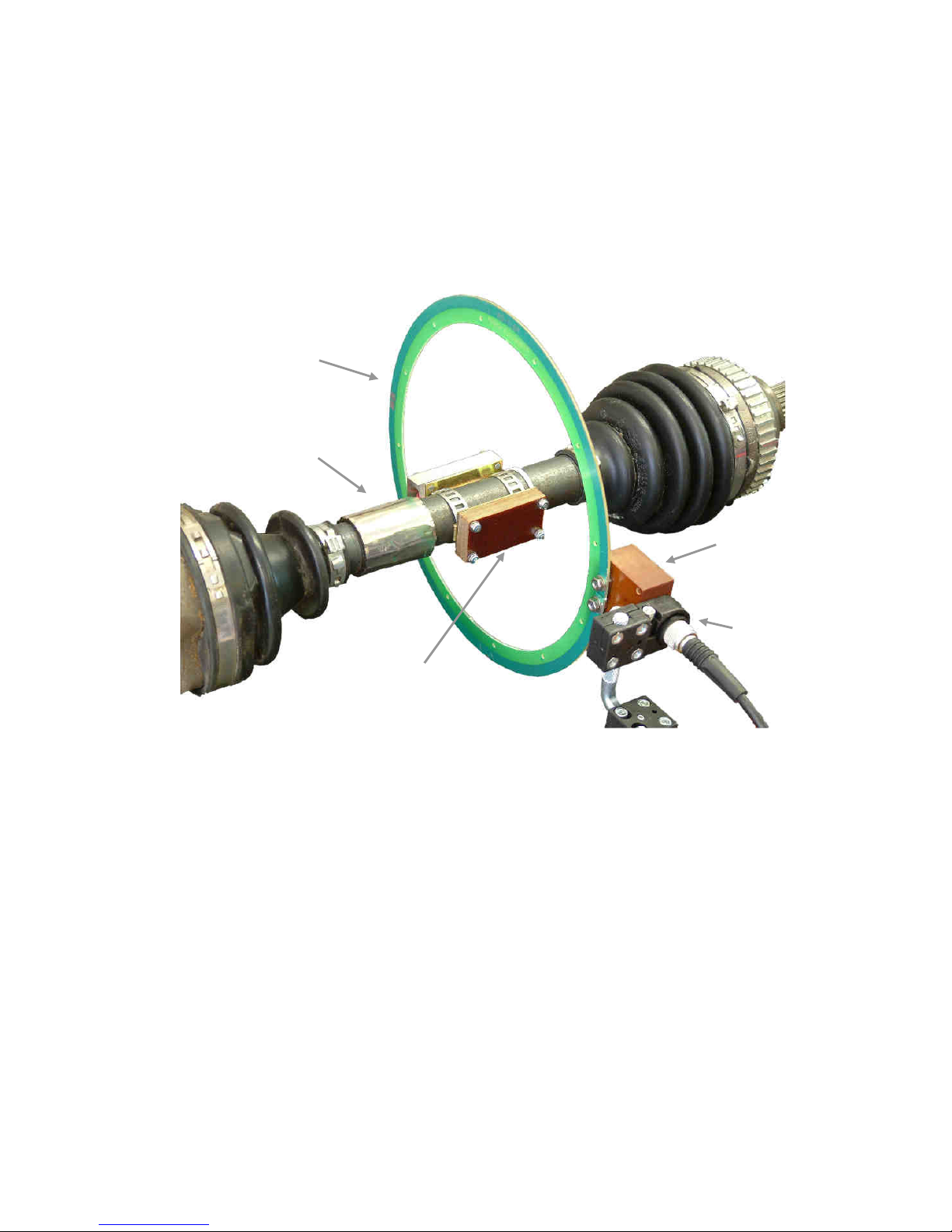
TM Page 37
TRANSMITTER & IP2
PICKUP ATTACHED TO
SHAFT WITH CAK KIT
STEEL STRAPPING
STRAIN GAUGES
UNDER STAINLESS
STEEL SLEEVE
STANDARD IL2
GLASS-FIBRE
LOOP
UNIVERSAL
MOUNTING
BRACKET
IL2 INTERFACE
MODULE
Figure 13 - Shaft Mounted Transmitter & IP2 Inductive Pickup Module with Standard IL2 Loop
5.2.5 Inductive Loop IL2 with Inductive Power Pickup IP2 on Shaft Using CAK Kit
Instead of a shaft-mounted loop antenna, this arrangement uses a shaft mounted pickup module IP2 to collect power. This
i
s the best configuration where maximum air-gap and tolerance of shaft displacement is required. However, because the
magnetic coupling across large air-gaps is small, high resistance strain gauges of 1000 or 2000 ohms should be used - not
500 or 350 ohms. The IP2 module is a very convenient solution in many applications, as it is pre-tuned for optimum power,
is easily installed together with the transmitter using the same steel banding loops and requires minimal axial shaft length.
Figures 4.8 and 4.9 illustrate typical installations. Figure 4.10 is an example of what is probably the maximum achievable
air-gap (±200mm and ±60mm ). Note that the presence of metal close to the loop antenna will reduce the useable air-gap.
Page 38
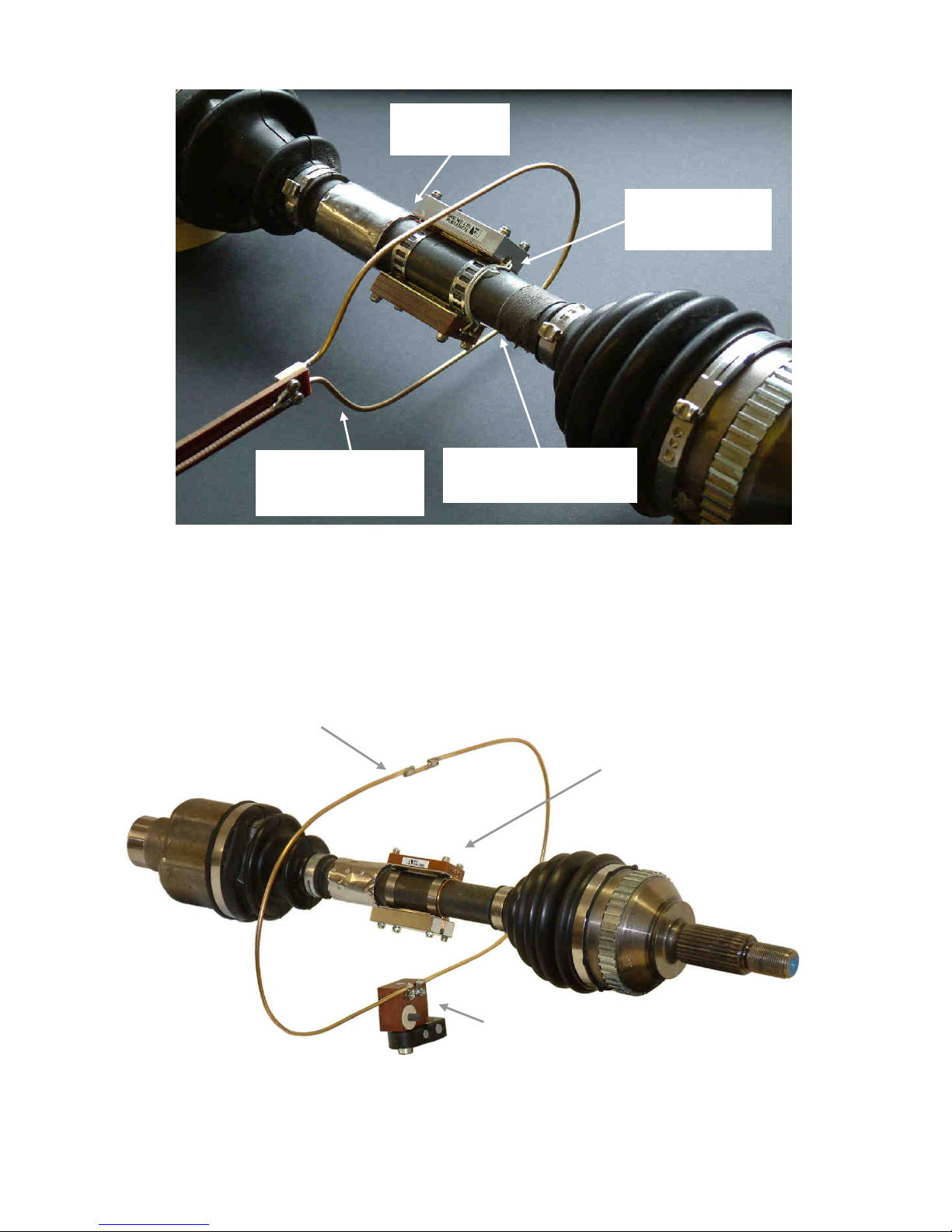
TM Page 38
STRAIN GAUGES
UNDER STAINLESS
STEEL SLEEVE
CONNECT IP2 MODULE TO
TRANSMITTER LOOP ANTENNA
PINS
CUSTOM FORM LOOP
ANTENNA WITH REMOTE
CONNECTION TO IL2
INTERFACE MODULE
TRANSMITTER & IP2
PICKUP ATTACHED TO
SHAFT WITH CAK KIT
STEEL STRAPPING
Figure 14 - Shaft Mounted Transmitter & IP2 Inductive Power Pickup Module with Custom Form Loop
EXPERIMENTAL CUSTOM FORM LOOP
ANTENNA (540mm x 180mm)
FABRICATED FROM 2.5mm BRASS ROD. IN A
PRACTICAL DESIGN 5mm ROD WOULD BE
REQUIRED TOGETHER WITH NON-METALLIC
SUPPORT BRACKETRY
Figure 15 - Example of Custom Form Loop Antenna (440mm x 180mm)
TRANSITTER & IP2 PICKUP
MOUNTED ON SHAFT USING
CAK KIT STEEL STRAPPING
IL2 INTERFACE
MODULE
I
Page 39

TM Page 39
5.2.6 Suggested Installation Sequence for Inductive Loop IL2 with Transmitter & IP2 Power Pickup on
S
haft Using CAK Kit:
a) Decide upon desired location for the strain gauges and transmitter/IP2 Pickup assembly. If possible, locate the
transmitter assembly where any shaft displacement is at a minimum, thus avoiding large variations in the air-gap between
the stationary IL2 loop antenna and the shaft mounted IP2 pickup. If the air-gap becomes too great a signal drop-out will
occur. Finally, keep the IL2 loop antenna location as far away as possible from metallic components or surfaces.
b) Install gauges.
Note: As the zero back-off at the analogue output of the telemetry system is limited to ±20% of the full scale measuring
range, it may be a good plan to incorporate trimming resistor pads into the strain gauge installation to facilitate balancing of
the bridge output to zero. This will not be necessary if strain levels are high (i.e. several mV output).
c) Calculate value for Rg (and Rcal if used) and install resistor onto transmitter.
d) Attach transmitter and IP2 module to shaft using a band of CAK strapping plus tensioner through each slot.
e) Connect strain gauge leadwires to transmitter, also the strain gauge leadwire screen (if screened cable is being used) to
the transmitter housing - this ensures single point grounding for the complete transmitter assembly. When connecting
strain gauge signal leads check polarity to ensure that output voltage will read correctly (positive torque=positive V out) and
not backwards. Connect IP2 to transmitter loop input pins and fit transmitter screening cover.
f) Fit a suitable diameter of loop to the IL2 and position it, using the supplied universal mounting bracket, as shown in figure
4.8., ensuring that the loop is well clear of metal components or surfaces. If access to the shaft end is not available, the
loop may be positioned around the shaft before attaching it to the IL2 interface module. In the case of custom shape loops,
loop ends may be soldered to M4 tag washers, which are then connected to the IL2 module studs. More substantial loop
material and fixings may be used where vibration level require - the loop material is not critical provided that it has a low
electrical resistance (brass, copper aluminium) and makes good, low-resistance contact with the IL2 studs.
g) Connect head to the demodulator/decoder module or unit TNC socket "PICKUP", using the supplied cable.
h) Carry out checkout as per section 6
6 SYSTEM CHECKOUT
This may be carried out as a benchtop checkout or after installation onto the component under test.
a
) Apply power to the demodulator/decoder module/caseframe. The red LED should light, indicating power supply present,
also the green LED indicating good data (on the "B" range systems the green LED indicates adequate R.F.signal strength).
If the IL2 inductive loop form of power is being used, it will be necessary to tune the loop (using the adjuster on the IL2
module), otherwise the transmitted power in unlikely to be sufficient. When power is sufficient the green LED will turn on.
b) Monitor the DC power at the "TX V" socket on the demodulator/decoder. A minimum of 6V is necessary, preferably 78V. Adjust the IH2 or IL2 to obtain maximum volts. Note that this monitor facility is not available on "B" range systems,
which are single channel, and the supply voltage will have to be monitored at the transmitter itself.
c) If possible, rotate shaft or displace the inductive head/loop relative to shaft to simulate operating conditions and ensure
that the transmitter supply remains above 6VDC, preferably 7-8V (i.e. no dropouts occur due to variable air-gap).
d) Monitor analogue output voltage and adjust to zero if necessary. Check noise level, which should not exceed 10mV
RMS., typically <3mV RMS.
e) Monitor analogue output at demodulator/decoder. If possible, apply a calibration signal to the strain gauge bridge and
check for correct scaling.
Page 40

TM Page 40
6.1 NON-OPERATION
I
f the system does not function the problem is almost certainly due to insufficient supply voltage to the transmitter, caused
by over large air-gap, proximity of metal close to one or both loops, or a seriously de-tuned condition. A simple way to
check is to apply a 6-9VDC supply (battery, for example) to the transmitter DC power supply pins (not the bridge excitation
pins). If the system then works, the problem is confirmed as being insufficient volts from the inductive power supply
Voltages across the power in and power pickup loops may be checked with an oscilloscope (high impedance probe):
1) Across smallest (65mm diameter) IL2 loop when correctly tuned: 12V P/P
2) Across largest IL2 loop when correctly tuned: 70V P/P
3) Across shaft mounted power pickup loop: 2-3V P/P
4) Across IP2 module output: 4V P/P
If voltages are less than the above either loop efficiency is being affected by the proximity of metal or the pickup loop
requires partial tuning - see section 4.5 below.
6.2 IMPROVING EFFICIENCY OF INDUCTIVE POWER SUPPLY
Apart from the air-gap being too large, there are 4 main reasons for inefficiency in the inductive power supply:
1
) Self-inductance in the power pickup loop, which limits power supplied to the transmitter rectifier circuitry. Inductance is
directly proportional to loop diameter and the problem becomes more serious for loop diameters greater than about 150mm.
2) Poor flux linkages between power transmitting and power pickup components, particularly a problem in the case of the
inductive head when used with small loop diameters. The loop form of power input is much more efficient in this respect.
3) Poor quality factor "Q" of the loop due to insufficient insulation from the shaft and/or the proximity of metal components.
This causes a dissipation of electrical energy, reducing that available to the transmitter.
4) De-tuning of the inductive head caused by close proximity to metal. This reduces head efficiency.
Assuming that no improvements can be made by reducing air-gap, re-locating any from metal components or improving the
power in head/loop tuning, there several methods of improving performance:
1) Incorporate a capacitor in series with the power pickup loop to partially cancel out the loop self-inductance. The
transmitter input circuitry is optimised for a loop diameter of 90mm, but for larger loop diameters, the required capacitor
value (within approximately ±10%) may be calculated from:
C (in Pfd) = 29 x 10
5
Loop Diameter in mm - 90
T
o obtain the greatest possible improvement, the exact capacitor value may have to be determined experimentall. It is
important that the capacitor be a high quality type (COG, NPO or silvered-mica dielectric), suitable for RF operation.
Tantalum or electrolytic capacitors, for example, are quite unsuitable. The output power improvement can be in the order
50-200%, dependant somewhat upon loop diameter (for large loop diameters, the improvement is not as great, since stray
capacitance effects tend to swamp the tuning capacitance).
For loop diameters less than about 60mm, increase the number of turns to two, three for less than 30mm diameter.
This may give sufficient improvement, if not a series tunig capacitor may be added. Calculate the value from:
C (in Pfd) = 29 x 10
5
(Loop Diameter in mm x n2 ) - 90
n = number of turns
Increasing the power pickup loop turns increases the flux linkages mentioned in (2), but, by spreading the turns slightly,
a
lso has the advantage of improving power pickup when the shaft moves in the axial direction - due to vehicle suspension
movement, for example. Spacing between the turns may be increased to about 4mm.
2) Insert a band of "Mu-Metal" (high permeability nickel alloy) underneath the power pickup. Firstly insulate the shaft
surface using 0.5mm thick glass-fibre tape and then wind 1 turn of 0.1- 0.2mm thickness x 40mm wide Mu-Metal on top of
the glass-fibre. The ends of the Mu-Metal band must stop approximately 2mm before making contact with each other. The
metal then acts as a form of armature and concentrates the magnetic field into the loop. The recommended method of
supporting the metal band and loop on the shaft surface is to use a bandage of glass-fibre tape, impregnated with epoxy
Page 41

TM Page 41
resin. . This arrangement is useful where space is very limited or rotational speed is exceptionally high and the power
p
ickup loop antenna needs to be installed directly on the shaft surface. Without the presence of the Mu-Metal, magnetic
field would be dissipated in the shaft metal. Materials are available from Astech Electronics.
3) Where a substantial air-gap of up to 50mm or more is required to accommodate shaft displacements, the power pickup
loop may be overwound with a second winding, tuned to 2MHz. This will increase flux linkages and considerably improve
useable air-gap and power pickup. Winding details will depend upon the diameter, but a typical figure would be 10-15 turns
of 0.5mm diameter wire and a capacitor in the range 1000-2000Pfd. Optimum values depends upon several factors
including shaft diameter, air-gap and transmitter type. Contact Astech for application information.
6.3 ATTACHING TRANSMITTER/IP2 PICKUP MODULE ON SMALL DIAMETERS
T
he steel strapping supplied in the CAK kit has a limitation of about 35mm installation diameter, making it difficult to apply
to small shafts. For this type of application a special version of the TX31D baseplate is available from Astech, which has
tabs at each end of the plate. After locating the baseplate, (to which the transmitter has been attached), on the shaft, the
tabs are overwound with 12mm wide x 0.18mm thickness high-strength self-adhesive glass-fibre tape. Two turns should be
applied, followed by two further turns interleaved with epoxy-resin adhesive to ensure integrity of the "bandage". Assuming
that high strength (240N/cm) tape is used and the epoxy is correctly cured, tensile strength of the "bandage will be
approximately 90kg.
For comparison, the total load on the loops in the case of a TX31D transmitter and 25mm diameter shaft is as follow:
1,000 RPM = 1.25kg
2,000 RPM = 5kg
3,000 RPM = 11.25kg
4,000 RPM = 20kg
Page 42
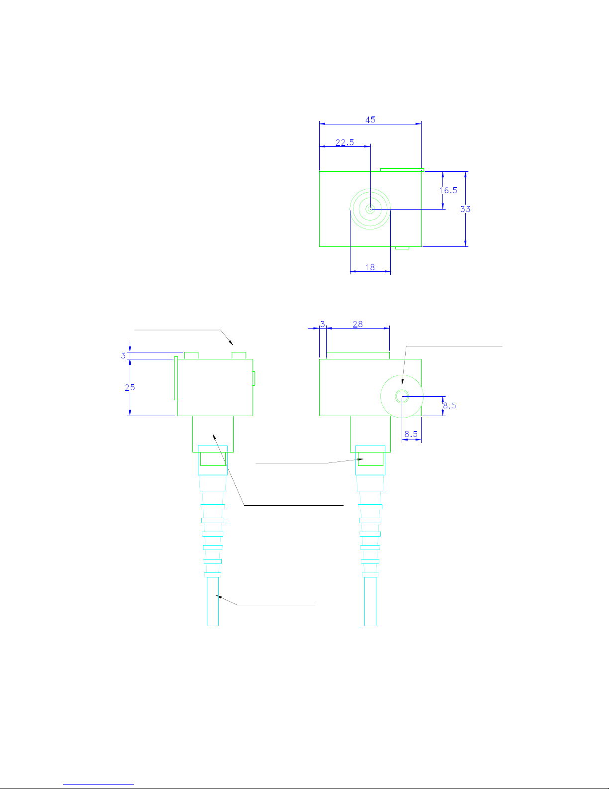
TM Page 42
FERRITE TUNING SLUG
TNC CONNECTOR
Material: Body, Carp grade Tufnol
Mounting Boss: 18mm Diameter
Connector: TNC Socket (Female)
Tolerance: ±0.1mm
RG58 TYPE CABLE
MOUNTING BOSS
FOR UNIVERSAL CLAMP
2 x Ferrite Pole Pieces
6.4 DIMENSIONED DRAWINGS OF IH2 & IL2
Figure 16 - Dimensioned Drawing of Inductive Head IH2
Page 43
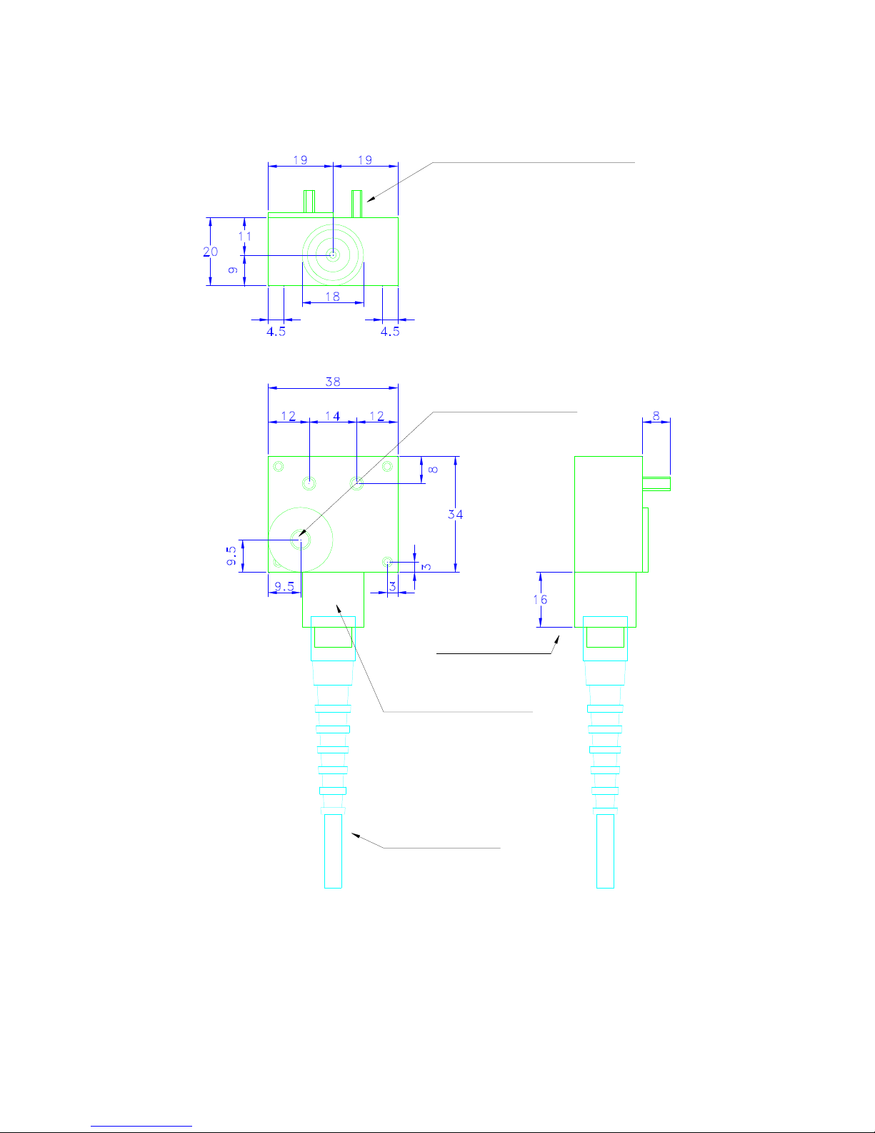
TM Page 43
Material: Body, Carp grade Tufnol
Studs: 2 x M4
Body Mounting Holes: 4 x M3 Threaded.
(Alternative to Boss) Note: Attach only
to non metalic backet)
Connector: TNC Socket (Female)
Tolerance: ±0.1mm
M4 STUDS FOR LOOP MOUNTING
TNC CONNECTOR
RG58 TYPE CABLE
MOUNTING BOSS
FOR UNIVERSAL CLAMP
FERRITE TUNING SLUG
Figure 17 - Dimensioned Drawing of Inductive Loop Interface Module IL2
 Loading...