

Page 1
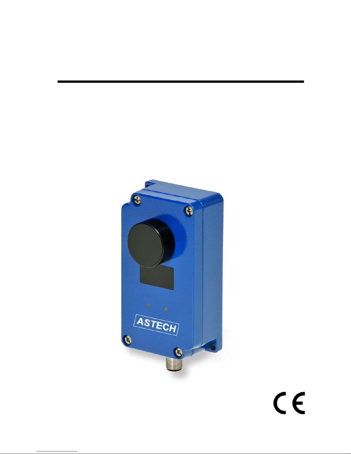
Manual
LDS10A
Version 1.0
Page 2

LDS10A Manual
Page 2 ASTECH GmbH
Dear User,
You are advised to carefully read this User Manual before powering on the
LDS10A LED distance sensor for the first time.
This is necessary to ensure that you will be able to utilize all the capabilities
and features which your new acquisition provides.
This technology is subject to continuously ongoing development.
Editorial deadline: May 2018
Firmware version: ≥ 1.0
Manual version: V 1.1
File: Manual_LDS10A_EN_V1.1.docx
Note:
Proper care has been used in compiling this document. No liability will be
accepted in the event of damage resulting from failure to comply with the
information contained herein.
Revisions history
Manual Version
Date
Changes
1.0
01.02.2018
First release
1.1
01.05.2018
First update
ASTECH GmbH, Schonenfahrerstr. 5, 18057 Rostock, Germany
Internet www.astech.de E-Mail [email protected]
Phone +49 (0)381 / 44073-0 Fax +49 (0)381 / 44073-20
Page 3

LDS10A Manual Content
ASTECH GmbH Page 3
I. Content
1 General ............................................................................................ 7
2 Safety Instructions ........................................................................... 7
2.1 General Safety Instructions ..................................................... 7
2.2 Intended & Conforming Use .................................................... 7
2.3 Nonconforming use ................................................................. 8
2.4 LED Classification ..................................................................... 9
2.5 Electric Supply ......................................................................... 9
2.6 Important Operating Advice .................................................... 9
3 Technical Data ............................................................................... 10
4 Mechanical Mounting Conditions ................................................. 11
5 Electrical Connection ..................................................................... 12
5.1 Connector Terminal ............................................................... 12
5.2 RS485 connection .................................................................. 14
5.3 Analog current output ........................................................... 14
5.4 Digital switching outputs Q1 and Q2 ..................................... 16
5.5 Device LEDs ............................................................................ 17
6 Start-up and measurement principle ............................................ 19
6.1 Start up .................................................................................. 19
6.2 Measurement principle ......................................................... 20
6.3 Measurement rate ................................................................. 22
7 MODBUS-Parameter ...................................................................... 24
7.1 General .................................................................................. 24
7.2 Read-only parameters ........................................................... 24
7.3 Write-only parameters .......................................................... 25
Page 4

Content LDS10A Manual
Page 4 ASTECH GmbH
7.4 Read/Write parameters ......................................................... 27
7.5 MODBUS RTU – Register addressing ..................................... 32
8 Part Numbers ................................................................................. 34
9 EG Declaration of Conformity ........................................................ 35
Page 5

LDS10A Manual Content
ASTECH GmbH Page 5
II. List of Figures
Figure 1 : Dimensional drawing ............................................................. 11
Figure 2 : LDS10A connector pin assignments ...................................... 12
Figure 3 : Wiring diagram of analog output .......................................... 14
Figure 4 : Output current and parameter of QA ................................... 15
Figure 5 : Digital switching output ......................................................... 16
Figure 6 : Device LEDs ............................................................................ 17
Figure 7 : Program ProsoftP1 ................................................................ 19
Figure 8 : Example for parameter OFFSET ............................................. 29
Page 6

Content LDS10A Manual
Page 6 ASTECH GmbH
III. List of Tables
Table 1 : Technical Data ......................................................................... 10
Table 2 : Pin assignment connector and interface cable ....................... 13
Table 3 : Meaning of Status-LED signals ................................................ 18
Table 4 : Meaning of Output-LED signals .............................................. 18
Table 5 : Examples for resulting measurement rate ............................. 23
Table 6 : Status byte information .......................................................... 25
Table 7 : Factory settings of the LDS10A ............................................... 25
Table 8 : Teach byte description ............................................................ 26
Table 9 : List of Modbus register addresses .......................................... 32
Table 10 : Part Numbers ........................................................................ 34
Page 7

LDS10A Manual General
ASTECH GmbH Page 7
1 General
The LDS10A is an industrial grade distance sensor using advanced
measurement and detection capabilities based on patented signal processing
algorithms. It provides different interfaces to transmit the detection results to
post processing unit like PLCs in industrial applications.
The implemented sensing technology is based on infrared LED illumination
and the time-of-flight of light principle. The LED emitters illuminate the area of
interest (pulsed at high frequency) and the single channel sensor receiver
collects the backscatter of the emitted light and measures the time taken for
the emitted light to return back to the sensor. A single photodetector is used
and provides a full-beam sensing module. Oversampling and accumulation
techniques are used to provide extended resolution and range.
2 Safety Instructions
2.1 General Safety Instructions
These safety and operating instructions should be carefully read and followed
during practical work with the LDS10A.
There is danger of electrical shock. For necessary repair work, the
LDS10A may not be opened by anyone other than authorized
personnel. Unauthorized intervention into the inner product space
will void any warranty claims.
Compliance with all specified operating conditions is necessary.
Failure to observe advisory notes or nonconforming product usage may cause
physical injury to the user or material damage to the LDA10A.
Cable connectors must not be plugged or unplugged under voltage.
Remember to turn voltage supply off before you begin working on cable
connections.
2.2 Intended & Conforming Use
Measurement of distances
Special measuring functions
Page 8

Safety Instructions LDS10A Manual
Page 8 ASTECH GmbH
Compliance with prescribed temperatures for operation/storage
Operation at correct voltage level
Application of specified signal levels to the appropriate data lines
2.3 Nonconforming use
Do not operate the LDS10A in any other way than described under
"Intended & Conforming Use" above and only in a proper working
condition
Safety devices must not be defeated or otherwise rendered
ineffective
Information and warning signs must not be removed
Repair work on the LDS10A must not be carried out by anyone
other than authorized personnel.
Avoid using the LDS10A without certified protection in an explosive
environment
Measurement with the LDS10A pointed at the sun or other strong
light sources may produce faulty results
Measurement of targets with poor surface reflectance in a strongly
reflecting environment may also result faulty measurements.
Measurement of strongly reflecting surfaces may deliver faulty
results.
Measurement performed through transparent optical media, for
example glass, optical filters, Plexiglas, etc. may equally produce
incorrect results.
Measurement on translucent objects (materials allow light to pass
through, but are not transparency, e.g. polystyrene, wax, different
plastics etc.) can give a too large measured value, since also light is
reflected by deeper layers
Rapidly changing measuring conditions are likely to falsify the result
of measurement
Page 9

LDS10A Manual Safety Instructions
ASTECH GmbH Page 9
2.4 LED Classification
The LDS10A meets the requirements of the “Exempt lamp class” of IEC
62471:2006.
The sensor can be used without any additional safety protection.
2.5 Electric Supply
Use only 10 V to 30 V (direct voltage) for LDS10A operation. Use only the
specially designated connector terminal for voltage supply.
Specified signal levels must not be exceeded, in order to guarantee correct
data communication.
2.6 Important Operating Advice
To make full use of the systems inherent performance capabilities and achieve
a long service life, you should always follow these operating rules:
Do not touch any of the module's parts with bare hands.
Proceed with care when removing dust or contamination from
optical surfaces!
Prevent shock impacts during transport and use of the LDS10A
Prevent the LDS10A from overheating.
Prevent the LDS10A from major temperature variances during
operation
In accordance with IP67 internal protection standards, the LDS10A
is designed to be splash proof and dustproof.
Read these safety and operating instructions with care and follow
them in practical use.
Page 10

Technical Data LDS10A Manual
Page 10 ASTECH GmbH
3 Technical Data
Table 1 : Technical Data
Sensing range
1)
Onto natural target (20 %)
Onto target board (90%)
0.1 m … 10 m
0.1 m … 40 m
Accuracy
2)
50 mm
Repeatability
± 5 mm
Resolution
1 mm
Measuring frequency
2.2 Hz … 140 Hz
Lighting
Infrared-LED, 850 nm
Lighting classification
Exempt class IEC 62471:2006
Lighting beam divergence
3°
Receiver beam divergence
6°
Operating temperature
-25 °C up to +75 °C
Supply voltage
10 V … 30 V DC (protected against polarity
reversal)
Power consumption
< 3 W
Serial data interface
RS485, MODBUS RTU, 19.400 Baud
Digital output
2x PNP, NO/NC selectable
Analogue output
0/4 mA ... 20 mA current output,
Adjustable range limits, 10 bit
Load impedance of analogue
Output
< 500 Ω at VCC = 24V, < 150 Ω at VCC = 12 V
Status indicator
2x RGB-LED on top cover
Connector
8 pin, M12-standard, male
Housing material
Aluminum, powder coated
Dimensions (L x W x H)
131 mm x 64 mm x 50 mm, incl. connector
Weight
280 g
Mounting
2 holes for M4 screws, 105 mm x 56 mm
Protection class
IP 67 (waterproof and dust protected)
EMC
IEC 61326-1
1)
Dependent on target reflectance, surface structure, ambient light and atmospheric conditions
2)
Single measurement, statistical spread 95 %
Page 11
LDS10A Manual Mechanical Mounting Conditions
ASTECH GmbH Page 11
4 Mechanical Mounting Conditions
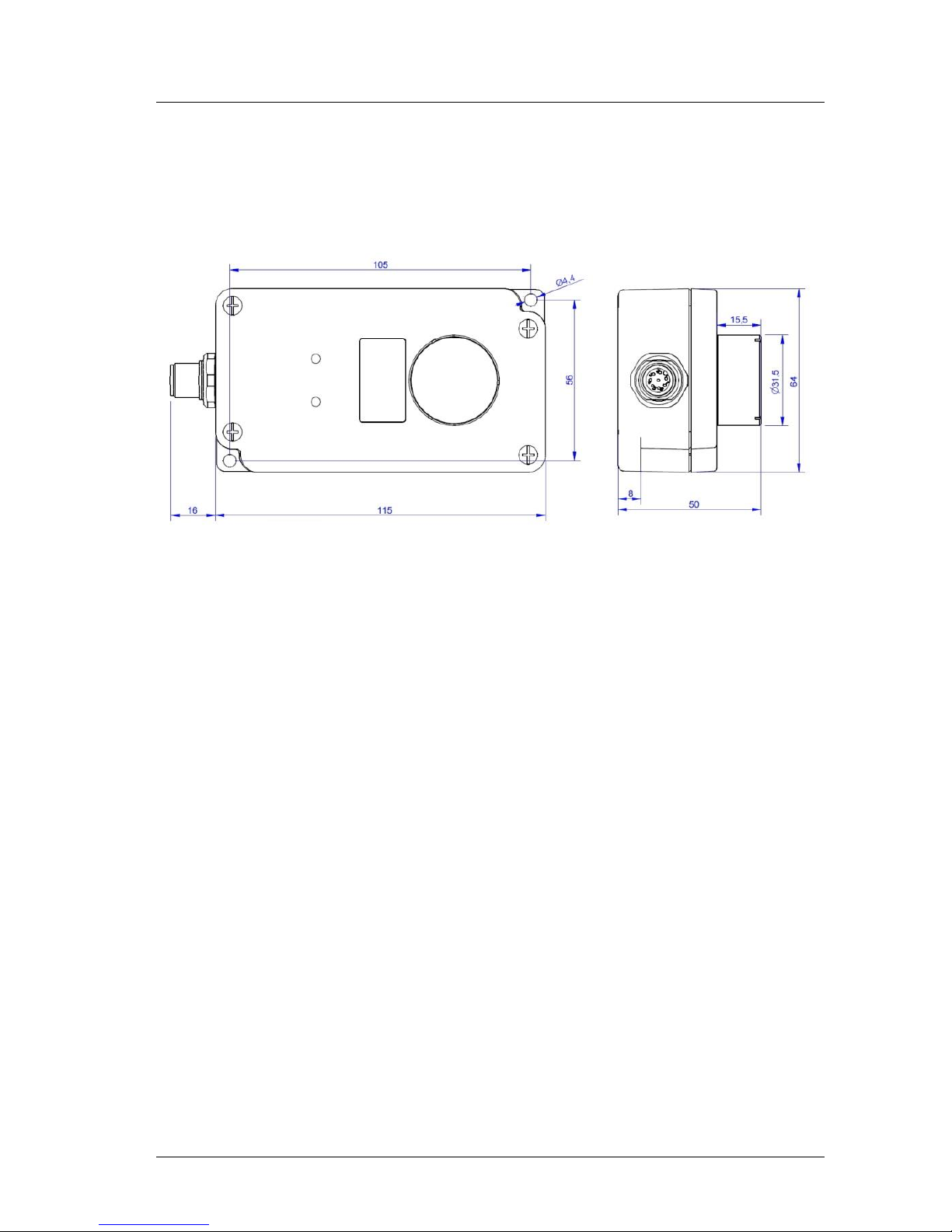
The casing consists of rugged, corrosion-resistant, casted aluminum with
powder coating. It provides 2 through holes for base plate mounting.
Figure 1 : Dimensional drawing
The zero-point has been introduced for constructional design reasons. It is
located appr. 8 mm above the bottom of the housing and can be compensated
with the help of parameter “Offset“.
Page 12
Electrical Connection LDS10A Manual
Page 12 ASTECH GmbH
5 Electrical Connection
5.1 Connector Terminal
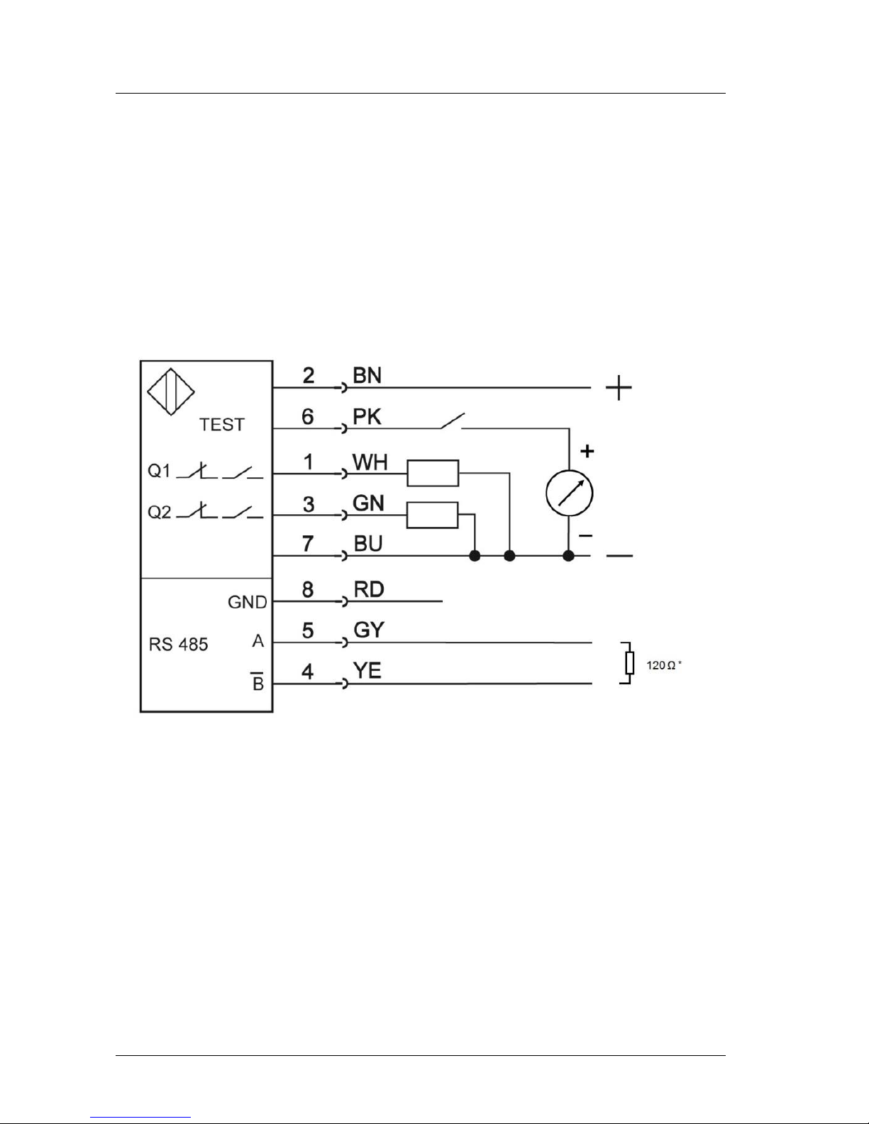
The male connector flange is made in compliance with industry M12-standard
with 8 pins. This connector type guarantees optimized screening and a high IP
degree. The connection provides IP67 protection in connected state.
Compatible cable jacks and interface cables with different length are available
(standard 5 m).
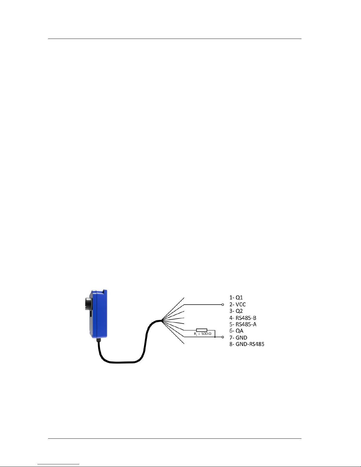
Figure 2 : LDS10A connector pin assignments
Page 13
LDS10A Manual Electrical Connection
ASTECH GmbH Page 13
Table 2 : Pin assignment connector and interface cable
Pin
Color
Assignment
Function
1
White
Q1
Digital output 1
2
Brown
VCC
Power supply
3
Green
Q2
Digital output 2
4
Yellow
RS485-B
RS485 line B, inverted
5
Grey
RS485-A
RS485 line A, not inverted
6
Pink
QA
Analogue output 4-20 mA
7
Blue
GND
Ground (power supply)
8
Red
GND-RS485
Ground (RS485, internally
connected to GND)
GND wires are connected to an internal collective ground point. They provide
the reference potential for all voltage values quoted below.
Caution: If input signals are applied to an output port, this may
damage the LDS10A!
Do not connect the current output QA to the power supply. This will
destroy the interface board!
All outputs are protected against steady short-circuit currents.
Caution: The cable end is exposed! The user is responsible to take
precautions that will prevent any kind of shorts! The cable shield has
to be connecting to earth with low resistance.
Page 14
Electrical Connection LDS10A Manual
Page 14 ASTECH GmbH
5.2 RS485 connection
The serial data interface of the LDS10A works according to the RS485-standard
(EIA-485) with two data lines with inverse polarity. It provides fieldbus
capabilities with multiple access and device identification by address.
The used protocol is Modbus RTU with binary data transmission. The
communication setup is as follows:
Baudrate: 19.200 baud
Parity: even
Start/Stop bits: 1 Stop Bit
The signal lines of the RS485 interface should not be left open. If not in use it
is recommended to connect a termination resistor of 120 Ω between the
signal lines A and B.
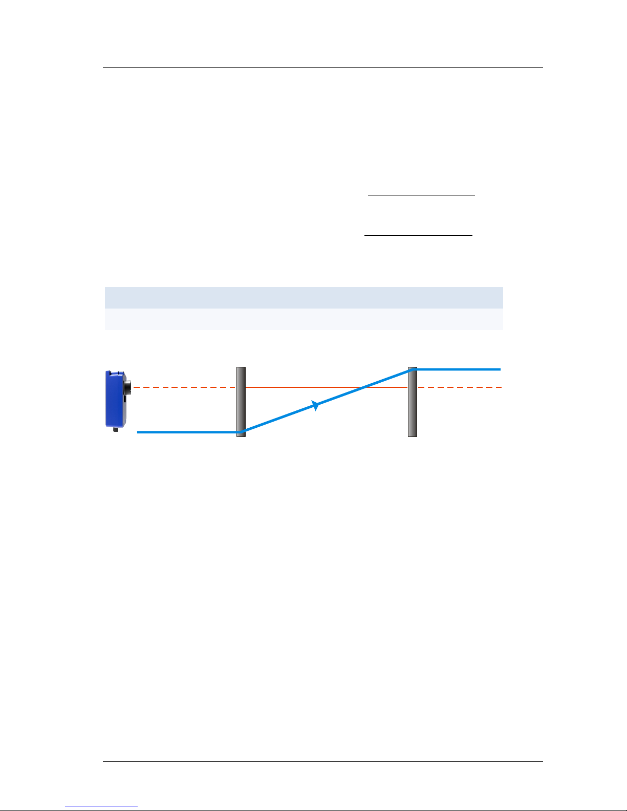
5.3 Analog current output
The purpose of the analog output QA is to allow transmission of measured
values as analogue current value. QA can be configured to a range of
4 mA … 20 mA (factory setting) or 0 mA … 20 mA. In second case the output
current can be transformed to 0-10V by a 500 Ω precision resistor. The
parameter QA_KBYTE controls the current range of QA.
Figure 3 : Wiring diagram of analog output
Page 15
LDS10A Manual Electrical Connection
ASTECH GmbH Page 15
The current is proportional to the measured target distance. This applies
within a distance interval that is marked by the two limiting parameters
QA_LOW and QA_HIGH, where QA_HIGH may be greater or smaller than
QA_LOW. The output current value for 4 mA … 20 mA output is calculated
according to this equation:
QA_LOW < QA_HIGH: IOUT[mA] = 4 mA + 16 ∙ (
Distance − QA_LOW
QA_HIGH - QA_LOW
) ∙ mA
QA_LOW < QA_HIGH: IOUT[mA] = 20 mA - 16 ∙ (
Distance − QA_HIGH
QA_LOW - QA_HIGH
) ∙ mA
Example:
QA_LOW
QA_HIGH
0 m
2 m
4 m
6 m
8 m
10 m
11 m
2 m
10 m
4 mA
4 mA
8 mA
12 mA
16 mA
20 mA
20 mA
QA_LOW
QA_KBYTE = 1 - QA = 0 mA
QA_KBYTE = 2 - QA = 4 mA
QA_HIGH
QA = 20 mA
Figure 4 : Output current and parameter of QA
Page 16
Electrical Connection LDS10A Manual
Page 16 ASTECH GmbH
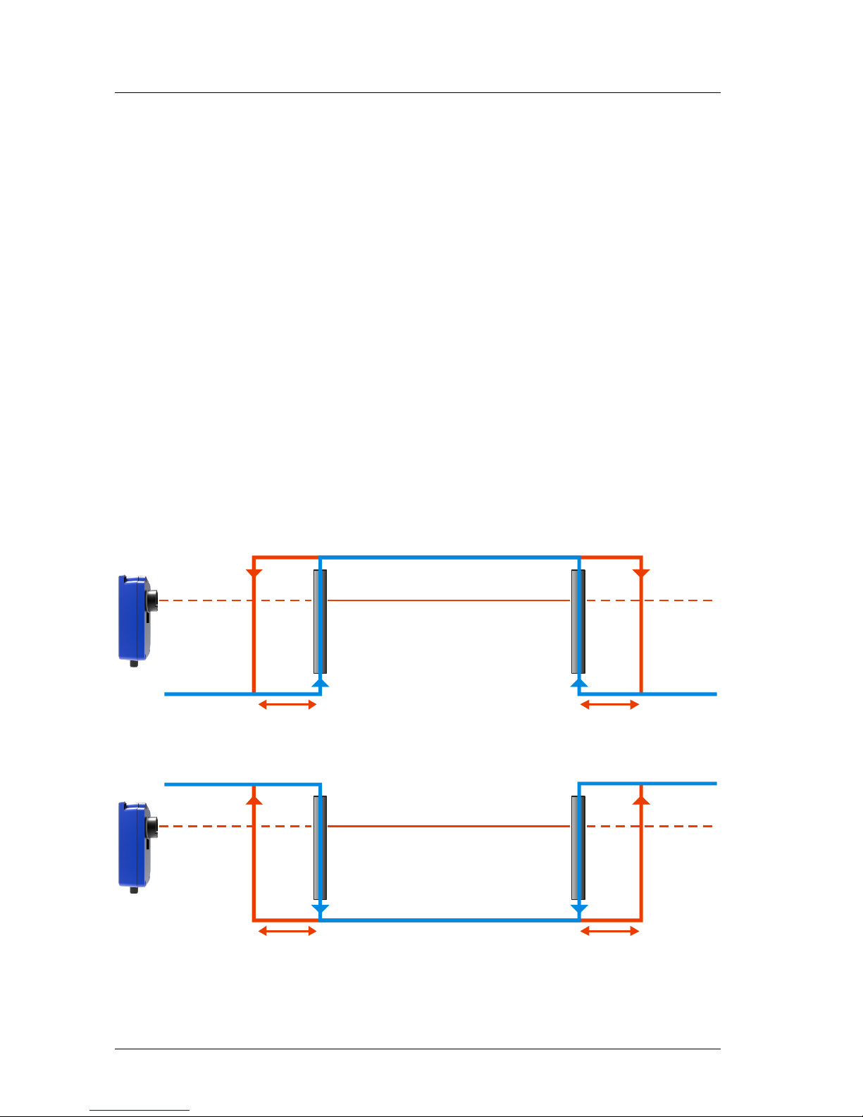
5.4 Digital switching outputs Q1 and Q2
With the help of a user-selectable distance threshold, the switching outputs
Q1 and Q2 can be set to monitor objects or conditions for positive or negative
overstep.
Using the digital switching outputs, objects can be monitored for excision of a
threshold value. To do this, parameter settings for a measurement window
are required. Settings for this window can be made with four parameters:
Qx_ON, Qx_OFF, Qx_HYST, Qx_NONC (x=1 means Q1, x=2 means Q2)
The range which will be subject to monitoring begins at Qx_ON and ends at
Qx_OFF. Switching transitions can be set via parameter Qx_HYST.
All distance parameters are given in millimeters.
The logic state of the switching output is determined by the parameter
QX_NONC. See chapter 7 for more information about parameterization of Q1
and Q2.
Qx_HYST Qx_HYST
Qx_ON
Qx_NONC = 1
Qx_NONC = 0
Qx_OFF
Qx_HYST Qx_HYST
Qx_ON Qx_OFF
Figure 5 : Digital switching output
Page 17
LDS10A Manual Electrical Connection
ASTECH GmbH Page 17
Example:
A moving object is assumed to be monitored with output Q1 in normally open
mode within a window of 8 m to 9 m with a hysteresis of 0.2 m.
Q1_ON = 8000
Q1_OFF = 9000
Q1_HYST = 200
Q1_NONC = 0
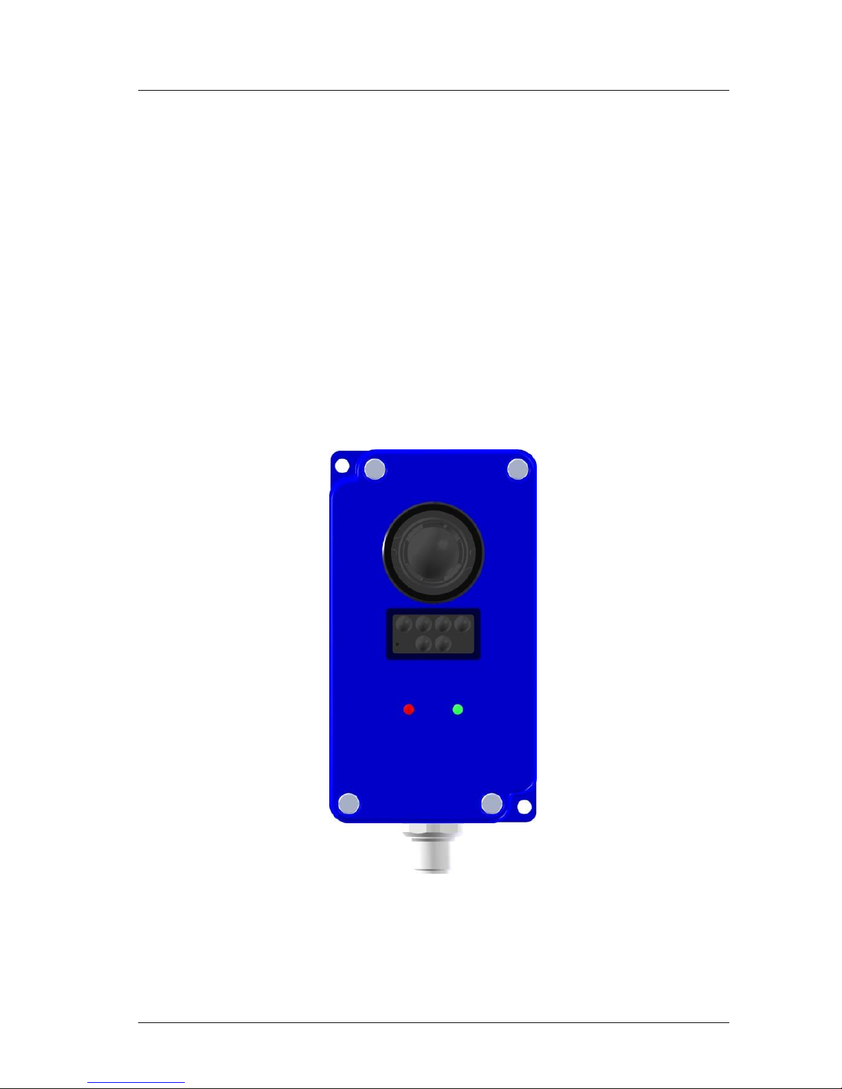
5.5 Device LEDs
There are two multi-color LEDs on the front side of the LDS10A. They are
supposed to signalize the current status without any connected data interface.
Figure 6 : Device LEDs
Meanings of the LED-colors are shown in Table 3 and Table 4.
Status
Output
Page 18

Electrical Connection LDS10A Manual
Page 18 ASTECH GmbH
Table 3 : Meaning of Status-LED signals
Signal
Meaning
Green, blinking
Target reflectivity barely sufficient
Green
Target reflectivity ok
Red, blinking
Temperature warning, temperature 4
Kelvin before end of range
Red
Temperature range exceeded
Blue, blinking
Target reflectivity not sufficient
Blue
Internal communication error
Reset necessary
Off
Output-LED is blinking red
Table 4 : Meaning of Output-LED signals
Signal
Meaning
Green
No output active
Red
Q1 and/or Q2 active
Red blinking
Max. current of Q1 and/or Q2
exceeded
Off
Status-LED is blinking blue
Page 19
LDS10A Manual Start-up and measurement principle
ASTECH GmbH Page 19
6 Start-up and measurement principle
6.1 Start up
Make sure that all cable ends are protected against short circuit effects before
you turn on power supply!
Connect cable terminals as required for the particular operating mode. To
prevent short circuits, you should seal unused cable ends!
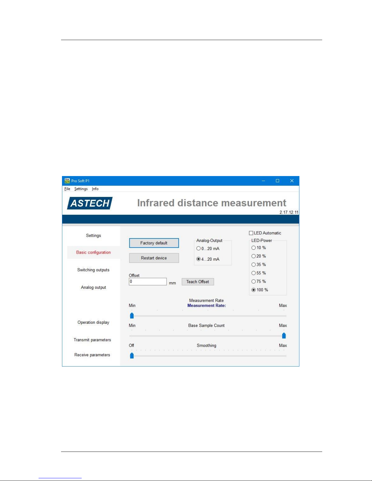
For starting up, a PC with RS485 data interface or suitable USB-to-RS485
converter is required. We recommend the Windows program ProsoftP1
Version 2.17 or higher.
Figure 7 : Program ProsoftP1
As part of preparative actions, the LDS10A must be properly installed in the
designated working site, oriented onto the target and kept in a stable position.
The target to be measured should preferentially have a homogeneous, bright
surface.
Page 20

Start-up and measurement principle LDS10A Manual
Page 20 ASTECH GmbH
6.2 Measurement principle
The measurement principle of the LDS10A consists of a number of separate
data acquisition and processing algorithms.
Signal Acquisition
The signal acquisition module samples the signal of the photodiode element
using a patented oversampling and accumulation strategy to maximize the
signal resolution and the signal to noise ratio. It provides the light intensity
received by the sensor as a function of the time (corresponding to distance
knowing the speed of light) also called full-waveform signal. This fullwaveform signal allows the use of advanced signal processing techniques to
extract the distances of the objects and other useful information about the
scene.
Static Noise Removal
The static noise removal algorithm removes, as its name indicates, the static
noise in the full-waveform signal induced by undesirable light reflections due
to sensor enclosure or electromagnetic interferences. This algorithm increases
drastically the distance measurement accuracy and linearity. The static noise
shape is learned during a calibration procedure during which the waveform of
the signal is captured while the reception lens of the sensor is shielded from
the backscattered light. The sensor comes with a static noise factory
calibration.
Pulse Detection
The objects in the sensor field of detection create a particular signature in the
full-waveform signal called pulses. The pulse detector analyses the fullwaveform signal in order to recognize these pulses and compute their
distance. By nature, time-of-flight sensor using full-waveform analysis is able
to detect several distinct objects with a single photodiode element.
The detected pulses have specific amplitudes based on their distance from the
sensor and on the reflectivity of the objects. It is well known that pulses of
small amplitudes do not lead to accurate and precise distance measurements.
Consequently, the algorithm removes all pulses with amplitudes under a given
threshold.
Page 21

LDS10A Manual Start-up and measurement principle
ASTECH GmbH Page 21
Saturation Compensation
The algorithm classifies the detected pulses based on their shape. The LDS10A
determines which pulses are saturated and which have a normal shape.
Saturated pulse occurs when the signal backscattered by the object is so
strong that the full-waveform signal is clipped. If not treated, this
phenomenon creates an important degradation of the distance measurement
accuracy. It is why a saturation compensation algorithm is executed when
saturated pulses are detected. This innovative algorithm uses a sophisticated
approach to provide distance measurement accuracy better than 10 cm even
with a strongly clipped signal.
Temperature Compensation
The signal processing algorithm also embeds an advanced temperature
compensation scheme which attenuates the distance measurement drift over
large and sudden sensor temperature changes. With this algorithm, the
distance measurements stabilize inside 1 cm in less than 10 seconds on cold
sensor startup. The temperature compensation also ensures optimal accuracy
over the full operating temperature range.
Smoothing
The smoothing algorithm reduces the distance measurement jitter. It can be
seen as a recursive average filter which continuously adapts its cutoff
frequency (or averaging history length) as a function of the current
measurement noise. This innovative algorithm increases the precision of the
device (decreases the standard deviation of the measurements). The level of
smoothing of the algorithm can be adjusted to fit the requirements of the user
applications, please see section7 for more details.
Automatic LED intensity control
The automatic LED intensity control adjusts the intensity of the LEDs in real
time in order to maintain optimal pulse magnitudes at all times. For instance,
if pulses become suddenly saturated, the sensor will decrease automatically
the intensity of the LEDs to a level that ensures optimal distance measurement
accuracy.
Page 22

Start-up and measurement principle LDS10A Manual
Page 22 ASTECH GmbH
6.3 Measurement rate
The sensor acquires a base input waveform at a rate of 72131 Hz
(44MHz/610). Multiple acquisitions are used to perform accumulations and
oversampling and generate a final waveform, which is processed afterwards to
detect the presence of objects and measure their position.
The final measurement rate is therefore:
Measurement rate =
𝑏𝑎𝑠𝑒 𝑟𝑎𝑡𝑒
𝑎𝑐𝑐𝑢𝑚𝑢𝑙𝑎𝑡𝑖𝑜𝑛𝑠 ∙ 𝑜𝑣𝑒𝑟𝑠𝑎𝑚𝑝𝑙𝑖𝑛𝑛𝑔
For example, with 256 accumulations and an oversampling value of 8:
Measurement rate =
72131 𝐻𝑧
256 ∙ 8
= 35.22 𝐻𝑧
Page 23

LDS10A Manual Start-up and measurement principle
ASTECH GmbH Page 23
The configuration software ProsoftP1 automatically calculates the most
suitable combination of accumulations and oversampling according to the
selected measurement rate.
Table 5 : Examples for resulting measurement rate
Accumulation
Oversampling
Measurement rate (Hz)
4096
8
2.20
2048
8
4.40
1024
8
8.81
512
8
17.61
256
8
35.22
128
8
70.44
4096
4
4.40
2048
4
8.81
1024
4
17.61
512
4
35.22
256
4
70.44
128
4
140.88
Measurement rates above 140 Hz will cause unpredicted behavior
of the measurement algorithm.
Page 24

MODBUS-Parameter LDS10A Manual
Page 24 ASTECH GmbH
7 MODBUS-Parameter
7.1 General
The LDS10A data communication interface uses the Modbus RTU protocol
according to standard Modbus specifications. It includes several parameters
which represent all the information from the sensor, measured values and
parameters for the device setup.
Read-only parameters are not allowed to be changed by the user. R/W
parameters are used to change the device setup. Write-only parameters
trigger just internal actions inside the LDS10A. There are not transmitted data.
See chapter 7.5 for the Modbus address references.
7.2 Read-only parameters
Device type number
Device serial number
Device firmware version
Internal temperature
Configuration Byte:
Bit number 2 of the configuration byte indicates the current setup of
the analogue output QA.
Bit 2 = 0: 0-20 mA or 0-10 V
Bit 2 = 1: 4-20 mA
Signal quality
Distance value:
The measured distance value is given by 4 bytes divided into the
MSW (higher 16 bits) and the LSW (lower 16 bits)
Page 25

LDS10A Manual MODBUS-Parameter
ASTECH GmbH Page 25
Status Byte:
The current state of the digital outputs and some additional device
information are given in one byte.
Table 6 : Status byte information
Bit 0
Q1
Bit 1
Q2
Bit 2
Not used
Bit 3
No target
Bit 4
Short circuit
Bit 5
Temperature range exceeded
Bit 6
Not used
Bit 7
Not used
7.3 Write-only parameters
Restore factory settings:
If this parameter is triggered the LDS10A is set back to factory
settings. The setup is stored immediately.
Table 7 : Factory settings of the LDS10A
ACCUMULATIONEXPO
4096
OVERSAMPLING
8
BASESAMPLECOUNT
15
SMOOTHING
-17
LEDCHANGEDELAY
1
LEDPOWERMODE
0
LEDPOWER
100
Q1_ON
250
Q1_OFF
5000
Page 26

MODBUS-Parameter LDS10A Manual
Page 26 ASTECH GmbH
Q1_HYST
100
Q1_NONC
1
Q2_ON
250
Q2_OFF
5000
Q2_HYST
100
Q2_NONC
1
OFFSET
0
Teach:
This parameter triggers the automatic teach of the threshold values
for Q1 and Q2.
Table 8 : Teach byte description
Bit 0
Set Q1_ON
Bit 1
Set Q1_OFF
Bit 2
Set Q2_ON
Bit 3
Set Q2_OFF
Bit 4
Set QA_LOW
Bit 5
Set QA_HIGH
Bit 6
Set Offset
Page 27

LDS10A Manual MODBUS-Parameter
ASTECH GmbH Page 27
7.4 Read/Write parameters
Slave Address
Reads / Writes the slave address of the LDS10A for RS485 mode with
multiple bus access
Accumulation Exponent
The Accumulation Exponent is an important parameter for the
measurement quality. It controls the number of measurements taken
to generate on distance value. Higher values will lead to an enhanced
detection range and reduced noise, but also to a reduced
measurement rate.
Data Format: 12 bit, each bit stands for the corresponding exponent
Range: 0; 1; 2…; 12
Example: Bit 6 = 1; Accumulation = 26 = 64
Oversampling
There are four steps of oversampling available. Small oversampling
will increase measurement rate and noise.
Data Format: 4 bit
Range: 1; 2; 4; 8
Example: Bit 2=1; Oversampling = 4
Base sample count
The number of base sample counts controls the maximum detection
processing range.
Data format: Decimal number
Range: 2 … 15
Page 28

MODBUS-Parameter LDS10A Manual
Page 28 ASTECH GmbH
Smoothing
The behavior of the smoothing algorithm can be adjusted in 32 steps.
Higher values enhance the sensor precision, but reduce the sensor
reactivity. The smoothing algorithm can be deactivated.
Data Format: Decimal number
Range: -16 … +16; -17 = off
The PC parameterization software ProsoftP1 shifts the
data range of the smoothing function to 1 … 33; 0 =
smoothing off.
LED power mode
This parameter selects between automatic or manual LED power
control.
Data Format: 1 Bit (Bit 0)
Range: 0 = manual mode; 1 = automatic mode
LED power
The power of the used infrared illumination LED can be adjusted
manually in 6 steps
Data Format: Percentage as decimal number
Range: 10; 20; 35; 55; 75; 100
LED change delay
The change delay defines the number of frames required before
allowing the sensor to increase or decrease by one the LED power
level. For example, with the same change delay, the maximum rate of
change (per second) of the LED power will be two times higher at
17.6 Hz than at 8.8 Hz.
Data Format: Decimal number
Range: 0 … 65535
Page 29
LDS10A Manual MODBUS-Parameter
ASTECH GmbH Page 29
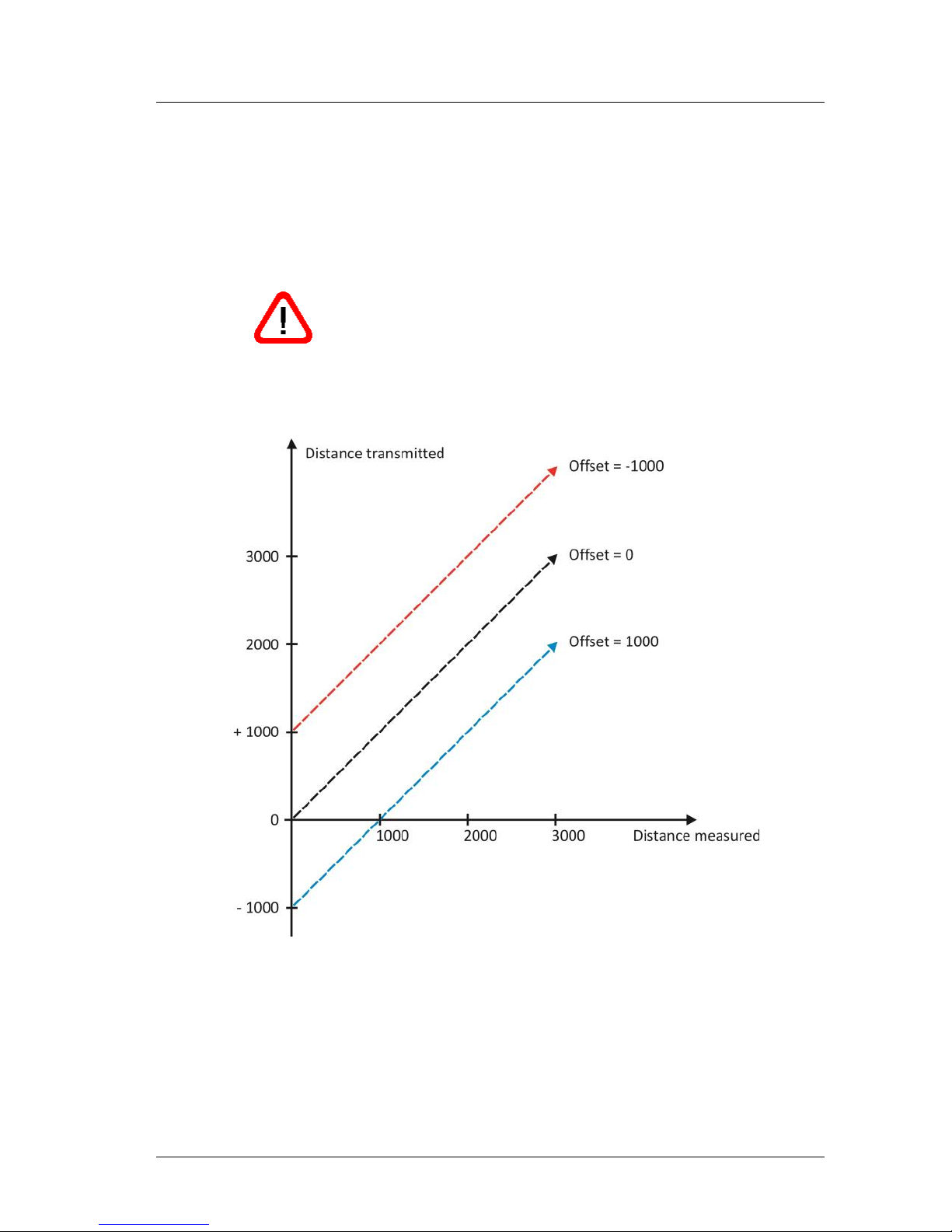
Offset
The offset enables the user to set the zero point for the distance
measurement to a specific point outside the LDS10A. This is helpful
for direct measurements of lengths or deviations starting in front or
behind the LDS10A.
The offset has direct influence on all other parameters
which use the measured distance value.
Data Format: Distance in mm as decimal number
Range: -65535 … 65536
Figure 8 : Example for parameter OFFSET
Page 30

MODBUS-Parameter LDS10A Manual
Page 30 ASTECH GmbH
Qx_ON
Qx_ON sets the distance value where the switching outputs change
their logical state from 0 to 1.
Data Format: Decimal number
Range: -65535 … +65536
Qx_OFF
Qx_OFF sets the distance value where the switching outputs change
their logical state from 1 to 0.
Data Format: Decimal number
Range: -65535 … +65536
Qx_HYST
Ox_HYST selects the hysteresis range for the respective digital
switching output. See section 5.4 for more information.
Data Format: Decimal number
Range: -65535 … +65536
Qx_NONC
Qx_NONC selects the logical switching behavior of the respective
digital output.
Data Format: 1 Bit
Range: 0 = normally open; 1 = normally closed
QA_LOW
QA_LOW selects the starting distance for the analogue output range.
Data Format: Decimal number
Range: -65535 … +65335
Page 31

LDS10A Manual MODBUS-Parameter
ASTECH GmbH Page 31
QA_HIGH
QA_HIGH selects the end distance for the analogue output range.
Data Format: Decimal number
Range: -65535 … +65335
QA_KBYTE
QA_KBYTE selects the operating mode of the analog current output
Data Format: Decimal number
Range: 1 = 0…20 mA / 0…10 V; 2 = 4…20 mA
Page 32

Notice LDS10A Manual
Page 32 ASTECH GmbH
7.5 MODBUS RTU – Register addressing
Table 9 : List of Modbus register addresses
Register-Address
R/W
Description
0
R
Version
1
R
Sub-Version
2
R
Device serial number
3
R/W
Slave address
4
R
Internal temperature
5
R
Maximum temperature
6
R
Minimum temperature
7
W
Factory settings
8
R
Device type ID
9
R
Level of target reflectivity
10
R
Distance value (MSW)
11
R
Distance value (LSW)
21
W
Start bootloader
22
R
Configuration byte (QA)
122
R
Signal Quality
128
R
Status byte
140
R/W
Accumulation Exponent
141
R/W
Oversampling
142
R/W
Base sample count
143
R/W
LED power in %
144
W
Teach-Byte
145
R/W
LED power mode
146
R/W
LED change delay
147
R/W
Smoothing
148
W
Store parameters of sensor module
250
R/W
Q1_ON MSW
251
R/W
Q1_ON LSW
252
R/W
Q1_OFF MSW
253
R/W
Q1_OFF LSW
254
R/W
Q1_HYST
255
R/W
Q1_NONC
Page 33

LDS10A Manual Notice
ASTECH GmbH Page 33
256
R/W
Q2_ON MSW
257
R/W
Q2_ON LSW
258
R/W
Q2_OFF MSW
259
R/W
Q2_OFF LSW
260
R/W
Q2_HYST
261
R/W
Q2_NONC
262
R/W
QA_LOW MSW
263
R/W
QA_LOW LSW
264
R/W
QA_HIGH MSW
265
R/W
QA_HIGH LSW
266
R/W
Offset MSW
267
R/W
Offset LSW
Page 34

Notice LDS10A Manual
Page 34 ASTECH GmbH
8 Part Numbers
Table 10 : Part Numbers
Part-No.
Name
10-2055-00
LDS10A Sensor
15-0044-05
Connection cable M12F8A-open, 5 m
15-0044-10
Connection cable M12F8A-open, 10 m
15-0044-20
Connection cable M12F8A-open, 20 m
15-0048-05
Connection cable M12F8A-open, 5 m, 90°
15-0048-10
Connection cable M12F8A-open, 10 m, 90°
15-0048-20
Connection cable M12F8A-open, 20 m, 90°
11-0001-02
USB-RS485 interface converter for LDS10A
Page 35

LDS10A Manual Notice
ASTECH GmbH Page 35
9 EG Declaration of Conformity
In accordance with the
Directive of Electromagnetic Compatibility 2004/108/EG
The company ASTECH Angewandte Sensortechnik GmbH in Schonenfahrerstr.
5, 18057 Rostock / Germany herewith declare, represented by the signatory,
that the following designated product
LED Distance Sensor
LDS10A
agrees with the following harmonized standard:
IEC 61326-1
Electromagnetic interference and electromagnetic compatibility (EMC)
*including radio interference
Rostock, March 15th 2018
ASTECH Angewandte Sensortechnik GmbH
Jens Mirow
General Manager
Page 36

Notice LDS10A Manual
Page 36 ASTECH GmbH
 Loading...