

Page 1
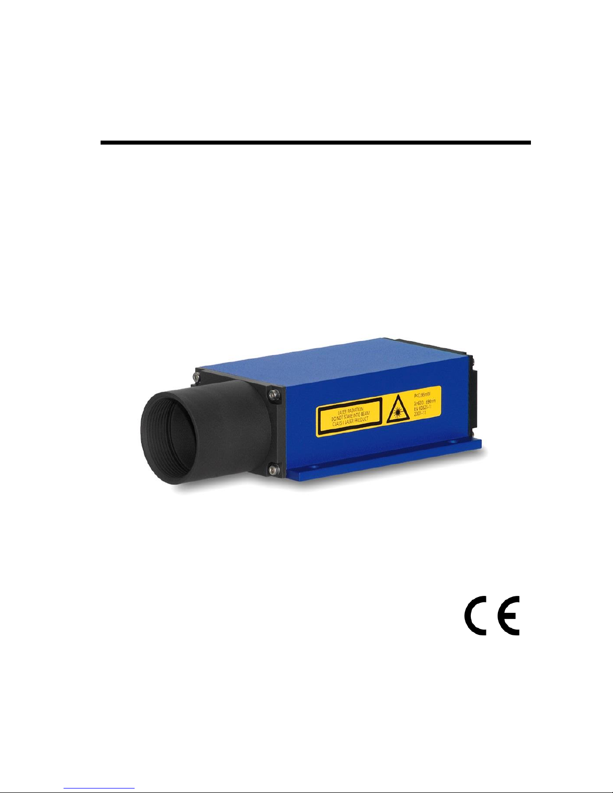
Manual
LDM41E and LDM42E
Version 1.6
Page 2

LDM41E and LDM42E Manual
Page 2 ASTECH GmbH
Dear User,
You are advised to carefully read this User Manual before powering on the
LDM41E and LDM42E Laser distance measuring sensor for the first time.
This is necessary to ensure that you will be able to utilize all the capabilities
and features which your new acquisition provides.
This technology is subject to continuously ongoing development.
Editorial deadline: July 2018
Firmware version: ≥7.05 and 8.06
Manual version: V 1.6
FIle: Manual_LDM41-42E_EN_V1.6.docx
Note:
Proper care has been used in compiling this document. No liability will be
accepted in the event of damage resulting from failure to comply with the
information contained herein.
Revisions history
Manual Version
Date
Changes
1.6
27.07.2018
Max. Trigger voltage
1.5
29.06.2016
E19 added, MTBF
1.4
16.03.2015
New design
ASTECH GmbH, Schonenfahrerstr. 5, D-18057 Rostock
Internet: www.astech.de E-Mail: [email protected]
Phone: +49 (0)381 / 44073-0 Fax: +49 (0)381 / 44073-20
Page 3

LDM41E and LDM42E Manual Content
ASTECH GmbH Page 3
I. Content
1 General ....................................................................................................... 6
2 Safety Instructions ..................................................................................... 8
2.1 General Safety Instructions ............................................................... 8
2.2 Intended & Conforming Use ............................................................. 8
2.3 Nonconforming use ........................................................................... 8
2.4 Laser Classification ............................................................................ 9
2.5 Electric Supply ................................................................................. 10
2.6 Important Operating Advice ........................................................... 10
3 Technical Data .......................................................................................... 11
4 Mechanical Mounting Conditions ............................................................ 13
5 Electrical Connection ............................................................................... 15
5.1 Rear-Side Cover Terminals .............................................................. 15
5.2 Assignment of Terminals ................................................................. 16
5.3 Shield and Grounding ...................................................................... 18
6 Limiting Values for Voltages .................................................................... 19
7 Start up .................................................................................................... 20
7.1 Start up with RS232 ......................................................................... 20
7.2 Start up with Ethernet ..................................................................... 21
8 Commands and Parameter ...................................................................... 23
8.1 General ............................................................................................ 23
8.2 DT – distance tracking ..................................................................... 25
8.3 DS – distance tracking (<7 m) .......................................................... 25
8.4 DW – distance tracking with target board (10 Hz) .......................... 25
8.5 DX – distance tracking with target board (50 Hz) ........................... 26
8.6 DF – distance measurement with external trigger .......................... 26
8.7 DM – distance measurement .......................................................... 27
8.8 TP – internal temperature [°C] ........................................................ 27
8.9 SA – display/set average value [1..20] ............................................ 27
8.10 SD – display/set display format [d/h/s}] ......................................... 27
8.11 ST – display/set measure time [0..25] ............................................. 28
8.12 SF – display/set scale factor ............................................................ 29
Page 4

Content LDM41E and LDM42E Manual
Page 4 ASTECH GmbH
8.13 SE – display/set error mode [0/1/2] ............................................... 30
8.14 AC – display set ALARM center ....................................................... 30
8.15 AH – display/set ALARM hysteresis ................................................ 31
8.16 AW – display/set ALARM width ...................................................... 31
8.17 HO – display/set Temperature for heating on ................................ 31
8.18 HF – display/set Temperature for heating off 17 ............................. 32
8.19 RMx y z – display/set remove measurement.................................. 32
8.20 TDx y – display/set trigger delay trigger level ................................. 33
8.21 TMx y – display/set trigger mode trigger level ............................... 33
8.22 BR – display/set baud rate [2400..38400] ...................................... 35
8.23 AS – display/set autostart command .............................................. 35
8.24 OF – display/set distance offset ...................................................... 35
8.25 SO – set current distance to offset ................................................. 35
8.26 LO – Laser on................................................................................... 36
8.27 LF – laser off .................................................................................... 36
8.28 PA – display settings ....................................................................... 36
8.29 PR – reset settings .......................................................................... 36
9 Interface Connection ............................................................................... 37
9.1 Ethernet .......................................................................................... 37
9.2 Serial Interface RS232 ..................................................................... 39
9.3 Output Format Ethernet and RS232 ............................................... 39
9.4 Digital Switching Output (Alarm) .................................................... 40
9.5 Trigger Input ................................................................................... 42
10 List of Commands .................................................................................... 43
11 Error Codes .............................................................................................. 45
12 EG Declaration of Conformity .................................................................. 46
13 Part Numbers........................................................................................... 47
Page 5

LDM41E and LDM42E Manual Content
ASTECH GmbH Page 5
II. List of Figures
Figure 1 : Measurement principle ...................................................................... 6
Figure 2 : Warning Sign Laser Radiation Class 2 ................................................. 9
Figure 3 : Dimensional drawing ........................................................................ 13
Figure 4 : Offset against zero-edge ................................................................... 14
Figure 5 : LDM41E and LDM42E terminals ....................................................... 15
Figure 6 : Isolated isntallation........................................................................... 18
Figure 7 : Program LDMTool ............................................................................. 21
Figure 8 : Program EtherTool ............................................................................ 22
Figure 11 : Trigger level = 1 ............................................................................... 34
Figure 12 : Trigger level = 0 ............................................................................... 35
Figure 13 : Telnet Program ............................................................................... 37
Figure 14 : LDM41E Sensor Page ...................................................................... 38
Figure 15 : Digital output behavior, positive/negative hysteresis .................... 41
III. List of tables
Table 1 : Technical data .................................................................................... 11
Table 2 : LDM41E and LDM42E terminals......................................................... 15
Table 3 : Pin assignment power supply and trigger .......................................... 16
Table 4 : Pin assignment Fast Ethernet ............................................................. 16
Table 5 : Pin assignment RS232 ........................................................................ 17
Table 6 : Pin assignment programming cable ................................................... 18
Table 7 : Input voltages..................................................................................... 19
Table 8 : Output voltages .................................................................................. 19
Table 10 : Output format LDM41E and LDM42E .............................................. 27
Table 11 : Examples of Scale factor .................................................................. 30
Table 12 : Meaning of SE .................................................................................. 30
Table 13 : Command list LDM41E and LDM42E................................................ 43
Table 14 : Error codes ....................................................................................... 45
Table 15 : Part numbers.................................................................................... 47
Page 6
General LDM41E and LDM42E Manual
Page 6 ASTECH GmbH
1 General
The LDM41E and LDM42E is a Laser sensor to measure distances from 0.1 m to
more than 100 m with pinpoint accuracy.
A given target can be clearly identified with the help of a red Laser sighting
point. In terms of operating reach, the LDM41E and LDM42E performs
depending on the reflectance, morphology and qualities of the target to be
measured.
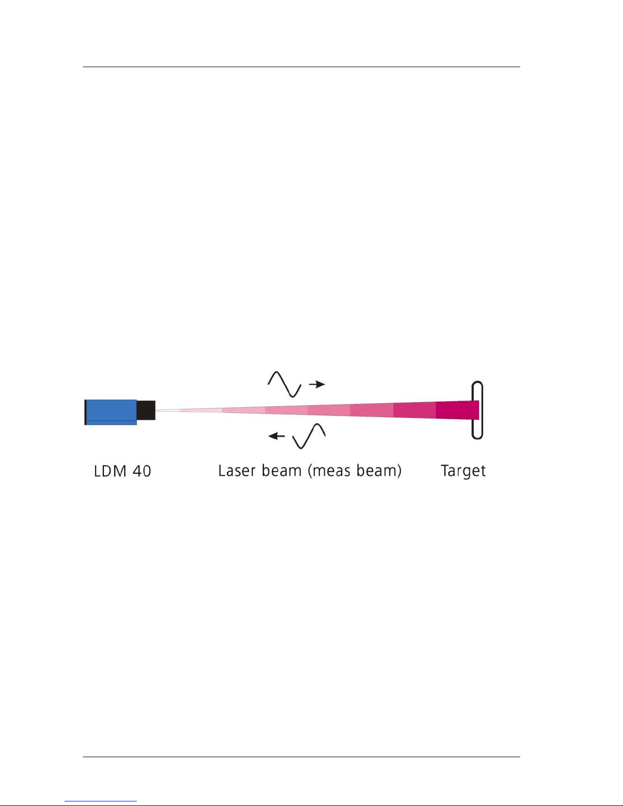
The sensor works based on comparative phase measurement. It emits
modulated Laser light which is diffusely reflected back from the target with a
certain shift in phase to be compared with a reference signal. From the
amount of phase shift, a required distance can then be determined with
millimeter accuracy.
Figure 1 : Measurement principle
A distance measuring cycle can be triggered in three different ways:
By sending a command from the PC or another equivalent control
unit
By making appropriate prior parameter settings for the auto start
command and applying supply voltage
By external triggering (in remote-trigger mode).
For a more detailed description of these three trigger options, you should
consult chapter 8, Commands and Parameter of this User Manual.
Page 7

LDM41E and LDM42E Manual General
ASTECH GmbH Page 7
Special performance features are:
Provides high accuracy and great reach under extreme outdoor
temperatures.
Works in a wide range of operating voltages from 10 V= to 30 V= from an
on-board vehicle supply point, an industrial direct voltage supply net or a
DC power pack.
Features consistently low power consumption of <1.5 W
1
(without I
Alarm
)
Up to 30 m reach for distance measurement, with potential for more than
100 m reach if additional reflectors
2
are mounted onto the target
(depending on reflectance and environmental conditions).
Visible Laser beam for easier sighting.
Fast Ethernet port for input of measuring functions commands from, and
output of measured values to a PC or a PLC (Telnet connection)
Switching output with adjustable limit and hysteresis.
Measured values can be displayed in meters, decimeters, centimeters, feet
and inches due to.
Option for remote triggering of a measurement from an external trigger
device.3
1
inactive internal heating for devices with internal heating (LDM41E-h and LDM42E-h)
2
e.g. 3M, self adhesive foil white non glossy or foil 3290 for longer distances
3
Trigger function is not available for devices with internal heating (LDM41E-h and LDM42E-h)
Page 8

Safety Instructions LDM41E and LDM42E Manual
Page 8 ASTECH GmbH
2 Safety Instructions
2.1 General Safety Instructions
These safety and operating instructions should be carefully read and followed
during practical work with the LDM41E and LDM42E.
There is danger of Laser radiation or electrical shock. For necessary
repair work, the LDM41E and LDM42E may not be opened by anyone
other than Manufacturer personnel. Unauthorized intervention into
the inner product space will void any warranty claims.
Compliance with all specified operating conditions is necessary.
Failure to observe advisory notes or nonconforming product usage may cause
physical injury to the user or material damage to the LDM41E and LDM42E.
Cable connectors must not be plugged or unplugged under voltage.
Remember to turn voltage supply off before you begin working on cable
connections.
2.2 Intended & Conforming Use
Measurement of distances
Special measuring functions
Compliance with prescribed temperatures for operation/storage
Operation at correct voltage level
Application of specified signal levels to the appropriate data lines
2.3 Nonconforming use
Do not operate the LDM41E and LDM42E in any other way than
described under "Intended & Conforming Use" above and only in a
proper working condition
Safety devices must not be defeated or otherwise rendered
ineffective
Information and warning signs must not be removed
Repair work on the LDM41E and LDM42E must not be carried out
by anyone other than authorized personnel.
Page 9
LDM41E and LDM42E Manual Safety Instructions
ASTECH GmbH Page 9
Refrain from using the LDM41E and LDM42E without certified
protection in an explosive environment
Measurement with the LDM41E and LDM42E pointed at the sun or
other strong light sources may produce faulty results
Measurement of targets with poor surface reflectance in a strongly
reflecting environment may also result faulty measurements.
Measurement of strongly reflecting surfaces may deliver faulty
results.
Measurement performed through transparent optical media, for
example glass, optical filters, Plexiglas, etc. may equally produce
incorrect results.
Measurement on translucent objects (materials allow light to pass
through, but are not transparency, e.g. polystyrene, wax, different
plastics etc.) can give a too large measured value, since also light is
reflected by deeper layers
Rapidly changing measuring conditions are likely to falsify the result
of measurement
2.4 Laser Classification
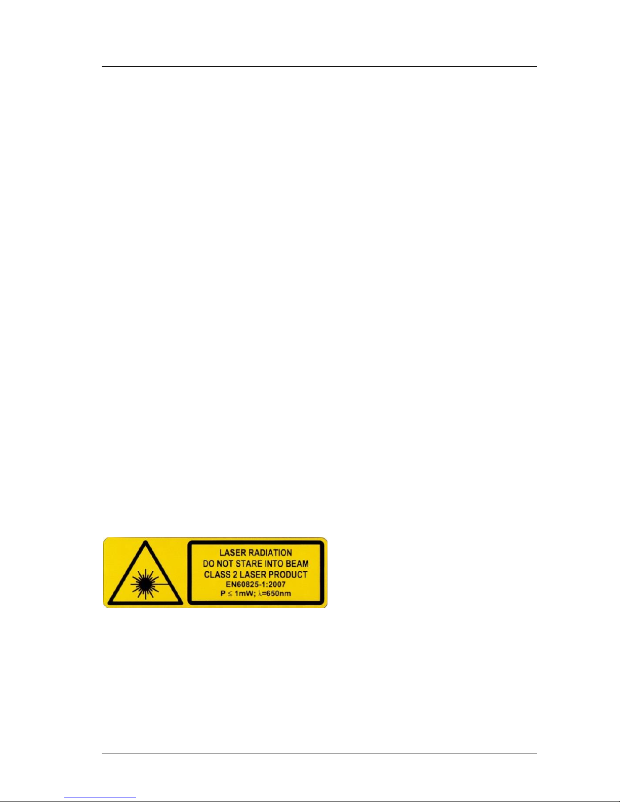
The LDM41E and LDM42E are Class 2 laser product, ≤1 mW as stipulated in
EN60825-1:2007, Class 2.
Caution:
There is Class 2 Laser radiation. Do not stare into beam!
Figure 2 : Warning Sign Laser Radiation Class 2
The Laser power is limited to maximum 1 mW. The Laser radiation is visible. A
short-term exposure (duration up to 0.25 s) is harmless to the eye.
Users are instructed by Laser warning sign (see Figure 2) to do not stare into
the beam. They have to protect themselves by turn the head and/or closing
the eyes and by avoid a long look into the beam.
Page 10

Safety Instructions LDM41E and LDM42E Manual
Page 10 ASTECH GmbH
Do not direct the Laser beam onto persons.
The sensor can use without any additional safety protection.
2.5 Electric Supply
Use only 10 V to 30 V DC (direct voltage) for LDM41E and LDM42E operation.
Use only the specially designated connector terminal for voltage supply.
Specified signal levels must not be exceeded, in order to guarantee correct
data communication.
2.6 Important Operating Advice
To make full use of the system’s inherent performance capabilities and
achieve a long service life, you should always follow these operating rules:
Do not turn the module on if there is fogging or soiling on its optical
parts
Do not touch any of the module's parts with bare hands.
Proceed with care when removing dust or contamination from
optical surfaces!
Prevent shock impacts during transport and use of the LDM41E and
LDM42E
Prevent overheating of the LDM41E and LDM42E.
Prevent major temperature variances during LDM41E and LDM42E
operation
In accordance with IP65 internal protection standards, the LDM41E
an LDM42E is designed to be splash proof and dustproof.
Read these safety and operating instructions with due care and
follow them in practical use.
Page 11

LDM41E and LDM42E Manual Technical Data
ASTECH GmbH Page 11
3 Technical Data
Table 1 : Technical Data
Measurement range4
0.1 m up to 30 m with natural surfaces,
depending on target reflectance or reflectors
more than 100 m achievable5
Measuring accuracy6
2 mm under defined measuring conditions7
3 mm (+15 °C up to +30 °C)
4 mm in DS mode <0.5 m (+15 °C … 30 °C)
5 mm (-10 °C up to +50 °C)
Resolution8
0.1 mm, user scalable, standard 1 mm
Reproducibility
0.5 mm
Measuring time
0.24 to 6 s setup or auto Mode DT
0.1 s (10 Hz) mode DW at white surface
20 ms (50 Hz) mode DX at white surface
(only LDM42E)
Target motion speed
≤4 m/s in DX-Mode (LDM42E only)
Acceleration
≤2,5 m/s² in DX-Mode (LDM42E only)
Operating temperature
-10 °C up to +50 °C
-40 °C up to +50 °C (-h option only)
Storage temperature
-40 °C up to +70 °C
Supply voltage
10 V ... 30 V DC (protected against polarity
reversal)9
Power consumption
Depending on operation mode
< 2.5 W in Standby
< 3.5 W for distance tracking
< 24 W with heating active (-h option only)
Data interface
Fast Ethernet 10/100 Mbit
4
dependent on target reflectance, stray light influences and atmospheric conditions
5
e.g. 3M, self-adhesive foil white, non glossy
6
statistic spread 95 %
7
for measurement at a planar white target surface in continues movement or still standing, +15
up to +30 °C
8
dependent on target reflectance, stray light influences and atmospheric conditions
9
Please use only 24 V DC For devices with heating (LDM41E-h and LDM42E-h) The heater is
connected directly to the power supply.
Page 12

Technical Data LDM41E and LDM42E Manual
Page 12 ASTECH GmbH
and for start-up and service a RS232, baud rate
9600 (2400..38400), ASCII, Format 8N1 (fix)
Digital switching output
„high-side-switch“, programmable switching
threshold and hysteresis, rated for max. load of
0.5 A, HIGH = UB - 2 V, LOW < 2 V
Digital input10
External trigger, trigger pulse 3 up to 20 V, pulse
length≥ 1 ms, start of measurement 5 ms +
trigger delay, trigger slope and delay can be set
(0 ms ... 9999 ms),
EMC
EN 61326-1
Shock resistance
10 g / 6 ms
Persistence shock DIN ISO 9022-3-31-01-1
Laser Class
Laser class 2, under EN60825-1:2007, Class 2
Wave length
650 nm (red visible)
Laser divergence11
0.6 mrad
Laser angle tolerance
Better than ± 1° to the ground plane
MTBF
30,000 h, 24/7, Operation temp +25 °C
Connector
12-pol. M18-male socket, Binder Serie 423
Dimensions (LxWxH)
212 mm x 96 mm x 50 mm
Mounting
100 mm x 85 mm, 4 x M6 holes
Weight
approx. 800 g
Protection class
IP 65 (spatter water and dust protection)
10
trigger function is not available for devices with internal heating (LDM41E-h and LDM42E-h)
11
at 10 m distance the beam diameter is 6 mm, at a distance of 50 m it is 3 cm and at a distance of
100 m it is 6 cm
Page 13
LDM41E and LDM42E Manual Mechanical Mounting Conditions
ASTECH GmbH Page 13
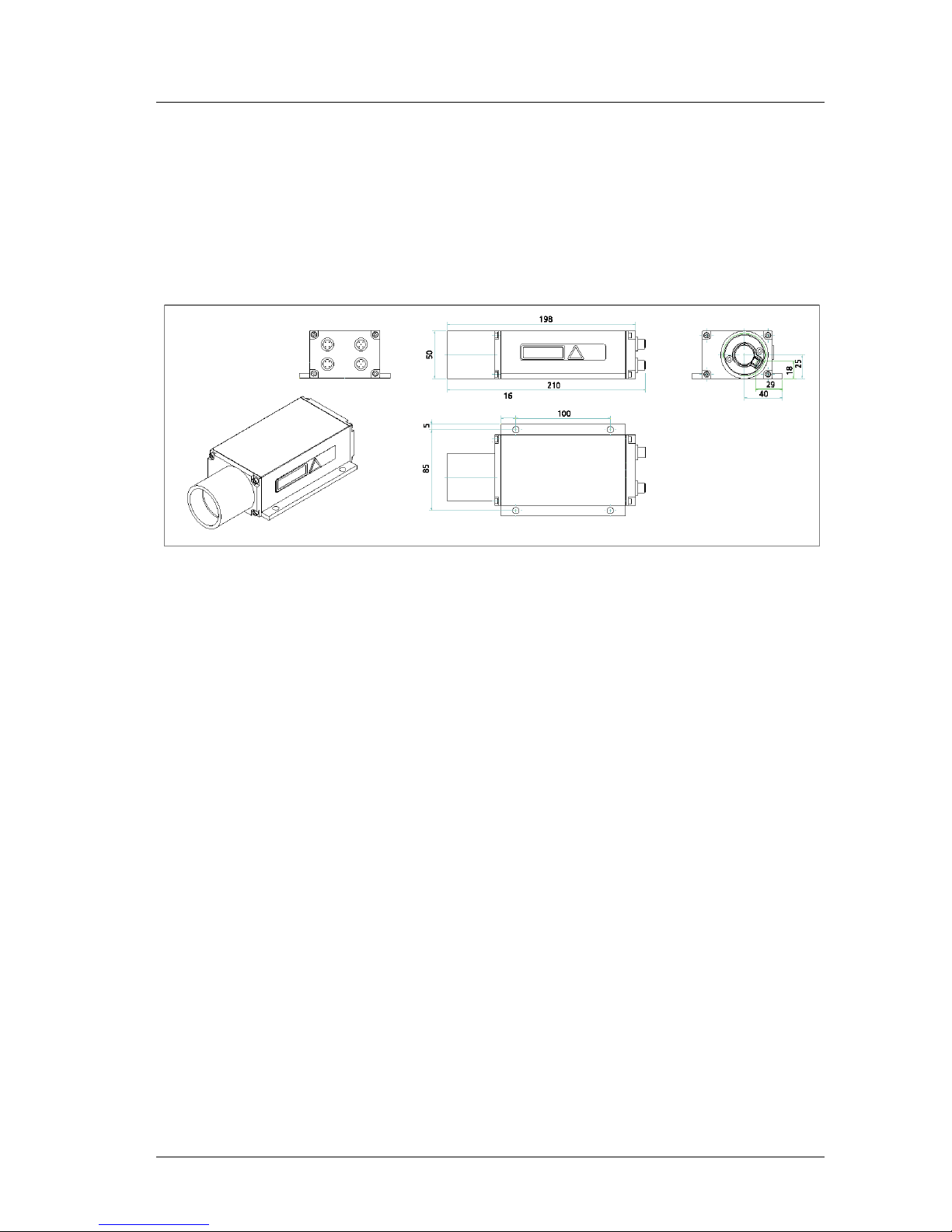
4 Mechanical Mounting Conditions
The casing consists of a rugged, corrosion-resistant extruded aluminum profile
with front-side and rear-side covers also in corrosion-resistant design. Four
mounting holes are provided in the base plate for mechanical attachment of
the LDM41E-h and LDM42E-h.
Figure 3 : Dimensional drawing
To protect the sensor’s optical surfaces from dust, physical contact,
mechanical impacts, etc., the casing has a protection tube attached to it.
Optionally different protection windows and optical filters are available.
Please note that measurement cannot be guaranteed to function correctly if
the equalizer tube is removed by unqualified action!
The interface connector is located on the back cover. Interface cables with
different length are available (standard 2 m, optionally 5 or 10 m).
Page 14
Mechanical Mounting Conditions LDM41E and LDM42E Manual
Page 14 ASTECH GmbH
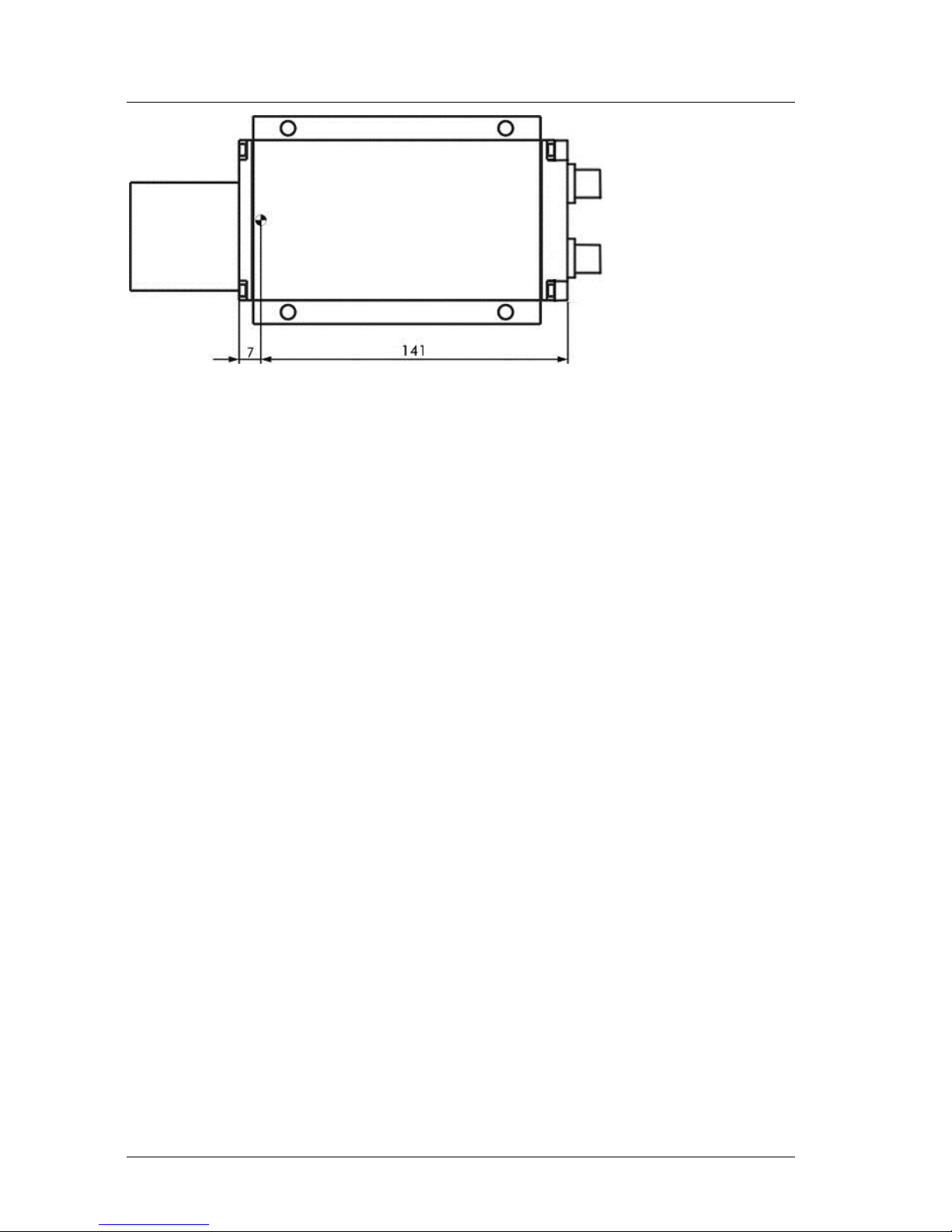
Figure 4 : Offset against zero-edge
The LDM41E and LDM42E’s zero-point is located 7 mm behind the outer
surface of the front cover or 137 mm before the back cover outside face
respectively. This zero-point has been introduced for constructional design
reasons. It can be compensated with the help of parameter “OF“ (see section
8.24 OF – display/set distance offset)
Page 15
LDM41E and LDM42E Manual Electrical Connection
ASTECH GmbH Page 15
5 Electrical Connection
5.1 Rear-Side Cover Terminals
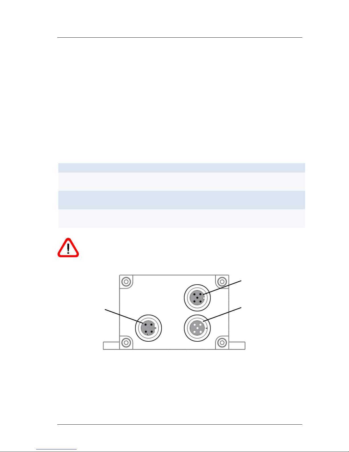
Connector terminals are located on the rear-side cover of the device. The
terminals consist of 4 buses for metal circular plug-in connectors (from
Binder), or compatible connectors, sealed against the casing in compliance
with IP 65 requirements. This connector type guarantees optimised screening
and a high IP level.
The following connection plugs should be used:
Table 2 : LDM41E and LDM42E terminals
Quantity
Connector Type
Use
1
4-pin male cable connector
(series 715 D from Binder)
Fast Ethernet 10/100
1
5-pin male cable connector
(series 713 A from Binder)
RS232
1
5-pin female cable connector
(series 713 A from Binder)
Power supply, switching
output and trigger input
Note: Various connectors and cables are available. Please ensure that
only shielded connectors and shielded cables are used.
Ethernet
RS232
Power supply,
Output and
Trigger-Input
Figure 5 : LDM41E and LDM42E terminals
Page 16

Electrical Connection LDM41E and LDM42E Manual
Page 16 ASTECH GmbH
5.2 Assignment of Terminals
Power Supply
The required power supply is 10 to 30 V DC.
The trigger input allows for a distance measurement via an external signal in
the form of a voltage impulse from 3 to 20 V (only DF mode, please see
Chapter 8).
Table 3 : Pin assignment power supply and trigger
Pin
Description
Colour
Comment
1
VCC
brown
Power supply 10 to 30 V
2
OUT
white
Switching Output
3
GND
blue
Power supply 0 V
4
CONFIG
black
do not use (for service only)
5
TRIGGER
gray
Trigger input 3 to 20 V (ground potential
GND)
Fast Ethernet
The LDM41E and LDM42E has a terminal for circular plug-in connectors (series
715 D for Ethernet from Binder) conforming to the relevant standards.
Table 4 : Pin assignment Fast Ethernet
Pin
Description
Comment
1
TD+
TD+, RJ45: 1 = white/orange
2
RD+
RD+, RJ45: 3 = white/green
3
TD-
TD-, RJ45: 2 = orange
4
RD-
RD-, RJ45: 6 = green
GND wires are connected to an internal collective ground point. They provide
the reference potential for all voltage values quoted below.
Note: Only use connection plugs and Ethernet cables that conform to
the relevant standards
Page 17
LDM41E and LDM42E Manual Electrical Connection
ASTECH GmbH Page 17
RS232 Serial Interface
Note: All commands in Chapter 8 are possible with the RS232 and
also with Ethernet (Telnet)! The use of RS232 can therefore usually be
avoided!
The RS232 interface was originally designed as a PC interface only. It has now
become the standard for serial data transfer for short distances. It is subject to
interference when used for longer distances, in particular, in environments
with interfering high-frequency electromagnetic radiance. As a result, this
interface should only be used for configuring the LDM41E and LDM42E. Please
configure using the programming cable and the LDMTool program.
Note: The receiving line of the RS232 serial interface of the LDM41E
and LDM42E is deactivated while connecting to the Telnet-client. If
the Telnet connection is terminated, the full use of the RS232 is again
possible.
Please observe the RS232 standard. The maximum extension of the
RS232 lines is 15 m.
Table 5 : Pin assignment RS232
Pin
Description
Colour
Comment
1
RxD
brown
Receiving line
2
TxD
white
Transmit line
3
GND
blue
Ground potential
Note: Following successful programming, remove the RS232 cable
and protect the RS232 cable connector with the enclosed sealing plug
against entry of dirt.
Page 18
Electrical Connection LDM41E and LDM42E Manual
Page 18 ASTECH GmbH
Programming Cable
Connection to a PC requires the following cable with SUB-D 9 F connectors.
The TxD and RxD signals of the LDM41E and LDM42E and the PC connection
are crossed. The colours apply to the optional programming cable.
Table 6 : Pin assignment programming cable
Pin LDM 4xE
Description
Colour
Pin SUB-D 9 F
Description
1
RxD
brown
3
TxD
2
TxD
white
2
RxD
3
GND
blue 5 GND
5.3 Shield and Grounding
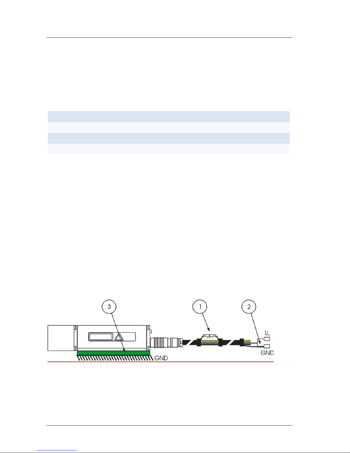
Cable shields must be grounded with low resistance. Only high quality shielded
cables should be used.
Carrier bases and control boxes should have equal potential. Potential
differences could lead to electrical currents and may cause EMC problems (no
correct measurement function or switching the gauge off or on is necessary).
If no potential equalization is possible, then mount the LDM41E and LDM42E
isolated from the carrier base (use nylon screws and washers). Connect the
screen with mass to the cable end. This way of assembly should also be used
when installing the LDM41E and LDM42E inside vehicles
Figure 6 : Isolated isntallation
.
Page 19

LDM41E and LDM42E Manual Limiting Values for Voltages
ASTECH GmbH Page 19
6 Limiting Values for Voltages
GND lines of the power supply and RS232 terminals are connected internally
and form the ground potential for all of the limiting values indicated below.
Input voltages:
Table 7 : Input voltages
Terminal point
Voltage
Comment
VCC
+10 up to +30 V
pole-reversal-protected
CONFIG
do not connect
reserved
TRIG12
± 25 V
short-circuit-proof
RxD
± 25 V
short-circuit-proof
Output voltages:
Table 8 : Output voltages
Terminal point
Voltage
Comment
OUT
like VCC (Ri 135 mΩ)
max. 0.7 A load;
short-circuit-proof
TxD
±5.4 V
short-circuit-proof
Limiting values of voltages, loads and logical levels comply with relevant RS232
and Ethernet standards. All outputs are sustained-short-circuit-proof.
12
Trigger function is not available for devices with internal heating (option –h)
Page 20
Start up LDM41E and LDM42E Manual
Page 20 ASTECH GmbH
7 Start up
Make sure that all cable ends are protected against short circuit effects before
you turn on power supply!
Connect cable terminals as required for the particular operating mode. To
prevent short circuits, you should seal unused cable ends!
As part of preparative actions, the LDM41E and LDM42E must be properly
installed in the designated working site, oriented onto the target and kept in a
stable position. The target to be measured should preferentially have a
homogeneous, bright surface.
Caution: Do not use any retro reflectors!
The alignment of the LDM41E and LDM42E is facilitated by a Laser beam13 that
is visible and can easily be turned on at the PC (e.g. command DT starting the
measurement and switch the Laser on, see 8.2).
7.1 Start up with RS232
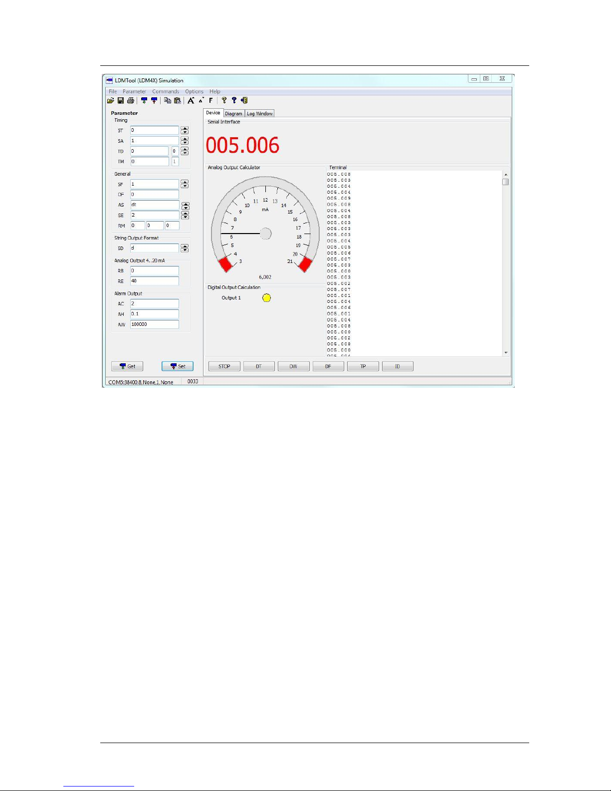
For starting up, a PC with RS232 data interface or a USB converter for RS232
and a terminal program are required. We recommend the Windows program
LDMTOOL Version 4.0 or higher.
13
depending on ambient light and target conditions
Page 21
LDM41E and LDM42E Manual Start up
ASTECH GmbH Page 21
Figure 7 : Program LDMTool
7.2 Start up with Ethernet
The LDM41E and LDM42E come with a default IP address and subnet mask:
IP-Address: 192.168.0.51
Net mask: 255.255.0.0
Alternatively, there is a removable sticker with this information on the device.
Connect the LDM41E and LDM42E over a Switch or Hub to the network.
If the IP address of your PC does not start with 192.168 ... you have to unplug
the PC from the network and change the IP of your PC and establish a local
connection to the PC.
You can discover the IP address of your PC with Start | Run cmd (starting the
command input) and the then command ipconfig.
Page 22
Start up LDM41E and LDM42E Manual
Page 22 ASTECH GmbH
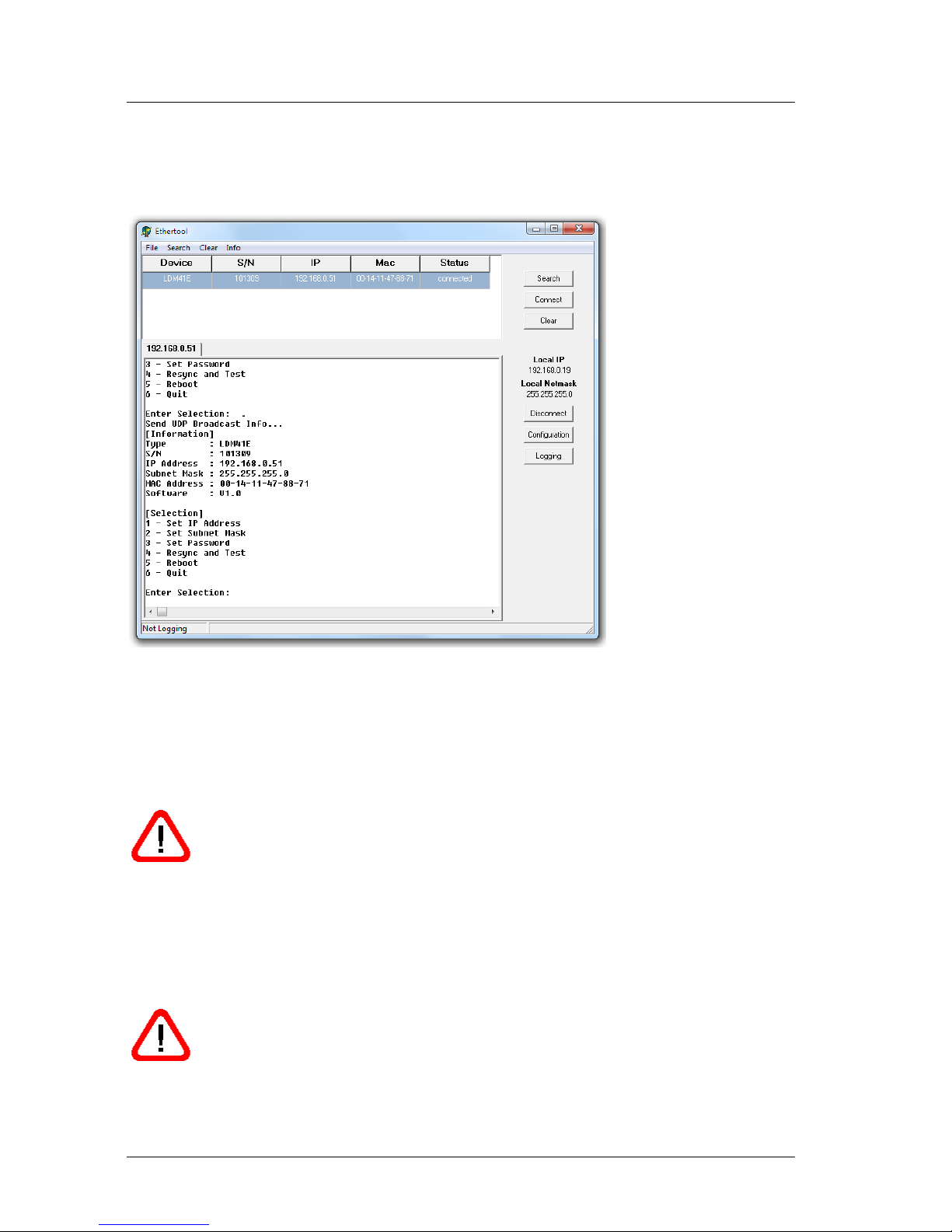
Use the program "EtherTool" by ASTECH and run "Search". Alternatively, start
a telnet client (Windows Telnet, putty or other via TCP/IP port 23) and
connecting you with specifies the IP of the LDM41E and LDM42E.
Figure 8 : Program EtherTool
After Telnet connection is established, you get by entering the "#" in the
configuration mode (see image above). By entering the number corresponding
to [Selection], you can change IP addresses and subnet mask.
Attention: The changed IP addresses and subnet mask is active after a
restart of the device! Then you must re-establish the Telnet
connection.
The configuration mode can be protected by a password. The password must
be at least 4 characters long. If no password characters are entered it will be
cleared.
Attention: Store the password secure and loss protected. The
configuration mode can call no longer without the password!
Page 23

LDM41E and LDM42E Manual Commands and Parameter
ASTECH GmbH Page 23
8 Commands and Parameter
8.1 General
The LDM41E and LDM42E can be parameterized very easy with the PC. The PC
must be equipped with a serial interface RS232 and/or RS232 according to the
attached LDM41E and LDM42E. The use of USB to serially converters is also
possible. An optionally programming cable is necessary. On the PC a terminal
program must be installed (LDMTOOL or HyperTerminal). By selecting
ID[Enter] command, you may call up the menu with available setup commands
(DX[Enter] only LDM42E):
In preparation of a measurement so the sensor can be adapted by intelligent
parameterize optimally to the measuring conditions and the measuring task.
All valid settings will be preserved on turning the LDM41E and LDM42E off!
They can only be replaced with new value entries or changed back to their
standard values by running an initialization routine.
Command entries are not case-sensitive. This means that small and capital
lettering can be used for commands. Any command must be terminated by a
hexadecimal 0Dh (carriage return) character. Where decimal digits are to be
entered, they must be separated by period (2Eh).
For command parameter entries, one must distinguish between parameter
settings and parameter queries. Querying is achieved with a command in
simple format, e.g. (for alarm center parameters):
AC[Enter]
For parameter setting, a new value must be added after the command with no
delimitation sign in between, for example:
AC20.8[Enter]
In the given example, the alarm center will be set to 20.8.
Page 24

Commands and Parameter LDM41E and LDM42E Manual
Page 24 ASTECH GmbH
Note: The LDM41PN and the LDM42PN are not equipped with an
analogue current output. Therefore the configuration commands for
the analogue output cannot be used for the LDM41-42PN. However,
they do ensure compatibility with the LDM41A andLDM42A (without
Profinet).
Page 25

LDM41E and LDM42E Manual Commands and Parameter
ASTECH GmbH Page 25
8.2 DT – distance tracking
Input parameter SA, SD, SE, SF, ST, OF
Output RS232/RS232, digital switching output, analog output
DT mode can be chosen for distance measurement of different kinds of
surfaces (varying reflectance). In this type of distance tracking mode, the
LDM41E and LDM42E uses internal algorithms to continuously evaluate the
quality of the Laser radiation signal that is coming back. This may cause longer
measuring times in the case of poor reflectance or sudden jumps in distance.
The minimum time to measure is 240 ms, the maximum time is 6 s. If the
measuring signal fails to reach a specified quality within six seconds, an error
message is output.
The time to measure may also be limited by setting the ST parameter to a
desired value. ESC stops the measurement.
8.3 DS – distance tracking (<7 m)
Input parameter SA, SD, SE, SF, ST, OF
Output RS232/RS422, digital switching output, analog output
Operation in DS mode makes sense where different types of surfaces have to
be measured at close range up to 7 m. Compared to DT measuring mode, it
allows a higher measurement rate. Within the range from 0.1 m to 0.5 m,
measuring accuracy is restricted (± 4 mm). Measuring time (time to measure)
can be limited via ST parameter settings.
ESC stops the measurement.
8.4 DW – distance tracking with target board (10 Hz)
Input parameter SA, SD, SE, SF, OF
Output RS232/RS422, digital switching output, analog output
DW mode performs at a steady measuring rate of 10 Hz. As a necessary
precondition for measured values to be stable, a white target board must be
placed at the selected object. There must be no sudden jumps in distance
greater than 16 cm within the measuring field!
ESC stops the measurement.
Page 26

Commands and Parameter LDM41E and LDM42E Manual
Page 26 ASTECH GmbH
8.5 DX – distance tracking with target board (50 Hz)
Input parameter SA, SD, SE, SF, OF
Output RS232/RS422, digital switching output, analog output
DX mode performs at a steady measuring rate of 50 Hz (only LDM42). As a
necessary precondition for measured values to be stable, a white target board
must be placed at the selected object.
This measurement mode is intended in the first place for objects performing
homogeneous motion up to 4m/s. For higher rates of measurement,
preceding measured values will be included in the process to calculate a
currently measured value. There must be no sudden jumps in distance greater
than 16 cm within the measuring field!
Caution: To prevent transmission problems, please use 9600 baud
as the minimal baud rate for DX Mode!
8.6 DF – distance measurement with external trigger
14
Input parameter SD, SE, SF, ST, OF, TD, ST, SA, RM
Output RS232/RS232, digital switching output, analog output
DF mode allows a measurement that is triggered by an external trigger pulse.
Initially, after selecting this mode, the operator does not receive any response.
As soon as the trigger pulse has been detected, the LDM41E and LDM42E will
send data and switches to digital and/or analog output.
Settings for trigger delay (delay) and trigger slope can be defined via
parameter TD (see 8.20 TDx y – display/set trigger delay trigger level).
With ST=1 the maximum trigger frequency should not exceed 3.5 Hz.
14
Trigger function is not available for devices with internal heating (option -h)
Page 27

LDM41E and LDM42E Manual Commands and Parameter
ASTECH GmbH Page 27
8.7 DM – distance measurement
Input parameter SD, SE, SF, ST, OF
Output RS232/RS232, digital switching output, analog output
DM mode triggers a single measurement (single shot)
8.8 TP – internal temperature [°C]
TP queries the value of the inner LDM41E and LDM42E temperature.
Note: In tracking mode, the inner temperature may exceed the surrounding
temperature level by as much as 10 K.
8.9 SA – display/set average value [1..20]
SA allows you to calculate a floating average value from 1 to 20 measured
values. Calculation is based on this formula:
Average value:
Standard setting is 1 (no average).
8.10 SD – display/set display format [d/h/s}]
SD selects the output format of measured value data. There are three modes
available:
Table 9 : Output format LDM41E and LDM42E
Parameter
Output
Format
d
decimal
xxx.xxx<CR><LF>
x=0…9
h
hexadecimal
<SPACE>xxxxxx<CR><LF>
x=0...F
s
decimal with signal quality
xxx.xxx<SPACE>yyyyyy<CR><LF>
x=0…9; y=0…9
SD affects all commands that output a distance value.
An output value is calculated from a given measured distance value (in mm),
multiplied by the scale factor SF.
Page 28

Commands and Parameter LDM41E and LDM42E Manual
Page 28 ASTECH GmbH
Negative distance values are output in two’s complement notation.
The value for the signal quality varies between 0 and 1024. 0 means a bad
signal quality while 1024 indicates a very good signal quality.
Examples:
Distance = 4,996 m, SF1
dec: 004.996<CR><LF>
hex: <SPACE>001384<CR><LF>
(= 4996 mm × SF1)
dec+sig: 004.996_000005<CR><LF>
(bad signal quality)
dec+sig: 004.996_000985<CR><LF>
(good signal quality)
Distance = 4,996 m, SF10
dec: 049.960<CR><LF>
hex: _00C328<CR><LF>
(= 49960 = 4996 mm × SF10)
dec+sig: 049.960_000005<CR><LF>
Error case
dec/hex: E15<CR><LF>
(see 11 Error Codes)
8.11 ST – display/set measure time [0..25]
Measuring time is directly conditional on the selected measuring mode. As a
general rule, one may say: the poorer the reflectance of the surface of a
particular target, the more time the LDM41E and LDM42E will require to
determine the distance with specified accuracy. For example, if error message
E15 is output because of poor reflectance and insufficient time to measure,
this latter setting must be increased.
Page 29

LDM41E and LDM42E Manual Commands and Parameter
ASTECH GmbH Page 29
The available value range for measuring time is 0 to 25. Basically, the greater
the time setting is the more time will be available for measurement and the
lower the resulting measuring rate.
An exception there from is zero-value. In this case, the LDM41E and LDM42E
automatically picks the smallest possible time value for measurement!
The LDM41E and LDM42E comes factory-set with ST = 0.
ST is effective in the DT, DF and DM mode of operation.
The measuring time setting option can also be used to modify the measuring
rate, for example, in order to restrict the data volume or for synchronization
purposes. Measuring time can only be set as an approximate value, because
the underlying principle of measurement is subject to certain variances that
cannot be accounted for:
DT measuring mode → measuring time= ST x 240 ms (except ST = 0)
DS measuring mode → measuring time = ST x 150 ms (except ST = 0)
Example:
The target distance is 25 m, but the target’s reflectance is not ideal. With a
measuring time setting of ST 2, E15 will be output following measurement.
The user must increase the time (ST > 2) or set auto (ST 0) to measure in this
case!
One should work in DW or DX measuring mode where stable
measuring times are required.
8.12 SF – display/set scale factor
SF multiplies a calculated distance value with a user-selectable factor for
changes in resolution or outputs in a different unit of measure. The scale
factor may also be negative. Standard setting is 1.
The scale factor influence the output of measurement results, Offset (OF),
Alarm Centre (AC), Alarm Hysteresis (AH), Range Begin (RB) and Range End
(RE)!
Page 30
Commands and Parameter LDM41E and LDM42E Manual
Page 30 ASTECH GmbH
Table 10 : Examples of Scale factor
Scale factor
Resolution
Output
Output Unit
SF1
1 mm
012.345
m
SF10
0.1 mm
123.450
dm
SF1.0936
0.01 yard
013.500
yard
SF3.28084
0.01 feet
040.501
feet
SF0.3937
1 inch
004.860
100 inch
SF-1
1 mm
-12.345
m
Note: Following a change in the scale factor, the settings for digital
and/or analog output and offset must be matched accordingly!
8.13 SE – display/set error mode [0/1/2]
SE (error mode) allows you to configure the behavior of the digital switching
output (alarm) and/or the analog output following an error message (E15, E16,
E17). Depending on the particular LDM41E and LDM42E application
environment, error messages have to be handled in different ways.
Available setting options are 0, 1 and 2 with the following effects in the case of
an error:
Table 11 : Meaning of SE
SE
Digital switching output (Alarm)
Analog output (4 -20 mA)
0
ALARM of latest valid
measurement
Outputs current of last valid
measurement
1
Positive alarm hysteresis = LOW
Negative alarm hysteresis = HIGH
RE >RB: Current =3 mA
RE <RB: Current =21 mA
2
Positive alarm hysteresis = HIGH
Negative alarm hysteresis = LOW
RE >RB: Current =21 mA
RE <RB: Current =3 mA
8.14 AC – display set ALARM center
AC sets the beginning of the distance range, for which the switching output
will be turned active. The length of this active range can be set using the AW
parameter.
Page 31

LDM41E and LDM42E Manual Commands and Parameter
ASTECH GmbH Page 31
AC must be selected in keeping with the currently set SF scale factor (see 9.4
Digital Switching Output (Alarm)).
8.15 AH – display/set ALARM hysteresis
AH allows you to make parameter settings for the switching hysteresis at the
beginning and the end point of the active range of the switching output.
AH must be selected so it is properly matched to the currently valid scale
factor (SF).
The mathematical sign of AH can be used to set an active state logic level:
Positive sign (“+”): active range is HIGH-active.
Negative sign (“-“): active range is LOW-active.
No sign setting means positively-signed (see 9.4 Digital Switching Output
(Alarm)).
8.16 AW – display/set ALARM width
AW sets the length of the active range, beginning at AC.
AW settings must be made in agreement with the currently valid SF scale
factor.
AW is always equal or greater than “0” (zero).
AW is always equal or greater than |AH| (the amount of AH).
Standard setting is 100000 – means off.
8.17 HO – display/set Temperature for heating on
15
HO displays/sets the temperature value at which the internal heating is
switched on. The values can be varied between -40°C and 70°C.
Standard setting is 3°C.
15
Only for devices with internal heating (option -h)
Page 32

Commands and Parameter LDM41E and LDM42E Manual
Page 32 ASTECH GmbH
8.18 HF – display/set Temperature for heating off
15
HF displays/sets the temperature value at which the internal heating is
switched off. The values can be varied between -40°C and 70°C. Standard
setting is 12°C.
8.19 RMx y z – display/set remove measurement
Standard setting: 0 0 0
RM is intended to facilitate settings for a range of expected distance values.
Values which are found to be outside of this expected range will be corrected
until matching the most recently valid measured values.
RM is only effective in DT mode.
It consists of three parameters which are separated by space (20h).
x designates the number of preceding measured values that will be
evaluated in the case of non-conforming measurement. A maximum
of ten preceding measured values can be evaluated.
y defines the range of permissible values. If this range is exceeded in
negative or positive direction, the respective measured value will be
corrected accordingly.
z stands for the number of values that are out of the permissible value
range (out of tolerance values). In the event of out-of-tolerance
values arriving in succession, the most recently corrected value will
be included in the correction process for the next out-of-tolerance
value. The maximum allowed number of out-of-tolerance values is
100.
Important: The use of RM parameter settings should be restricted
to suitable applications only. Improper use of the parameter may
create safety hazards!
Page 33

LDM41E and LDM42E Manual Commands and Parameter
ASTECH GmbH Page 33
8.20 TDx y – display/set trigger delay trigger level
16
TD is only intended for the configuration of the remote trigger input (see 8.6
DF – distance measurement with external trigger).
TD consists of two sub parameters, of the actual delay value, i.e. the delay
time, and the trigger level.
Trigger delay corresponds to the time from arrival of the trigger signal to the
starting point of a measurement. It may be set to any value between 0 and
9999 ms. With the help of the trigger level one may define if measurement is
to begin on a rising or a falling pulse slope.
Trigger delay and trigger level must be separated by space (20h) in the entry
line. Standard setting: 0 0.
x Delay time between trigger signal and start of measurement, delay
can be set from 0 to 9999 ms.
y 0 for HIGH → LOW-slope
1 for LOW → HIGH-slope
Example:
TD1000_0[Enter]
In the given example, the delay has been set to 1000 ms and the trigger slope
to "rising" (LOW-to-HIGH transition)
8.21 TMx y – display/set trigger mode trigger level
17
TM provides parameter setting options for the auto-start trigger function
which allows external triggering of the auto-start command that was set via
parameter AS. Triggering is accomplished via the external trigger input. All
starting modes which are selectable via AS can be launched and stopped by
external triggering. These are: DS/DT/DW/DX/DF/DM/TP/LO/ID.
TM consists of two parameters which are separated by space (20h).
x 0... Trigger function turned off
16
Trigger function is not available for devices with internal heating (option -h)
17
Trigger function is not available for devices with internal heating (option -h)
Page 34
Commands and Parameter LDM41E and LDM42E Manual
Page 34 ASTECH GmbH
1... Trigger function turned on
y 0 ... measurement is triggered on trigger line at L-level
(HIGH → LOW slope)
1 ... measurement is triggered on trigger line at H-level
(LOW → HIGH slope)
Standard setting is TM0 1.
For triggering, the trigger level must be permanently applied!
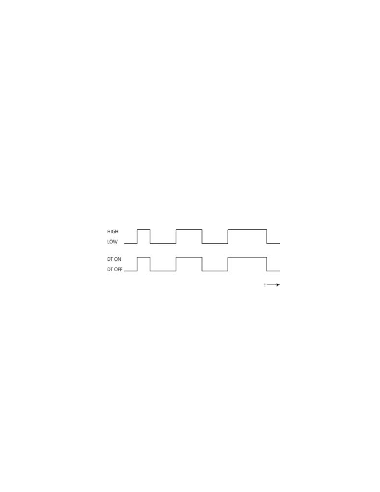
Examples:
a) ASDT
TM1 1
Trigger signal = H → DT is performed
Trigger signal = L → DT is stopped
Figure 9 : Trigger level = 1
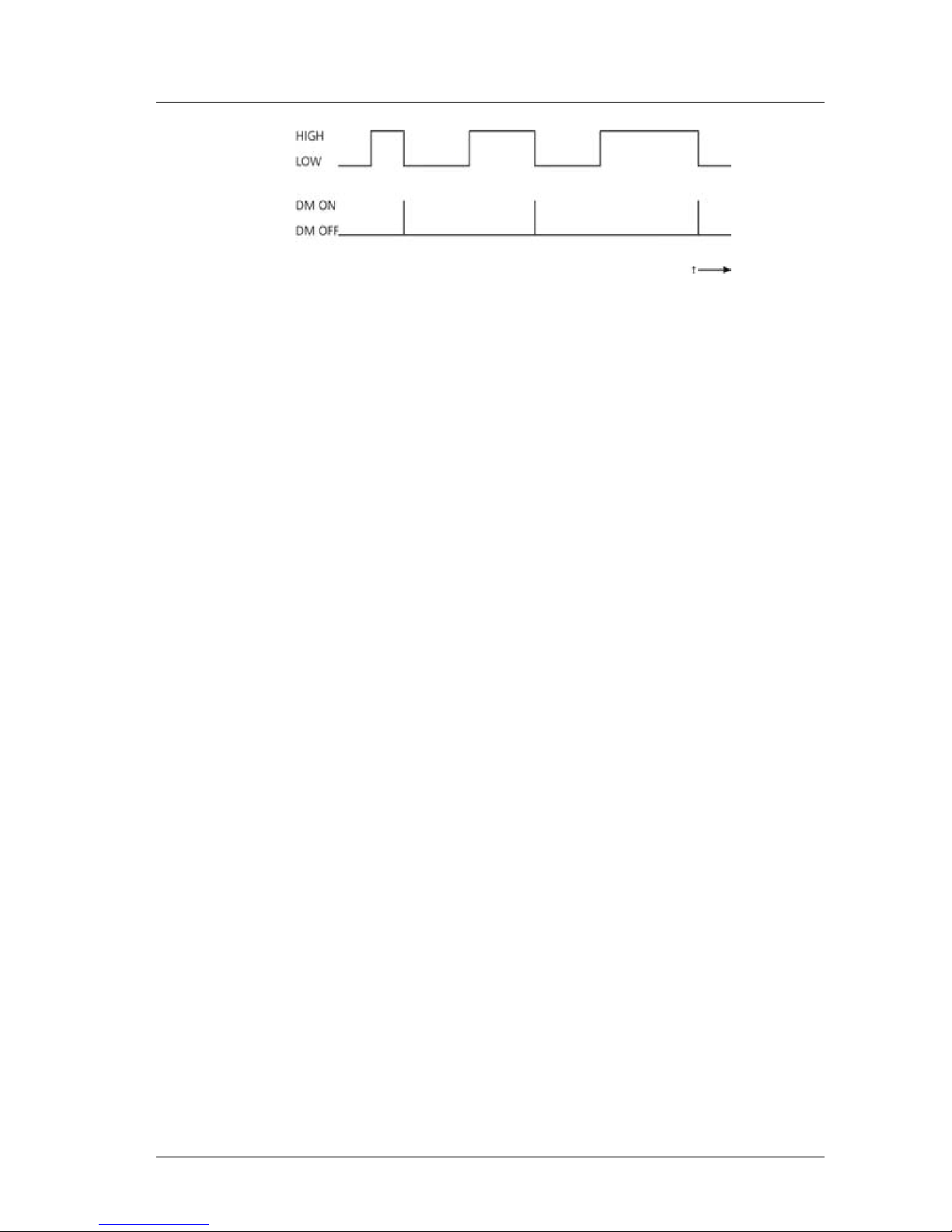
b) ASDM
TM1 0
Trigger signal=H → no change in state
Trigger signal=L → DM active, i.e. one measurement is
triggered
Page 35
LDM41E and LDM42E Manual Commands and Parameter
ASTECH GmbH Page 35
Figure 10 : Trigger level = 0
8.22 BR – display/set baud rate [2400..38400]
Available baud rate settings are: 2400, 4800, 9600, 19200, 38400. Faulty
entries will be rounded to the nearest baud rate. A fixed data format of eight
data bits, with no parity and one stop bit is used. Standard setting is 9600
baud.
8.23 AS – display/set autostart command
AS (auto start) defines which function will be carried out when power
becomes available to the LDM41E and LDM42E.
Possible entries are those delivering a measured value on the output side, an
ID command or the command for turning the Laser on (LO).
For example, if ASDT has been parameterized, the LDM41E and LDM42E will
begin with distance tracking on turning on power.
8.24 OF – display/set distance offset
With the help of OF (offset) the user may define a zero-point for his/her
application. For details about the position of the module’s zero-point, refer to
section 4. OF has to match the current valid scale factor setting (SF).
OF may also take on negative values. Standard setting is0
8.25 SO – set current distance to offset
SO performs a distance measurement and saves the measured reading as an
offset value with inverted mathematical sign (OF).
Page 36
Commands and Parameter LDM41E and LDM42E Manual
Page 36 ASTECH GmbH
8.26 LO – Laser on
LO turns the Laser on. This function can be used for orientation or functional
testing of the LDM41E and LDM42E. After the command LO it’s necessary to
send LF! Don’t use LO because this. Please use instead of LO the command DT
to turn the Laser on.
8.27 LF – laser off
LF turns the Laser off.
8.28 PA – display settings
PA lists all parameters in a table.
8.29 PR – reset settings
PR resets all parameters (except baud rate). After this a new configuration of
the LDM41E and LDM42E is necessary
average value[SA].................1
display format[SD]................d
measure time[ST]..................0
scale factor[SF]..................1
error mode[SE]....................1
ALARM center[AC]..................1000
ALARM hysterese[AH]...............0.1
ALARM width[AW]...................100000
distance of Iout=4mA [RB].........1000
distance of Iout=20mA [RE]........2000
remove measurement [RM]...........0 0 0
trigger delay, trigger level[TD]..0 0
trigger mode, trigger level[TM]...0 1
baud rate[BR].....................9600
autostart command[AS].............ID
distance offset[OF]...............0
Use instead of PR the "Set Standard" command from Windows
program LDMTool.
Page 37
LDM41E and LDM42E Manual Interface Connection
ASTECH GmbH Page 37
9 Interface Connection
9.1 Ethernet
Ethernet is the most widely used standard for wired networks. The LDM41E
and LDM42E realized Fast Ethernet with 100 MBit / s.
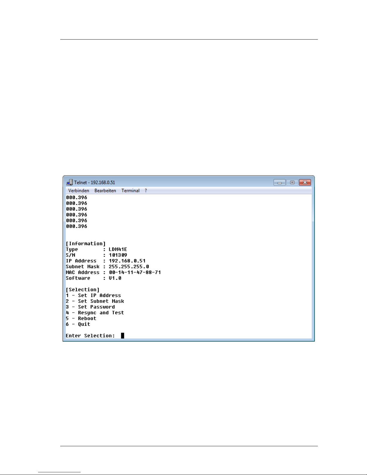
The data is transmitted using Telnet (port 23). This must be established with a
Telnet client connects to the Telnet server in the LDM41E and LDM42E. The
program EtherTool provides an integrated telnet client.
The commands are described in chapter 8 starting page23. The data output
format is determined by parameter SD (display format), see page 27.
Figure 11 : Telnet Program
Page 38
Interface Connection LDM41E and LDM42E Manual
Page 38 ASTECH GmbH
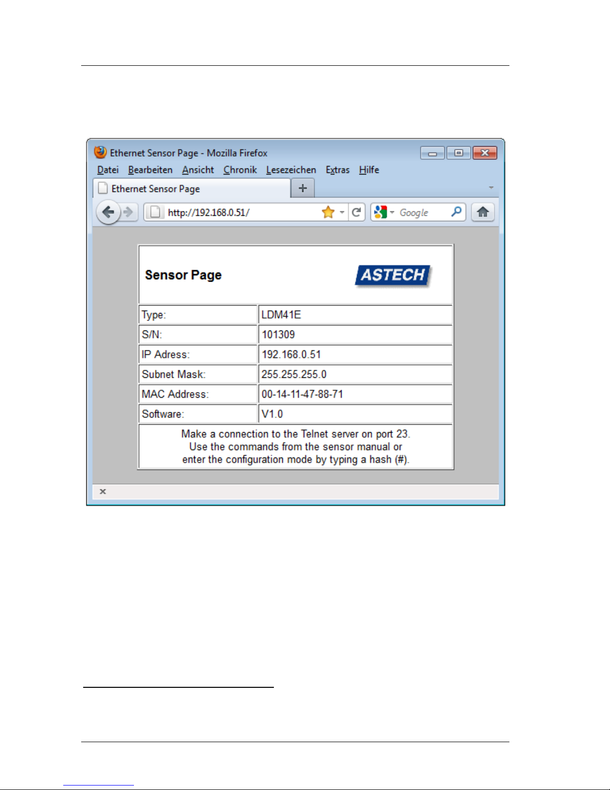
The device can also be accessed via a browser (Firefox, Internet
Explorer18 etc.) via http (port 80). Only one browser can assess to the
HTML page at the same time. Inputs are not available!
Figure 12 : LDM41E Sensor Page
18
With the Internet Explorer select at first under "Tools | Security | Internet Options" the option
"Local Intranet" and then click on "Sites". In the new window must be clicked on "Advanced" and
in the next window add the IP address of the LDM, for example: "http://192.168.0.51".
Page 39

LDM41E and LDM42E Manual Interface Connection
ASTECH GmbH Page 39
9.2 Serial Interface RS232
Initially, RS232 communication interfaces purely functioned as PC
communication ports. They have become the established standard tool for
serial data transmission over short cable lengths. With greater transmission
lengths, the interface is highly susceptible to interferences, notably, in the
vicinity of strong electromagnetic noise emitters.
Therefore, it should only be used for LDM41E and LDM42E configuration.
The commands of the serial interface are described in chapter 8 starting page
23. The data output format is determined by parameter SD (display format),
see page 27.
9.3 Output Format Ethernet and RS232
The output format on the serial interface is selected by the command SD.
There are three modes available:
Parameter
Output
Format
d
decimal
xxx.xxx<CR><LF>
x=0…9
h
hexadecimal
<SPACE>xxxxxx<CR><LF>
x=0...F
s
Decimal with signal
quality
xxx.xxx<SPACE>yyyyyy<CR><LF>
x=0…9; y=0…9
SD affects all commands that output a distance value.
An output value is calculated from a given measured distance value (in mm),
multiplied by the scale factor SF.
Negative distance values are output in two’s complement notation.
The value for the signal quality varies between 0 and 1024. 0 means a bad
signal quality while 1024 indicates a very good signal quality.
Examples:
Distance = 4,996 m, SF1
dec: 004.996<CR><LF>
hex: <SPACE>001384<CR><LF>
(= 4996 mm × SF1)
Page 40

Interface Connection LDM41E and LDM42E Manual
Page 40 ASTECH GmbH
dec+sig: 004.996_000005<CR><LF>
(bad signal quality)
dec+sig: 004.996_000985<CR><LF>
(good signal quality)
Distance = 4,996 m, SF10
dec: 049.960<CR><LF>
hex: _00C328<CR><LF>
(= 49960 = 4996 mm × SF10)
dec+sig: 049.960_000005<CR><LF>
Error case
dec/hex: E15<CR><LF>
(see page 45, chapoter 11, Error Codes)
9.4 Digital Switching Output (Alarm)
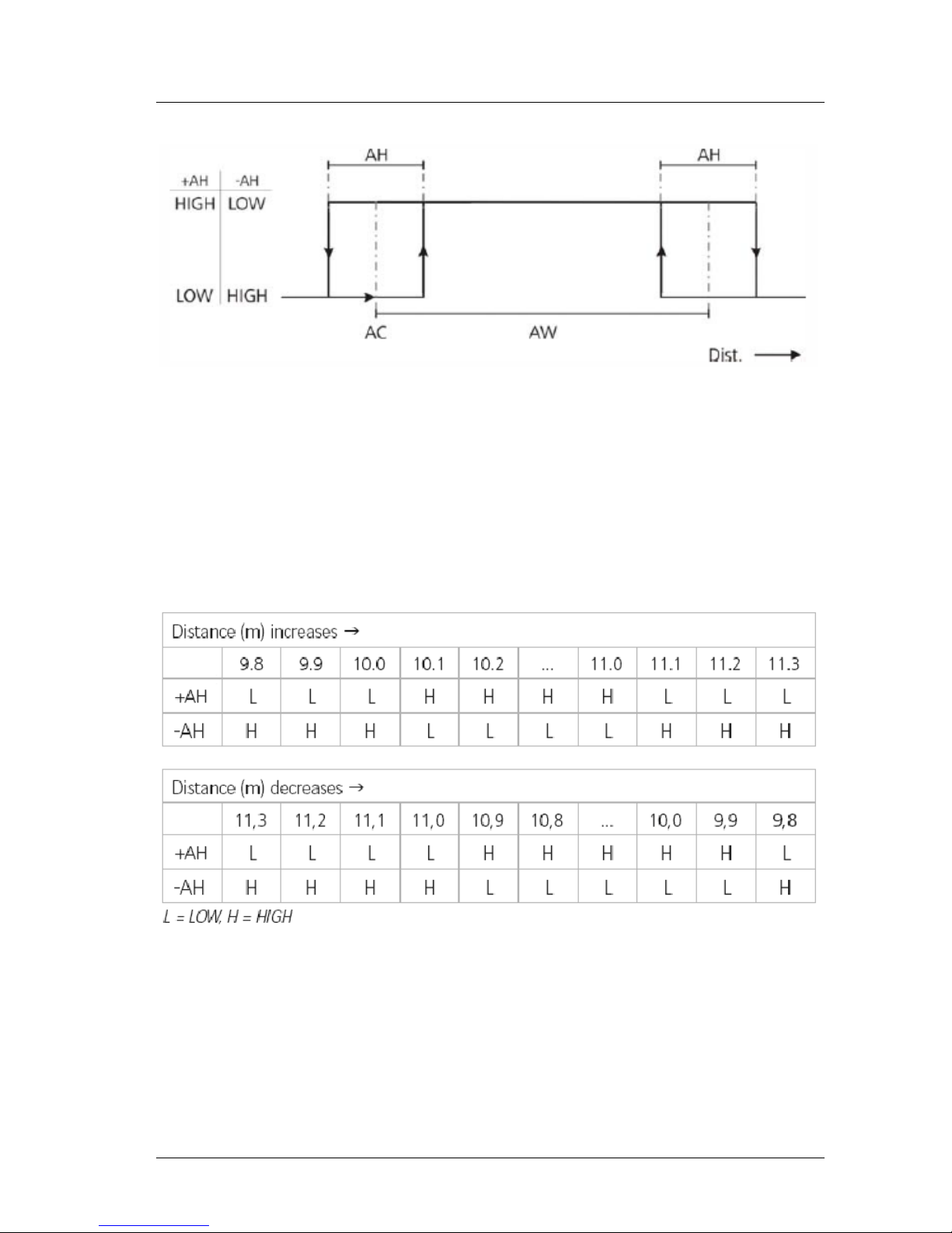
With the help of a user-selectable distance threshold, the switching output
can be set to monitor objects or conditions for positive or negative overstep.
For example, using the digital switching output, an object which was selected
for measurement can be monitored for excision of a threshold value. To do
this, parameter settings for a measurement window are required. Settings for
this window can be made via the three parameters: Alarm Center (AC), Alarm
Hysteresis (AH) and Alarm Width. The range which will be subject to
monitoring begins at AC and ends at AC+AW. Switching transitions can be set
via parameter AH.
The logic state of the switching output follows from the mathematical sign of
AH.
In the case of a positive AH, the output switches
- with increasing distance:
from LOW to HIGH if the distance is greater than (AC ±AH/2)
from HIGH to LOW if the distance is greater than (AC+AW+AH/2)
- with decreasing distance:
from LOW to HIGH if the distance is smaller than (AC +AW-AH/2)
from HIGH to LOW the distance is smaller than (AC-AH/2)
Page 41
LDM41E and LDM42E Manual Interface Connection
ASTECH GmbH Page 41
In the case of a negative AH, the output switching pattern will be inverse.
Figure 13 : Digital switching output behavior with positive and negative hysteresis
Example:
A moving object is assumed to be monitored within a window of 10 m to 11 m
with a hysteresis of 0.2 m.
AC10
AH0.2
AW1
How the switching output is to behave on occurrence of an error message
(E15, E16, E17, E18) can be defined by making suitable settings under “SE“
(see 8.13, SE – display/set error mode [0/1/2])
Page 42

Interface Connection LDM41E and LDM42E Manual
Page 42 ASTECH GmbH
9.5 Trigger Input
19
The trigger input is intended for triggering a distance measurement with an
external signal that is applied as a voltage pulse between 3 V and 20 V. This
input is used only in trigger mode DF (DF – distance measurement with
external trigger)!
It is for the user to specify a desired delay time and a pulse slope to be
selected for synchronization (see 8.20, TDx y – display/set trigger delay trigger
level). The distance measurement will always be started with a delay of 5 ms
in addition with the programmed trigger delay time.
Having done this, the LDM41E and LDM42E has to be switched to trigger
mode (see 8.6, DF – distance measurement with external trigger).
19
Trigger function is not available for devices with internal heating (option -h)
Page 43

LDM41E and LDM42E Manual List of Commands
ASTECH GmbH Page 43
10 List of Commands
Table 12 : Command list LDM41E and LDM42E
Command
Description
DT
Starts distance tracking
DS
Starts distance tracking (< 7 m)
DW
Starts distance tracking on white target at 10 Hz
DX
Starts distance tracking on white target at 50 Hz (only LDM
42E)
DF20
Starts remote-triggered single distance measurement
(single shot)
DM
Starts single distance measurement (single shot)
TP
Queries inner temperature
SA
Queries / sets floating average value (1...20)
SD
Queries / sets output format (dec/hex/sig)
ST
Queries / sets time to measure (0...25)
SF
Queries / sets scale factor
SE
Queries / sets error mode (0, 1, 2)
AC
Queries / sets alarm center
AH
Queries / sets alarm hysteresis
AW
Queries / sets alarm with
HO21
Queries / sets temperature for heating on
HF21
Queries / sets temperature for heating off
RM
Queries / sets removal measurement parameters
TD
Queries / sets trigger delay and level
TM
Queries / sets trigger mode and level
BR
Queries / sets baud rate
AS
Queries / sets auto start
OF
Queries / sets offset
SO
Sets current distance as offset
20
Trigger function is not available for devices with internal heating (option -h)
21
Only for devices with internal heating (option -h)
Page 44

List of Commands LDM41E and LDM42E Manual
Page 44 ASTECH GmbH
Command
Description
LO
Turns Laser on (do not use, please use DT)
LF
Turns Laser off
PA
Displays all parameter values
PR
Resets all parameters to standard values (don’t use)
Page 45

LDM41E and LDM42E Manual Error Codes
ASTECH GmbH Page 45
11 Error Codes
Table 13 : Error codes
Code
Description
Action
E15
Reflexes are too weak, or distance
from LDM (front edge) to target is
less than 0.1 m
Use white target board22 or
increase distance to target
E16
Reflexes are too strong
Use white target board or
filter
E17
Too much steady light (e.g. sun) or
reflexes are too strong
Use aperture or filter or
white target board
E18
DX mode (only LDM42E): reflexes
too weak, or distance from LDM
(front edge) to target is less than
0.1 m
Use white target board or
increase distance to target
E19
DX mode (only LDM42E):
Target motion speed > 10 m/s
Reduce motion speed
E23
Inner temperature below – 10°C
Heading necessary
E24
Inner temperature above + 60°C
Cooling necessary
E31
EEPROM checksum error
Necessary to repair
E51
Failed to set avalanche voltage
Necessary to repair
E52
Excessively high Laser current /
Laser defect
Necessary to repair
E53
Division by 0
SF must be unequal of zero
or necessary to repair
E54
Hardware error, PLL range
Necessary to repair
E55
Other hardware error
Necessary to repair
E61
Invalid command
Correct input
E62
Wrong parameter, wrong
command
Check data transmission
E63
SIO overflow
Check data transmission
E64
SIO framing error
Check data transmission
22
e.g. 3M, self adhesive foil matte white
Page 46

EG Declaration of Conformity LDM41E and LDM42E Manual
Page 46 ASTECH GmbH
12 EG Declaration of Conformity
In accordance with the
Directive of Electromagnetic Compatibility 2004/108/EG
The company ASTECH Angewandte Sensortechnik GmbH in Schonenfahrerstr.
5, 18057 Rostock / Germany herewith declare, represented by the signatory,
that the following designated product
Laser Distance Measurement Sensor
LDM41E / LDM42E
agrees with the following harmonized standard:
IEC 61326-1
Electromagnetic interference and electromagnetic compatibility (EMC)
*including radio interference
Rostock, 21. September 2010
ASTECH Angewandte Sensortechnik GmbH
Jens Mirow
General Manager
Page 47

LDM41E and LDM42E Manual Part Numbers
ASTECH GmbH Page 47
13 Part Numbers
Table 14 : Part numbers
Part-No.
Name
10-2028-00
LDM41E
10-2029-00
LDM42E
10-2036-00
LDM41E-h with heating
10-2037-00
LDM42E-h with heating
15-0040-00
Connection cable Ethernet M12 - RJ45, 3m
15-0040-01
Connection cable Ethernet M12 - RJ45, 5m
15-0040-02
Connection cable Ethernet M12 - RJ45, 10m
15-0011-00
Female cable connector Power and I/O, 5-pin A-coded
15-2002-00
CC4xPE 5 ,Connection cable Power and I/O, 5m
15-2002-01
CC4xPE-10, Connection cable Power and I/O, 10m
15-0019-00
PC-Programming cable RS232, 5m
11-0001-00
USB-RS232 Interface converter, 0.2m
12-2006-00
PW4-S-10, Protection window Standard for LDM4x-Series
12-2030-00
GFW2-10, Grey filter 2-fach for LDM4x-Series
12-2030-01
GFW4-10, Grey filter 4-fach for LDM4x-Series
12-2010-00
ARF-w, Reflection foil matte/white, A4
12-2011-00
ARF-s, Highly reflective foil silver, A4
12-2015-00
PT4x-AIR, Protection tube for pressure air for LDM4x-Series
11-0006-00
ASTECH USB Stick (Documentation and Software)
16-2004-01
Printed Manual LDM41E and LDM42E, A5, DE
16-2004-02
Printed Manual LDM41E and LDM42E, A5, EN
17-2000-00
License number for PC-Software LDMTOOL for LDM3x und
LDM4x
Note: Several single sensors are also available as packages including sensor
and cable, manual and CD (sets). Additionally are other protection enclosures
with and without a thermostat available.
Page 48

Notice LDM41E and LDM42E Manual
Page 48 ASTECH GmbH
 Loading...