

Page 1
1
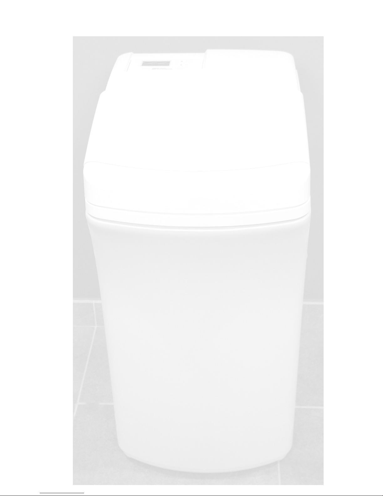
A-Star
Premium
Water softening system
Installation
Programming
Troubleshooting
Version 05-2006
Page 2

2
SAFETY GUIDES
• FOLLOW THE INSTALLATION INSTRUCTIONS CAREFULLY. FAILURE TO INSTALL THE
SOFTENER PROPERLY VOIDS THE WARRANTY.
• BEFORE YOU BEGIN INSTALLATION, READ THIS ENTIRE MANUAL. THEN, OBTAIN ALL
THE MATERIALS AND TOOLS YOU WILL NEED TO MAKE THE INSTALLATION.
• CHECK LOCAL PLUMBING AND ELECTRICAL CODES. THE INSTALLATION MUST
CONFORM TO THEM. IF IN DOUBT, CONTACT YOUR LOCAL DEALER OUR PLUMBER.
• USE ONLY LEAD-FREE SOLDER AND FLUX FOR ALL SWEAT-SOLDER CONNECTIONS,
AS REQUIRED BY YOUR COUNTRY CODES.
• USE CARE WHEN HANDLING THE SOFTENER. DO NOT TURN UPSIDE DOWN, DROP,
OR SET ON SHARP PROTRUSIONS.
• DO NOT LOCATE THE SOFTENER WHERE FREEZING TEMPERATURES OCCUR. DO
NOT ATTEMPT TO TREAT WATER OVER 49°C. FREEZING, OR HOT WATER DAMAGE
VOIDS THE WARRANTY.
• AVOID INSTALLING IN DIRECT SUNLIGHT. EXCESSIVE SUN HEAT MAY CAUSE
DISTORTION OR OTHER DAMAGE TO NON-METALLIC PARTS.
• THE SOFTENER IS NOT DISINGED FOR OUTSIDE INSTALLATION; IF INSTALLING IN AN
OUTSIDE LOCATION, YOU MUST TAKE THE STEPS NECESSARY TO ASSURE THE
SOFTENER, INSTALLATION PLUMBING, WIRING, ETC; ARE AS WELL PROTECTED
FROM THE ELEMENTS (SUNLIGHT, RAIN, WIND, HEAT, COLD), CONTAMINATION,
VANDALISM, ANIMALS, RODENDS, ETC AS WHEN INSTALLED INDOORS;
• THE SOFTENER REQUIRES A MINIMUM WATER FLOW OF 11 LITERS PERMINUTE AT
THE INLET. MAXIMUM ALLOWABLE INLET WATER PRESSURE IS 8.5 BAR. IF DAYTIME
PRESSURE IS OVER 5.6 BAR, NIGHTTIME PRESSURE MAY EXCEED THE MAXIMUM.
USE A PRESSURE REDUCING VALVE IF NECESSARY. (ADDING A PRESSURE
REDUCING VALVE MAY REDUCE THE FLOW.)
• THE SOFTENER WORKS ON 24 VOLT-50 Hz ELECTRICAL POWER ONLY. BE SURE TO
USE THE INCLUDED TRANSFORMER, AND PLUG IT INTO A NOMINAL 220V, 50 CYCLE
HOUSEHOLD OUTLET THAT IS GROUNDED AND PROPERLY PROTECTED BY A
OVERCURRENT DEVICE SUCH AS A CIRCUIT BREAKER OR FUSE. IF TRANSFORMER
IS REPLACED, USE ONLY THE AUTHORIZED SERVICE CLASS II, 24 VOLT
TRANSFORMER. THIS SOFTENER IS NOT INTENDED TO BE USED FOR TREATING
WATER THAT IS MICROBIOLOGICALLY UNSAFE OR OF UNKNOWN QUALITY WITHOUT
ADEQUATE DISINFECTION BEFORE OR AFTER THE SOFTENER.
RECYCLE
European Directive 2002/96/EC requires all electrical and electronic equipment to be disposed
of according to Waste Electrical and Electronic Equipment (WEEE) requirements. This
directive or similar laws are in place nationally and can vary from region to region. Please
refer to your state and local laws for proper disposal of this equipment.
Page 3

3
UNPACKING / INSPECTION
The softener is shipped in one master carton. The softeners are completely assembled
at the factory, except as required at installation. Be sure to check the entire softener for
any shipping damage or parts loss. Also note damage to the shipping cartons. Contact
the transportation company for all damage and loss claims. The manufacturer is not
responsible for damages in transit. Small parts, needed to install the softener, are in
parts bag. To avoid loss of the small parts, keep them in the parts bag until you are
ready to use them.
TABLE OF CONTENTS
PAGE N°
SAFETY GUIDES 2
SPECIFICATIONS, DIMENSIONS 4
BEFORE STARTING INSTALLATION 5 - 6
TYPICAL INSTALLATION ILLUSTRATION 6
INSTALLATION STEPS 7- 10
PROGRAMMING THE TIMER 11 - 13
SANITIZING PROCEDURES 14
WATER AND WATER CONDITIONING 15 - 16
HOW THE WATER SOFTENER WORKS 16 - 17
GENERAL WATER SOFTENER MAINTENANCE & TROUBLESHOOTING 18 - 20
AUTOMATIC ELECTRONIC DIAGNOSTICS 20
SERVICE CHECKOUT PROCEDURES, WIRING SCHEMATIC 21 - 23
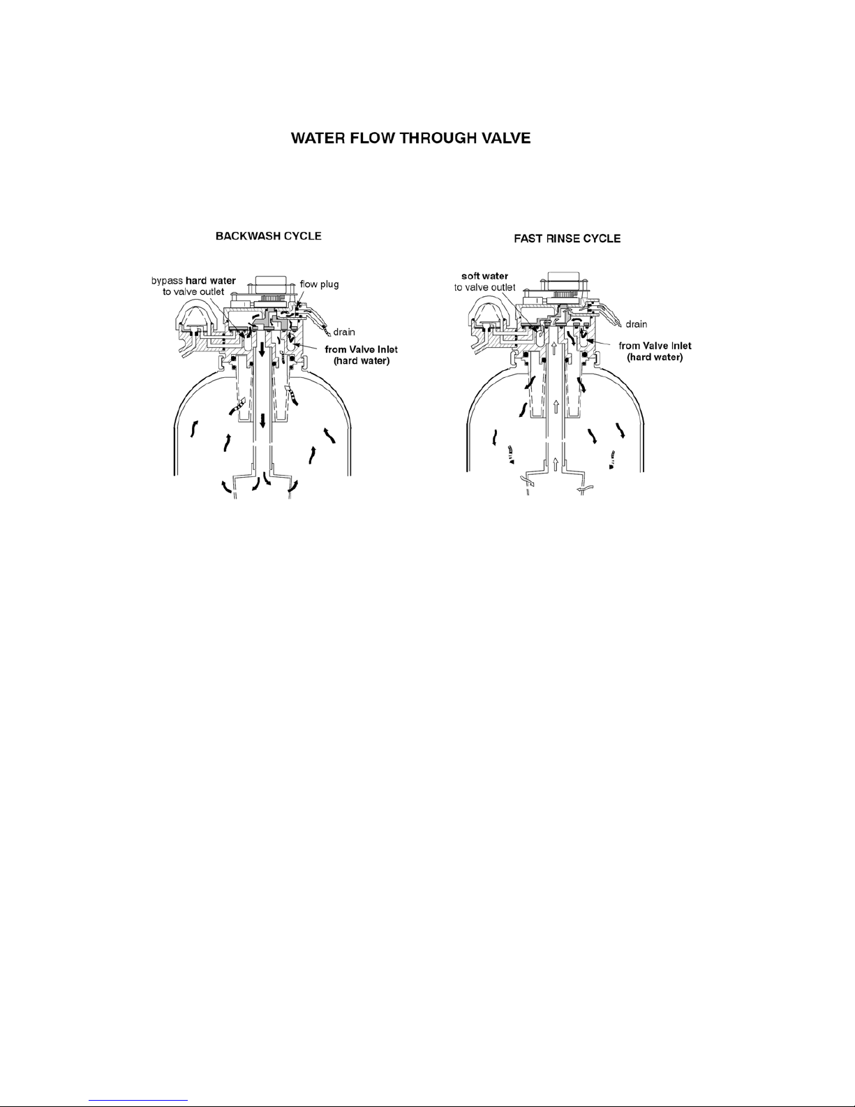
WATER FLOW THROUGH VALVE 24 - 25
REPAIR PARTS 26 - 30
Page 4
4
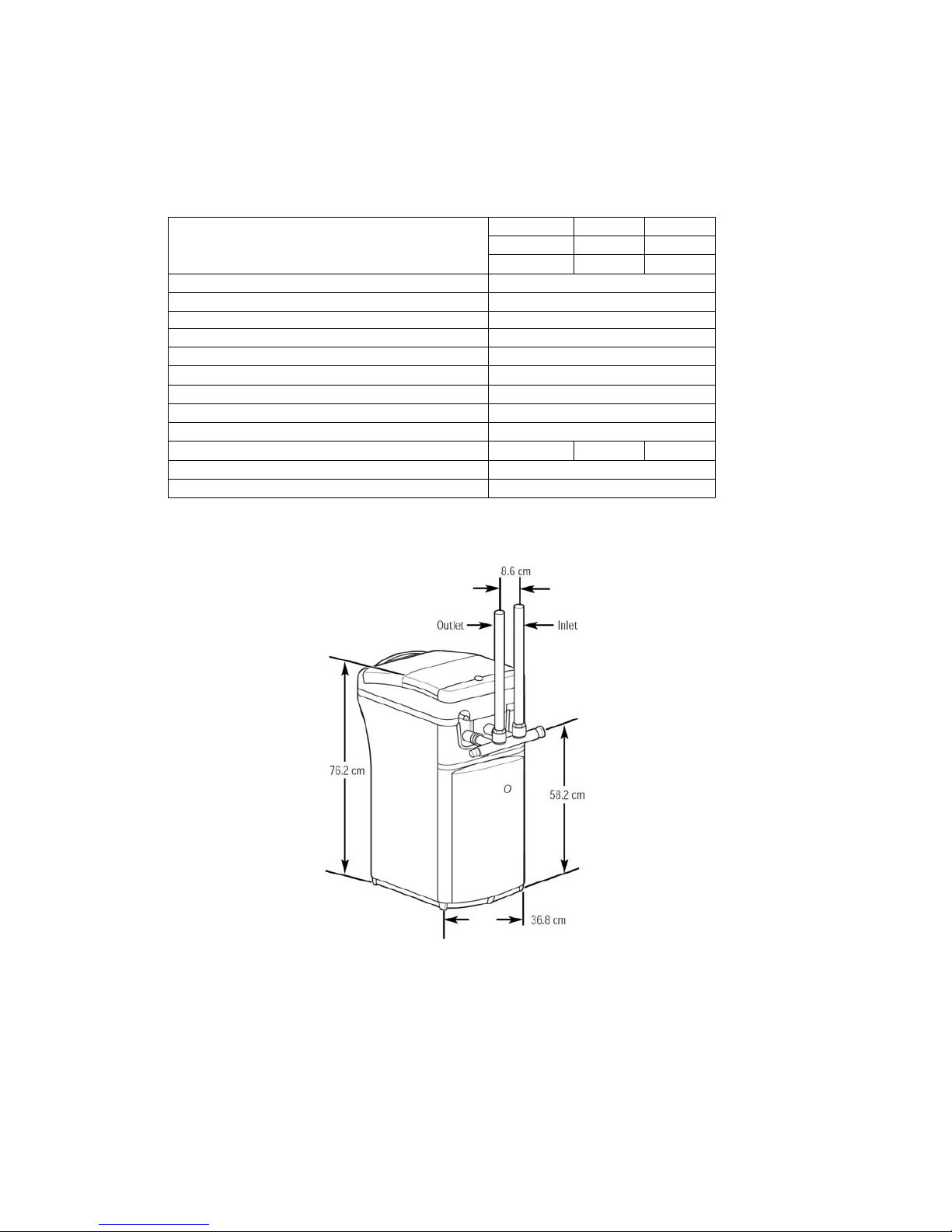
SPECIFICATIONS AND DIMENSIONS
52 @ 0.8
86 @ 1.7
Rated Capacities @ salt dose (°Fm³@Kg)
122 @ 4.6
Resin Quantity (Liters) 18
Rated Service Flow (L/min) 26
pressure drop @ service flow (BAR) 0.6
Max Flow rate to the drain (l/min) 11
Max hardness (°F) 162
Max Clear water Iron ( PPM) 5
Tank Size ( inch) 10*21
Valve connections (inch) 3/4
Capacity salt tank (Kg) 45
Operating water pressure limits (Bar)) 1.4 to 8.6
Operating Water temp limits (°C) 4-49
electrical rating Transformer 240 VAC to 24 V AC
Page 5

5
BEFORE STARTING INSTALLATION
WHERE TO INSTALL THE SOFTENER
o Place the softener as close as possible to the pressure tank (well system) or
water meter (city water).
o Place the softener as close as possible to a floor drain, or other acceptable drain
point (laundry tub, sump, standpipe, etc.).
o Connect the softener to the main water supply pipe BEFORE or AHEAD OF the
water heater. DO NOT RUN HOT WATER THROUGH THE SOFTENER.
Temperature of water passing through the softener must be less than 49°C
(120°F).
o Keep outside faucets on hard water to save soft water and salt.
o Do not install the softener in a place where it could freeze. Damage caused by
freezing is not covered by the warranty.
o Put the softener in a place water damage is least likely to occur if a leak
develops. The manufacturer will not repair or pay for water damage.
o A 220 volt 50 Hz electric outlet, to plug the included transformer into, is needed
within 2 meters of the softener. The transformer has a 2 meters power cable. Be
sure the electric outlet and transformer are in an inside location, to protect
from wet weather.
o If installing in an outside location, you must take the steps necessary to assure
the softener, installation plumbing, wiring, etc., are as well protected from the
elements, contamination, vandalism, animals, rodents etc., as when installed
indoors.
o Keep the softener out of direct sunlight. The sun’s heat will melt plastic parts.
TOOLS, PIPE and FITTINGS, OTHER MATERIALS YOU WILL NEED
o In and out pipes to the softener must be at least 3/4” size. Some local codes
require a minimum of 1” pipe size. To plumb with 1” pipes, buy adaptors to fit the
1” pipe threads on the installation adaptors or bypass valve (see page 5). You
should maintain the same, or larger, pipe size as the water supply pipe, up to the
softener inlet and outlet.
o Use copper, brass, or galvanized pipe and fittings. Some codes may also allow
CPVC plastic pipe.
o ALWAYS install a bypass valve or valves. Either use the optional valve (included
with some models), or 3 shut-off valves. Bypass valves let you turn off water to
the softener for repairs if needed, but still have water in the house pipes.
o Drain hose (3/8” or 7/16” inside diameter) is needed for valve and salt tank
drains. You can buy good quality, thick-wall, flexible hose at most hardware
stores.
o If a rigid valve drain is needed, to comply with plumbing codes, you can buy the
parts needed (see page 8) to connect a 1/2 in. copper tubing drain.
o Nugget or pellet water softener salt is needed to fill the brine tank (see page 10
and 118).
Page 6
6
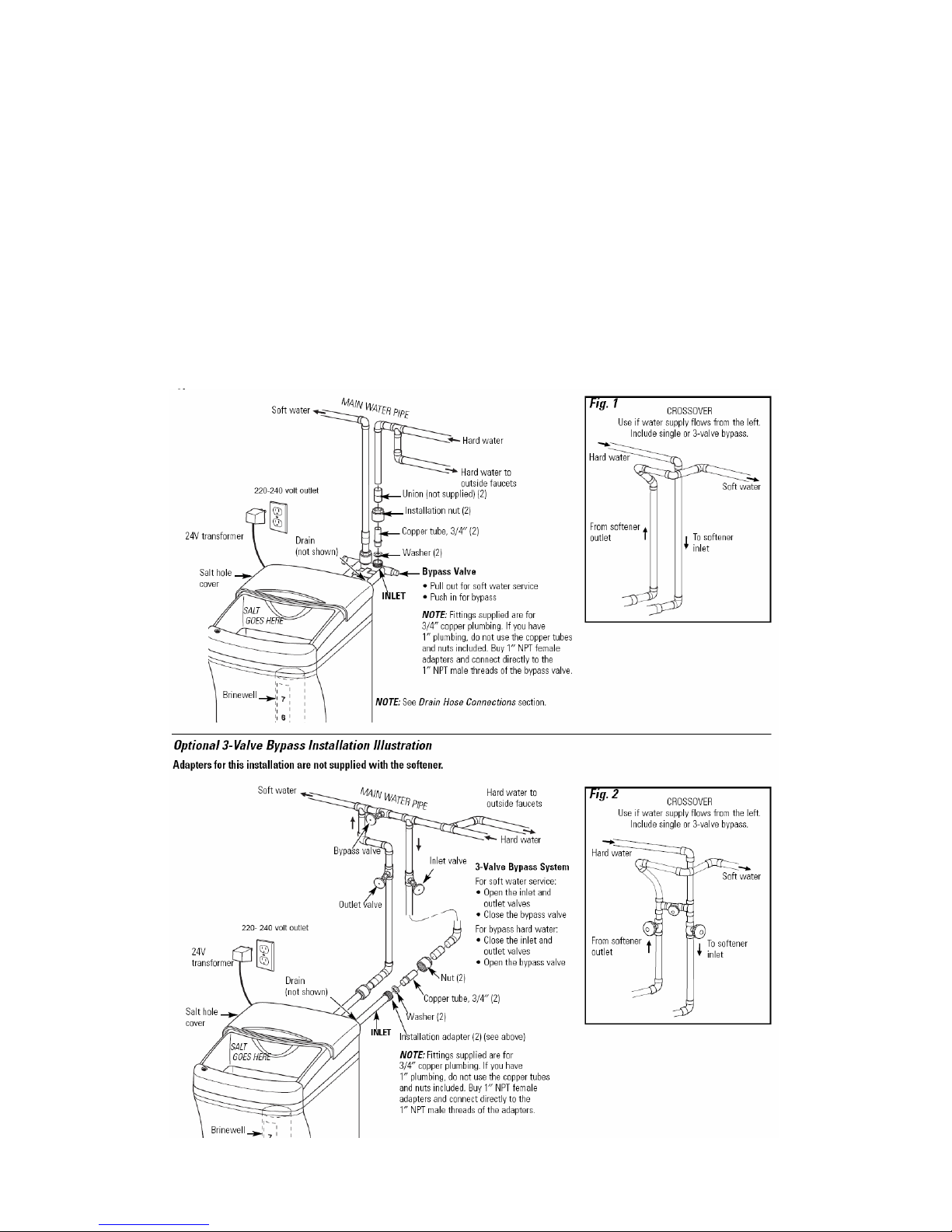
PLAN HOW YOU WILL INSTALL THE SOFTENER
You must first decide how to run in and out pipes to the softener. Look at the house main
water pipe at the point where you will connect the softener. Is the pipe soldered copper,
glued plastic, or threaded galvanized? What is the pipe size? Now look at the typical
installation illustration below. Use it as a guide when planning your particular installation.
Be sure to direct raw, hard water to the softener valve inlet fitting.
The valve is marked IN and OUT.
Typical Installation Illustration
Page 7
7
INSTALLATION STEPS
NOTE:
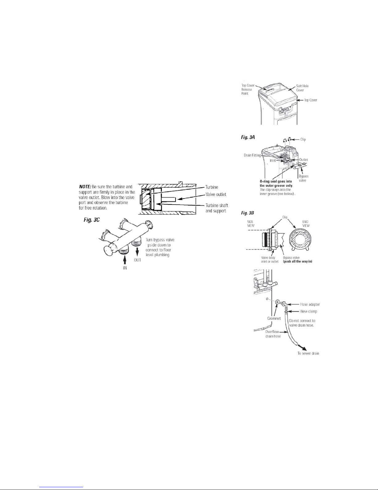
For easier installation, remove the top cover
cover forward and lift up.
1. INSTALL BYPASS VALVE:
o Remove the plastic shipping plug and wire from valve outlet.
o Push the bypass valve (lubricate o--ring seals)into
both ports of the valve...Figures 3A.
o Snap the two large plastic clips in place, from the
top, down...Figures 3A and 3B. Be sure they snap
into place. Pull on the adaptors, or bypass valve,
to make sure they held securely in place.
2. INSTALL THE BRINE TANK OVERFLOW FITTINGS:
o Insert the rubber grommet into the 3/4” diameter
hole in the brine tank sidewall...see page 9.
o Push the barbed end of the hose adaptor elbow
into the grommet.
3. MOVE THE SOFTENER ASSEMBLY INTO INSTALLATION POSITION:
o Be sure the installation surface is level and smooth. If needed, place the tank on
a section of 2 cm thick (min.) plywood. Then, place shims under the plywood as
needed to level the softener.
Page 8

8
4. INSTALL GROUNDING CLAMPS AND WIRE (Recommended):
o To maintain electrical ground continuity in the
house cold water piping, install the ground clamps
(not included) as shown. Be sure the pipes are clean,
under the clamps, to assure good contact.
NOTE: A 3-valve bypass system maintains ground
continuity.
5. PLUMB IN AND OUT PIPES TO AND FROM SOFTENER:
CAUTION: Observe all of the following cautions as you connect inlet and outlet
plumbing.
o Turn off the house water supply valve and open faucets to relieve pressure
in the pipes.
o BE SURE RAW,
HARD WATER IS DIRECTED TO THE VALVE INLET
PORT.
o Be sure to use bypass valve(s).
o If making a soldered copper installation, do all sweat soldering before
connecting pipes to the softener fittings. Torch heat will damage plastic parts.
o Put grounding clamps (see step 4) on copper tubes before soldering.
o When turning threaded pipe fittings onto plastic fittings, use care not to cross-
thread.
o Use pipe joint compound on all external pipe threads.
o Support inlet and outlet plumbing in some manner (use pipe hangers) to keep the
weight off of the valve fittings.
6. CONNECT AND RUN THE VALVE DRAIN HOSE: (figure 4)
o Take a length of 3/8” or 7/16” inside diameter hose and attach to the valve
drain fitting. So water pressure does not blow the hose off, use a hose clamp
to secure in place.
o Locate the other end of the hose at a suitable drain point...floor drain, sump,
laundry tub, etc. Check and comply with local codes.
IMPORTANT: Use high quality, thick-wall hose that will not easily kink or collapse.
The water softener will not work if water cannot exit this hose during regenerations.
o Tie or wire the hose in place at the drain point.
Water pressure will cause it to whip during the
backwash and fast rinse cycles of regeneration.
Also provide an air gap of at least 4 cm between
the end of the hose and the drain point.
An air gap prevents possible siphoning of sewer
water, into the softener, if the sewer should ‘‘back-up’’.
Page 9
9
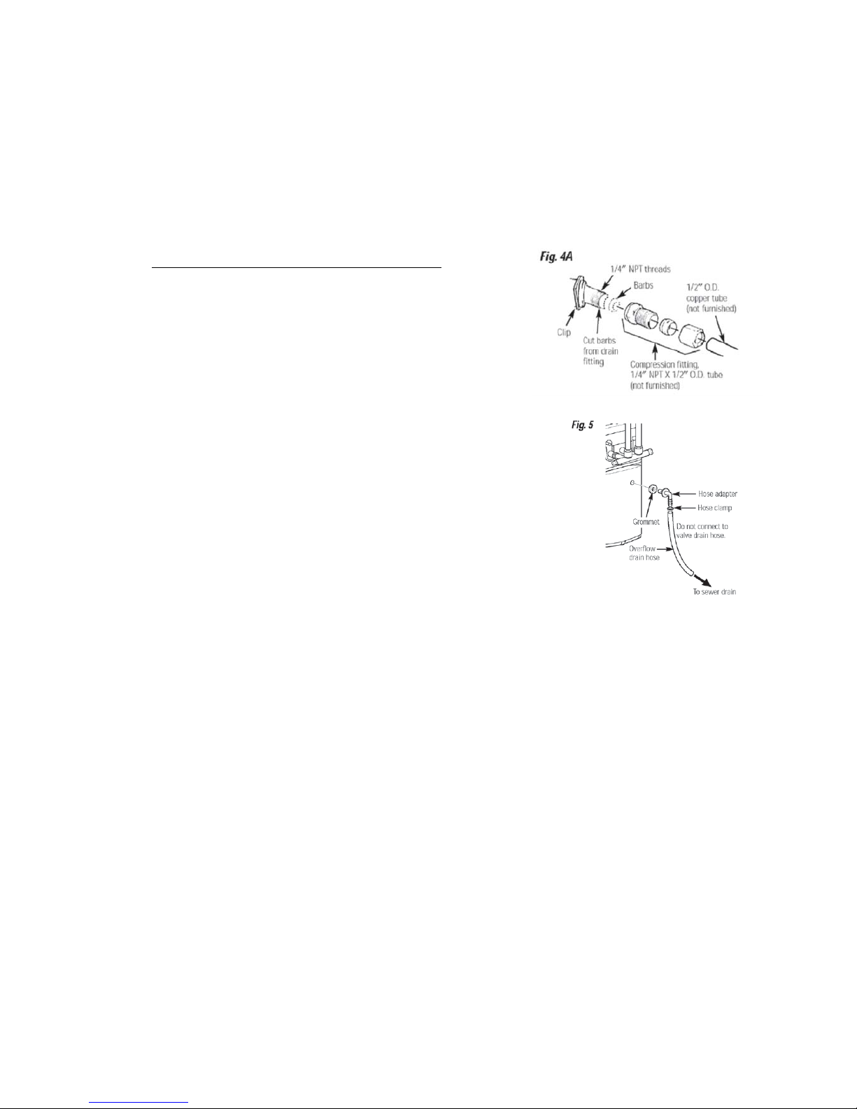
o If raising the drain hose overhead is required to
get to the drain point, do not raise higher than
2.4 meters above the floor. Elevating the hose
may cause a back-pressure that could reduce brine
draw during regenerations.
CONNECTING A RIGID VALVE DRAIN TUBE
o To adapt a copper drain tube to the softener,
use a hacksaw to cut the barbed end from the
drain fitting as shown in Fig. 4A. Rotate the drain
fitting so the cutting blade clears the valve housing
to prevent damage to valve. Buy a compression
fitting (1/4″ female pipe thread x 1/2″ O.D. tube)
and needed tubing from your local hardware store.
7. CONNECT AND RUN THE BRINE TANK OVERFLOW HOSE :
o Attach a length of 3/8” or 7/16” I.D. hose to the
drain elbow, installed in step 2, page 7. Use a
hose clamp to hold it in place.
o Locate the other end of the hose at the drain point.
DO NOT ELEVATE THIS HOSE HIGHER THAN
THE ELBOW ON THE BRINE TANK. DO NOT TEE
THIS HOSE TO THE VALVE DRAIN HOSE.
NOTE: This drain is for safety only. If the brine tank should over-fill
with water, the excess is carried to the drain.
8. FLUSH PIPES, EXPEL AIR FROM SOFTENER, AND TEST YOUR
INSTALLATION FOR WATER LEAKS:
CAUTION: To avoid water or air pressure damage to softener inner parts, be sure
to do the following steps exactly as listed.
A. Fully open two cold, soft water faucets nearby the softener.
B. Place bypass valve(s) in ‘‘bypass’’ position. On a single valve, slide the stem into
BYPASS. On a 3-valve system, close the inlet and outlet valves,
and open the bypass valve...see page 6.
C. Fully open the house main water pipe shutoff valve. Observe a steady flow from both
opened faucets.
D. Place bypass valve(s) in ‘‘service”, EXACTLY as follows. KEEP SOFTWATER
FAUCETS OPEN.
1. SINGLE BYPASS VALVE: SLOWLY, slide the valve stem toward ‘‘service’’, pausing
several times to allow the softener to pressurize slowly.
2. 3--VALVE BYPASS: Fully close the bypass valve and open the outlet valve.
SLOWLY, open the inlet valve, pausing several times to allow the softener to pressurize
slowly.
E. After about three minutes, open a HOT water faucet for one minute, or until all air
is expelled, then close.
F. Close both cold water faucets.
Page 10

10
G. Check your plumbing work for leaks and fix right away, if any are found. BE SURE
TO OBSERVE PREVIOUS CAUTION NOTES.
H. Turn on the gas or electric supply to the water heater. Light the pilot, if applicable.
9. ADD WATER AND SALT TO THE BRINE TANK:
o Slide open the salt storage area cover. Add about 10 liters of water into the tank.
DO NOT ADD INTO THE BRINEWELL.
o *Fill the tank with NUGGET, PELLET or coarse SOLAR water softener salt. Do
not use rock, block, granulated, and ice cream making salts, or salt with iron
removing additives. Salt storage capacity 45 Kg.
*Note: If the softener is installed in a humid basement or other damp area, it is better to
fill the tank more often using less salt (see salt bridging in the maintenance section). The
salt will last for several months, depending on water hardness, family size.
10. CONNECT TO ELECTRICAL POWER:
o The softener works on 24 volt, 50Hz electric power. The included transformer
changes standard 220 volt AC house power to 24 volts. Plug the transformer
into a 220 volt outlet only. Be sure the outlet is always ‘‘live’’ so it can not be
switched off by mistake. Plug the transformer into the electrical outlet.
11. PROGRAM THE TIMER: "ELECTRONIC DEMAND TIMER...(See pages 11-
13)
Page 11
11
PROGRAM THE TIMER: "ELECTRONIC DEMAND TIMER
CONTROL SETTINGS REQUIRED UPON INSTALLATION.
NOTES:
o When the transformer is plugged in, the model code F 18 shows in the face plate
display for a few seconds. The model code is then followed by a test number
(example: J1.1). After the test number, 12:00 PM and the words “PRESENT
TIME” begin to flash in the display.
o If ---- is flashing, use the UP ▲ button to set the code to F18. If you pass by the
correct code number, use the DOWN ▼ button. Then press the SELECT button
to accept the correct model.
o A “beep” sounds while pressing buttons for control programming. One beep
signals a change in the control display. Repeated beeps mean the control will not
accept a change from the button you have pressed, and you should select
another button.
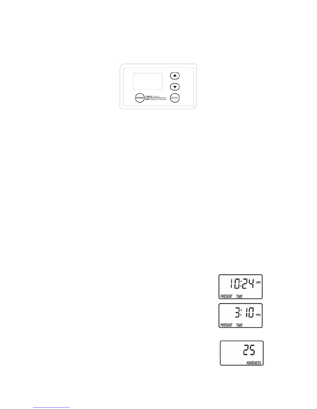
o To program the control, you will use the UP ▲, DOWN ▼ and SELECT buttons.
PROGRAM MEMORY:
If electrical power to the softener is interrupted, the time display is blank, but the timer
keeps correct time for about 6 hours. When power is restored, you have to reset the
present time only if the display is flashing. All other settings are maintained and never
require resetting unless a change is desired.
SET PRESENT TIME OF DAY
1. Press the SELECT button until a flashing 12:00 PM and the words “PRESENT
TIME” are shown in the display.
2. Press UP ▲or DOWN ▼ button to set. The UP ▲ button
advances the time; the DOWN ▼button moves the time
in reverse. If the present time is between noon and
midnight, be sure PM shows in the display. If the
present time is between midnight and noon, be sure
AM shows in the display.
NOTE: Each press of an UP ▲ or DOWN ▼ button
changes the time by one minute. Holding the button
changes the time at a rapid rate.
3. When the present time is correct, press SELECT to accept.
SET WATER HARDNESS NUMBER
1. Press the SELECT button a flashing 25 and the word
“HARDNESS” are shown in the display.
2. Press UP ▲ or DOWN ▼ button to set your water
Page 12
12
hardness number in the display. DOWN ▼decreases the hardness value. UP
▲ increases the hardness value.
NOTE: Each press of a button changes the display by 1, between 1 and 25.
Above 25, the display changes 5 at a time (25, 30, 35, etc.). Holding a
button in changes the numbers at a rapid rate.
3. When the display shows your water hardness (in grains per gallon), press
SELECT to accept.
NOTE: If there is clear water iron in your water supply, you will need to
increase the hardness setting by 5 for each 1 ppm of clear water iron in your
water supply. You can get the grains per gallon (gpg) hardness of your water
supply from a water analysis laboratory. If you are on a municipal supply, call
your local water department. Or your local dealer to request a water hardness
test kit.
If your report shows hardness in parts per million (ppm) or milligrams per liter
(mg/l), simply divide by 17.1 to get the equivalent number of grains per gallon. To
convert to other hardness indications use the following conversion: 1gpg = 0.959
°dH = 1.71 °fH = 171 ppm.
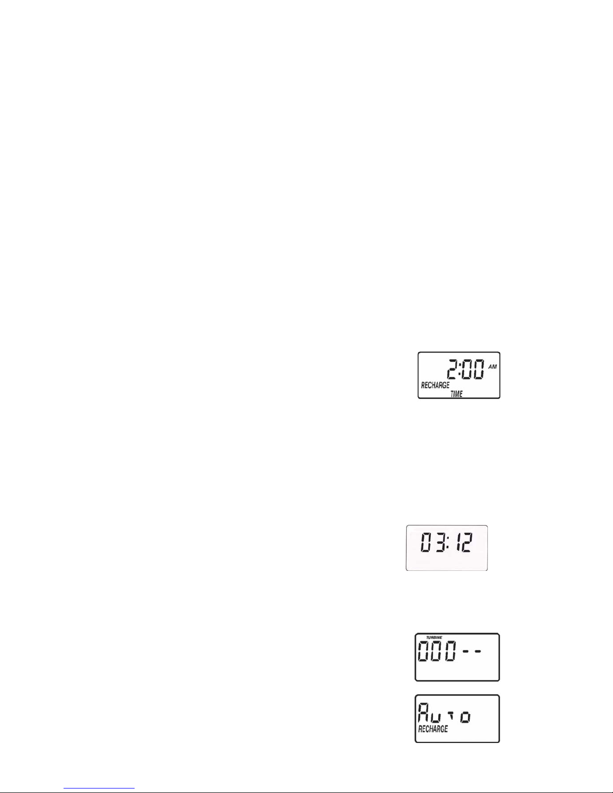
SET RECHARGE (STARTING) TIME
1. Press the SELECT button a flashing 2:00 AM and the words “RECHARGE
TIME” show in the display.
NOTE: The 2:00 AM (factory default) is a good time for
recharge to start (takes about 2 hours) in most
households because water is not in use.
HARD WATER is bypassed to house faucets during
recharge. If no change is needed, go to step 3.
To change the recharge starting time, follow step 2.
2. Press UP ▲ or DOWN ▼ button to set the desired recharge start time. Be
sure to observe the AM or PM as you did when setting the time of day.
NOTE: Each press of a button changes the time by 1 hour. Holding the buttons
in changes the time at a rapid rate.
3. Press the SELECT button to accept.
ELECTRONIC DEMAND TIMER FEATURES
NORMAL OPERATION, TIMER DISPLAYS
During normal operation, the present time of day
shows in the time display area.
SET MAX DAYS BETWEEN RECHARGES
The default setting allows the timer to control regeneration frequency based on water
usage readings from the water meter. It provides the most economical operation. You
can set a maximum time (in days) between regenerations. For example, no more than 3
days will pass without a regeneration occurring if you set “3 day" in the display. The
available settings are 1 to 15 days.
1. Press and hold the SELECT button until the display
shows 000 - -.
2. Press the SELECT button once more to display the
Max Days Between Recharges screen. The
Page 13
13
default setting is “Auto”.
3. Press UP ▲ or DOWN ▼ buttons to change the setting.
Press the SELECT button to set.
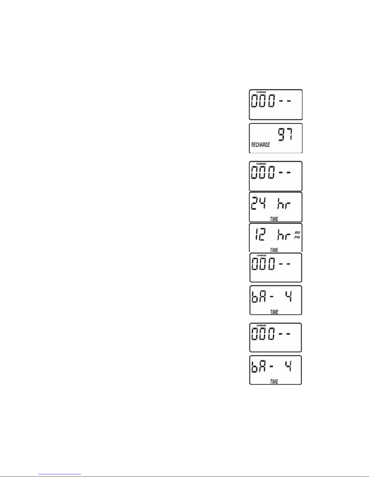
SET 97% FEATURE
By setting this feature to On, the unit will automatically recharge
when 97% capacity has been used, at any time of day.
1. Press and hold the SELECT button until the
display shows 000 - -.
2. Press the SELECT button twice to display the 97%
Feature screen. The default setting is “OFF”.
3. Press UP or DOWN buttons to change the setting.
Press the SELECT button to set.
SET 12 / 24 HOUR CLOCK
You can change clock display from 12 hour (AM & PM) or 24 hour
format.
1. Press and hold the SELECT button until the display shows
000 - -.
2. Press the SELECT button three times to display the Set
12 / 24 Hour Clock screen. The default setting is 24 Hour.
NOTE: If 12 Hour clock is selected, be sure to observe
AM or PM when setting the time.
3. Press UP or DOWN buttons to change the setting.
Press the SELECT button to set.
SET ADJUSTABLE BACKWASH TIME
The timer can be changed to allow a different backwash time,
if so desired. The default setting is 4 minutes.
This can be adjusted from 1 to 60 minutes.
1. Press and hold the SELECT button until the display
shows 000 - -.
2. Press the SELECT button four times to display
“bA- 4”.
3. Use the UP ▲ or DOWN ▼ buttons to set the number of
minutes desired for backwash. Press the SELECT button to set.
SET ADJUSTABLE FAST RINSE TIME
The timer can be changed to allow a different fast
rinse time, if so desired. The default setting is 2
minutes. This can be adjusted from 1 to 60 minutes.
1. Press and hold the SELECT button until the display
shows 000 - -.
2. Press the SELECT button five times to display “Fr- 2”.
3. Use the UP ▲ or DOWN ▼ buttons to set the number of
minutes desired for fast rinse. Press the SELECT button to set.
Page 14

14
SANITIZING PROCEDURES
Care is taken at the factory to keep your water softener clean and sanitary. Materials
used to make the softener will not infect or contaminate your water supply, and will not
cause bacteria to form or grow. However, during shipping, storage, installing and
operating, bacteria could get into the softener. For this reason, sanitizing as follows is
suggested when installing.
1. Be sure to complete all installation steps, including timer programming.
2. Pour about 22 ml of common 5.25% household bleach (Clorox, Linco, Bo Peep,
White Sail, Eagle, etc.,) into the brine well.
3. Use the RECHARGE NOW feature, on the timer, to start an immediate regeneration.
The bleach is drawn into and through the water softener to sanitize it. This sanitizing
regeneration is over in about two hours. Then, soft water is available for your use.
NOTE: When the above sanitizing regeneration is over, all remaining bleach is
flushed from the conditioner and your house COLD water supply is fully soft
immediately. However, your water heater is filled with hard water and, as hot
water is used, it will refill with soft water. When all the hard water is replaced, in
the water heater, hot only, and mixed hot and cold water will be fully soft. If you
want totally soft water immediately, after the above regeneration, drain the water
heater until the water runs cold. If you do drain the water heater, use extreme
care as the water could cause severe burns.
Page 15

15
WATER AND WATER CONDITIONING
WATER
Man’s very existence depends on water. It is one of the basic commodities of life. Water
is best as nature provides it, is a common misconception. Practically all natural water
needs refinement or treatment to make it safe to drink or more satisfactory to use.
The earth’s water supply cycle starts in the upper cloud layers. As it falls to the earth as
rain or snow, it picks up impurities and gases from the atmosphere. Landing on earth, it
seeps over and through the ground, dissolving earth minerals. Passing through
limestone, it dissolves calcium and magnesium, the hardness minerals. Iron deposits
impart iron to the water. Acidity and sediments are other water conditions. Municipal
water supplies come from surface reservoirs, such as lakes and rivers, or from
underground reservoirs. Usually, municipalities chlorinate the water to make it safe to
drink. Sediment is removed by filtration. Tastes and odors are reduced or eliminated.
The water is conditioned to comply with certain specifications. However, hardness
minerals, tastes and odors are not always reduced to the most desirable levels.
Underground reservoirs provide our private water supplies. Because the water is raw
and untreated, it can have varying amounts of hardness, iron, tastes, odors, acidity, or
combinations of these. Different localities and water levels affect mineral content.
WATER CONDITIONING
Water conditioning is the treatment of four general conditions. These are: Hardness,
Iron, Acidity, Sediments.
HARDNESS is a term to describe the presence of calcium and magnesium minerals in
water. A chemical analysis accurately measures the amount of minerals in grain weight.
For example, 4 liters of water with 8.5
°fH (= 4.8 °dH) hardness has dissolved minerals,
that if solidified, about equals the size of one ordinary aspirin tablet. Four liters of water,
43
°fH hard (= 24 °dH), has a mineral content equal in size to five aspirin tablets. Water
hardness varies greatly across the country. Hard water affects living in general.
Hardness minerals combine with soap to make a soap curd. The curd greatly reduces
the cleaning action of soap. Precipitated hardness minerals form a crust on
cooking utensils, appliances, and plumbing fixtures. Even the tastes of foods are
affected. A water softener removes the hardness minerals to eliminate these problems,
and others. Sodium Information: Water softeners using sodium chloride (salt) for
regeneration add sodium to the water. Persons on sodium restricted diets should
consider the added sodium as part of their overall intake.
IRON in water is measured in parts per million (ppm). The total* ppm of iron, and type or
types*, is determined by chemical analysis. Four different types of iron in water are
Ferrous (clear water), Ferric (red water), Bacterial and organically bound iron,
Colloidal
and inorganically bound iron (ferrous or ferric).
*
Water may contain one or more of the four types of iron and any combination of these. Total iron
is the sum of the contents.
o Ferrous (clear water) iron is soluble and dissolves in water. It is usually detected
by taking a sample of water in a clear bottle or glass. Immediately after taking,
the sample is clear. As the water sample stands, it gradually clouds and turns
slightly yellow or brown as air oxidizes the iron. This usually occurs in 15 to 30
minutes. A water softener will remove moderate amounts of this type of iron (see
specifications).
Page 16

16
o Ferric (red water), and Bacterial and organically bound irons are insoluble. This
iron is visible immediately when drawn from a faucet because it has oxidized
before reaching the home. It appears as small cloudy yellow, orange, or reddish
suspended particles. After the water stands for a period of time, the particles
settle to the bottom of the container. Generally these irons are removed from
water by filtration. Chlorination is also recommended for bacterial iron.
o Colloidal and inorganically bound iron is of ferric or ferrous form that will not filter
or exchange out of water. In some instances, treatment may improve colloidal
iron water, but always CONSULT AQUALIFIED WATER CHEMISTRY LAB
before attempting to treat it. Colloidal iron water usually has a yellow appearance
when drawn. After standing for several hours, the color persists and the iron does
not settle, but remains suspended in the water. Iron in water causes stains on
clothing and plumbing fixtures. It negatively affects the taste of food, drinking
water, and other beverages.
ACIDITY or acid water is caused by carbon dioxide, hydrogen sulfide, and sometimes
industrial wastes. It is corrosive to plumbing, plumbing fixtures, water heaters, and other
water using appliances. It can also damage and cause premature failure of seals,
diaphragms, etc., in water handling equipment. A chemical analysis is needed to
measure the degree of acidity in water. This is called the pH of water. Water testing
below 6.9 pH is acidic. The lower the pH reading, the greater the acidity. A neutralizer
filter or a chemical feed pump are usually recommended to treat acid water.
SEDIMENT is fine, foreign material particles suspended in water. This material is most
often clay or silt. Extreme amounts of sediment may give the water a cloudy
appearance. A sediment filter normally corrects this condition.
HOW THE WATER SOFTENER WORKS
SOFT WATER SERVICE, AND REGENERATION
(see illustrations, page 17)
SERVICE
When the softener is providing soft water, it is called “Service”. During service, hard
water flows from the house main water pipe into the softener. Inside the softener resin
tank is a bed made up of thousands of tiny, plastic resin beads. As hard water passes
through the bed, each bead attracts and holds the hardness minerals. This is called ionexchanging. It is much like a magnet attracting and holding metals. Water without the
hardness minerals (soft water) flows from the softener and to the house pipes. After a
period of time, the resin beads hold all of the hardness minerals they can and cleaning is
needed to remove them. This cleaning is called regeneration, or recharge. The demand
timer automatically determines when regenerations occur. Regeneration is started at
2:00 a.m. (factory setting) by the softener timer, and consists of five stages or cycles.
These are: FILL, BRINING, BRINE RINSE, BACKWASH, and FAST RINSE.
REGENERATION
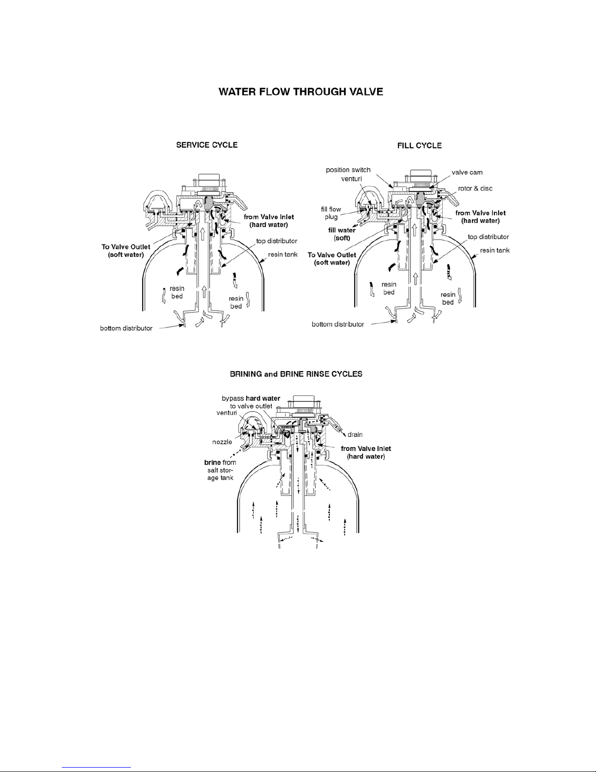
o FILL: Salt, dissolved in water, is called brine. Brine is needed to clean the
hardness minerals from the resin beads. To make the brine, water flows into
the salt storage area during the fill stage as shown on page 17.
o BRINING: During brining, brine travels from the salt storage area, into the
resin tank. Brine is the cleaning agent needed to remove the hardness
Page 17
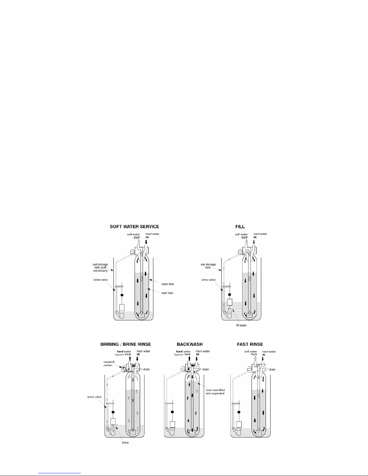
17
minerals from the resin beads. The hardness minerals, and brine are
discharged to the drain. The nozzle and venturi create a suction to move the
brine, maintaining a very slow rate to get the best resin cleaning with the least
salt.
o BRINE RINSE: After a pre--measured amount of brine is used, the brine
valve closes. Water continues to flow in the same path as during brining,
except for the discontinued brine flow. Hardness minerals and brine flush
from the resin tank, to the drain.
o BACKWASH: During backwash, water travels up through the resin tank at a
fast flowrate, flushing accumulated iron, dirt, and sediments from the resin
bed and to the drain.
o FAST RINSE: Backwash is followed by a fast flow of water down through the
resin tank. The fast flow flushes brine from the bottom of the tank, and packs
the resin bed. After fast rinse, the softener returns to soft water service.
AUTOMATIC HARD WATER BYPASS DURING REGENERATION
For emergency needs, hard water is available to the home during the regeneration
cycles. However, you should avoid using HOT water because the water heater will refill
with the hard water.
WATER FLOW THROUGH SOFTENER
Page 18
18
GENERAL WATER SOFTENER MAINTENANCE AND
TROUBLESHOUTING
CHECKING THE SALT STORAGE LEVEL, AND REFILLING
Brine (salt dissolved in water) is needed for each and every regeneration. The water for
making brine is metered into the salt storage area by the softener valve and timer.
However, you must keep the tank full of salt.
NOTE: In humid areas, it is best to fill with less salt, more often.
WHEN TO REFILL WITH SALT:
Check the salt level a few weeks after you install the softener and every week after that.
Refill when the brine tank is from1/3 to 1/2 full. Never allow the softener to use all the
salt before you refill it. Without salt, you will soon have hard water. Use clean water
softener salts only, at least 99.5% pure. NUGGET, PELLET or coarse SOLAR salts are
recommended. Do not use rock, block, granulated, and ice cream making salts. They
contain dirt and sediments, or mush and cake, and will create maintenance problems.
NOTE: WATER SOFTENING SALT WITH IRON REMOVING ADDITIVES:
Some salts have an additive to help the softener handle iron in the water supply.
Although this additive may help to keep the softener resin clean, it may also release
corrosive fumes that weaken and shorten the life of some softener parts.
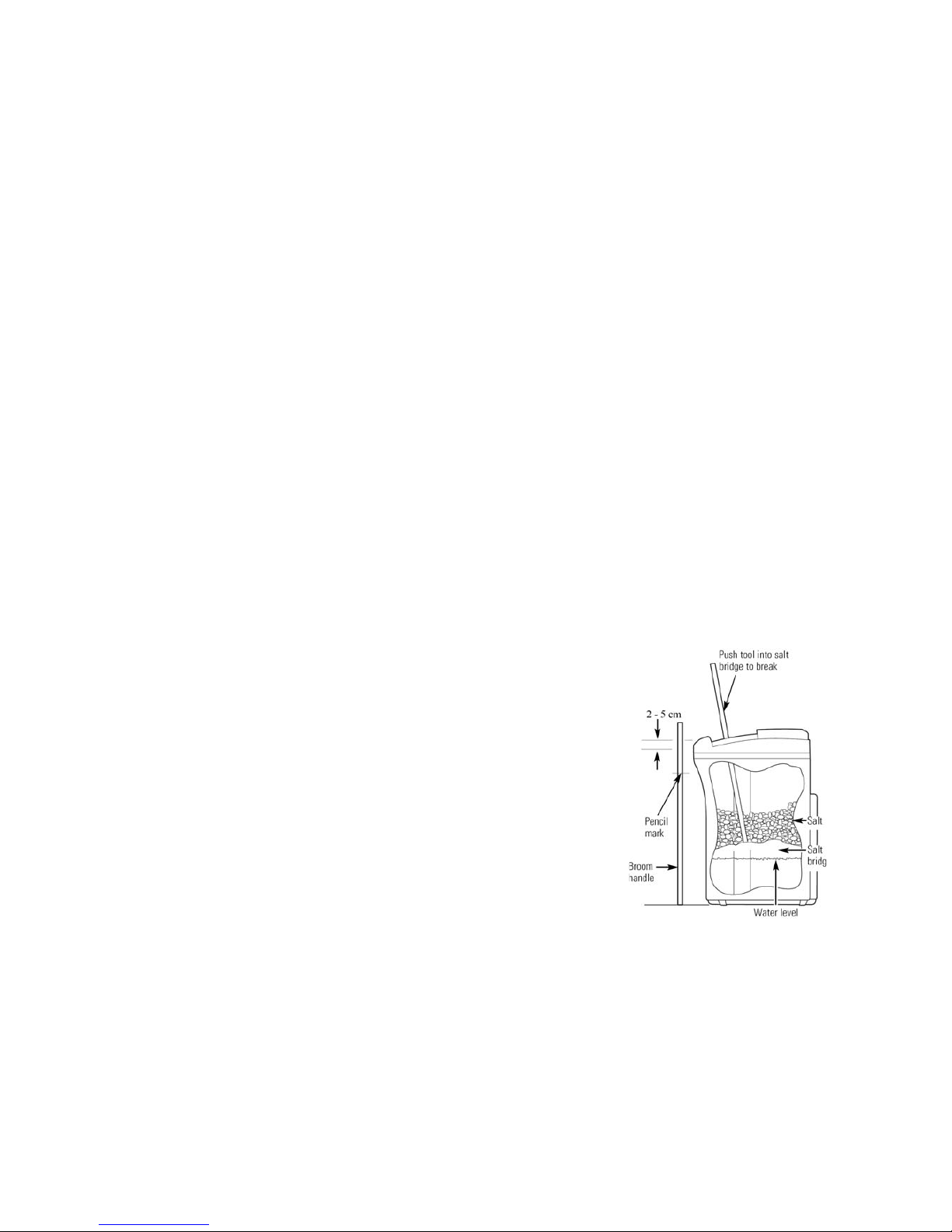
BREAKING A SALT BRIDGE
Sometimes, a hard crust or salt bridge forms in the
salt storage area. It is usually caused by high humidity
or the wrong kind of salt. When the salt bridges,
an empty space forms between the water and salt.
Then salt will not dissolve in the water to make brine.
If the brine tank is full of salt, it is hard to tell if you
have a salt bridge. Salt is loose on top, but the bridge
is under it. The following is the best way to check for
a salt bridge.
Salt should be loose all the way to the bottom of the
tank. Take a broom handle, or like tool, and carefully
push it down into the salt, working it up and down.
If the tool strikes a hard object (be sure it’s not the
bottom or sides of the tank), it’s most likely a salt
bridge. Carefully break the bridge with the tool.
DO NOT pound on the walls of the tank. If the wrong kind of salt made the bridge, take
it out. Then fill the tank with nugget or pellet salt only.
CLEANING IRON OUT OF THE WATER
Your water softener takes hardness minerals (calcium and magnesium) out of the water.
Also, it can control some (see specifications, page 3) “clear water” iron. With clear water
iron, water from a faucet is clear when first put into a glass. After 15 to 30minutes, the
Page 19
19
water begins to cloud or turn rust colored. A water softener WILL NOT remove any iron
that makes the water cloudy or rusty as it comes from the faucet (called red water iron).
To take red water iron out of water, or over the maximum of clear water iron, an iron filter
or other equipment is needed. Your local dealer has trained people to help you with iron
water problems. If your water supply has clear water iron, periodic resin bed cleaning is
needed. Clean the bed at least every six months, or more often if iron appears in the
soft water between treatments. Follow directions on the resin bed cleaner container.
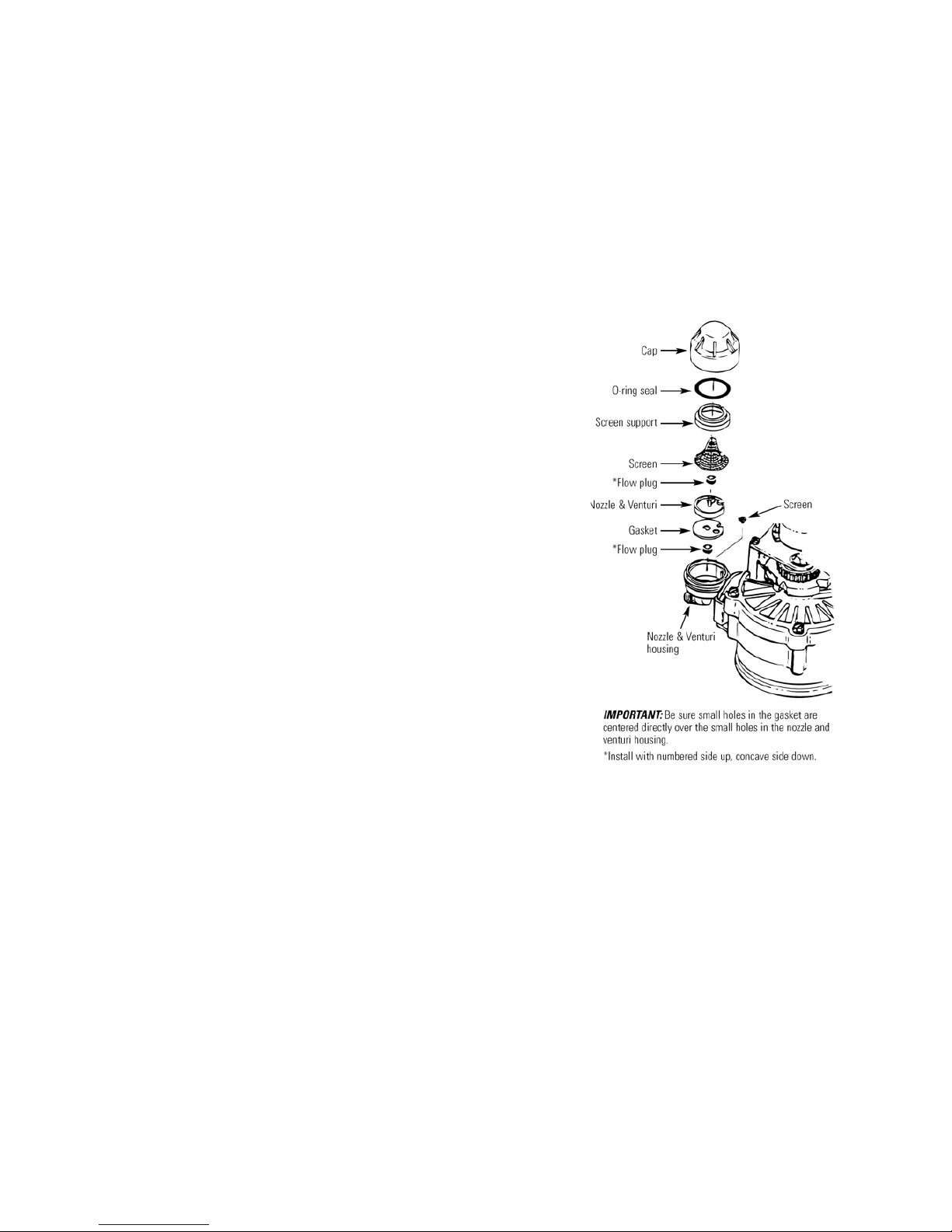
CLEANING THE NOZZLE AND VENTURI
A clean nozzle and venturi is needed for the softener
to work right. This small unit makes the suction
to move brine from the salt storage area to the
resin tank during regeneration. If it becomes
plugged with sand, silt, dirt, etc., the softener will not
work and you will get hard water.
To get to the nozzle and venturi, remove the softener
top cover. Be sure the softener is in service cycle (no
water pressure at nozzle and venturi). Then, while
holding the nozzle & venturi housing with one hand,
turn off the cap. Lift out the screen support and
screen, then the nozzle and venturi. Wash and rinse
the parts in warm water until clean. If needed, use
a small brush to remove iron or dirt. Also check and
clean the gasket.
NOTE: Some models have a small flow plug located
in the nozzle and venturi, and/or a small cone
shaped screen in the housing. Be sure to check and
clean these parts, if your model is so equipped.
Carefully replace all parts in the correct order. Lubricate
the o-ring seal with silicone grease and place
in position. Install and tighten the cap, BY HAND
ONLY.DO NOT OVER-TIGHTEN AND BREAK THE
CAP OR HOUSING.
SERVICE CHECKLIST
NO SOFT WATER
o No salt in storage tank: See page 18 to refill, then start a regeneration, or
recharge.
o Transformer unplugged at wall outlet, or disconnected from timer:
Reconnect to electrical power and start a regeneration, or recharge.
o Fuse blown, circuit breaker popped, or circuit mistakenly switch ed of f:
Check and resolve as needed. Then, start a regeneration, or recharge.
o Plumbing bypass valve(s) in ‘‘bypass’’ position: Refer to page 6 and position
valve(s) as needed to direct soft water to house pipes. Then, start a
regeneration, or recharge.
Page 20
20
o Timer not programmed: See.... Electronic Demand Timer -- page 11. Nozzle &
venturi dirty, or salt in storage tank bridged: See page 19, and above to
clean. Then, start a regeneration, or recharge.
W
WATER INTERMITTENTLY HARD
o
Possible increase in water hardness: See.... Electronic Demand Timer -- page
10.
o Hot water used when softener is regenerating: The water heater will refill with
hard water... see Automatic Hard Water Bypass During Regenerations, page 17.
o Leaking faucet or toilet valve: A small leak will waste hundreds of liters of
water in just a few days. Fix all water leaks immediately.
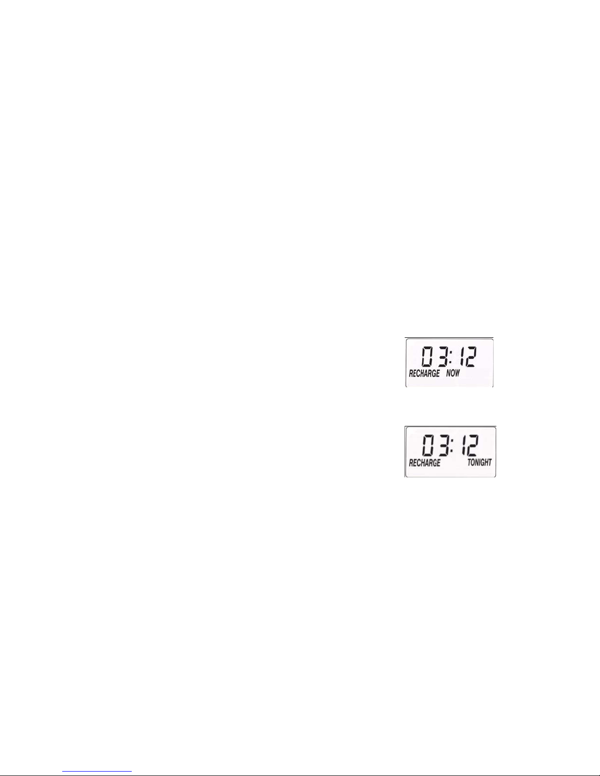
OPTIONAL RECHARGE
Sometimes, a manually started regeneration (recharge) may be desired, or needed. Two
examples are:
o You have used more water than usual (house guests, extra washing, etc.) and
you may run out of soft water before the next regeneration.
o You did not refill the storage tank with salt before it was all gone.
Use one of the following features to start a regeneration immediately, or at the next
preset regeneration start time.
RECHARGE NOW
Press and hold in the TOUCH - HOLD button until
RECHARGE NOW starts to flash in the time display area.
The softener begins an immediate regeneration, and when
over in about two hours, you will have a new supply of soft water.
Once started, you cannot cancel this regeneration.
RECHARGE TONIGHT
Touch (do not hold) the TOUCH - HOLD button, and
RECHARGE TONIGHT flashes in the time display area.
A regeneration will occur at the next preset regeneration
start time. If you decide to cancel this regeneration,
touch the same button once more.
VACATION
A-Star Demand water softeners regenerate only while water is used and softening
capacity must be restored. For this reason, the softener will not regenerate when you are
away from home for extended periods.
Page 21
21
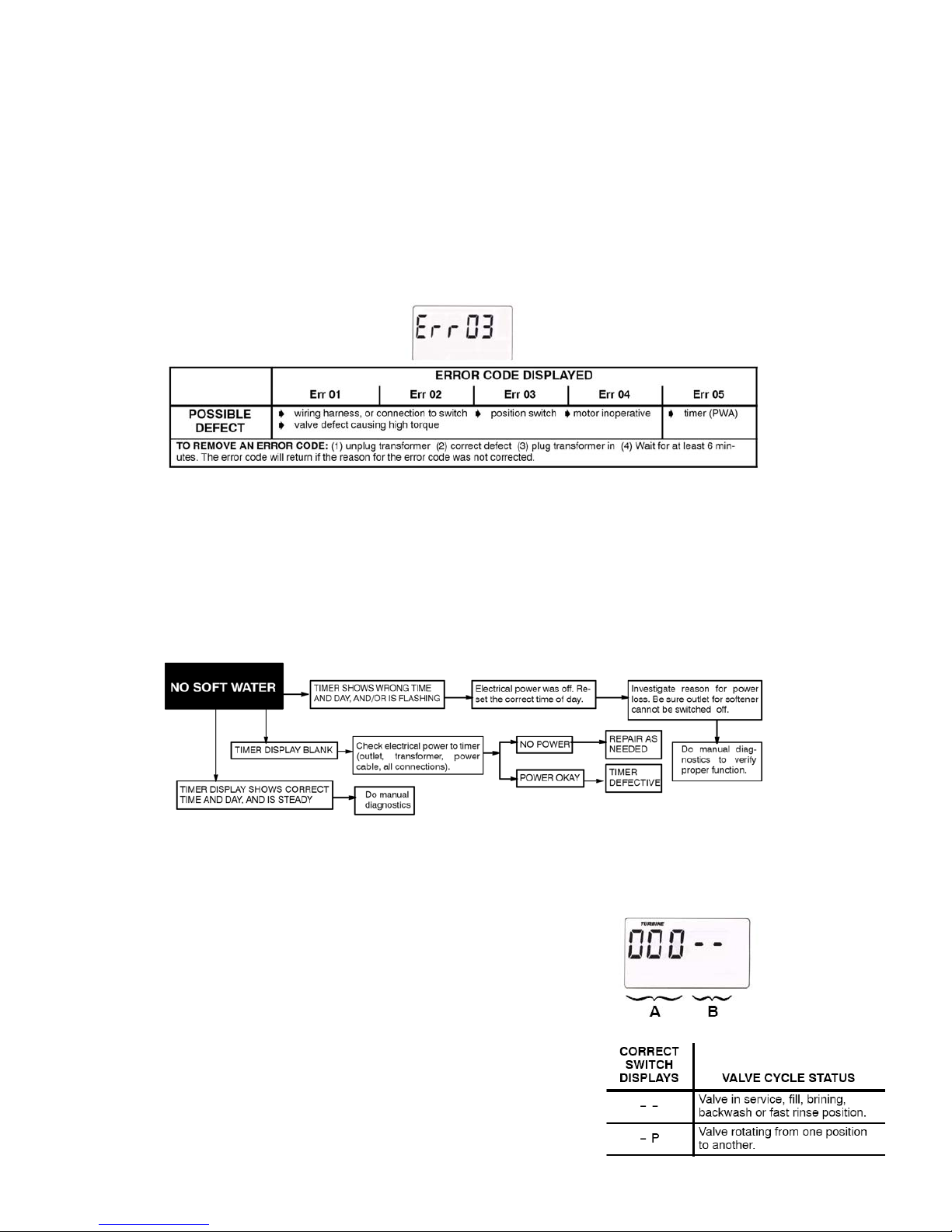
AUTOMATIC ELECTRONIC DIAGNOSTICS
The timer computer has a self-diagnostic function for the electrical system (except input
power and water meter). The computer monitors the electronic components and circuits
for correct operation. If a malfunction occurs, an error code appears in the
timer display. The following chart (below) shows the error codes that could appear, and
possible defects for each code. While an error code is displayed, all timer buttons are
inoperable except for the SELECT button. SELECT remains operational so the service
person can make the Manual Initiated Electronic Diagnostics to further isolate the defect,
and check the water meter.
TIMER / SOFTENER, SERVICE CHECKOUT
If you are not getting soft water, and an error code is not displayed, use the procedures
below to find the problem. First, make the following visual checks.
VISUAL CHECKS:
(1) Is there electrical power to the outlet the softener transformer is plugged into?
(2) Is there salt in the storage tank?
(3) Is the plumbing bypass valve(s) directing water for soft water service?
(4) Is the valve drain hose open to the drain, not elevated too high, and unobstructed? If
you do not find a problem with the visual checks, continue below.
MANUAL INITIATED ELECTRONICS DIAGNOSTIC
1. To enter diagnostics, press and hold the SELECT button until (000 -- --) shows in the
display.
(A)The first 3 digits indicate water meter operation
as follows:
' 000 (steady) = soft water not in use −> no flow
through the meter.
— OPEN A NEARBY SOFT WATER FAUCET —
' 000 to 199 (continual) = repeats display for each
gallon of water (=3.78 litres) passing through the meter.
If you don’t get a reading in the display, with faucet open,
pull the sensor from the valve outlet port.
Page 22
22
Pass a small magnet back and forth in front of the sensor.
You should get a reading in the display. If you get a reading,
unhook the in and out plumbing and check the turbine for
binding.
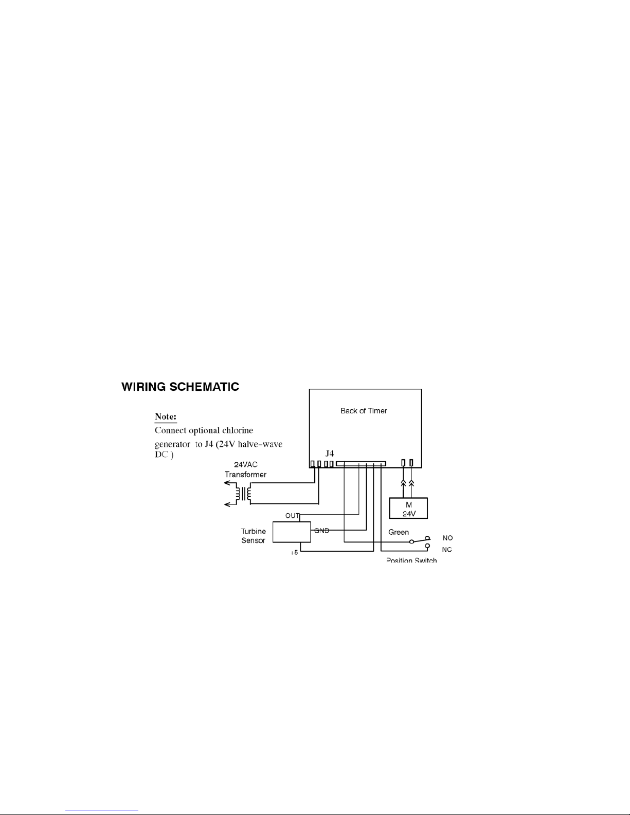
(B) The letter (P) and dash(es) indicate POSITION switch
operation. The letter appearing means the switch is closed; the dash means the
switch is open. Use the TOUCH - HOLD (Recharge Tonight -- Now) button to
manually advance the valve into each cycle and check correct switch operation.
Note: While in this diagnostic screen, the following information is available and may be
beneficial for various reasons. This information is retained by the computer from the first
time electrical power is applied to the face plate.
o Press the UP▲ button to display the number of days this face plate has had
electrical power applied.
o Press the DOWN ▼ button to display the number of regenerations initiated by
this face plate since the Model code number was entered.
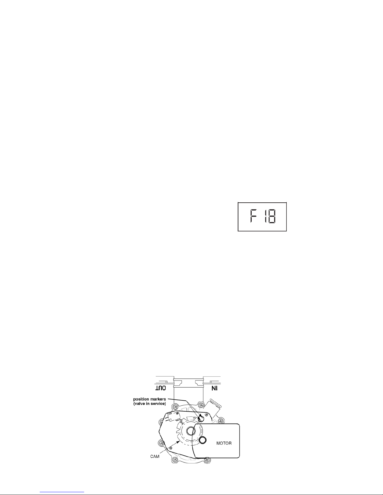
2. Press the SELECT button and hold in 3 seconds until a Mode code appears in the
display. For correct softener operation, the F 18 number must be indicated.
o To reset the code, press the UP ▲ or DOWN ▼
button until the correct number shows.
3. Press SELECT to return the present time display. If the code was changed, make
ALL the timer settings.
NOTE: If the face plate is left in a diagnostic display (or a flashing display when setting times or
hardness), present time automatically returns if a button is not pressed within 4 minutes.
MANUAL ADVANCE REGENERATION CHECK
This check verifies proper operation of the valve motor, brine tank fill, brine draw,
regeneration flow rates, and other controller functions. First, make the initial checks,
and the manual initiated diagnostics.
NOTE: The face plate display must show a steady time (not flashing).
1. Press the TOUCH - HOLD button and hold in for 3 seconds. RECHARGENOW begins
to flash as the softener enters the fill cycle of regeneration. Remove the brine well
cover and, using a flashlight, observe fill water entering the brine tank.
⇒ If water does not enter the tank, look for an obstructed nozzle, venturi, fill flow
plug, brine tubing, or brine valve riser pipe.
Page 23
23
2. After observing fill, press the TOUCH – HOLD button to move the softener into
brining. A slow flow of water to the drain will begin. Verify brine draw from the brine
tank by shining a flashlight into the brine well and observing a noticeable drop in the
liquid level.
NOTE: Be sure a salt bridge is not preventing water with salt contact.
⇒ If the softener does not draw brine:
o nozzle and/or venturi dirty or defective.
o nozzle and venturi not seated properly on gasket.
o restricted drain (check drain fitting and hose).
o defective nozzle and venturi seal.
o other inner valve defect (rotor seal, rotor & disc, wave washer, etc.).
NOTE: If water system pressure is low, an elevated drain hose may cause back
pressure, stopping brine draw.
3. Again, press the TOUCH - HOLD button to move the softener into backwash. Look for
a fast flow of water from the drain hose.
⇒ A slow flow indicates a plugged top distributor, backwash flow plug, or drain hose.
4. Press TOUCH - HOLD to move the softener into fast rinse. Again look for a fast drain
flow. Allow the softener to rinse for a few minutes to flush out any brine that may
remain in the resin tank from the brining cycle test.
5. To return the softener to service, press TOUCH - HOLD.
Page 24
24
Page 25
25
Page 26
26
Page 27

27
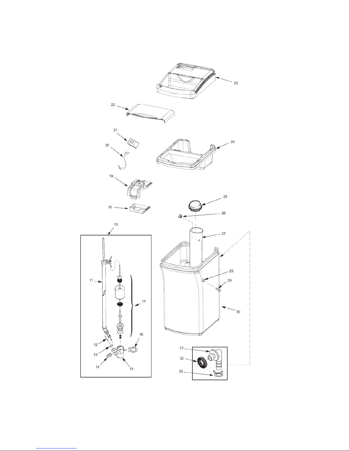
Key No Req’d Description Part N°
1 2 Clamp Section 7176292
2 2 Retainer Clamp 7088033
3 1 O-ring, 2-7/8 x 3-1/4 7170296
4 1 O-ring, 13/16 x 1-1/16 7170254
5 1 O-ring, 2-3/4 x 3 7170270
6 1 Top Distributor 7077870
7 1 Rep’l Bottom Distributor 7105047
8 1 Rep’l Resin Tank Pkd 7197468
9 1 cu. ft Resin 502272
10 1 Brine Valve Assembly 7264207
11 1 Brine Tube 7152989
12 1 Tubing Assembly 7113016
13 1 Screen 7131365
14 1 Clip 7080653
15 1 Brine Valve Body 7092252
16 1 Clip 1205500
17 1 Float, Stem & Guide Assembly 7269508
18 1 Electronics Enclosure Rear 7269930
19 1 Face Plate (order decal below) 7281089
1 Decal, Face Plate 7281102
20 1 Power Cord 7250826
21 1 Rep’l PWA 7281823
22 1 Salt Lid 7281055
23 1 Cover, Top 7281039
24 1 Rim 7281047
25 1 Brinewell Cover Assembly 7155115
26 1 Wing Nut 7082150
27 1 Brinewell w/Decal 7263099
28 1 O-Ring 7003847
29 1 Screw 7148875
30 1 Rep’l Brine Tank Pkd 7287815
31 1 Hose Adaptor 1103200
32 1 Grommet 9003500
33 1 Hose Clamp 900431
Page 28
28
Page 29

29
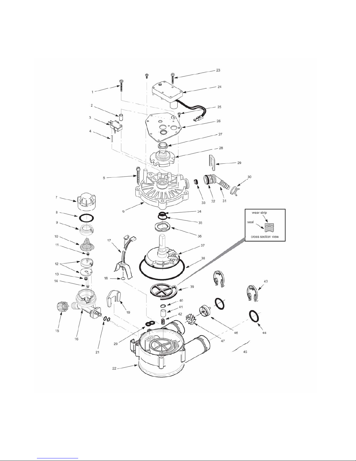
Key No Req’d Description Part N°
1 1
Screw, #4-24 x 1-1/8”
7070412
2 1
Spacer
7117816
3 1
Switch
7030713
4 1
Expansion Pin
7077472
5 5
Screw, #10-14 x 2”
7074123
6 1
Valve Cover
7085263
7 1
Cap
7199729
8 1
O-ring Seal, 1.1” x 1.4”
7170262
9 1
Screen Support
7167659
10 1
Screen
7146043
11 1
Flow Plug
521829
12 1
Nozzle & Venturi with Gasket
7114533
13 1
Fill Flow Plug
1148800
14 1
Cone - Screen
7095030
15 1
Nut - Ferrule
1202600
1
Nozzle & Venturi Assembly
7187065
16 1
Nozzle & Venturi Housing
7081104
17 1
Sensor Housing
7276076
18 1
O-ring
900060
19 1
Retainer
7081201
20 1
Seal (Nozzle & Venturi)
7081764
21 2
O-ring Seal, 1/4” x3/8”
7170319
22 1
Valve Body
7082053
23 2
Screw, #8-32 x 1”
7224087
24 1
Motor (includes Key No. 23)
7286039
25 2
Screw, #6-20 x 3/8”
900857
26 1
Motor Plate
7288198
27 1
Bearing
503288
28 1
Cam & Gear
7284964
29 1
Clip
7142942
30 1
Hose Clamp
900431
31 1
O-ring Seal, 5/8” x 13/16”
7170327
32 1
Drain Hose Adaptor
7024160
33 1
Flow Plug, Backwash & Fast Rinse
501228
34 1
O-ring Seal, 7/16” x 5/8”
7133464
35 1
O-ring Seal, 3/4” x 15/16”
7133472
36 1
Wave Washer
7082087
37 1
Rotor & Disc
7199232
38 1
O-ring Seal, 3-3/8” x 3-5/8”
7170246
39 1
Rotor Seal
7123639
1
Wear Strip
7126433
40 1
O-ring Seal, 3/8” x 9/16”
7133456
41 1
Plug (Drain Seal)
7092642
42 1
Spring
7129889
43 2
Clip
7116713
44 2
O-ring Seal, 15/16” x 1-3/16”
7133498
45 1
Turbine & Support Assembly (incl Key nr. 46 and 47)
7147243
 Loading...