

Page 1
108 Industrial Avenue
New Orleans, LA 70121
Phone (504) 837-5575
Fax (504) 837-5585
Info@astfilters.com
www.ASTfilters.com
Updated 08/10/16 V1-AST
Page 2

1
Table of Contents
Introduction to the HPPG Series ................................................................................................................... 2
Operation ...................................................................................................................................................... 2
Backwash Operation Overview ..................................................................................................................... 0
HPPG Bead Filter Major Components ........................................................................................................... 3
Installation .................................................................................................................................................... 4
Pump Configuration .................................................................................................................................. 4
Airlift Configuration .................................................................................................................................. 6
Backwash Air Pump ....................................................................................................................................... 8
General Setup Directions ........................................................................................................................ 10
Adjusting your Backwash Frequency ...................................................................................................... 11
Sludge Drainage Assembly .......................................................................................................................... 14
Air Pump Requirements for Backwashing .............................................................................................. 15
Backwash Frequency ............................................................................................................................... 15
Troubleshooting (Filter Function) ............................................................................................................... 17
Trouble Shooting for Recirculating Aquaculture Applications ............................................................ 20
Sulfide Production ....................................................................................................................................... 21
Filter Acclimation ........................................................................................................................................ 22
Appendix A: The Science behind Bioclarification ........................................................................................ 27
Clarification ............................................................................................................................................. 27
Biofiltration ............................................................................................................................................. 29
Warranty. .................................................................................................................................................... 32
Page 3

2
Introduc�on to the HPPG Series
The High Pressure PolyGeyser® (HPPG) blter series is the newest addon to Aquaculture Systems
Technologies’ line of bead lters. Patented ( U.S. Patent #9,227,863 Patent Pending , European
Patent #0977713B & Canadian Patent #2,287,191) fully exploits the biolm protecon provided by our
Enhanced Nitricaon (EN) Bead Media in a durable berglass hull. Designed as “bioclaris” capable
of performing both biological and mechanicalaon, PolyGeyser
biological loads 50% to 100% higher than our Bubble Bead o
standard bead media. Addionally, the PolyGeyser
®
Bead Filters are virtually immune to clogging and
r Propeller Bead Filters equipped with
caking, since they are backwashed pneumly at a high frequency. These High Pressure PolyGeyser
(HPPG) Bead Filters recycle their own backwash waters. The HPPG lters are the bioclari of choice
for commercial aquaculture and wastewater applicaons dealing with high organic loads.
Opera�on
The PolyGeyser® Bead Filter stands apart from AST’s other Bead Filter technologies primarily through its
automneuma backwash mechanism. Water is introduced below the bed of packed EN bea
media and travels upward through the ltraon chamber where mechanical and biologicalltraon
takes place. Simultaneously, air is slowly introduced into the air charge chamber at a constant,
predetermined rate to achieve the desired backwash frequency. Once the charge chamber has reached
capacity, the pneumac trigger res, releasing the entrained air from the charge chamber below the
media bed. The sudden release of air from the charge chamber causes the beads to mix, roll and “drop”
as the air agitates the beads.
®
Bead Filters are capable of handling
d
®
The circulaon pump/airli operates connually
immediately aer each backwash event. This causes the beads to oat upward and reform as a bed.
During the recharge cycle (a few hours), suspended solids in the trapped backwash waters sele into the
sludge storage chamber for later disposal via the sludge drain valve (usually every 3 days- 1 week). At
the same me, the claried backwash waters are passed slowly through the bead bed again eliminng
any backwash water losses.
The eliminaon of water loss associated with backwashing is a key element in this new techn
most applicaons, dozens of backwash sequences can be automly executed before sludge removal
is required. There is no water loss associated with the backwash process and the water loss associated
with sludge drainage is negligible. This strategy is paularly advantageous for marine systems, where
the loss of saltwater must be minimized.
, which ensures that ther chamber begins relling
ology. In
Page 4
3
The pneuma�c strategy breaks the linkage between backwash frequency and water loss and allows the
nitrifica�on capacity of the unit to be fully utilized. Frequent backwash sequences have proven
advantageous for op�mizing the nitrifica�on capacity of the unit. Numerous gentle scrubbing cycles
promote high rates of nitrifica�on by maintaining a healthy thin biofilm on the bead surfaces. Typical
backwash cycles occur once every three to six hours. In recircula�ng bioclarifier applica�ons, where the
High Pressure PolyGeyser
®
Bead Filter operates concurrently as a clarifier and biofilter, total ammonia
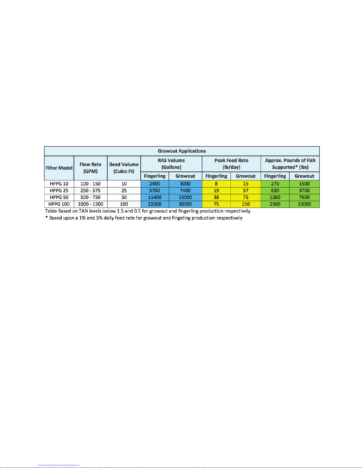
nitrogen (TAN) levels below 0.3, 0.5 and 1.0 mg-N/l can be expected at feed loading rates of 0.5, 1.0 and
1.5 pounds feed per cubic foot of EN bead media (8, 16 and 24 kg-feed m
-3
day-1), respec�vely.
Table 5. High Pressure
PolyGeyser
®
Bead Filter Specifica�ons
Page 5

Backwash Operation Overview
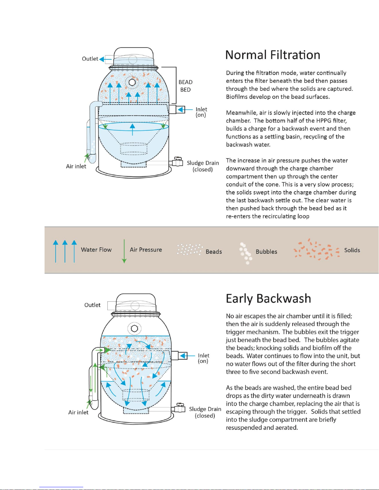
The PolyGeyser filter is a breakthrough in filter technology. It features an advanced auto-pneumatic
backwash mechanism. Water enters below the bed of enhanced nitrification media and travels upward
through the filtration chamber where mechanical and biological filtration take place. Simultaneously, air
is introduced into the charge chamber at a constant predetermined rate to achieve the desired
backwash frequency.
Once the charge chamber has reached capacity, the pneumatic trigger fires. This releases the entrained
air from the charge chamber below the bead bed. The sudden release of air from the charge chamber
causes the beads to mix as the air agitates the beads. As the beads drop, the bead bed expands
downward while water rushes downward through the expanded beads, sweeping the solids away and
into the air charge chamber.
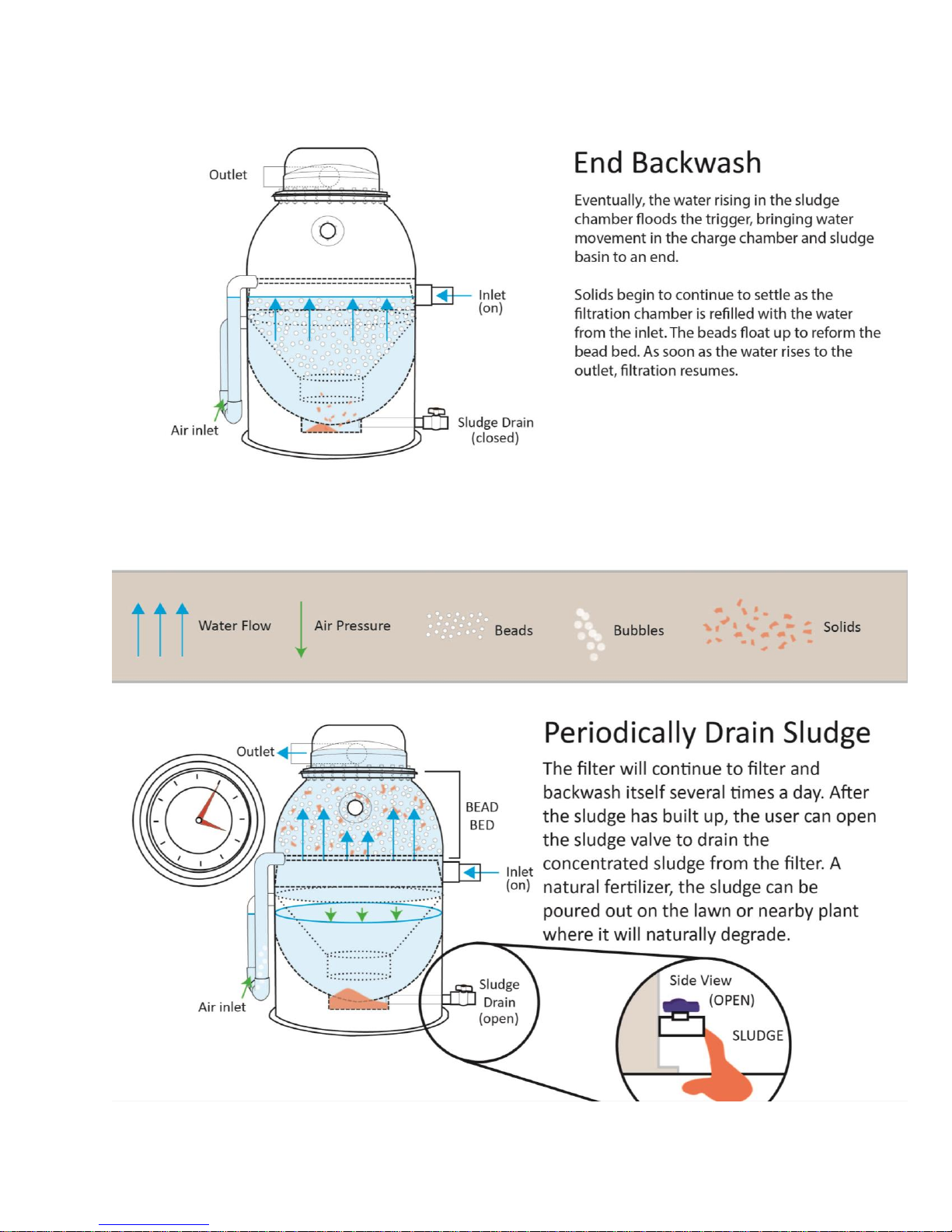
In the chamber, the solids settle out from the backwash waters and are later removed from the filter.
Essentially, this type of filter recycles the backwash water while concentrating the waste products so
that you have extremely low water loss while maximizing the nitrification capacity.
Frequent backwashing has proven advantageous for optimizing the nitrification capacity of a
Polygeyser® filters. Numerous gentle scrubbing cycles promotes a higher rate of nitrification by
maintaining a healthy thin biofilm on the surface of the bead media. Typical backwash cycles occur every
3-6 hours.
Page 6
1
Page 7
2
-
Page 8
3
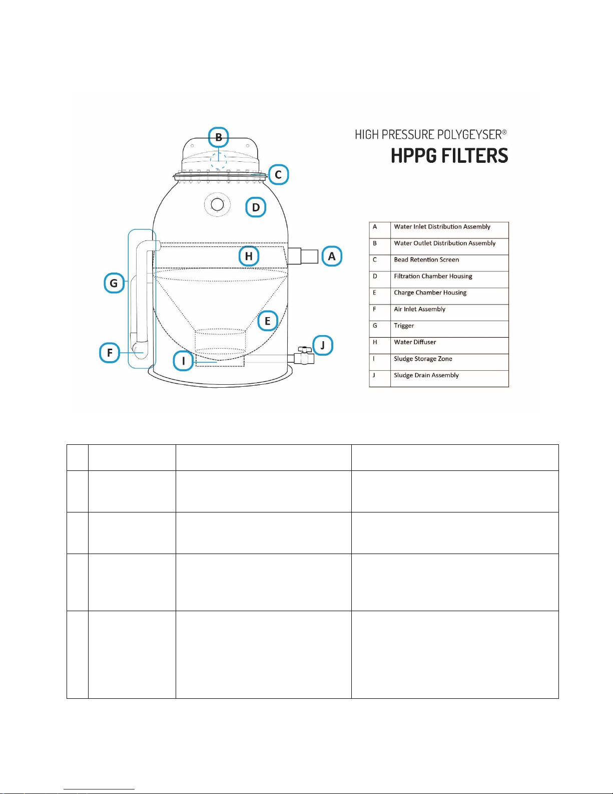
HPPG Bead Filter Major Components
Descriptor
Function
Comment
A
Inlet
Directs flow into filter via the
diffuser
B
Screen
Passes water while retaining the
beads in the filter
C
Outlet
Directs the filtered water into the
return lines.
Multiple outlets are generally used for
airlift models to lower water velocity and
hydraulic friction
D
Bead Bed
Captures suspended solids while
providing surface area for biological
processes, such as nitrification, used
to restore water to a pristine
condition
The beads float to form tightly packed
granular bed ideal for physical and
biological filtration. Beads are typically 2-3
mm in diameter.
Table 6. Major Component List – Basic Configuration
Page 9

4
E
Charge Chamber
The air tight cone defines the charge
chamber while forming a conduit for
water transmission into and out of
the charge chamber
In this design series, the charge chamber is
wrapped around the centralized conduit
which re-suspends and aerates sludge
during each backwash event
F
Air Inlet
Slowly fills the charge chamber with
air
Air is added at a slow rate so that it takes a
few hours to fill the charge chamber.
G
Trigger
Catastrophically releases air from
the charge chamber once it is filled
H
Diffuser
Redirects the incoming water
beneath the bead bed.
Hydraulically designed to minimize
turbulence that may erode the bed.
I
Sludge Basin
Provides for temporary sludge
storage.
The sludge that is released from the bead
bed during a backwash settles out of the
cone and charge chamber that can be
removed periodically as a thick sludge
through the sludge outlet.
J
Sludge Outlet
Facilitates the removal for thickened
sludge from the unit.
Sludge is typically concentrated to 10,00020,000 mg/L in the HPPG series.
Cap
Directs flow from the screen to the
Outlet pipe(s)
The cap assembly also includes gaskets that
seal the screen to the filter hull.
Installation
Installation will require that you hook up a water pump to circulate water through the filtration bed and
an air compressor to fill the charge chamber for the back wash sequence. Filters in the HPPG series are
most frequently paired with a low head centrifugal pump capable of delivering a high rate of flow at
relatively low pressures (5-10 psi). However, in commercial scale recirculating aquaculture
applications, the units can be paired with airlifts to minimize energy consumption. Use of airlifts,
however, generally requires lowering (burying) the unit so water can be filtered by gravity and then
airlifted back up. With total filtration head losses beneath 0.5 psi, use of airlifts can be attractive
whenever the physical configuration permits.
The backwashing air source must be matched with the circulation method you select. Simply stated the
air pressure must exceed the water pressure for air to flow into the unit.
Pump Configuration
A self-siphoning, above ground, centrifugal water pump can be used to circulate water through an
HPPG. The unit should have a water delivery capacity of 10-15 gallons per minute for each cubic foot of
Page 10
5
media at the operational pressure for the unit (typically in the range of 5-15 PSI). The shutoff pressure
off the pump should be less than 20 psi, or near 20 psi when a pressure relief is installed to avoid
damaging the HPPG hull.
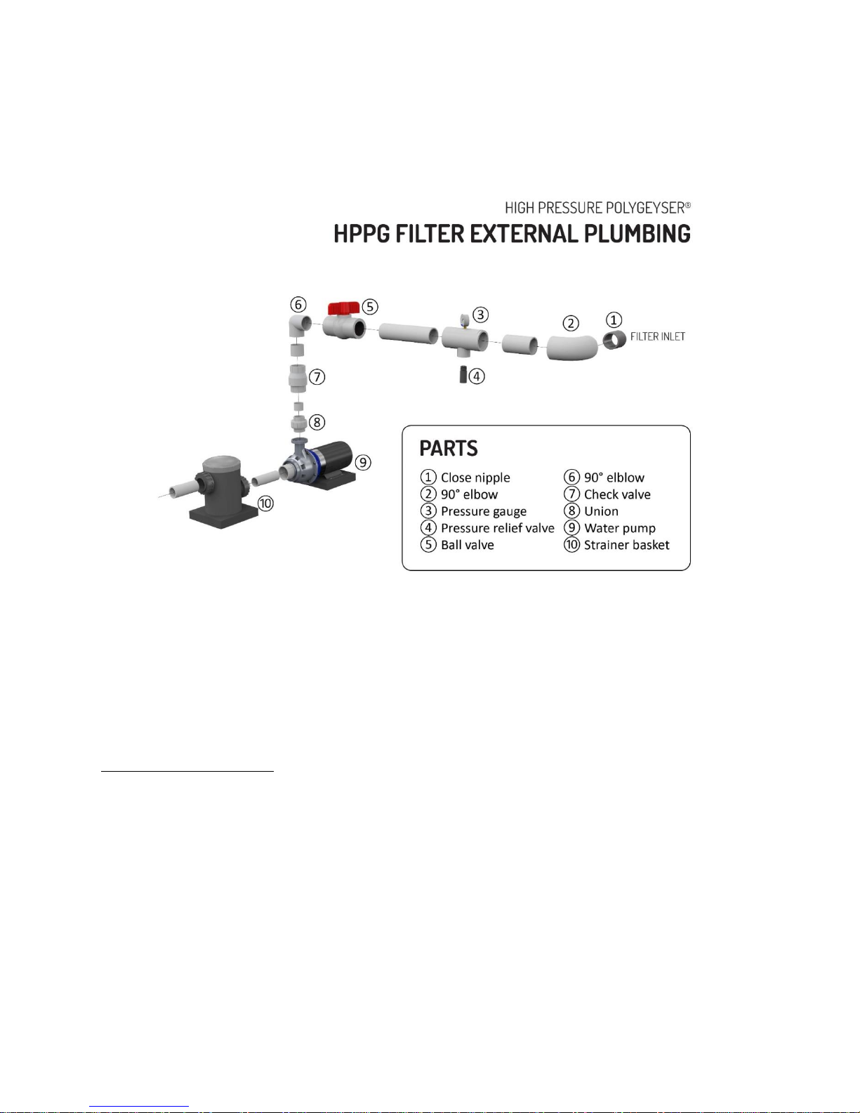
HPPG Filter External Plumbing illustrates a typical plumbing arrangement. In most case the pump (9)
should be protected by a screen or an inline screen basket (10). Many pumps already have the inline
basket attached. A hard PVC couple (8) is placed immediately adjacent to the pump discharge to
facilitate pump replacement or servicing. A rubber or flexible couple should be avoided here, as they
are sensitive to pump vibration tend to work loose. This coupling is followed immediately by a
mandatory check valve (7) which prevents the backflow of beads into the pump during periods of
power interruption. If the pump’s flow capacity is significantly greater than the filters rating then a ball
valve (5) is then placed in line to allow the pump to be throttled to manage flow through the HPPG unit.
Alternately a “tee” can be placed at this location with two ball valves allowing for flow to bypass the unit
to a parallel use. You will find a 0-30 psi pressure gauge (3) will greatly facilitate the management of
the filter. High pressures are an indication to increase the backwash frequency. Finally, in situations
where either the water pump or the backwashing air pump have high shutoff pressures (>20 psi) then
a pressure relief valve must be placed immediately adjacent to the filter input to assure protection of
the hull. The pressure relief valve can be set to pop at 20 psi. All HPPG filters are pressure tested at a
higher pressure to ensure quality prior to shipping, but the operational pressures should not exceed 20
psi.
Page 11
6
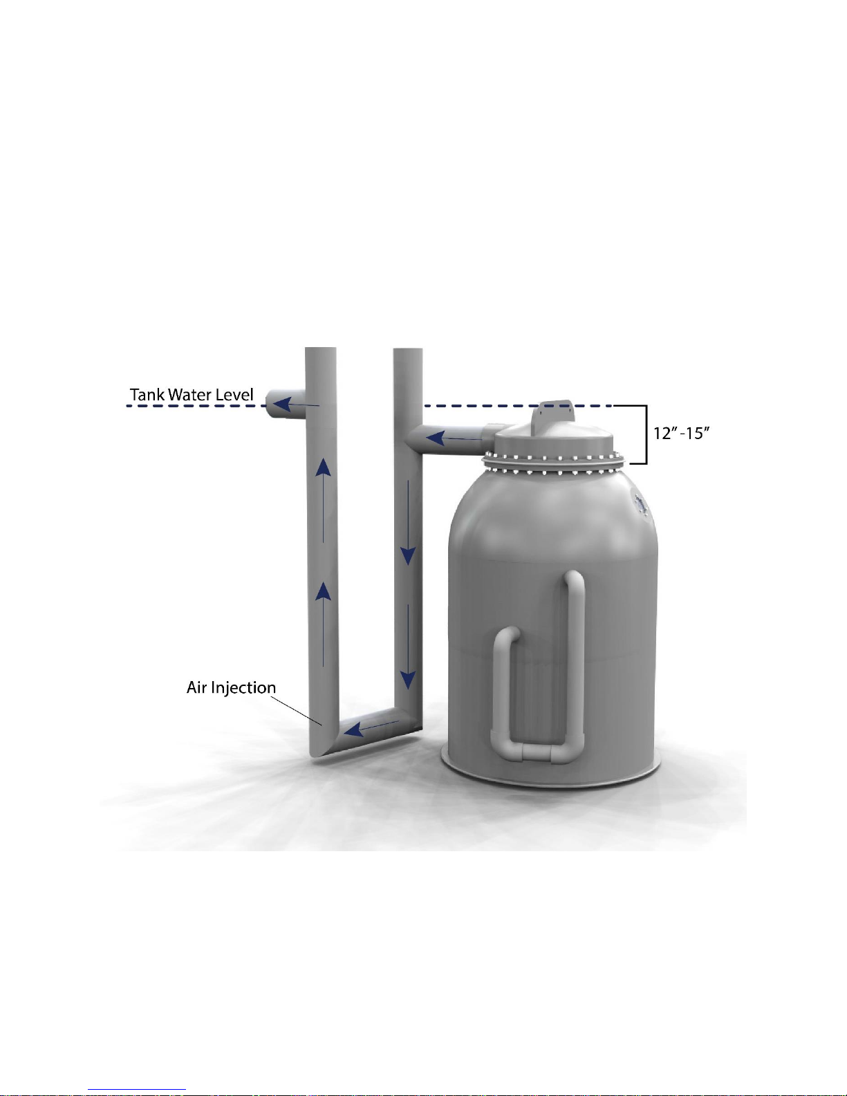
Airlift Configuration
The HPPG series is equipped with an oversized screen and inlet/outlet plumbing to facilitate airlift
operation. Typically, the filter must be positioned next to the tank so that the screen is 12-15” below
the water level in the tank. The siphoning outlet pipes are then directed toward the ground to develop
pressure for the airlift operation. The discharge pipes are then curve back to the vertical draft tube. Air
is injected near the bottom of the draft tube to create a low density air/water mixture that is pushed
upward by the dense water in the siphon line. The elevated air and water mixture is then moved
horizontally to the tank.
Water Flow in an Airlifted HPPG: Water exits from the top of the filter, into the U pipe. Air injected into
the far draft tube pushes the water up and out of the pipe, back into the tank.
Page 12
7
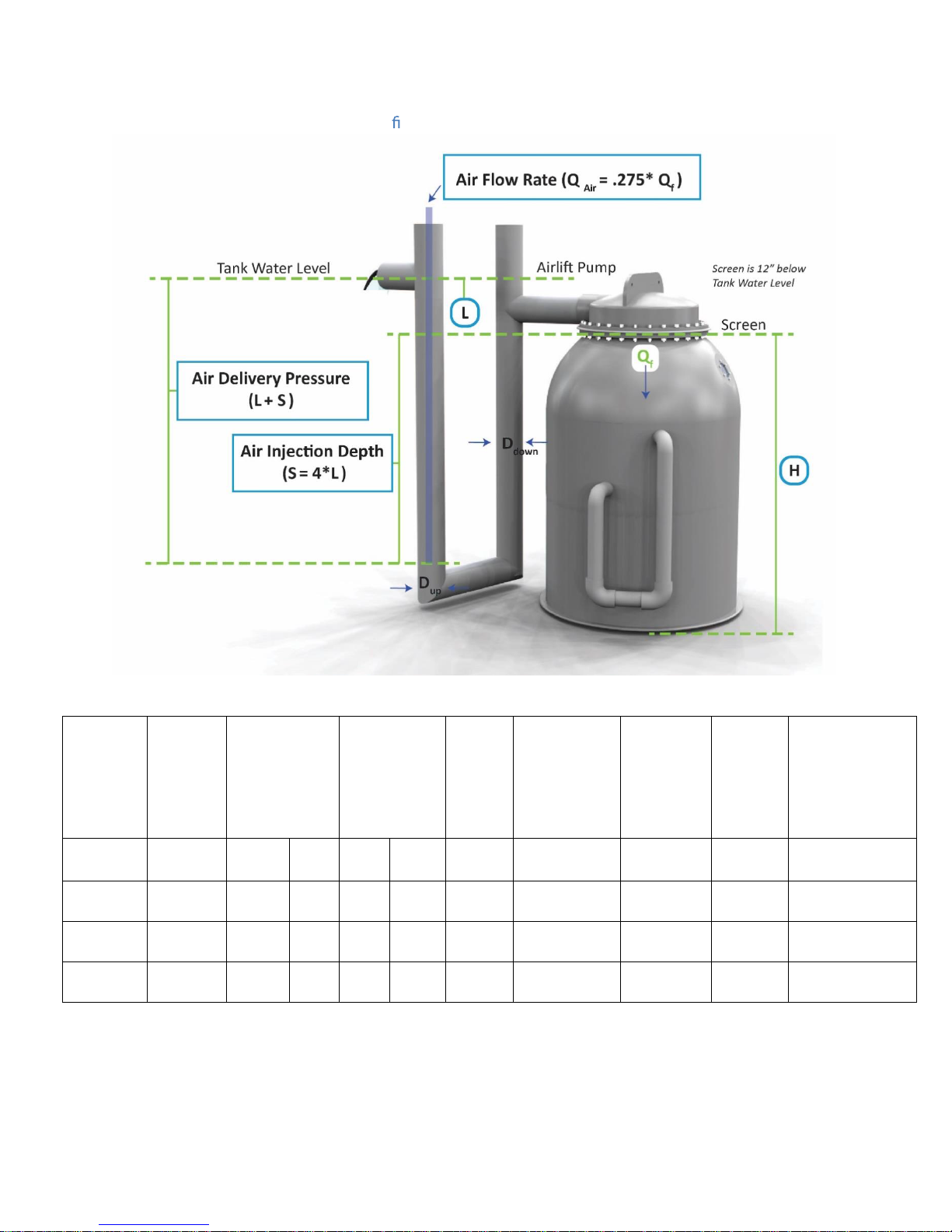
Air Flowrate Calculations for Airlift Con guration
Model
Flowrate
Outlet
Flow
Screen
Air Li
Air
Air
Air Flowrate
(D
)
(D
)
(Vin)
(Vli)
(H)
(L)
(S)
(L+S)
HPPG-10
150 4 6
3.84
1.69
83
12
48
60
41
HPPG-25
300 68
3.37
1.94
80
12
48
60
83
HPPG-50
750 8 12
4.86
2.17
111
12
48e
60
206
Table 8. Air Flowrate Calculaons
(Qf, gpm)
Pipe Size (in)
down
li
Velocity
( /s)
Level
(in)
Requirement
(in)
Injecon
Depth (in)
Delivery
Pressure
(in)
(Qair, scfm)
Page 13

8
Backwash Air Pump
Backwash air pumps are required to operate an HPPG filter. If you have not purchased a backwash
pump with your HPPG filter, you require a low volume continuous duty pumps that is sized to sustain
the appropriate backwash frequency for your filter model. The pump must also be compatible with the
pressure range that is appropriate to the filter. Noise will be generated by the pump, so placement
should be carefully considered. If the pump is placed outside or in a wet room, it should be properly
insulated from water and condensation.
The operational pressure for air injection into the charge chamber of a water pump driven HPPG filter
with a free discharge out of the outlet pipe should be in in the range of 4-6 psi if the backwash
frequency is set properly. At design flow rates about half of this pressure is attributed to the physical
depth of the air injection, the balance is attributed to baseline friction loss through the bead bed or
fittings. If the backflush frequency is set too low, the pressure loss across the bead bed will increase. In
the extreme, the hull pressure will be defined by the shutoff pressure of the pump. The air pump should
be sized to overcome this pump shutoff pressure. Ideally, the air pump and water pumped should be
matched with the air pump having a shut off pressure higher than the pump.
Injection pressures for HPPG airlift applications are controlled by the distance from the tank water
surface to the centerline of the horizontal pipe in the unit’s external trigger (typically a maximum of
about 100 inches or 4 psi). The air injection pressure in an airlifted HPPG does not vary much. An
operational pressure of 5 psi is sufficient.
A medium sized linear air pump is a good choice for airlift applications where backpressures on the
HPPG unit are minimized. These units operate by oscillating a rubber diaphragm that moves air through
a series of valves. These pumps are readily available in weather resistant configurations used for pond
and home packed wastewater treatment units. The flow rates delivered by these blowers are generally
in excess of the backwashing needs, so the unit should be selected based upon its maximum operational
pressure. The larger liner pumps have shutoff pressures in the range of 10 psi which is suitable for most
HPPGs where the unit is not back pressured by downstream devices. Linear air pumps contain a
replaceable rubber diaphragm that will ultimately fail (every 2-3 years depending on the model and
pressure).
A small oil free continuous duty piston pump with an operational pressure rating of about 20 psi is most
ideally suited for delivering air for a wide variety of HPPG applications. These units have small pistons
that are driven directly by a small electric motor. Producing only moderate amount of air, these unit are
recognized for sustained operation at the moderate pressures demanded by HPPG applications.
Capable of delivering a continuous supply of air at the HPPG maximum hull pressure of 20 psi, these
units also display relatively high shutoff pressures that are compatible with a wide variety of pumps.
The air volume produced by this unit is reduced and thus the air delivery capacity should be matched to
the HPPG. These units are most often sized to serve the air demands of a single HPPG unit.
Rotary vane compressors operate in a pressure range (0-15 PSI) well above the more widely recognized
rotary vane blower (0-3 psi). A rotary vane compressor consists of a motor that spins a set of inclined
Page 14

9
high speeds blades that compress and accelerate air into the distribution system. They are capable of
Pump
Typical
Pressure
Range
Comments
Linear Air
0-10 psi
Excellent for backwashing of filters that are nor back pressured
by downstream constrictions, may be over powered by shutoff
head of water pump so should be protected by check valve.
Energy efficient.
Piston
0-30 psi
Generally suitable for all HPPG applications. Capable of
generating pressures in excess of hull pressures thus cannot
be overcome by properly sized water pump.
Rotary vane
compressor
0-15 psi
Suitable for low pressure airlift applications and simplified
pumped configurations. Produce volumes sufficient to
Shop
0-150 psi
Oil free shop (piston) compressors with tank work well as a
backwash air supply provided they are sized large enough to
provide for extended cycle time. Tend to be noisy and over
pressurized, but, inexpensive.
producing large volumes of air in the 10 psi range. These units are typically the air supply of choice for
facilities containing multiple High Pressure PolyGeyser® filters.
The common oil-less shop compressors can be used to backwash a HPPG unit. Commonly capable of
producing pressures in excess of 100 psi, these units are capable of overcoming any pressure produced
by a water pump. These units are powerful piston units that produce a relatively small volume of air at
extremely high pressures. Normally installed with the delivery pressure regulated down to 20 psi, these
compressors can be set to match virtually any water pump. Inexpensive shop compressors are not
designed for continuous duty. A compressor tank is usually associated with the compressor unit and
the motor operates intermittently to maintain the tank pressure. These units should be sized with a
delivery capacity 5-10 times higher than the backwashing air capacity to assure the compressor operates
only periodically. (Note: These compressors are typically rated in terms of cubic feet per minute at
100+ psi whereas backwash demands are rated in cubic foot per hour at 20 psi). Shop compressors are
generally noisy and are poorly designed for a wet environment. Under normal circumstances, the air
pressure delivered to a unit does not influence the pressure experienced by a HPPG hull. Air input into
the unit merely displaces water; there is no potential for internally damaging the unit by over pressuring
the charge chamber. However, the pressures generated by a poorly adjusted shop compressor (I.e. the
discharge pressure regulator is set too high) are clearly capable of catastrophically cracking hull rated for
20 psi. This can occur if the unit is “dead headed” by closure of an outlet line trapping the pressure
between an inlet check valve and the closed outlet valve. Thus, units employing shop compressors for
backwashing must be equipped with a pressure relief valve on the air line or a water line immediately
adjacent to the hull on the influent or effluent side.
Page 15

10
General Setup Directions
1. Prepare your filter’s location. The High Pressure Polygeyser® must be
installed on a level surface to backwash properly. The unit is designed to
tolerate only about ½ inch of vertical displacement edge to edge across its
width in any direction. Failure to properly level the may cause the unit to
prematurely backwash (i.e. before the charge chamber is filled) or fail to
backwash as the air in the charge chamber bypasses up the center of the
cone.
If using an airlifted configuration, the screen should sit 12-15 inches below
the source tank water level. If this requires placement of the HPPG hull
partially below ground, buoyancy calculations should be undertaken. High
ground water conditions or simple flooding of the unit can generate
buoyancy force of several thousand pounds. Maximum buoyancy occurs
when an empty filter is flooded externally to the screen elevation. The
units can be held down by a concrete collar placed around the upper dome.
A fully buried unit, in the worst case, would require in excess of 2 cubic foot
of concrete per cubic foot of beads in the filter.
2. Connect your inlet and outlet plumbing. See pump or airlift configuration
for detailed plumbing directions for your choice of setup.
3. Attach your backwashing air pump. Whenever a water pump is employed,
the backwash air pump must be protected by a check valve that prevents
backflow into the air delivery system. Without the check valve, the air
pump will be damaged the first time it is accidently turned off or
mechanically loses pressure.
In air lift applications, the backwash air pump may be protected by
elevation only. Placement of the air a few feet vertical above the tank
water level is sufficient to protect the pump.
4. Decide how to deal with drained sludge. You can place a bucket under the
drain valve, or run a PVC line to wherever the sludge should drain. Sludge
Page 16

11
can be used as fertilizer for plants. In aquacultural applications, sludge
production is estimated at 3-6 gallons per cubic foot of beads per day at
design capacity (1.5 lbs feed/ft3-day). Sludge handling should be sized for a
generation rate of about 10 gallons per cubic foot of bead per day. See
sludge drainage assembly for more details.
5. Once your unit is plumbed, fill it, turn on the water pump. Set the
backwash feed rate at the maximum to achieve the highest backwash rate
attainable with your set up (possibly as much as once every 15 minutes).
Let the unit operate in this manner for 12-24 hours, more if possible.
Under normal operation the bead bed is formed by simple buoyancy. There
is one screen in the head designed to constrain the beads. The unit’s
pneumatic and hydraulic behavior is designed to substantially confine the
beads to filtration bed. During shipping, a substantial proportion of the
beads fall into the charge chamber where they are trapped (by buoyancy)
in the charge chamber. So when you first fill the HPPG, perhaps fifty
percent your filtration bed is in the lower chamber. The unit’s trigger is
designed to pass beads from the lower chamber, but only at a hand full per
cycle. So the system must be operated at a high backwash frequency for a
time to readjust the unit’s internal balance.
6. Adjust the backwash pump’s air flow down after the first day, so that the
filter backwashes two four to four times daily. Your application may benefit
from adjusting the backwash frequency up or down depending on your
loading.
7. Now look through the port hole that is positioned on the upper dome of
the HPPG unit. This is what a clean bead looks like. These beads will
become beige with nitrifying bacteria over time. If beads appear very
brown or clumped, increase the backwash frequency.
Adjusting your Backwash Frequency
Your PolyGeyser® filter employs a static bed of beads to capture suspended solids and/or provide
substrate for development of a biofilm to remove targeted dissolved pollutants (organics, ammonia).
After time, the accumulation of solids in the bed begins to reduce the hydraulic conductivity of the bed
Page 17

12
and the flow passed through the unit declines. Each application has its optimum interval for
Factor
Importance
Comment
Biofilm thickness
Controls the mass of bacteria working
backwashing. In some cases, an extended backwash interval produces optimum performance and in
others, and extremely short backwash interval is best. In broad terms, short backwash intervals (<6
hours) are associated with heavy loads. Best performance for lightly loaded applications is usually
associated with extended backwash intervals (>12 hours).
In recirculating aquaculture or wastewater clarifier applications where the HPPG is used solely as solids
capture device reducing suspended solids levels, a high backwash frequency generally produces the
greatest mass removal rate. In these applications, the targeted particle size range is usually of the order
of >50 microns. Organics in the water will create a sticky surface that tends to stick particles together on
the bead surface. Internal settling after a backwash is rapid, and backflush frequencies can be short
(<hour) without adversely filter performance. A good starting point for the backwash interval in a
recirculating clarifier application is 3 hours. If a decline in flow through the filter (or an increase in hull
pressure) is noticeable, increase the backwash pump airflow for more frequent backwashes.
If the application is focused on water clarity for display aquaria or zoo applications, then the HPPG
should be used as a clarifier focusing on small suspended particles. A clean bed of standard sized beads
has relatively poor single pass removal efficiency (20%) for particles below 20 microns. Single pass
capture of these particles is dramatically improved (>40%) once the bed begins to fill with biological or
mineral solids. Excessive backwashing should be avoided in clarifier applications. Lightly loaded HPPG
applications with a focus on water clarity (reduced turbidity) are generally associated with extended
backwash intervals, perhaps, twice a week. In lightly loaded application seeking high water clarity,
start with a backwash interval of once a day. Increase the backwash frequency (turn up the air) if the
flow through the filter declines significantly as this is a sign solids are not being backwashed enough for
your application. For single pass applications, the best water clarity is always obtained with reduced
flow and high pressure drop across the bead bed.
In recirculating applications, the benefits of increasing single pass efficiency by flow reduction are offset
by the reduction of number of filtration passes. The optimum in a recirculating application is normally
found at an interval that high pressure drop across the bed and high flows, a zone of moderate pressure
loss across the bed.
Clarifier applications are relatively insensitive to backwash interval, HPPG biological function can be
dramatically influenced by the backwash frequency. Here backwashing influences several factors
(Table 6). Optimization of backwash frequency is application specific and your HPPG allowing process
optimization under both aerobic and anaerobic conditions across a wide range of loadings and targeted
substrates.
Table 6. Backwashing interval impacts biofiltration through several factors.
Page 18

13
Controls the rate limiting nutrient
transport into the biofilm
Water flow
Controls the targeted substrate
concentration adjacent to the bead
Controls oxygen transport to the biofilm
Controls turbulence at the biofilm water
interface
Best biological treatment is
associated with the highest
achievable flows
Mean cell residence
time (MCRT)
Determines the type of bacteria and
protozoa that will be found in the filter.
In recirculating aquaculture applications, PolyGeyser® are widely used as bioclarifiers simultaneously
removing suspended solids, dissolved organics, total ammonia nitrogen (TAN) and nitrite nitrogen. Here
the limiting process step is usually TAN conversion since the TAN must diffuse into the biofilm prior to
conversion. Carbon to nitrogen ratios are relatively stable being fixed by the protein content range of
the feed. Backwash frequencies must be increased with organic loading (pounds feed/cubic foot beads
per day) to offset the smothering effect of heterotrophic bacteria on the slower growing nitrification
bacteria. The general guideline for backflush frequencies is illustrated in Figure__.
In recirculating applications, the backwash tuning success is reflected in the TAN and Nitrite
concentration. It is not uncommon to see the TAN concentration reduced by 50% with a small change in
backwash frequency. The limits of backwash frequency are defined by the nitrite oxidizing bacteria
(NOB). Backwash too often and the NOB are “washed out” as the biofilms mean cell resident time
(MCRT) drop; Wash too slowly and oxygen transport into the biofilm will drop, triggering or reversing
the NOB oxidation process. So watch for the telltale rise in nitrite as you optimize backwash
frequencies.
In domestic wastewater treatment where biological oxygen demand (BOD5) and Total Suspended
Solids (TSS) are targeted, frequencies tend to be high (once every 3 hours) to maintain hydraulic
conductivity of the bed. The backwash frequency for biological operation is largely controlled by the
organic loading (kg-BOD5/m3 of bead-day). Failure to backwash frequently enough leads to clogging of
the bead bed as heterotrophic bacteria attack readily biodegradable organics.
Page 19

14
Sludge Drainage Assembly
Sludge Drainage Assembly, recommended Plumbing: PVC pipe, 90° elbow, Tee. Ball Valve is
included. Pipe clamp recommended.
Connect drain line to the installed bottom valve for sludge drainage. AST recommends that the
sludge pipe connect to a 90° elbow, pointing up. The vertical pipe should come to a tee
positioned on the midline of the inlet to prevent bead loss when draining the sludge. Make sure
the sludge pipe is securely attached to avoid breakage.
Page 20

15
Air Pump Requirements for Backwashing
The Charge Chamber capac for PolyGeyser® Bead Filter ModelPPG
have axed each volume of air to charge the chamber. Once thi volume i met, the trigger
re and ter will backwh.
Inelecng an appropriate air pump for theytem, the air ow capacity (c or lpm) required to eect
backwhet the ded interval and air delivery pr mut be taken into conderaon. If the
lte operated with a water circulaon pump, the air delivery pr mut exceed that of the water
pump to prev
Addonally, a check valve d be inled in the air line to preventooding of the air pump in the
event of a power outage and to protect the air pump in c of exceve pre development in the
lter.
We recommendng an air pump capable of producing the mot frequent backnterv that may
be required. Theow rate can then be regulated by ining an air ow meter, with a built-in regung
valve. AST o an airow meter kitw
Pre Gauge, a Nylon Spacer andt, Barb Fing and other PVC Fing. trongly
recommended for air pumpthat do not have built-in air adjutment on them. Adjug the air ow
directly impac the frequency of the filter backwh.
ent accidental ooding of the air pump, which may present an electrical hazard.
hich includeAcrylic Air Flowmeter, a Labcock Valve, a
Selecon of proper backwaair pump of concern when operang in the airli mode, the
yem operate at a very low head (36-48” / 92-120 TD). Several commercially available air pump
are capable of delivering the required volume and meeng the prdem
owever, theelecon of air pump ulmately dependent on the elecon of water pump
andor ngle unit.
Backwash Frequency
Figure A pentthe relaonip between air delivery to the charge chamber and backwh frequency
for the vaPG mode. Thee airow rat areed in cfm at the prere of delivery they
would appear on a rotameter connected to the model. Aicompble. The volume of air required
to iniate a backn anPPxed by dgn, but, the exact backnterval produced can
be inuenced byre pa on th
interval, then the actual backwh interval will longer (by a few minute than the table ind
e hull. If the hullre enicantly during the ltraon
Page 21

16
Figure A : Air input rate required to obtain a targeted backwash interval for the HPPG series can be
estimated from this graph. Flowrates are given at operating pressure as would be shown on an attached
rotameter.
The optimum frequency of backwash intervals varies with feed loading. Figure B below presents
recommended backwash regimes and associated air flowrates for targeted feed rates. These
recommended intervals should be considered starting points as true “optimums” are defined by
temperature, feed compositions, and recirculation rates. Under light loading conditions (<0.5 lbs
feed/ft3 beads-day) you will find the HPPG provide excellent water quality across a broad spectrum of
backwash frequencies. Under heavily loadings (>1.5 lbs feed/ft3 beads-day) the rate of biofilm abrasion
must be balanced with rate of biofilm growth more precisely. Small changes in the backwash interval
can results in dramatic drops in TAN or nitrite.
Page 22

17
Troubleshooting (Filter Function)
This troubleshooting guide is based upon the feedback received from actual PolyGeyser® users. The
most common solution to the issue is listed first. The PolyGeyser® line is generally a very trouble free
unit. If you are having trouble, call your supplier for help. Other than beads, there are no moving parts
in a HPPG unit. The problem can be usually deduced by observation. This first section of the
Troubleshooting guide is focused on operational issues associated with the filter.
Dirty water comes out of my filter after a backwash
Your HPPG was specifically designed to minimize this issue.
1. You are manually activating the backwash. The HPPG unit was designed with the
presumption that backwash intervals would be short. Automate the unit and increase the
backflush frequency,
2. You have the unit on an extended backwash interval, increase the backwash frequency.
Keep the bed clean of debris.
3. If your unit takes more than 5 seconds for air discharge, your trigger is blocked or
partially blocked. You have a dysfunctional trigger and the unit is not dropping properly.
See the section on the air “burps”.
4. If your unit washes quickly (<5 seconds) but fails to drop (look through the port hole)
you may be flooding the filter with excessive flow during the wash. Check if your water
pump sized properly for the HPPG model.
The flow coming out of my HHPG is dramatically reduced.
Check your pressure gauge on the pump side of the filter. If it low, you have a water pump issue.
If it is high, you have a backwash problem.
1. If your pump pressure is normal or high then you have an air delivery problem and
the bed is clogging.
a. Check the rotary meter for the air. If the ball is down, open up the rotary
meter and increase air flow to the charge chamber.
i. Ball will not come up. Your air pump cannot overcome the hull
pressure established by the water pump. This is most commonly seen
with linear air pumps.
1. You may have just set your backwash interval too low and now
you are trying to push against the shutoff pressure of the water
pump.
a. Turn off the water pump and increase the backwash
frequency. Let the unit dry wash for several cycles then
Page 23

18
turn the pump back on and set your backwash
frequency higher.
i. Put a pressure relief valve on the intake side of
the filter and set it below the shutoff pressure of
your air pump.
ii. Buy an air compressor with a shut off pressure
higher than your water pump.
b. Inspect the line between the rotary meter and the HHPG
unit. Is there a kink or has something pinched the line
off?
c. The diaphragm in my linear air pump is developing a
crack.
i. Replace the diaphragm. At high pressures the
diaphragm in a linear air pump will fail in a year
or two.
2. The ball comes up. Problem over, or…
a. Check the line between the rotameter and the HHPG
unit. Has the line slipped or is there an air leak where
the line is connected to the HPPG unit?
b. Has the external hull been damaged? Is there any
evidence of a water leak on the bottom half of the unit?
2. If your pump pressure is low:
a. Check to see if the intake screen is clogged. If so, clean the inlet screen out.
Pressure should restore immediately.
b. If you have an inline screen with a clear top look for bubbles in the screen
compartment. IF there are a lot of bubbles present, the air may be breaking
the centrifugal action of the pump.
i. Is there an air stone or packed column discharging air bubbles where
they can be drawn in to the pump?
ii. Check the seals on all threaded PVC pipe fittings on the suction side of
the pump. Turn off the pump and let the filter backpressure the line. A
small water leak will indicate a large air leak.
iii. Check the very end of the inlet line for a vortex. Is water spinning and
sucking air? Raise the water level or break the vortex.
c. IF you don’t have an inlet screen protecting the pump: Remove the propeller
housing from you pump and check for debris in the centrifugal chamber.
You will find it typically jammed across the outlet port.
d. Remove the propeller housing on your pump and check the impeller for a
broken blade or a loose set screw.
The unit continually “burps” air through the bed ….unit never backwashes
Air passing through the bead bed during the filtration stage or just prior to backwashing indicates
a backwashing issue.
Page 24

19
1. The trigger is clogged. This condition occurs most often when a unit is just set up or
subject to heavy organic loading. Basically a clump of beads has jammed in the
trigger preventing air release.
a. Try tapping the trigger on the inlet end (the low end) with a rubber mallet.
This will normally vibrate the clump free.
b. Try tapping the trigger on the discharge end (the high end) with a rubber
mallet, the clog may be at this end.
c. Try draining the filter about half way while the chamber is still filled with air.
This will increase the pressure differential and allow the clump of beads to be
pushed out.
d. Remove the trigger and inspect for obstruction.
2. The charge chamber is leaking (the filter has be recently transported):. Turn off the
air supply to the charge chamber. If the bubbles continue, then you may have a leak.
Pull the filtration head and screen. Remove the beads. Fill the unit with water until
the trigger out let is covered by about 12 inches of water. Fill the charge chamber and
inspect for leaking bubbles.
The unit “burps” air through the bed before it backwashes.
Delays in trigger firing are sometimes evidenced by a slow release of air through the trigger or
under the HPPG cone. These delays undermined the backwashing strategy and should be
corrected.
1. If you are accelerating the wash sequence by dramatically increasing the rate of air
input then reduce the rate of input. It takes several seconds for a trigger to respond to
a change in air level in the charge chamber. This causes a lag time between filling the
chamber and trigger release. If you put the air in too fast then the chamber will
overflow air before the trigger can react.
2. Your trigger could be loosely clogged. The clog produces a backpressure on the
charge chamber, but slowly releases air. The air passing through the trigger clog,
however, erodes the clog and the unit then backflushes after a few seconds. Try
increasing the backflush frequency. This will loosen up the beads, knocking off
excessive biofilm that is sinking them and cause them to move into the charge
chamber where they cause problems. A partially clogged trigger can lead to a visible
discharge of dirty water.
3. The discharge end of your trigger maybe embedded in the bead bed. Beads cannot
escape for the trigger and a transitional stream of bubbles results. You have too
many beads in the unit or the bed is eroding and piling beads on top of the trigger.
Try reducing the water flow to the unit.
4. Unit maybe poorly leveled. If the unit is poorly leveled then some air may release
just moments before the trigger. Normally is seen only when a marginally leveled
Page 25

20
unit is coupled with a low backwash interval. Try leveling the unit by raising the side
opposite the trigger.
5. The trigger may be set to low (is this a new filter?). Try raising the unit on the trigger
side and test firing. Call AST; highly unlikely, as all units are test fired before
shipping.
The Beads Seem to Be Fluidizing
®
1. The PolyGeyser
Bead Filter Models HPPG-10, HPPG-15, HPPG-25, HPPG-50, and
HPPG-100 are designed with specific peak flow rates. If you exceed this flow rate, you
can cause the beads to fluidize. When beads are fluidizing, they do not captur
e solids. To
correct this problem, simply reduce the flow through the filter.
2. Or, the inlet diffuser might be broken or be rotated out of the proper vertical position.
Lower the bead bed by draining and check to see if the top of the inlet diffuser opens
vertically. The diffuser should be securely anchored to the sidewall on both ends. If not
call or email AST for assistance.
The sludge coming out of my HPPG stinks like rotten eggs.
This is part of the price paid for water conservation. Organically rich sludge decaying in the
absence of oxygen will smell
like rotten eggs as sulfur is reduced. This is a transitional problem.
Once the sludge is exposed to oxygen, the smell will disappear.
1. Try increasing your backflush frequency.
2. Discharge your sludge though a hose that will prevent exposure to the air.
3. Take sludge out of you HPPG more often.
Trouble Shooting for Recirculating Aquaculture Applications
Very high nitrite levels
A system characterized by high nitrite levels is normally associated with system acclimation or is
suffering from a low pH or low oxygen levels.
If the system is newly set up then be patient, the establishment of a strong population of
nitrite oxidizing bacteria can be a slow process particularly with saltwater or cool
temperatures. The only
way to practically accelerate the process is to heat the water.
Poor Water clarity
Recirculating systems filtered with an HPPG should be characterized by relatively clear water.
If the water in the tank appears opaque or cloudy then you may have an issue with the
performance of the HPPG unit.
Page 26

21
1. You may have air bubbles in your recirculating flow. These bubbles are moving up
through the bed dislodging fine solids. Check the suction side of the pump for air leaks.
2. Try decreasing your backflush frequency. This will increase your internal settling time
between backwash events and improve the fine solids capture of the bead bed.
Low pH
The pH in an RAS will naturally decline as nitrifiers convert TAN to nitrite. Bicarbonates are gradually
consumed by the nitrifiers and both the fish and bacteria excrete carbon dioxide that tends to lower pH.
If your pH is below 7.0, increasing alkalinity is warranted immediately to prevent TAN or nitrite
accumulations.
If the alkalinity is below 100 mg-CaCO
, add sodium bicarbonate or soda ash until alkalinity
3
exceeds 150 mg-CaCO3.
Increase aeration to the system. This should lower the carbon dioxide and raise the pH.
Elevated Ammonia Levels
Elevated levels of Nitrite may occur if the dissolved oxygen concentration in the effluent leaving
the filter drops below 2 mg/l. Low DO concentrations leaving the filter can often be solved by
increasing the dissolved oxygen levels in the tank/pond or through increased aeration or by
increasing the flow rate through the filter.
Elevated Nitrite levels may also occur if your total alkalinity (as CaCO
recommended you maintain your alkalinity at 100-200 mg/l as CaCO3 at all times. If you
experience low alkalinity, simply add baking soda to the filtration system periodically to
maintain proper levels. Sodium bicarbonate is not suitable for aquaponics applications because
sodium can harm plant development and growth. Applications of different liming agents, such
as potassium hydroxide (KOH) and Ca(OH)2 are recommended for balanced plant growth.
Elevated Nitrite levels can also occur from over washing the bead bed. If the flow rate, effluent
oxygen and alkalinity are satisfactory, the backwash frequency can simply be reduced. This
situation typically occurs when you go from periods of high loading and frequent backwashing to
periods of reduced loading with frequent backwashing.
Although generally the nitrification can be achieved across a wide ban of backwash intervals,
backwashing for cold water systems must be more carefully managed. Generally, backwashing
should be limited to a low frequency (<1 day) for cold water applications. The reduced
frequency allows more time for the slow growing NOBs to recover from backwashing biofilm
damage.
) drops below 80mg/l. We
3
Sulfide Production
Sulfur is normally found in a surface water in the form of sulfates (SO4=) an inert compound that has
little impact on aquatic species. If the oxygen is removed from the water, then the sulfates are
Page 27

22
converted to sulfites (SO
=
) or sulfides (S=) which are toxic to many aquatic species. The smell of sulfides
2
is likened with the smell of rotten eggs.
After a backwash, the particles released from the bead bed are settled into the sludge compartment
where they immediately begin to decay. The decay process deletes the oxygen and the sulfates found
in the sludge are converted to sulfides. If the sludge accumulates for several days, you can smell the
sulfides as the sludge comes out of the sludge discharge pipe. This smell disappears as soon as the
oxygen re-enters the sludge. If the sludge is applied to land, the smell will almost immediately
disappear. If the sludge is placed in a tank, it will continue to smell until the tank is aerated.
Your PolyGeyser® is designed to mitigate any sulfites or sulfides that are produced under normal
operations. The unit is designed to re-suspend the sludge each backwash cycle which introduces oxygen
back into the sludge. The rate of sulfide release from compacted sludge is very slow. The amount of
sludge in the internal sludge storage has minimal impact on sulfide release. Any released sulfide is
diluted and aerated as it moves upwards from the sludge basin through the filter. By the time sulfides
reach the bead bed they have reacted with oxygen and converted back to sulfate (safe).
There are no documented cases of sulfides from a PolyGeyser® causing a fish kill. However, when an
operational PolyGeyser® loses power so both the water circulation and the backwashing is disrupted,
then the bacteria in the sludge and the biofilm in the bed will rapidly deplete all the oxygen in the filter.
Sulfides will be produced and begin to accumulate. When the power restores circulation, sulfide can be
smelled for the first minute. The sulfides could potentially cause damages to aquatic species in the
receiving tank or pond. So as a precaution: In cases of prolonged power interruption, divert the initial
flush of water away from ponds or tanks containing sensitive aquatic species.
In summary, sludge digestion does occur in any PolyGeyser® under organic loading. Under many
circumstances sulfides are produced but largely remain in the sludge. It is normal to smell “rotten egg”
smell as the sludge is removed from the unit. The smell will dissipate rapidly once the sludge is exposed
to oxygen. Sulfides produced in the sludge basin have not been observed to have any impact on waters
treated by the units. If an active filter is turned off for more than a couple of hours, the first flush of
water should be diverted to avoid the sulfides produced while the unit is incapacitated
Filter Acclimation
The bacterial culture, which grows attached to the beads, performs the biochemical transformations
that are so critical in the purification of recycled waters. Initially, the biofilter has no bacteria and the
culture must be started. Development of a biofilm layer on the media is required for biofiltration. The
process of growing the initial bacterial culture in the biofilter or adjusting an established culture to a
change in loading is called “acclimation”. Fortunately, the process of biofilter acclimation is easy. It just
takes a little time and food for the bacteria.
The acclimation process is very simple if you have an acclimated bead filter, or other cycled aquaculture
system on your premises. Just exchange a few cubic feet of acclimated beads from the old filter with
new beads and both filters will adjust rapidly. Lacking the beads, have a friend provide you with media
Page 28

23
(from the filter, or tank substrate) from an established, cycled and healthy fish tank. The cycled media
Figure 3 Two specialized types of nitrifying bacteria convert toxic Ammonia and Nitrite to the relatively
will aid the transfer of desirable bacteria into the system to colonize the filter.
One way to acclimate a recirculating system with a biofilter is to add a few hardy fish, turtles, or
mollusks to the system. Start off with restricted feeding and gradually increase as the filter develops.
Keep in mind; you do not want to add sick fish, or anything that may pose a disease or parasite risk to
your future inhabitants.
Bead filters will begin capturing suspended solids immediately because that is primarily a physical
process that is not dependent on the development of a biofilm. The biofilm for biological filtration will
take a few weeks to develop if it is not introduced into the system via established media. The
heterotrophic bacteria will grow rapidly and quickly attach themselves to the beads. The nitrifying
bacteria, however, are very slow reproducers and may require almost thirty days under warm water
conditions (2 - 3 weeks is more typical) to establish themselves.
safe Nitrate. Bicarbonate ions and oxygen are required in large amounts.
Page 29

24
During acclimation, the backwash frequency of your
TAN and Nitrite Concentrations
0
1
2
3
4
5
6
0 10 20 30 40
Days
Concentration [mg/l]
TAN [mg/l]
Nitrite [mg/l]
Initial Acclimation
Loading Increase
Figure 4. Tan and nitrite concentration build-ups are normally observed during the initial acclimation
of a biofilter.
PolyGeyser
® filter should be 1-2 backwashes per
day. This will keep the bead mixed and promote homogenous growth of nitrifying bacteria throughout
the bead bed.
Figure 4 illustrates the classical pattern of TAN (total ammonia nitrogen) and nitrite concentrations
observed during filter acclimation with animals. The process starts with an accumulation of TAN. For a
week of two the TAN concentration will steadily increase, then suddenly (typically within 36 hours) the
Tan concentration will suddenly drop to near zero levels. This indicates that the AOBs responsible for
ammonia conversion to nitrite are present in large numbers. At the same time there will be a sudden
rise in nitrite levels, followed by a gradual increase which will continue until suddenly the second group
of bacteria, Nitrobacter, catch up with their new food supply and the nitrite concentrations plummet.
The filter is now considered acclimated to a light loading. This initial stage of acclimation is critical
because during this period populations of bacteria which can effectively attack the specific waste
produced by the animals become established and these bacterial populations adjust to operate under
the water quality conditions and temperature regime found in your system. This unique culture of
bacteria will remain in the biofilter for years if maintained.
Table 3 summarizes things you can do to accelerate the initial acclimation of the bead filter. These
procedures can reduce acclimation time to as little as two weeks in a warm freshwater system. One of
the principal limitations of acclimating a filter with animals is that little or no nitrite is available for the
growth of NOBs until the AOB population has become established. This means that the very slow
growing Nitrobacter cannot even get started for over a week. Therefore, you can simply reduce the
acclimation time by adding nitrite at the start.
Page 30

25
Procedure
How does it help?
1
Add sodium nitrite at a concentration of 1 mg-N/I
on the first day.
Allows growth of Nitrobacter to start
immediately.
2
Add beads or tank substrate from an established
biofilter. *
Introduces species/strains of bacteria that
are well suited for the bead filter’s
ecosystem.
3
Reduce Filter Backwash Frequency
Minimizes the loss of biofloc.
4
Raise the temperature of the system to 30°C.
Accelerates bacterial growth rates by
increasing metabolic rates.
5
Adjust the pH to 8.0. ( Check fish compatibility;
otherwise, cycle fishless with chemical additions)
Accelerates bacterial growth rates by
increasing ammonia (NHз) concentrations.
6
Add sodium bicarbonate to raise the alkalinity to
150 mg-CaCOз/I
Accelerates bacterial growth rates by
increasing bicarbonate availability.
* Disease may be spread with the biofilm, so make sure the source is healthy.
Table 3. Things You can do to Accelerate the Initial Acclimation of a Bead Filter
The animals you select to use do not need to be the same as what you will be culturing. The best choice
for freshwater systems is turtles. The ammonia and nitrite concentrations that will be reached will not
affect these animals. Therefore, you do not have to worry. In-expensive domestic Koi or goldfish are
good choices if fish are used. However, it is important that the fish or animals used during acclimation
are disease free so as not to infect your high quality fish later. These animals can tolerate short-term
exposure to TAN and nitrite levels of about 5 mg-N/l without harm if you keep the pH between 7.5 and
8.0 and add some sodium chloride (rock salt) or calcium chloride. Chlorides help prevent nitrite toxicity
by blocking nitrite transfer in the gills. The pH range keeps the TAN in the less toxic NH
+
form. It is
4
usually the nitrite peak, which is twice to three times as high as the TAN peak, which damages the fish.
If the fish show signs of stress (inactivity, lack of hunger, or gaping near the surface), remove them; you
will have plenty of food for the bacteria in the water column already. The fish should be reintroduced
into the system once both the TAN and nitrite levels fall below 1 mg-N/l.
Most systems will acclimate in two to three weeks without any problems. Occasionally a system will be
“stuck” typically in the nitrite acclimation. The reproduction rates of the NOB’s is much slower than the
AOB’s. The NOBs only reproduce a few times a day. The growth rate of marine NOBs is slower than
freshwater NOBs so marine acclimation typically fall in the three to four week range, However, the main
reason for delayed acclimation appears to be water temperature. The reproduction rate of an NOB at
Page 31

26
15oC is less than half of than at 30oC. During acclimation a few bacteria with the right characteristics for
Procedure
How does it help?
1
Increase your water until the biofilter adjusts.
TAN and nitrite will be flushed with the
water.
2
Discontinue or reduce feed rate during the transition.
TAN excretion rates from most animals
increases with feeding.
3
Make loading increases in small increments (< 33 percent of
current load) and separate steps by about 3 days.
Existing bacteria will absorb most of the
increased load and reproduce rapidly.
4
Extend backwashing interval.
Decreases biofloc loss during the critical
transition.
your system must first attach to the media then reproduce through perhaps a hundred generations to
reach acclimation. So if you wish to acclimate in a hurry then heat your water to 300C until the systems
then lower the temperature to the desired level for the fish. The bacteria culture will quickly adjust to
the lower temperature. And, remember that the characteristic drop in nitrite concentrations when it
occurs happens very quickly. It seems like the nitrites will never go down and then suddenly they do.
The initial acclimation assures that the biofilter contains the right type of bacteria. However, you then
must adjust the amount of bacteria to assure there are enough of them to process the ammonia
produced by the animals in the system. Therefore, the next step in the acclimation process is to
increase the density of animals in moderate steps allowing some time for the bacterial population to
grow to meet the increased demand. This process of acclimation to increased loading is normally
undertaken with the animals of choice, since the TAN and nitrite, peaks are small and quickly disappear.
As a general statement, an acclimated filter will completely adjust to a sudden increase in fish density
(or feed level) within 72 hours. If the step increase is moderate (< 33 percent of current load), the
acclimation will probably occur without noticeable peaks. The heights of the acclimation peaks are
actually controlled by the density of fish in the system, not by the size of the biofilter. That is, the nitrite
peak in a system with a fish density of 0.25 pounds/gallon will display a peak concentration one-half as
high as a system with a density of 0.5 pounds/gallon.
Table 4 summarizes additional methods that can be used to decrease transitional peaks. The process of
acclimation to increased loading occurs naturally if the bacteria and animals are allowed to grow
together. The bacteria always grow faster, maintaining the proper balance between the biofilm and the
animal density. For example, within a Koi pond, once the filter is acclimated to the fingerling density,
the biofilter's ecosystem will take over and maintain the proper balance. Your management
responsibility occurs when the natural growth processes are disrupted by sudden (unnatural) changes in
the system.
Table 4. Things that Can be Done to Decrease Transitional Peaks of TAN and Nitrite When the Animal
Density or Feed Rates are Increased
Page 32

27
5
Adjust pH and alkalinity to optimum range.
Accelerates reproduction of nitrifying
bacteria.
6
Artificially increase the TAN loading prior to the increase by
dosing of ammonia chloride (NH4CI) and sodium nitrite
(NaNO2) to a level of 1 mg-N/I.
Promotes growth of the critical nitrifying
bacteria, enriching their density in the
biofilm.
Mechanisms
Comment
Straining
Direct capture of larger particles as they pass into small openings between the beads.
Settling
Sinking of suspended solids onto the surface of the beads.
Interception
Impact of particles directly onto the surface of a bed.
Adsorption
Small particles are captured and absorbed into the sticky biofilm.
Appendix A: The Science behind Bioclarification
The term “Bioclarification” was coined some years ago by Dr. Ronald F. Malone, the inventor and patent
holder of Bead Filter Technologies, to describe the ability of bead filters to perform both mechanical and
biological filtration in the same unit. The ability of bead filters to perform these tasks is described in
detail below.
Clarification
Bead filters perform well in the control of suspended solids across a broad spectrum of conditions. Bead
filters capture solids through four identifiable mechanisms (Table 1). With the exception of adsorption,
the solids capture mechanisms are physical in nature and are common to all types of granular media
filters. As a general observation, the filters seem to control fine colloidal particles best with some biofilm
development. This suggests that the biofilm absorption process is an important mechanism in the
control of fine suspended solids and thus water clarity. Studies have shown that bead filters capture
100% of particles > 50 microns and 48% or particles in the 5-10 micron range per pass (Figure 1).
Table 1. Mechanisms Contributing to the Capture of Solids in a Bead Filter
Page 33

28
1/8" Std. Bead Media Removal Efficiency
0
10
20
30
40
50
60
70
80
90
100
5-10 10-20 20-30 30-40 40-50 50-100
Particle Size [mm]
Removal [%]
Figure 1. All particles above 50 microns are removed in the first pass through the filter and the
remainders are removed with multiple passes.
The flowrate delivered to a bead filter is the principle management factor influencing suspended solids
removal. The efficiency (single pass percent reduction in TSS) of a bead filter generally increases as the
flowrate to the filter decreases; however, the capture rate (mass of TSS captured) tends to increase with
flowrate. This apparent contradiction occurs because per pass efficiency is relatively insensitive to
changes in flowrate, and so, minor drops in efficiency that occur with flow increases are more than
compensated for by enhanced solids transport to the filter. Generally, recirculating rates used with
closed or partially recycled systems should be maximized to obtain the lowest possible TSS level in the
holding tanks.
Separation of captured solids from the bead bed is accomplished by sedimentation of released sludge
after the bed is backwashed. Materials such as fats or wood chips merely float upward with the beads
and are not removed. In sufficient quantity, these materials will eventually foul the bed requiring media
replacement. Bead filters are also not well suited for the clarification of waters suffering from mineral
turbidity problems caused by fine clays or other colloidal particles. Lacking good biofilm development,
the mechanisms for the capture efficiencies are unacceptably low. Finally, the bead filters will impact
but cannot control planktonic algal blooms. Although some capture occurs as a general rule, the algae
can grow faster than they can be caught and thus little progress towards clarification is made.
Application of the bead filter technology to the problem of colloidal mineral turbidity or algal blooms
requires the use of supplemental treatments (chemical flocculation or U.V. disinfection, respectively) or
the filter will be ineffective.
Page 34

29
Biofiltration
Figure 2. The bacterial film that coats each bead contains the nitrifying bacterial population. Heterotrophic
bacteria for space.
In the biofiltration mode, bead filters are classified as fixed film reactors. Each bead (Figure 2) becomes
coated with a thin film of bacteria that extracts nourishment from the wastewater as it passes through
the bed. There are two general classifications of bacteria, heterotrophic and nitrifying, that are of
particular interest (Table 2). The two bacteria co-exist in the filter, and understanding their impact on
each other as well as on the filter is critical.
bacteria also form a thin biofilm layer on each bead. The nitrifying bacteria compete with the heterotrophic
Page 35

30
Table 2. In the Biofiltration Mode, Bead Filters Cultivate Two Types of Bacteria which Perform the
Function
Heterotrophic Bacteria
Nitrifying
Remove dissolved organics (BOD) from
the water column; breakdown and
decay organic sludges.
Convert toxic
ammonia and nitrite
to nitrate.
Reproduction Rate
Very fast (10 – 15 minutes)
Slow (12 – 36 hrs)
Yield
(mg bacteria/mg waste consumed)
0.6 – 0.8
0.05 – 0.10
Bead adhesion
Poor
Good
Critical Biofiltration Function.
The classification of heterotrophic bacteria encompasses a great number of genera/species that share
the common characteristics of extracting their nourishment from the breakdown (decay) of organic
matter. Biochemical oxygen demand (BOD) is largely an indirect measure of the biodegradable organic
material in water. Heterotrophic bacteria reduce BOD levels, consuming oxygen in the process. About
60 percent of the organic matter consumed is converted to bacterial biomass; whereas, the balance (40
percent) is converted to carbon dioxide, water, or ammonia. Heterotrophic bacteria grow very fast,
capable of doubling their population every ten to fifteen minutes. If the BOD in the water being treated
is very high (> 20 mg-O2/l), the heterotrophs will quickly dominate the bead bed, overgrowing the
slower growing nitrifying bacteria and consuming tremendous amounts of oxygen.
The second, yet more important, classification of bacteria is the nitrifying bacteria. These bacteria are
specialists, extracting energy for growth from the chemical conversion of ammonia to nitrite and from
nitrite to nitrate. Nitrate is a stable end product which, although a valuable nutrient for plants, displays
little of the toxic impacts of ammonia and nitrite. Previously the principle nitrification genera thought
responsible for the oxidation of ammonia and nitrite were of the genera Nitrosomonas and Nitrobacter,
respectively. However DNA testing has reveal a much broader participation in the nitrification process
so they are now referred to as Ammonia Oxidizing Bacteria (AOB) and Nitrite Oxidizing Bacteria (NOB).
All nitrifying bacteria are very slow growing and sensitive to a wide variety of water quality factors. It is
not surprising that most bead filters used for biofiltration are managed to optimize conditions for
nitrification.
Figure 3 simplifies the complex degradation processes that occurring a recirculating aquaculture system.
The free ammonia (NH3) is excreted directly by fish or produced by the heterotrophic bacteria that
breakdown the proteins in the organic solids excreted by the fish. The ammonia will interact with the
Page 36

31
hydrogen ions (H+) in the water to form the ammonium ion (NH
+
) and the combination (NH3+NH
4
4
+
) it
referred to as Total Ammonia Nitrogen or TAN. Although only the free ammonia is toxic to fish, it is the
TAN concentration that controls the bacterial conversion rates. The heterotrophic bacteria initiate the
degradation process by attaching the hydrogen and carbon bonds that characterize and organic waste.
This an oxidation step that releases ammonia whenever a nitrogenous compound is encounters.
Heterotrophic bacteria use oxygen and release carbon dioxide, but, have little effect pH or the
bicarbonates in the system. The AOBs in system then initiate the first step in the nitrification process by
the oxidation of TAN to nitrite. This process consumes both oxygen and bicarbonates while producing
Nitrite and carbon dioxide. The second groups of nitrifying bacteria, the NOBs, then oxidize the Nitrite
to the non-toxic Nitrate (NO
3
-
).
Page 37

32
LIMITED WARRANTY
Aquaculture Systems Technologies, LLC, (AST) warrants the material and workmanship to be free of
defects under designated use and normal service on its High Pressure PolyGeyser® Bead Filters for a
period of one (1) year from the date of shipment. All warranty claims must be presented in writing to
AST. Normal use and service requires the following:
1. The filter must be installed and operated according to the installation and operational
instructions supplied by the manufacturer.
2. Excessive weight due to heavy pipes, valves, etc. must not be carried by the inlets or
outlets.
3. The filter hull pressure must never exceed the maximum pressure rating of 10 psi as
specified by the manufacturer.
This warranty applies only to the original purchase price, and is good only when the total payment for
the equipment has been received. The limited warranty (expressed or implied) during the warranty
period shall consist of the repair or replacement of the items of manufacture, at the discretion of AST,
and said warranty applies only to the original purchaser. This warranty is void if the items are damaged
by negligence or accident after purchase; used for other than the intended purpose; altered; repaired at
other than an authorized service center; or used with other items that affect the integrity, performance,
or safety of these items. Liability does not cover indirect or consequential cost, including materials lost,
labor or installation/reinstallation cost, injury, property damage, or damages caused by mishandling.
Returns for repairs must be pre-approved and the return authorization number prominently displayed
on the outside of the shipping container. Returns will not be accepted without a “return authorization
number”. Returns for repair should be sent to the following address “FREIGHT PREPAID”:
AST- Aquaculture Systems Technologies, LLC
108 Industrial Ave.
New Orleans, LA 70121
Manufacturer’s liability for incidental or consequential damages is specifically excluded to the full extent
permitted by the applicable law. This warranty gives you specific legal rights, and you may also have
other rights, which may vary from state to state.
THIS WARRANTY IS EXCLUSIVE OF ALL OTHER IMPLIED WARRANTIES INCLUDING
MERCHANTABILITY AND FITNESS FOR A PARTICULAR PURPOSE.
Page 38

ASTFILTERS.COM
™
HPPG-1O SPECIFICATIONS
Suflow rotometer are required to regulate the air flow from
the air pump. The air injected into the system regulates the
backwash frequency. These suflow kits are included with the
purchase of the filter.
Overall Height
Outlet
Flange
A
B
Trigger High
Trigger Low
C
D
E
STANDARD ORIENTATION
Trigger Low
Custom Orienta�on available.
Window
Inlet
Sludge
Drain
F
I
Outlet
Trigger High
Window
H
Sludge
Drain
and Inlet
84”
A
82”
B
75.5”
C
44”
D
28.5”
E
51.5”
F
40.25”
G
64”
H
3”
I
Estimated Sludge Water Loss
AST Aquaculture Systems Technologies, LLC
108 Industrial Avenue
New Orleans, LA 70121
www.as�ilters.com
Backwash Air Pump
2
Ft
of Surface Area
Sludge Drain Valve
Max Opera�ng Pressure
Shipping Weight
G
Overall Diameter
Std. Pump HP
Max Flow Rate
3
Ft
of Media
Inlet Coupling
Outlet Pipe
Inlet Valve
1 HP
Compressor pump
100-150 gpm
10
4000
3”Fipt
(1x) 3”Fipt
3” Fipt
1.25” Fipt
10-30 gallons
20 PSI
750 Lbs
Filter shown for
Purposes only.
Drawing is NOT
drawn to scale.
info@as�ilters.com
Phone: 504.837.5575
Toll-Free:800.939.3659
Fax: 504.837.5585
Page 39

ASTFILTERS.COM
™
HPPG-15 SPECIFICATIONS
Suflow rotometer are required to regulate the air flow from
the air pump. The air injected into the system regulates the
backwash frequency. These suflow kits are included with the
purchase of the filter.
Overall Height
Outlet
Flange
A
B
Trigger High
C
Trigger Low
D
E
STANDARD ORIENTATION
Trigger Low
Custom Orienta�on available.
Window
Inlet
Sludge
Drain
F
I
Outlet
Trigger High
Window
H
Sludge
Drain
and Inlet
~84”
A
81”
B
75.5”
C
44”
D
28.5”
E
53”
F
49.5”
G
66”
H
3”
I
Estimated Sludge Water Loss
Max Operating Pressure
AST Aquaculture Systems Technologies, LLC
108 Industrial Avenue
New Orleans, LA 70121
www.as�ilters.com
Std. Pump HP :
Backwash Air Pump
2
Ft
of Surface Area
Sludge Drain Valve
Shipping Weight
G
Overall Diameter
Max Flow Rate
3
Ft
of Media
Inlet Coupling
Outlet Pipe
Inlet Valve
1 HP
Compressor pump
150-225 gpm
15
6000
4”Fipt
(1x) 4”Fipt
4” Fipt
1.25” Fipt
20-40 gallons
20 PSI
1200 Lbs
Filter shown for
Purposes only.
Drawing is NOT
drawn to scale.
info@as�ilters.com
Phone: 504.837.5575
Toll-Free:800.939.3659
Fax: 504.837.5585
Page 40

ASTFILTERS.COM
™
HPPG-25 SPECIFICATIONS
Suflow rotometer are required to regulate the air flow from
the air pump. The air injected into the system regulates the
backwash frequency. These suflow kits are included with the
purchase of the filter.
Overall Height
Outlet
Flange
A
B
Trigger High
Trigger Low
C
D
E
STANDARD ORIENTATION
Trigger Low
Trigger Low
Custom Orienta�on available.
Window
Inlet
Sludge
Drain
F
I
Outlet
Trigger High
Window
H
Sludge
Drain
and Inlet
104”
A
94.5”
B
87.5”
C
49”
D
39.5”
E
60.25”
F
59”
G
68.5”
H
3.5”
I
Estimated Sludge Water Loss
Filter Weight/Shipping Weight
AST Aquaculture Systems Technologies, LLC
108 Industrial Avenue
New Orleans, LA 70121
Backwash Air Pump
2
Ft
of Surface Area
Sludge Drain Valve
G
Overall Diameter
Std. Pump HP
Max Flow Rate
3
Ft
of Media
Inlet Coupling
Outlet Pipe
Inlet Valve
5 HP
18.8/ 10-9.4
250-375 gpm
25
10000
6”Fipt
(2x) 6”Fipt
3” Fipt
1.5” Fipt
30-60 gallons
20 PSI
~1508 Lbs / 1700 Lbs
Filter shown for
Purposes only.
Drawing is NOT
drawn to scale.
Phone: 504.837.5575
Toll-Free:800.939.3659
Fax: 504.837.5585
Page 41

ASTFILTERS.COM
™
HPPG-5O SPECIFICATIONS
Suflow rotometer are required to regulate the air flow from
the air pump. The air injected into the system regulates the
backwash frequency. These suflow kits are included with the
purchase of the filter.
Overall Height
Outlet
A
Flange
Trigger High
B
Trigger Low
C
D
STANDARD ORIENTATION
Trigger Low
Custom Orienta�on available.
Window
Inlet
Sludge
Drain
F
I
Outlet
Trigger High
Window
H
Emergency
Drain
and Inlet
E
G
Overall Diameter
114”
A
103”
B
94”
C
49”
D
39.5”
E
61”
F
85”
G
77”
H
5.75”
I
Std. Motor HP : Phase / Hz/ V
Std. Motor Amp Draw
Max Flow Rate
3
Ft
of Media
2
Ft
of Surface Area
Inlet/Sludge Drain Coupling
Outlet Pipe
Emergency Drain Valve
Inlet Valve
Sludge Drain Valve
Es�mated Sludge Water Loss
Shipping Weight
c
1/8 HP: 1 /60 / 115
c
15/ 13.2 - 6.6
500 -750 gpm
50
20000
6 ”Fipt
(2x) 6”Fipt, 180 apart
1.5” Fip
6” Fipt
6” Fipt
50-150 gallons
20 PSI
3250 Lbs
Filter shown for
Purposes only.
Drawing is NOT
drawn to scale.
AST Aquaculture Systems Technologies, LLC
108 Industrial Avenue
New Orleans, LA 70121
Phone: 504.837.5575
Toll-Free:800.939.3659
Fax: 504.837.5585
Page 42
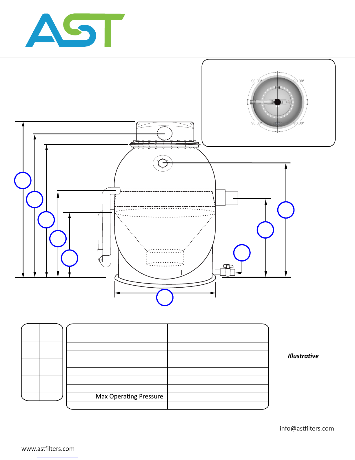
ASTFILTERS.COM
™
HPPG-1OO SPECIFICATIONS
Suflow rotometer are required to regulate the air flow from
the air pump. The air injected into the system regulates the
backwash frequency. These suflow kits are included with the
purchase of the filter.
Overall Height
Outlet
Flange
A
Trigger High
B
Trigger Low
C
STANDARD ORIENTATION
Trigger Low
Custom Orienta�on available.
Inlet
Outlet
Trigger High
Window
Window
Emergency
Drain
and Inlet
H
F
D
Sludge
Drain
I
E
G
Overall Diameter
~150”
A
~141”
B
134”
C
76.5”
D
56.5”
E
82.5”
F
84”
G
112”
H
~5”
I
Std. Motor HP : air pump type
Max Flow Rate
3
Ft
of Enhanced Media
2
Ft
of Surface Area
Inlet Coupling
Outlet Pipe
Sludge Drain Valve
Inlet Valve
Shipping Weight
1/3 HP: piston compressor
1000 -1500 gpm
100
40000
12”
(2x) 10”
3” Fip
12” Fipt
20 PSI
~6100 Lbs
Filter shown for
Purposes only.
Drawing is NOT
drawn to scale.
AST Aquaculture Systems Technologies, LLC
108 Industrial Avenue
New Orleans, LA 70121
Phone: 504.837.5575
Toll-Free:800.939.3659
Fax: 504.837.5585
 Loading...