

Page 1
Switching amplifier
BS 805
Original
Manual
Strain gauge switching amplifier BS 805.01 / BS 805.11 / BS 805.21
A.S.T. Angewandte SYSTEM-TECHNIK GmbH Dresden
Marschnerstraße 26 01307 Dresden
phone (03 51) 44 55 30 fax (03 51) 44 55 555
www.ast.de vertrieb.dd@ast.de
1
Page 2

Page 3

Manual switching amplifier BS 805
Index of contents
1. Safety Instructions ............................................................................................................................... 1
2. Wiring Diagram ..................................................................................................................................... 2
3. Operating elements .............................................................................................................................. 2
3.1. Adjustments ........................................................................................................................................ 4
3.2. Button .................................................................................................................................................. 4
4. LED- display .......................................................................................................................................... 4
5. Function of key T1 ............................................................................................................................... 5
5.1. Code table ........................................................................................................................................... 5
5.2. Example .............................................................................................................................................. 6
6. Information on Performance-Level PLc in accordance with DIN EN 13849-1 ............................... 6
6.1. Classification of Type Series “Switching Amplifier BS 805” ................................................................ 6
6.2. Error detection in operation with a connected sensor ........................................................................ 6
6.3. Other functions .................................................................................................................................... 7
7. Commissioning .................................................................................................................................... 7
7.1. Mounting ............................................................................................................................................. 7
7.2. Connection .......................................................................................................................................... 7
7.3. Signal settings ..................................................................................................................................... 8
7.4. Control of settings ............................................................................................................................... 9
8. Specification ....................................................................................................................................... 10
9. EC Declaration of Conformity ........................................................................................................... 11
Subject to technical change 10/2017 1
A.S.T. Angewandte SYSTEM-TECHNIK GmbH Dresden
Page 4

Page 5
Manual switching amplifier BS 805
1. Safety Instructions
ATTENTION!
ATTENTION!
Any non-compliance with these safety precautions may result in severe damage to property and health!.
ATTENTION!
These Operating Instructions explain the installation, bringing into service, and operation of the type BS
805.0x amplifier. It is assumed that every action is taken by qualified staff only who have adequate
knowledge in the fields of measuring and control engineering.
The equipment must be installed and attached under adherence to of the current DIN and VDE
standards.
The type BS 805.01 Strain-Gauge amplifier has been designed to the purpose of amplifying the output
signals of sensors with metal-foil strain gauges, preferably force transducers.
The type BS 805.02 has been designed to the purpose of amplifying the output signals of sensors with
standard signal 4-20mA, preferably force transducers.
Any other application is regarded contrary to intended usage.
The BS 805.0x may not be used as exclusive means for the prevention of dangerous conditions at
machines and plants.
Make sure that any erroneous setting or malfunction of the unit or its break-down cannot cause damage
or be a risk to the staff or other persons.
Subject to technical change 10/2017 Page 1 of 12
A.S.T. Angewandte SYSTEM-TECHNIK GmbH Dresden
Page 6
Manual switching amplifier BS 805
V
2
V
2
6
2. Wiring Diagram
BS 805.01 / BS 805.21
Force transducer
-X1
+SI+EX
-SI-EX
Standard signal output
A
Power supply
+EX
-EX
+SI
4-20mA
0mA
10-30VDC
GND
-SI
1
2
3
4
5
6
7
8
µC
-X10
SP1
T1
0
T1
?t
1
SP2
1
1NC1
2COM1
3NO1
-X12
1PE1
2PE2
-X11
1NC2
2COM
3NO2
BS 805.11
Force transduce r
-X1
+SI+EX
-SI-EX
A
Standard signal output
Power supply 230VAC
+EX
-EX
+SI
-SI
4-20mA
0mA
L
N
PE
-X5
1
2
3
4
5
6
7
8
1
2
3
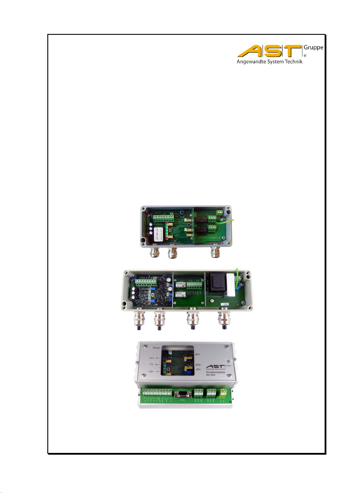
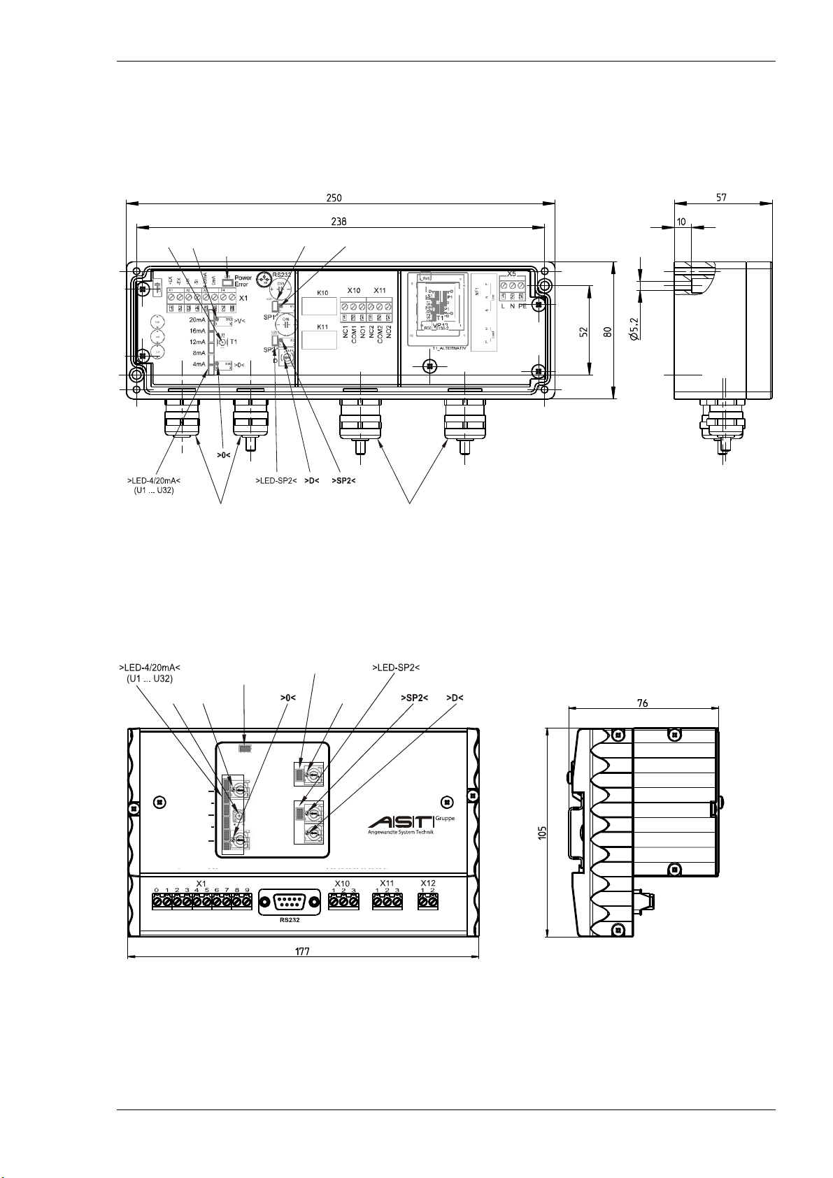
3. Operating elements
BS 805.01 Strain gauge switching amplifier
Supply voltage 10…30VDC / case IP65 – die cast
µC T1
0
T1?t
SP1
SP2
-X10
1NC1
1
1
2COM1
3NO1
-X12
1PE1
2PE2
-X11
1NC2
2COM
3NO2
>V<>T1<
Cable gland M16
D = 5 … 10mm
>LED-i.O.<
(U78)
>LED-SP1<
>SP1<
Cable gland M20
… 12mm
D =
Page 2 of 12 Subject to technical change 10/2017
A.S.T. Angewandte SYSTEM-TECHNIK GmbH Dresden
Page 7
Manual switching amplifier BS 805
m
m
BS 805.11 Strain gauge switching amplifier
Supply voltage 230VAC /case IP65 – die cast
>V<>T1<
>LED-i.O.<
(U78)
Setup
>LED-SP1<
>SP1<
Cable gland M16
D = 5 … 10m
Cable gland M20
D = 6 … 12m
BS 805.21 Strain gauge switching amplifier
Supply voltage 10…30VDC / case IP40 – DIN rail
>V<
>0<
SH
+EX
Power
T1
-EX
>V<>T1<
+SI
20
mA
4
-SI
4-20
>LED-i.O.<
(U78)
-
+
24V
mA
0mA
SH
>LED-SP1<
>SP1<
SP1
SP2
>D<
NC1
COM1
Schaltverstärker
BS 805
NC2
NO1
NO2
PE
COM2
PE
Subject to technical change. 10/2017 Page 3 of 12
A.S.T. Angewandte SYSTEM-TECHNIK GmbH Dresden
Page 8

Manual switching amplifier BS 805
3.1. Adjustments
Switch Function
>V< 16 mA - characteristic value setting 0,8 … 2,5mV/V
>0< 4mA - setting to zero point -0,5 … +0,5mV/V
SP1 Switching point setting/ switching range 4....20mA
SP2 Switching point setting/ switching range 4....20mA
D Switching delay for SP2 0 ... 5sec.
Strain gauge switching amplifier
BS 805.01
BS 805.11
BS 805.21
3.2. Button
Switch
T1 Additionally function see Point 5
Function
4. LED- display
LED Normal operations Error (flashing display)
U1 <4mA incorrect code enter
U2 4mA < I < 8mA
U4 8mA < I < 12mA -
U8 12mA < I < 16mA U16 16mA < I < 20mA U32 20mA < I U78 Ready for operation break or short in sensor wire
U21 SP1 current on U22 SP2 current on -
blinks once Current level exceeded through +EX
for BS805.y1 bridge resistance < 300
for BS805.y1 sensor current > 40mA
blinks twice Current level not attained through +EX
Only for BS805.y1 bridge resistance > 1000
blinks 3 times Input signal exceeded
for BS805.y1 bridge signal = > +2.5mV
blinks 4 times Input signal not attained
for BS805.y1 bridge signal < -2.5mV/V
blinks 5 times Bridge median voltage exceeded
only for BS805.y1 (–SI zu –EX >2.2V)
blinks 6 times Bridge median voltage not attained
only for BS805.y1(–SI zu –EX <1.2V)
Page 4 of 12 Subject to technical change 10/2017
A.S.T. Angewandte SYSTEM-TECHNIK GmbH Dresden
Page 9

Manual switching amplifier BS 805
5. Function of key T1
5.1. Code table
Element Function Code
Relay 1 Normal from
appointed SP1
current less
Inverse from
appointed SP1
current on
Hysterese 0,0mA 230
Hysterese 0,1mA 231
Hysterese 0,5mA 232
Hysterese 1,0mA 233
Hysterese 2,0mA 234
Relay 2 Normal from
appointed SP2
current less
Inverse from
appointed SP2
current on
Hysterese 0,0mA 240
Hysterese 0,1mA 241
Hysterese 0,5mA 242
Hysterese 1,0mA 243
Hysterese 2,0mA 244
Mandatory security
SP1
Relay 1 and Relay 2 Reset at normal 255
Constant current 4,0 311
(mA) 12,0 312
20,0 313
+ 0,2 344
+ 0,5 343
+ 1,0 331
+ 2,0 332
+ 3,0 333
+ 4,0 334
+ 5,0 335
- 0,2 341
- 0,5 342
- 1,0 321
- 2,0 322
- 3,0 323
- 4,0 324
- 5,0 325
Example 16,8=12,0+5,0-0,2 “312”+”335
Current to reset Back to measuring
Subject to technical change. 10/2017 Page 5 of 12
A.S.T. Angewandte SYSTEM-TECHNIK GmbH Dresden
Switching attitude
SP1, SP2: normal,
adjustment SP1: to
2mA over SP2,
fault: SP1 and SP2
current less and
output signal 2mA
mode
211
212
221
222
251
”+”341”
355 or
voltage
supply 10–
30VDC to
break
Element Function Code
Basic setting
(only BS 805.01 )
Setup-protection on 421
off 425
Strain gauge input tension and
Negative 412
Positive 415
Test signal on 422
off 423
>V< - limit stop left ∆16mA = ∆2,0mV/V 431
∆16mA = ∆1,5mV/V 432
∆16mA = ∆1,0mV/V 433
∆16mA = ∆2,5mV/V 435
>V< - limit stop right ∆16mA = ∆0,5mV/V 441
∆16mA = ∆1,0mV/V 442
∆16mA = ∆1,5mV/V 443
∆16mA = ∆0,83mV/V 445
>0< - adjusting range - 1,00 ... 0,00mV/V 451
- 0,75 ... +0,25mV/V 452
- 0,25 ... +0,75mV/V 453
0,00 ... +1,00mV/V 454
- 0,50 ... +0,50mV/V 455
SP1: normal / without
hysteresis
SP2: normal / without
hysteresis
Strain gauge input
positive
Zero point -/+ 0,5
mV/V
compression:
12mA=0mV/V
555
411
Page 10

Manual switching amplifier BS 805
R
d
e
5.2. Example
sequence Operation for Code 341 LED-display
1.
3-times press >T1<
>U2-U4-U8< light
2. Wait approx. 2 sec Light off
3.
4-times press >T1<
>U2-U4-U8-U16< light
4. Wait approx. 2 sec Light off
5.
1-times press>T1<
>U2< light
6. end LED >U16< flashing approx. 2 sec
6. Information on Performance-Level PLc in accordance with DIN EN 13849-1
6.1. Classification of Type Series “Switching Amplifier BS 805”
The Switching Amplifier BS805 can be classified in the Performance-Level PLc in accordance with the set of
standards governing Safety Relevant Control Systems DIN EN 13849-1.
This then covers hazards as shown in the hazard graphs below recommended for safety-relevant control systems in
conjunction with the Performance-Level PLc and SK1 Category.
Severity of injury (S)
S1 Slight injury (usually temporary)
S2 Severe injury (usually irreversible),
including death
Frequency and/or duration of exposure to
hazard (F)
F1 ... Seldom to quite often and/or short
duration of exposure
F2 ... Frequent to permanent and/or short
duration of exposure
Possibility of preventing the hazard (P)
P1 ... Possible under certain conditions
P2 ... Hardly possible
Starting
point for
assessing
risk
reduction
equire
Low
risk
performanc
level PL
a
P
1
F
S
1
F
2
1
P
2
b
P
1
P
2
c
P
F
1
S
2
F
2
1
P
2
d
P
1
P
2
e
High
risk
6.2. Error detection in operation with a connected sensor
The Switching Amplifier BS805 identifies the following errors:
Sensor monitoring
- Wire breakage, also on single core of sensor cable.
- Short circuit on any number of cores of sensor cable.
- “Unsafe” connection of individual cores.
Internal monitoring
- Failure of operating voltage
- Failure of sensor power supply
The BS 805 is responding to an error with:
- Relay SP1 and SP2 fall (to drop out)
- LED U78 blinking
- Output signal is 2mA
Page 6 of 12 Subject to technical change 10/2017
A.S.T. Angewandte SYSTEM-TECHNIK GmbH Dresden
Page 11

Manual switching amplifier BS 805
6.3. Other functions
In the event of a software error occurring, the inherent processor watchdog will repeatedly attempt to restart the
Switching Amplifier BS805, this involving constant opening/closing of the relays SP1 and SP2.
Zero drifts on the internal amplifier are cyclically corrected.
The function of the Switching Amplifier BS805 is not impaired by errors occurring on downstream devices.
Coercive fusing of relay SP2 can be set by means of key code ‘251’ as follows: SP1 lies 0…2mA above SP2.
Accordingly, SP1 monitors SP2 (the latter normally being set with a time lag) and is immediately de-energised
whenever a short and high load peak occurs
7. Commissioning
7.1. Mounting
The BS 805.01 and BS 805.11 appliances are intended to be wall-mounted using two M5 screws. The drilling patterns
for BS 805.01 (163 x 52) and BS 805.11 (238x52) will be found under 3.
Appliances BS 805.21 are designed for mounting on a standard rail.
7.2. Connection
Excitation voltage + + EX
Excitation voltage - -EX
Signal + + SI
Signal - - SI
Analogue Output 4…20mA
Analogue Output 0 mA
Shield SHI
Power supply 10-30VDC
Power supply GND
230VAC L
N
PE
PE
PE
Rel. 1 NC
Com
NO
Rel. 2 NC
Com
NO
BS 805.01 BS 805.11 BS 805.21
X1/1
X1/2
X1/3
X1/4
X1/5
X1/6
cable gland cable gland X1/0
X1/9
X1/7 - X1/7
X1/8 - X1/8
- X5/1 -
- X5/2 -
- X5/3 X12/1
X12/2
X10/1
X10/2
X10/3
X11/1
X11/2
X11/3
The cables for the sensor, the supply voltage and the signal output are to the strip_X1: to attach. Protective
conductors of the discharges for the switching signals are to be attached absolutely to the strip_X12: PE
Standard contacting of cable shield to contact clip
cable jacket and shield dismantle
cut around the cable jacket 15mm behind the end, do not remove however yet
pass through the cable
cable jacket removal
draw back the cable until the connection between cable shield and contact clip is existent
tighten
Contacting of cable shield with thin cables without cable sheath:
cable jacket dismantle
roll up the shield over the cable jacket approx.15 - 20 mm
pass through the cable until the connection between cable shield and contact clip is existent
tighten
Subject to technical change. 10/2017 Page 7 of 12
A.S.T. Angewandte SYSTEM-TECHNIK GmbH Dresden
Page 12

Manual switching amplifier BS 805
7.3. Signal settings
With the aid of an ammeter and/or LED corresponding to Section 4, the zero point is set by means of the >0<
adjuster, the load value for sensor loading being set using the >V< adjuster.
Setting the zero point with the >0< adjuster
- De-charge the sensor.
- The zero point 4mA is correctly set at the very point where the red LED just about lights up.
- Output current below 4mA: Turn >0< adjuster clockwise,
- Red LED remains on: Extend zeroing range in minus
direction applying functions 452 or 451
Setting the load value using the >V< adjuster
- Charge the sensor.
- The load value, e.g. 20mA is correctly at the point where the red LED does not yet light up.
- Output current below 20mA: Turn >0< adjuster
clockwise,
- Red LED remains off: Extend zeroing range with
functions 44x
Whenever the appliance detects an error (refer to point 4 LED display, LED U78) an output current of 2mA is always
generated and the red LED >U1< lights up.
A note can be made of the test signal (Code No.: Switch-on 422, Switch-off 423) for documentation purposes later on.
For this purpose de-charge the sensor, measure the output signal and connect the test signal by means of function
422. Now measure the output signal and switch the test signal back off again by means of function 423. A note is
made of the difference between the output signals which can then be reviewed when checks are carried out at a later
point.
Setting the switching points >SP1< and >SP2<
Setting of the switching points with the aid of the rotary potentiometers SP1 and SP2 governing the relays takes place
applying the corresponding test loads or, if proceeding from a computed current signal, by means of the constantcurrent settings (Code No. 311 to 355).
The switching action of the relays needs to be set as required using key >T1< (Code No. 211 to 255).
After being connected, the sensor is charged with a test load. If the test load cannot be attained or no constant setting
is possible, an alternative in lieu of this is to set a constant current applying the functions 31x
Page 8 of 12 Subject to technical change 10/2017
A.S.T. Angewandte SYSTEM-TECHNIK GmbH Dresden
- Output current exceeds 4mA: Turn >0< adjuster counter clockwise,
- Green LED remains on: Extend zeroing range in plus
direction applying functions 453 or 454
- Output current exceeds 20mA: Turn >V< adjuster
counter-clockwise,
- Red LED remains on: Extend zeroing range with
functions 43x
Page 13

Manual switching amplifier BS 805
Example
- Cut-off point 1 14mA is intended to switch >SP1<:
- Call function 312 and function 332 (output current now 12mA + 2mA = 14mA)
- Turn >SP1< adjuster clockwise up to the very point where relay 1 just about switches over.
- Cut-off point 2 8mA is intended to switch >SP2<:
- Call function 334 (output current now 14mA + 4mA = 18mA)
- Turn >SP2< adjuster clockwise up to the very point where relay 2 just about switches over.
- Switch to measuring mode applying function 355.
When geared to the standard setting, the relay de-energises as soon as the switching point is attained. The function
2x2 reverses the switching action and allows the relay to energise when the switching point is attained.
7.4. Control of settings
The signal and switching attitude of the BS 805,01 are to be proven at the latest for the delivery of the plant to the
operator at material load cycles.
Protect the setup adjustments with key >T1< (Code-Nr. locking-421 and unlocking-425).
Subject to technical change. 10/2017 Page 9 of 12
A.S.T. Angewandte SYSTEM-TECHNIK GmbH Dresden
Page 14

Manual switching amplifier BS 805
8. Specification
BS 805.01
BS 805.11
BS 805.21
Input
Input signal range
Resistance of strain-gauge bridge
Excitation voltage for sensor
Input resistance
Output
Output signal
Display
Zero point range >0< 4mA
Full load range >V< 20mA
Constant current adjustable
Max. load resistor
Output Relays >SP1< / Relays >SP2<
Switching point adjustable
Switching hysteresis adjustable with >T1<
Switching delay >D< during overstepping
Switching voltage / switching current
Normal / Invers with. >T1<
Accuracy
Reproducibility the settings
Linear error plus hysteresis
Temperature effect full load 20mA
Temperature effect zero 4mA
Power supply
- - Nominal voltage
- - Current consumption
Environmental conditions
Operating temperature range °C -25 ... +60
storage temperature range
Noise immunity
Emitted interference
Oscillating resistance DIN EN 60068-2-6
Shock resistance DIN EN 60068-2-27/-29
Construction
Dimensions (B x H x T)
Environmental protection
admissible conductor cross-section
protective earthing
1) Setting adjustable – 1mV/V to +1mV/V – via key functions 45x.
2) Setting adjustable – 0.5mV/V to 2.5mV/V – via key functions 43x und 44x.
V
mA
mA
mA
mA
Sec
%v. E.
%v. E.
%v.E./10K
%v.E./10K
A
°C -40 ... +70
mm
EN 60529
2
mm
IP65 for BS805.01 and BS805.11/ IP40 for BS805.21
LED-display for Switching status
(10 ... 30)VDC
see measurements in drawings
-2.5 ... +2.4mV/V
350 … 1000
6 LED – display on 4mA-Steps
+/- 0.5mV/V
0.8 ... 2.5mV/V
2 ... 22
0.05 – 0.1 – 0.5 – 1 – 2
250V / 6A
- adjustable -
LED-display for stand by
for BS805.01 and BS805.21/
230VAC for BS805.11
max. 0,3A
DIN EN 61000-6-2
DIN EN 55011-B
Aluminum-die cast
0.14 ... 1.5
Protection class 1
ca. 4
-
4 - 20
300
4 ... 22
0 ... 5
0.5
0.2
0.2
0.2
1)
2)
Page 10 of 12 Subject to technical change 10/2017
A.S.T. Angewandte SYSTEM-TECHNIK GmbH Dresden
Page 15
Manual switching amplifier BS 805
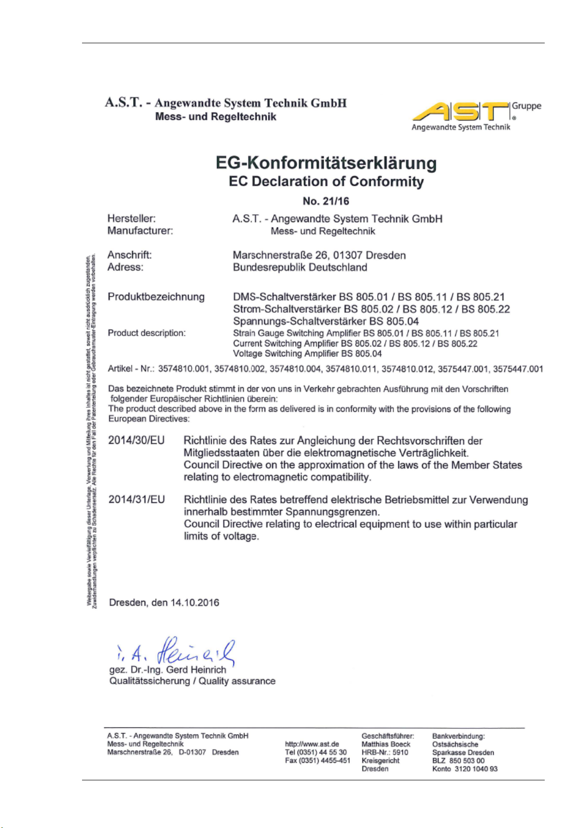
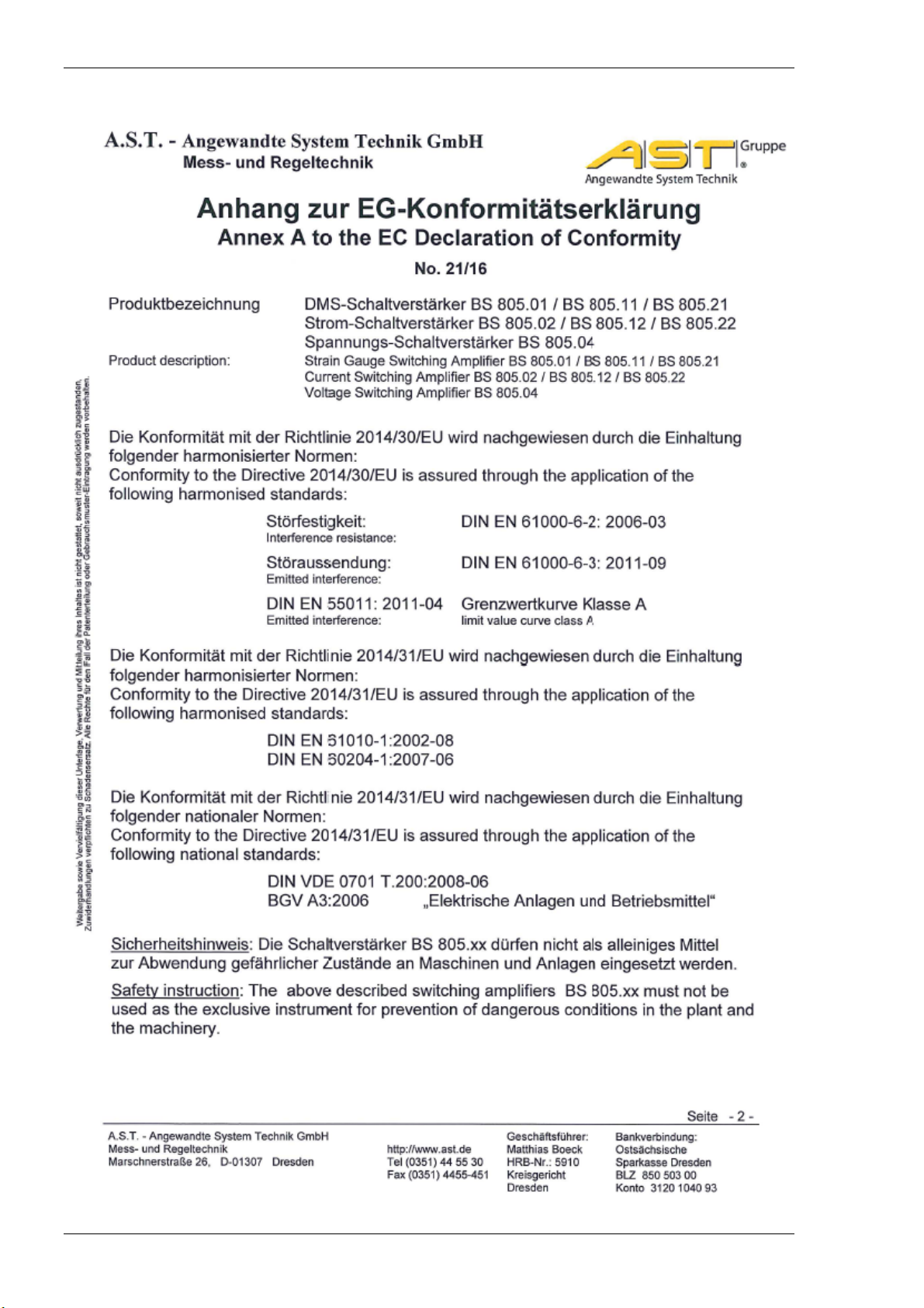
9. EC Declaration of Conformity
Subject to technical change. 10/2017 Page 11 of 12
A.S.T. Angewandte SYSTEM-TECHNIK GmbH Dresden
Page 16
Manual switching amplifier BS 805
Page 12 of 12 Subject to technical change 10/2017
A.S.T. Angewandte SYSTEM-TECHNIK GmbH Dresden
 Loading...