

Page 1
Weighing Controller
A 810
Manual
Rev. 1.10-22
A.S.T. Angewandte SYSTEM-TECHNIK GmbH Dresden
Marschnerstraße 26 01307 Dresden, Germany
Telefon (03 51) 44 55 30 Telefax (03 51) 44 55 555
www.ast.de
Page 2

Page 3

Thank You!
Thank you for purchase A.S.T. products!
SAFETY PRECAUTION
The integrated circuits used in this equipment are highly immune to noise and RFI when properly installed
in the unit.
The terminal on the rear panel must be grounded directly, not with the AC ground.
Therefore, when shipping please always use original packing (conductive material) for shiping. Remove
equipment from the shopping container and examine the external surfaces of the equipment for physical
damage.
The A 810 should be positioned in a safe area with no combustible gas, the operating temperature is
+14°F to 104°F (-10°C to +40°C), storage temperature -28°F to 185°F (-20°C to +85°C)
Confirm the AC voltage of all equipment before power-up. The A 810 can operate within a -15% to + 10%
voltage variation.
A.S.T. Angewandte SYSTEM-TECHNIK GmbH Dresden Page 1
Page 4

Manual of Weighing Controller A 810
Table of contents
DESCRIPTION...................................................................................................................................................7
1.
1.1. FRONT PANEL ................................................................................................................................................7
1.1.1. Numeric Display....................................................................................................................................7
1.1.2. Unit Display ..........................................................................................................................................7
1.1.3. Status display.........................................................................................................................................7
1.1.4. Keypad...................................................................................................................................................9
1.1.5. Rear Panel...........................................................................................................................................10
1.2. PANEL CUT SIZE ...........................................................................................................................................10
2. CONNECTIONS...............................................................................................................................................11
2.1. LOADCELL CONNECTOR...............................................................................................................................11
2.2. PIN- ASSIGNMENT OF CONTROL SIGNAL INPUT / OUTPUT CONNECTOR ......................................................12
2.3. CONTROL INPUT SIGNALS ............................................................................................................................16
2.4. CONTROL OUTPUT SIGNALS.........................................................................................................................19
3. HOW TO GET STARTED...............................................................................................................................21
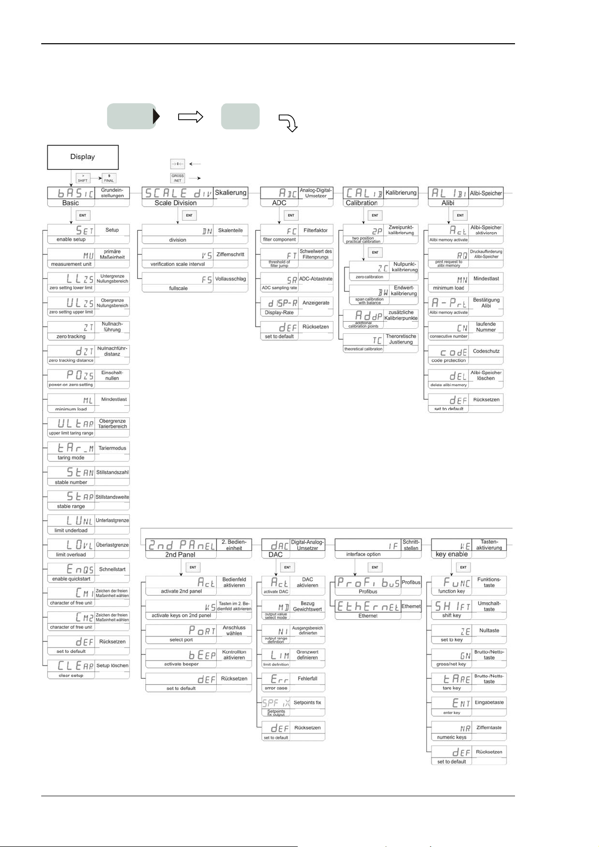
3.1. PARAMETER SETUP SECTION ........................................................................................................................22
3.1.1. Submenu “Basic”................................................................................................................................24
3.1.1.1. Enable Setup “Set”........................................................................................................................................... 24
3.1.1.2. Select primary measurement unit “MU”..........................................................................................................24
3.1.1.3. Range of zero setting lower limit “LLZS”....................................................................................................... 25
3.1.1.4. Range of zero setting upper limit “ULZS”....................................................................................................... 25
3.1.1.5. Zero tracking “ZT” ..........................................................................................................................................25
3.1.1.6. Zero tracking distance “dZT”.......................................................................................................................... 25
3.1.1.7. Power-on zero setting “POZS” ....................................................................................................................... 26
3.1.1.8. Minimum Load “ML”......................................................................................................................................26
3.1.1.9. Upper limit taring range “ULtAR”...................................................................................................................26
3.1.1.10. Taring Mode “tAR_M”................................................................................................................................26
3.1.1.11. Stable number “StAN”............................................................................................................................... 27
3.1.1.12. Stable range “StAR”................................................................................................................................... 27
3.1.1.13. Limit underload “LUNL”........................................................................................................................... 27
3.1.1.14. Limit overload “LOVL”............................................................................................................................. 27
3.1.1.15. Enable quickstart “EnQS”...........................................................................................................................28
3.1.1.16. Select character of free unit “CM1”.............................................................................................................28
3.1.1.17. Select character of free unit “CM2”.............................................................................................................28
3.1.1.18. Set to default “dEF”.....................................................................................................................................29
3.1.1.19. Clear Setup “CLEAR”................................................................................................................................. 29
3.1.2. Submenu “Scale division”...................................................................................................................30
3.1.2.1. Parameter for unit “MU”.................................................................................................................................. 30
3.1.2.1.1. Divisions “DN” ................................................................................................................. ........................ 30
3.1.2.1.2. Verification scale interval “VS”................................................................................................................30
3.1.2.1.3. Fullscale “FS”........................................................................................................................................... 30
3.1.3. Submenu “ADC”.................................................................................................................................32
3.1.3.1. Filter component “FC” .....................................................................................................................................32
3.1.3.2. Threshold of filter jump “FT”.......................................................................................................................... 32
3.1.3.3. ADC sampling rate “SR”.................................................................................................................................32
3.1.3.4. Display Frequency...........................................................................................................................................33
3.1.3.5. Set to default “def”...........................................................................................................................................33
3.1.4. Submenu “Calibration” ......................................................................................................................34
3.1.4.1. Two position practical calibration “2P”........................................................................................................... 34
3.1.4.1.1. Zero calibration “ZC”..............................................................................................................................34
3.1.4.1.2. Span calibration with balance “BW”........................................................................................................ 34
3.1.4.2. Additional calibration points “AddP”..............................................................................................................35
3.1.4.3. Theroretical calibration “TC” .......................................................................................................................... 35
3.1.5. Submenu “Alibi”.................................................................................................................................36
3.1.5.1. Alibi memory activate “Act” ........................................................................................................................... 36
3.1.5.2. Print request to Alibi memory “RQ”................................................................................................................ 36
3.1.5.3. Minimum Load “MN” ..................................................................................................................................... 36
3.1.5.4. Alibi confirmation “A-Prt” ..............................................................................................................................37
3.1.5.5. Consecutive Number “CN”.............................................................................................................................. 37
3.1.5.6. Code protection “code”.................................................................................................................................... 37
3.1.5.7. Delete Alibi memory “dEL”............................................................................................................................ 37
3.1.5.8. Set to default ”dEF”......................................................................................................................................... 38
Page 2 A.S.T. Angewandte SYSTEM-TECHNIK GmbH Dresden
Page 5

Manual of Weighing Controller A 810
3.1.6.
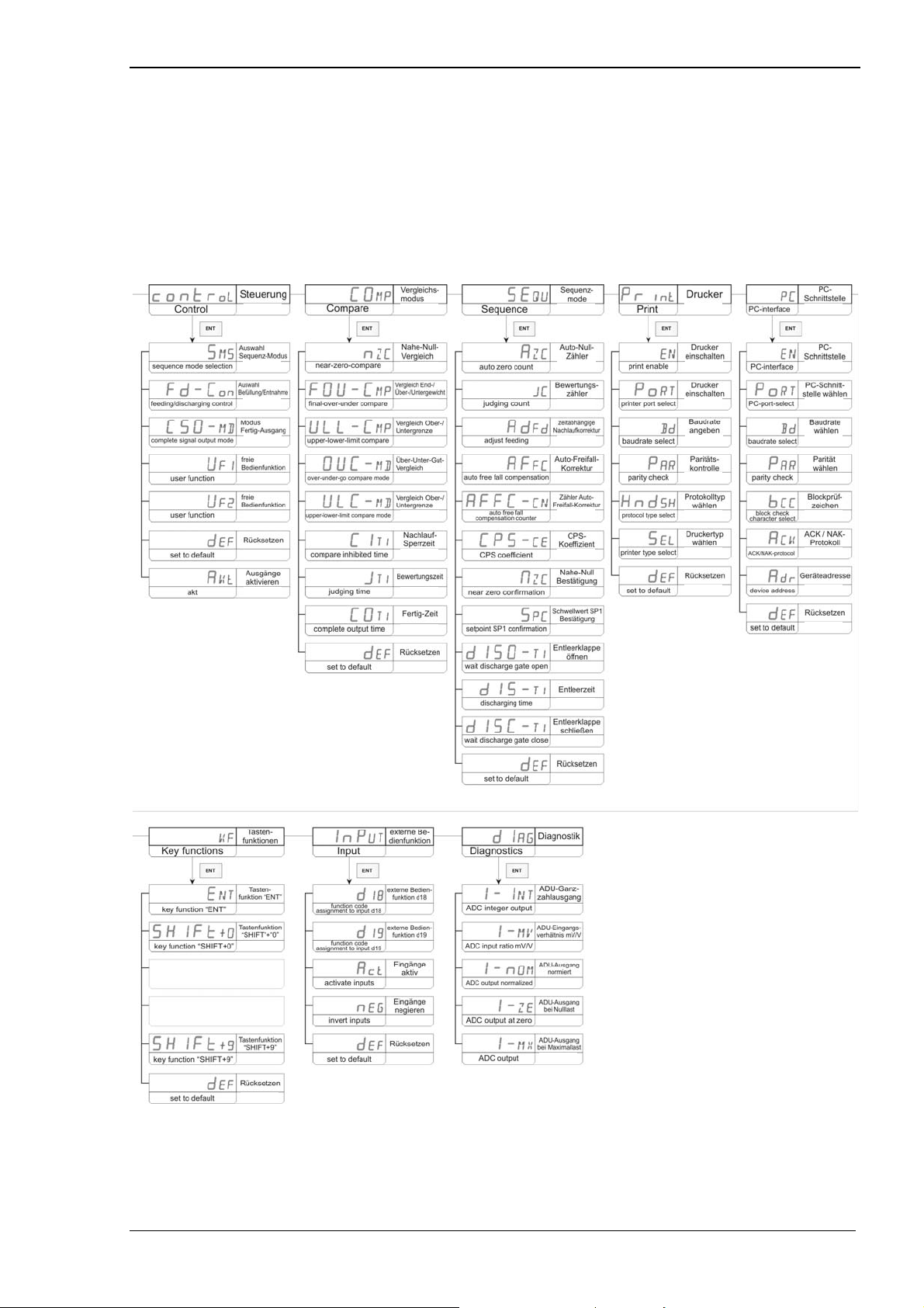
Submenu “Control”.............................................................................................................................39
3.1.6.1. Sequence mode selection “SMS”.....................................................................................................................39
3.1.6.2. Feeding / Discharging control “Fd-Con”..........................................................................................................39
3.1.6.3. Complete signal output mode “CSO-MD”.......................................................................................................39
3.1.6.4. User function “UF1” ........................................................................................................................................40
3.1.6.5. User function “UF2” ........................................................................................................................................40
3.1.6.6. Set to default “dEF” .........................................................................................................................................40
3.1.7. Submenu comparison mode “COMP”................................................................................................41
3.1.7.1. Near-Zero-Compare “nZC”..............................................................................................................................41
3.1.7.2. Final-Over-Under-Compare “FOU-CMP”.......................................................................................................41
3.1.7.3. Upper-Lower-Limit-Compare “ULL-CMP” ....................................................................................................41
3.1.7.4. Over-under-go-compare mode “OUC-MD”.....................................................................................................42
3.1.7.5. Upper-lower-limit-compare mode “ULC-MD”................................................................................................42
3.1.7.6. Compare inhibited time “CITI” ........................................................................................................................42
3.1.7.7. Judging time “JTI” ...........................................................................................................................................42
3.1.7.8. Complete output time “COTI” .........................................................................................................................43
3.1.7.9. Set to default “dEF” .........................................................................................................................................43
3.1.8. Submenu “SEQU”...............................................................................................................................44
3.1.8.1. Auto Zero Count “AZC”..................................................................................................................................44
3.1.8.2. Judging count “JC”...........................................................................................................................................44
3.1.8.3. Adjust feeding “AdFd”.....................................................................................................................................44
3.1.8.4. Auto free fall compensation “AFFC”...............................................................................................................45
3.1.8.5. Auto free fall compensation counter ”AFFC-CN”...........................................................................................45
3.1.8.6. CPS coefficient “CPS-CE”...............................................................................................................................45
3.1.8.7. Near zero confirmation “NZC” ........................................................................................................................45
3.1.8.8. Setpoint SP1 confirmation “SPC”....................................................................................................................46
3.1.8.9. Wait discharge gate open “dISO-TI”................................................................................................................46
3.1.8.10. Discharging time “dIS-TI”...........................................................................................................................46
3.1.8.11. Wait discharge gate close “dISC-TI”...........................................................................................................46
3.1.8.12. Set to default “dEF”.....................................................................................................................................47
3.1.9. Submenu “Print”.................................................................................................................................48
3.1.9.1. Printer enable “EN”..........................................................................................................................................48
3.1.9.2. Printer port select “PoRT”................................................................................................................................48
3.1.9.3. Baudrate select “Bd”........................................................................................................................................48
3.1.9.4. Parity check “PAR”..........................................................................................................................................48
3.1.9.5. Protocol typ select “HndSH”............................................................................................................................49
3.1.9.6. Printer type select “SEL” .................................................................................................................................49
3.1.9.7. Set to default “dEF” .........................................................................................................................................49
3.1.10. Submenu PC-Interface “PC”..............................................................................................................50
3.1.10.1. PC-Interface “EN”.......................................................................................................................................50
3.1.10.2. PC-Port-select “PoRT” ................................................................................................................................50
3.1.10.3. Baudrate select “Bd”....................................................................................................................................50
3.1.10.4. Parity select “PAR”......................................................................................................................................50
3.1.10.5. Block check character select “bCC” ............................................................................................................51
3.1.10.6. ACK / NAK-Protocol “ACK”......................................................................................................................51
3.1.10.7. Device address “Adr” ..................................................................................................................................51
3.1.10.8. Set to default “dEF”.....................................................................................................................................51
3.1.11. Submenu “2nd Panel”.........................................................................................................................52
3.1.11.1. Activate 2nd Panel “Act”.............................................................................................................................52
3.1.11.2. Activate keys on 2nd panel “KS....................................................................................................................52
3.1.11.3. Select “Port” ................................................................................................................................................52
3.1.11.4. Activate beeper “bEEP”...............................................................................................................................52
3.1.11.5. Set to default “dEF”.....................................................................................................................................53
3.1.12. Submenu “dAC”..................................................................................................................................54
3.1.12.1. Activate DAC “Act”....................................................................................................................................54
3.1.12.2. Output value select mode “MD”..................................................................................................................54
3.1.12.3. Output range definition “NI”.......................................................................................................................54
3.1.12.4. Limit definition “LIM”................................................................................................................................55
3.1.12.5. Error case “Err” ...........................................................................................................................................55
3.1.12.6. constant analog output “SPFix”...................................................................................................................55
3.1.12.7. Set to default “dEF”.....................................................................................................................................55
3.1.13. Submenu Interface option “IF”...........................................................................................................57
3.1.13.1. Submenu “Profibus“ ...................................................................................................................................57
3.1.13.1.1. Profibus activate “Act“............................................................................................................................57
3.1.13.1.2. PB-address select “Pb-ADR”..................................................................................................................57
3.1.13.1.3. Set to default “def”..................................................................................................................................57
3.1.13.2. Submenu “Ethernet“ ....................................................................................................................................58
3.1.13.2.1. Ethernet activate “Act“............................................................................................................................58
3.1.13.2.2. TCP/IP-address “IP_ADR“..................................................................................................................... 58
3.1.13.2.3. Subnetmask “Net_M“..............................................................................................................................58
A.S.T. Angewandte SYSTEM-TECHNIK GmbH Dresden Seite 3
Page 6

Manual of Weighing Controller A 810
3.1.13.2.4. Gateway “Gate_W“.................................................................................................................................59
3.1.13.2.5. Set to default “def”..................................................................................................................................59
3.1.14. Submenu Key enable “KE”.................................................................................................................60
3.1.14.1. Function – Key “Func”................................................................................................................................ 60
3.1.14.2. Shift – Key “SHIFT”................................................................................................................................... 60
3.1.14.3. Set – Zero – Key “ZE” ................................................................................................................................ 60
3.1.14.4. Gross / Net – Key “GN”.............................................................................................................................. 60
3.1.14.5. Tare – Key “TA”................................................................................................................ ......................... 61
3.1.14.6. Enter – Key “ENT”......................................................................................................................................61
3.1.14.7. Numeric – Keys “NR”................................................................................................................................. 61
3.1.14.8. Set to default “dEF”.....................................................................................................................................61
3.1.15. Submenu key functions “KF”..............................................................................................................62
3.1.15.1. Key Function “ENT”................................................................................................................................... 62
3.1.15.2. Key Function “Shift+0”...............................................................................................................................62
3.1.15.3. Key Function “Shift+9”...............................................................................................................................62
3.1.15.4. Set to default “dEF”.....................................................................................................................................62
3.1.16. Submenu “Input”.................................................................................................................................64
3.1.16.1. Function code assignment to input D° 18....................................................................................................64
3.1.16.2. Function code assignment to input D° 19....................................................................................................64
3.1.16.3. Activate inputs “Act”...................................................................................................................................64
3.1.16.4. Invert inputs “neg”.......................................................................................................................................64
3.1.16.5. Set to default “dEF”.....................................................................................................................................65
Submenu “Diagnostics”......................................................................................................................................66
3.1.16.6. ADC – Integer output “I - INT”.................................................................................................................66
3.1.16.7. ADC – input ratio mv/V “I – MV”.............................................................................................................. 66
3.1.16.8. ADC – output normalized “I – nOM........................................................................................................... 66
3.1.16.9. ADC – ouput at zero “I – ZE”..................................................................................................................66
3.1.16.10. ADC – output “I – MX”..............................................................................................................................66
3.2. COMBINATION OF “FUNC” AND ANY NUMERIC KEY .....................................................................................67
3.2.1. Reduced setup (0)................................................................................................................................67
3.2.2. Show actaul code (1)...........................................................................................................................67
3.2.3. Activate code / edit codesets (2)..........................................................................................................67
3.2.3.1. Code selection..................................................................................................................................................67
3.2.3.2. Code source select............................................................................................................................................ 67
3.2.3.2.1. Parameter set of code N° 0........................................................................................................................ 68
3.2.3.2.2. Parameter “FINAL” of code N° 0............................................................................................................. 68
3.2.3.2.3. Parameter “Compensation” of code N° 0.................................................................................................. 68
3.2.3.2.4. Constant analog output “CPS out”............................................................................................................ 68
3.2.3.2.5. Parameter “Set Point 2” of code N° 0.......................................................................................................68
3.2.3.2.6. Constant analog output “SP2 out”............................................................................................................. 69
3.2.3.2.7. Parameter “Set Point 1” of code N° 0......................................................................................................69
3.2.3.2.8. Constant analog output “SP1 out”............................................................................................................. 69
3.2.3.2.9. Parameter “Over” of code N° 0................................................................................................................. 70
3.2.3.2.10. Parameter “Under” of code N° 0.............................................................................................................70
3.2.3.2.11. Parameter “Upper” of code N° 0.............................................................................................................70
3.2.3.2.12. Parameter “Lower” of code N° 0................................................................................................. ........... 70
3.2.3.2.13. Parameter “Near Zero” of code N° 0......................................................................................................71
3.2.3.2.14. Parameter “AFFL” of code N° 0............................................................................................................. 71
3.2.3.2.15. Parameter “CFTI” of code N° 0............................................................................................................ 71
3.2.3.3. Parameter set of code N° 1............................................................................................................................... 71
3.2.3.4. Parameter set of code N° 9............................................................................................................................... 71
3.2.4. Show accumulation total sum (3) ........................................................................................................72
3.2.5. Show accumulation count (4)..............................................................................................................72
3.2.6. Clear active accumulated sum (5).......................................................................................................72
3.2.7. Clear all codesets (6)...........................................................................................................................73
3.2.8. Set date and time (7)............................................................................................................................73
3.2.9. Edit Consecutive number (8)...............................................................................................................74
3.2.10. Show higher resolution (9) ..................................................................................................................74
4. SERIAL INTERFACES ...................................................................................................................................75
4.1. MODES OF OPERATION OF THE SERIAL INTERFACES ....................................................................................75
4.2. EXCHANGE OF A CHARACTER ......................................................................................................................75
4.2.1. Data Exchange Parameters.................................................................................................................75
4.2.2. Character Coding................................................................................................................................75
4.2.3. Electrical Implementation of the Serial Interfaces..............................................................................75
4.2.4. Physical Protocol (Handshake)...........................................................................................................76
4.2.5. Logical Devices...................................................................................................................................76
Page 4 A.S.T. Angewandte SYSTEM-TECHNIK GmbH Dresden
Page 7

Manual of Weighing Controller A 810
4.3.
PRINTERS .....................................................................................................................................................76
4.4. REMOTE DISPLAY UNITS..............................................................................................................................76
4.4.1. A810 Remote Display Units.................................................................................................................76
4.4.2. Foreign Remote Display Units ............................................................................................................77
4.5. PC / SPC......................................................................................................................................................77
4.5.1. Acknowledgement Protocol.................................................................................................................77
4.5.2. Structure of a Data Frame...................................................................................................................77
4.5.3. Remote Control Commands.................................................................................................................77
4.5.3.1. Keyboard Commands.......................................................................................................................................78
4.5.3.2. Commands for Weighing Operations...............................................................................................................79
4.5.3.3. Commands for Printer Output ..........................................................................................................................82
4.5.3.4. Commands for Data Protocol...........................................................................................................................84
4.5.3.5. Miscellaneous Command .................................................................................................................................85
4.5.4. Behaviour in case of trouble................................................................................................................86
4.6. EXAMPLES OF COMMUNICATION INTERFACES .............................................................................................87
4.6.1. RS-485 Interface..................................................................................................................................87
4.6.2. RS-232 Interface..................................................................................................................................88
4.7. TABLES OF SERIAL INTERFACES....................................................................................................................89
4.7.1. Commands of the PC Interface............................................................................................................89
4.7.2. Code-Table A810 Keyboard................................................................................................................90
5. SPECIFICATIONS...........................................................................................................................................91
5.1. INTERFACE ...................................................................................................................................................92
5.2. FEATURES / BASIC FUNCTIONS .....................................................................................................................92
5.3. CALIBRATION LOCK.....................................................................................................................................93
6. APPLICATION NOTES...................................................................................................................................94
6.1. CALIBRATION PROCEDURE ...........................................................................................................................94
6.2. THEORETICAL CALIBRATION ........................................................................................................................96
6.3. SIMPLE COMPARISON MODE – FEEDING WEIGHING E.G. 1...........................................................................97
6.4. SIMPLE COMPARISON MODE – FEEDING WEIGHING E.G. 2...........................................................................99
6.5. SIMPLE COMPARISON MODE – DISCHARGING WEIGHING ..........................................................................101
6.6. SEQUENCE MODE.......................................................................................................................................103
6.7. SEQUENCE MODE WITHOUT JUDGEMENT ...................................................................................................105
6.8. SEQUENCE MODE WITH ADJUST FEEDING ..................................................................................................106
6.9. AUTO FREE FALL COMPENSATION .............................................................................................................107
7. APPENDIX ......................................................................................................................................................108
7.1. ASCII-TABLE.............................................................................................................................................108
7.2. SURVEY OF OPERATING FUNCTIONS ..........................................................................................................109
7.3. DESCRIPTION OF STATES OF ERROR ...........................................................................................................112
A.S.T. Angewandte SYSTEM-TECHNIK GmbH Dresden Seite 5
Page 8

Manual of Weighing Controller A 810
0 History
1.10.22 (May 11): signal output B21 used in sequence-mode; generation of Err109 due to
missing confirmation signal at input pins D18 or D19 (with user function
“230” associated); detailed description of signal input D18/19 at page 65;
change of picture “PC-Interface” at page 88; new parameter “SPFix” in
menu “DAC” for constant analog output at setpoints SP1, SP2 and CPS
1.10-21 (November 10): Interface: USB as option
1.10-20 (September 10): graphics of frontdesign and rear-panel changed due to constructive
reasons
1.10-19 (January 10): due to change of processor, sample rate of 400/s is selectable
(Firmware-Version V.32)
1.10-18 (June 09): due to Firmware-Update to V.31 default parameter dISP-R changed
(faster display rate)
1.10-17 (June 09): due to Firmware-Update to V.30 parameter dISP-R added (display rate
selectable)
1.10-16 (May 08): description Err 129 added
1.10-15 (March 08): refresh rate of I/O added
1.10-14 (January 08): additional operating functions added
1.10-13 (November 07): description of “dAC” changed
Page 6 A.S.T. Angewandte SYSTEM-TECHNIK GmbH Dresden
Page 9
Manual of Weighing Controller A 810
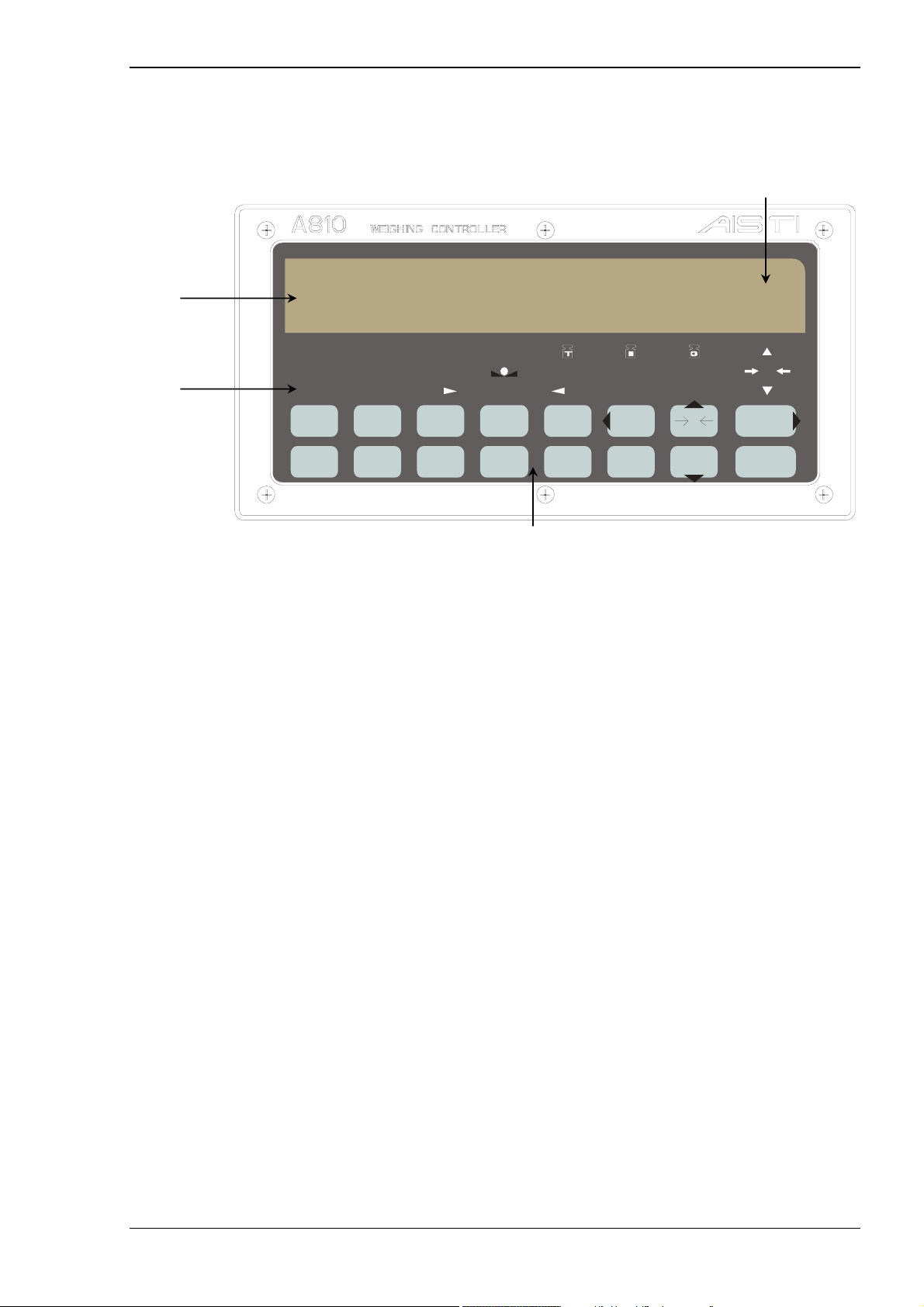
1. Description
1.1. Front Panel
Numeric display
Unit display
Status display
SP3
KEY ZT ZALM TARE NET GROSS 0
HOLD LO LIM LO GO HI HI LIM NZ
1
UPPER
6
LOWER
SP2 SP1 STAB
23
OVER NEAR Z
78
UNDER FINAL
SP1
9
CPS
Keypad
54
SP2
0
USER
0
TAR E ENT
GROSS
/NET
SHIFTFUNC
The front panel contains a 7 digit numeric display, a two digit alphanumeric display, a multiple status
display and 16 key membrane pad.
Legal-for-trade weighing parameter information is available in a separate window (Descriptive marking).
1.1.1. Numeric Display
The seven digit large size display allows showing a six digit weighing value and an additional plus / minus
character. This display is used for weighing values like Gross, Net, Tare, accumulation values and setup
values as well as Error messages.
1.1.2. Unit Display
This two digit unit display is used for units in weighing mode and for alphanumeric information in setting
mode.
1.1.3. Status display
SP3 : Turns on, if the weighing value has reached “FINAL” – “CPS” and the desired output
signal at the rear panel is active on.
SP2 : Turns on, if the weighing value has reached “FINAL” - “SetPoint2” and the desired
output signal at the rear panel is active on.
SP1 : Turns on, if the weighing value has reached “FINAL” - “SetPoint1” and the desired
output signal at the rear panel is active on.
KEY : Turns on, if the calibration lock is enabled.
ZT : Turns on, if zero tracking is in operation.
ZALM : Starts flashing if zero drift exceeds the Digital Zero limit.
A.S.T. Angewandte SYSTEM-TECHNIK GmbH Dresden Seite 7
Page 10

Manual of Weighing Controller A 810
0
STAB
: Turns on, if weighing value is stable.
: Turns on, if Tare weight is displayed.
TARE : “TARE” turns on, if Tare subtraction is active and Tare has a content.
NET : Turns on, if Net weight is displayed.
GROSS : Turns on, if Gross weight is displayed.
HI LIM : Turns on, if upper limit has been reached and the desired output signal at the rear panel
is active on.
HI : Turns on, if “weighing_value” > “FINAL” + “OVER”.
GO : Turns on, if ”FINAL” - “UNDER” ≤ “weighing_value” ≤ “FINAL” + “OVER”.
LO : Turns on, if “weighing_value” < “FINAL” - “UNDER”.
LO LIM : Turns on, if lower limit has been reached and the desired output signal at the rear panel
is active on.
HOLD : Turns on, if weighing display is held.
NZ : Turns on, if “weighing_value” ≤ “Near_Zero”.
: Turns on, if weighing value is at +1/4 scale division.
: Turns on, if weighing value is at centre zero.
: Turns on, if weighing value is at -1/4 scale division.
Page 8 A.S.T. Angewandte SYSTEM-TECHNIK GmbH Dresden
Page 11
Manual of Weighing Controller A 810
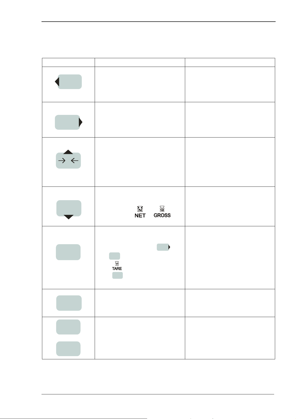
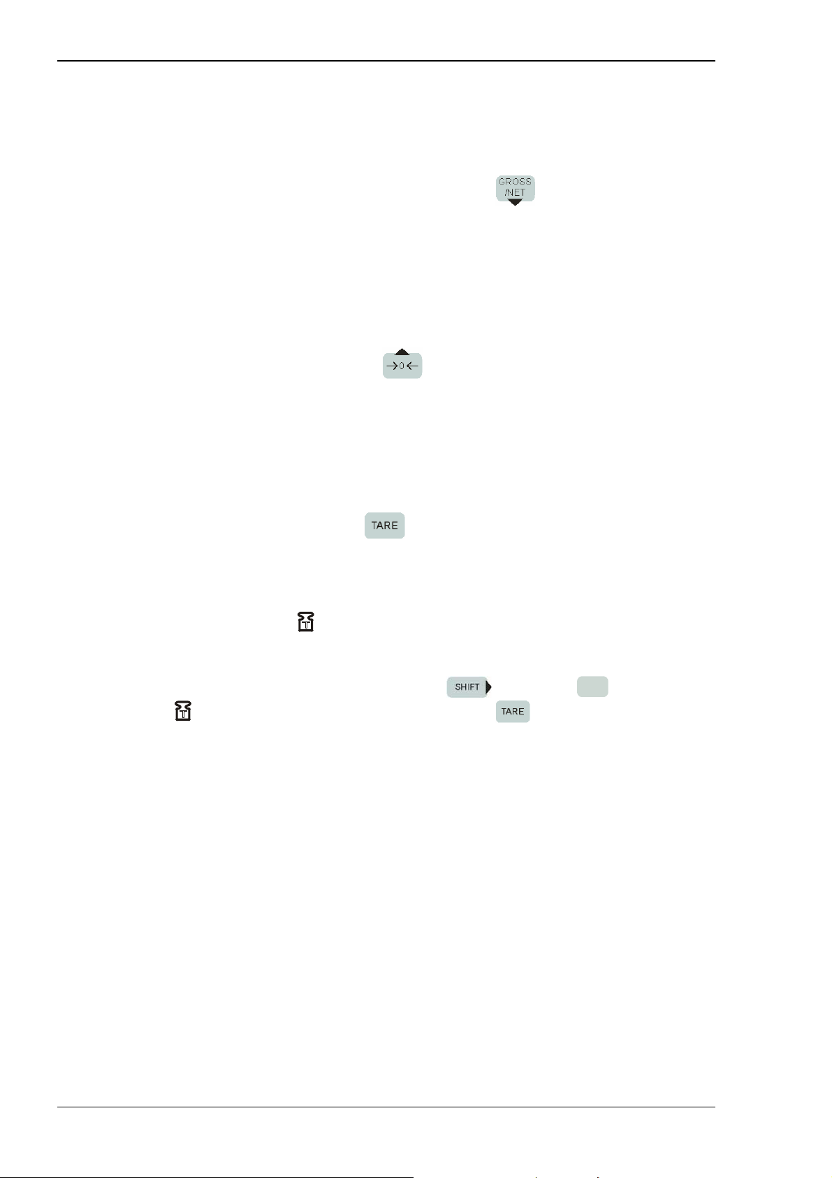
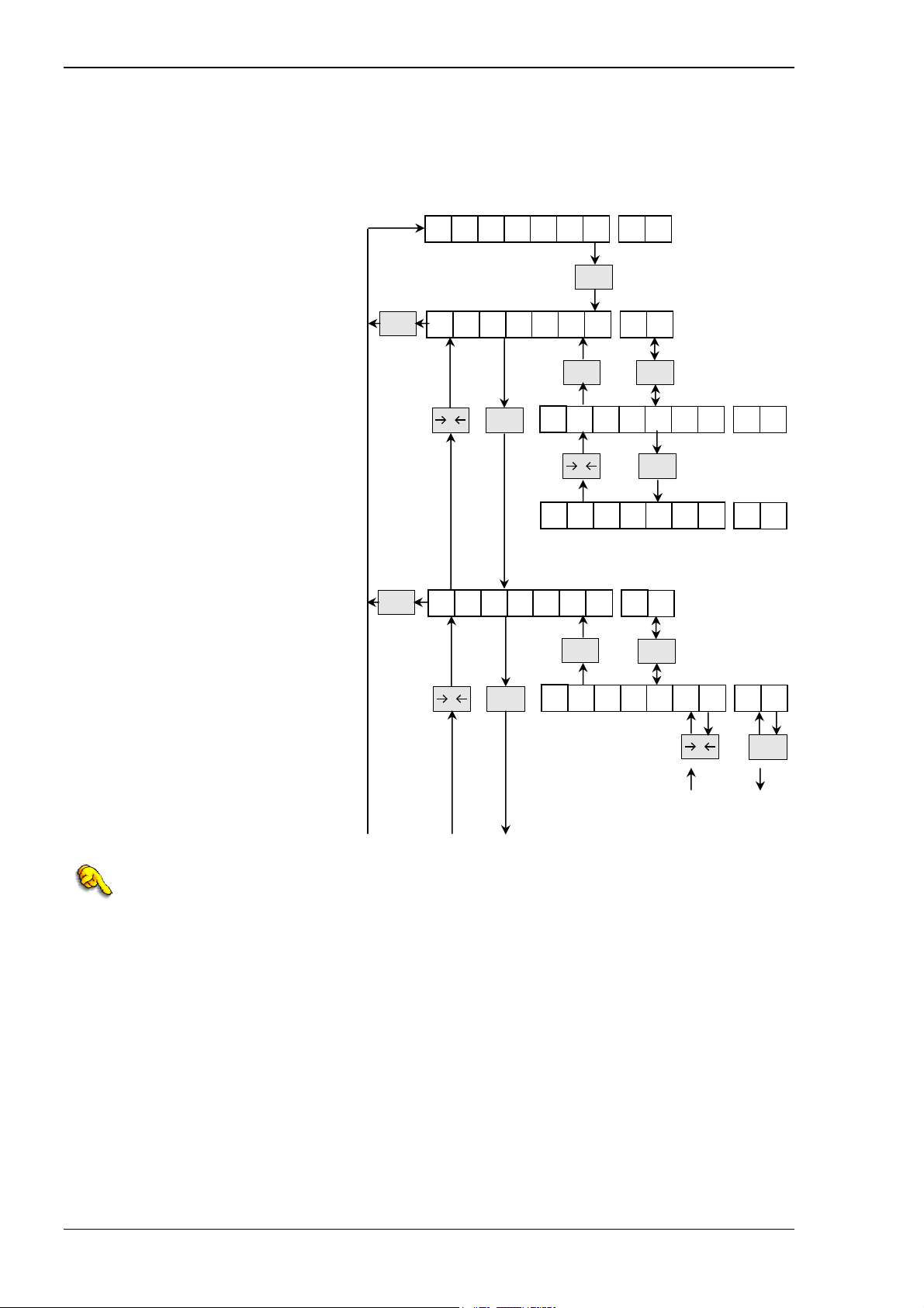
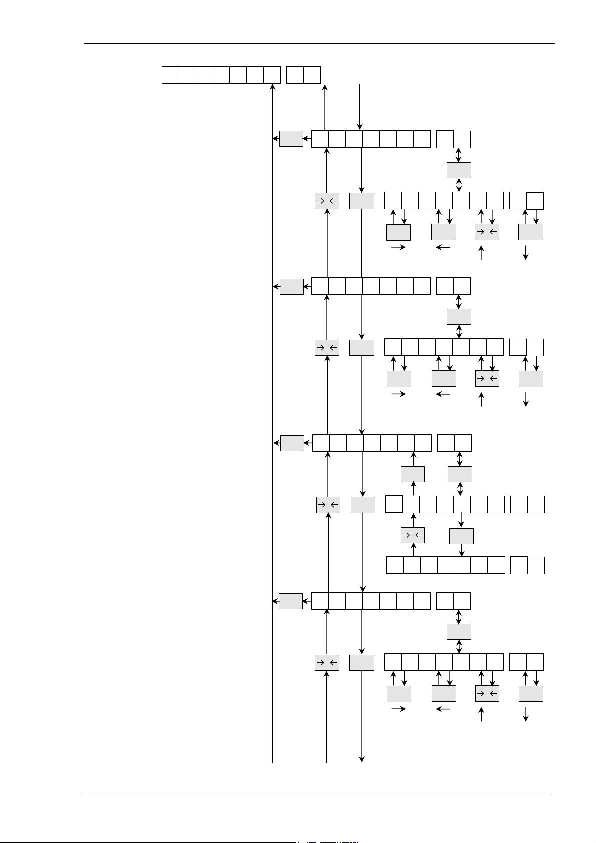
1.1.4. Keypad
Display in weighing mode Display in setup mode
FUNC
Entry in setting modes according
followed key inputs
(see page 67)
Shifting active cursor position one
position to the left
SHIFT
Entry into code display modes
according followed key inputs
Shifting active cursor position one
position to the right
if pressed the weighing value is
0
zeroed, the Gross weight becomes
Zero. Only available when “ZALM”
is inactive.
Æ one step up in navigation at the
present level
Æ incrementing the value of active
(flashing) character position
Æ toggle between on / off display
GROSS
/NET
if pressed the weighing value display
toggled between Gross and Net
indicated by the
or sign
Æ one step down in navigation at the
present level
Æ decrementing the value of active
(flashing) character position
Æ toggle between on / off display
if pressed the Tare weight will be
subtract, Net weight becomes Zero
TAR E
(ESC)
and “TARE” -sign switches on;
SHIFT
to clear Tare weight press
6
LOWER
then
Signs
Press
.
are illuminated.
TAR E
for 2 sec and tare weight
and
Æ if pressed in setup mode the
present action is terminated and the
setting goes one level up;
Æ in first setting level this key
terminates the setup mode and
returns the display to weighing mode
is cleared.
ENT
Default: Print;
User defined action selectable.
(Refer to 3.1.15.1)
Confirms the present setting.
Changed Parameter will be stored.
1
UPPER
…..
direct display and setting of values of
the presently selected code
9
CPS
A.S.T. Angewandte SYSTEM-TECHNIK GmbH Dresden Page 9
Page 12

Manual of Weighing Controller A 810
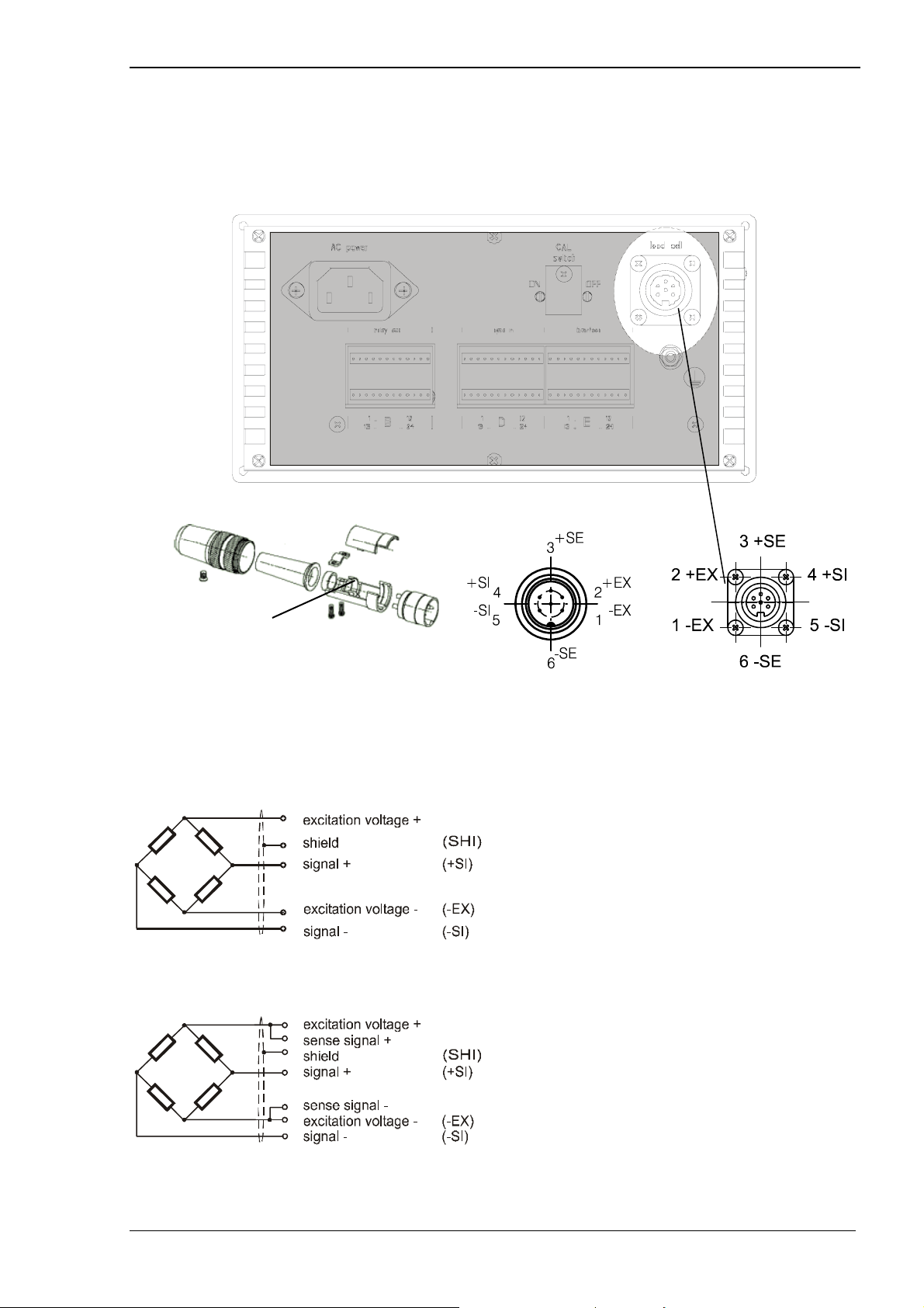
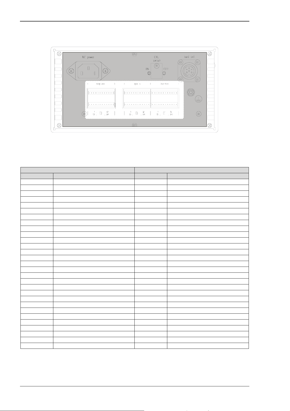
1.1.5. Rear Panel
AC Power Input Connector
1
AC input is labeled with the standard AC voltage of the country in
which the unit was purchased.
Available voltage is: 115 or 230 V AC
Confirm the correct voltage on your A810. AC frequency is 48 to 62 Hz
and voltage supply -15 to +10%
2
Output Connector
Interface Connector for RS232, TTY, RS485
3
Load cell connector Refer to Page 11 – Loadcell Connector
4
Calibration lock
5
Control signal Input/ Refer to Page 12 - PIN- Assignment of Control Signal Input / Output
Connector
1.2. Panel cut size
Page 10 A.S.T. Angewandte SYSTEM-TECHNIK GmbH Dresden
Page 13
Manual of Weighing Controller A 810
2. Connections
2.1. Loadcell Connector
Shield
4 wire standard:
Frontview
(+EX)
6 WIRE FOR REMOTE SENSING:
(+EX)
(+SE)
(-SE)
A.S.T. Angewandte SYSTEM-TECHNIK GmbH Dresden Page 11
Page 14
Manual of Weighing Controller A 810
2.2. PIN- Assignment of Control Signal Input / Output Connector
Connector A: Power
B: Control- Output- Signals
D: Control- Input- Signals
E: RS232, RS485, TTY- Interface, 4...20mA norm output
Connector B / Output-Signals Connector D / Input-Signals
PIN Signal PIN Signal
B13 COM *2 D3 COM *2
B1 SP1 D4 G/N
B2 SP2 D5 D/Z ON
B3 SP3/ CPS D6 Tare subtraction ON
B4 near zero D7 Tare subtraction OFF
B14 COM *2 D12 COM *2
B5 under D8 Hold or Judgment
B6 over D9 Feed/ Discharge
B7 lower limit D10 start *1
B8 upper limit D11 stop *1
B15 COM *2 D24 COM *2
B9 stable D16 start accumulation
B10 discharge D17 clear accumulation sum
B11 go D18 user defined function
B12 complete D19 user defined function
B16 COM *2 D15 COM *2
B21 sequence active *1 D20 Code No. 8
B22 run D21 Code No. 4
B23 sequence error D22 Code No. 2
B24 weight error D23 Code No. 1
B17 GND, extern I/O D1
B18 GND, extern I/O D2
B19 +24V, extern I/O D13
B20 +24V, extern I/O D14
*1 are effective in sequence mode
*2 COM- terminals are not connected internally
Page 12 A.S.T. Angewandte SYSTEM-TECHNIK GmbH Dresden
Page 15

Manual of Weighing Controller A 810
Connector E Description Remarks
E1 RxD5+ TTY (Port 4)
E2 RxD5- TTY (Port 4)
E3 TxD5+ TTY (Port 4)
E4 TxD5- TTY (Port 4)
E5 GND RS232
E6 GND RS232
E7 TxD2 RS232 (Port 1)
E8 RxD2 RS232 (Port 1)
E9 R(A) RS485 (Port0)
E10 R(B) RS485 (Port0)
E11 D(Z) RS485 (Port0)
E12 D(Y) RS485 (Port0)
E13 GND_24
E14 P24
E15 U-OUT DAC (0…10V)
E16 I-OUT DAC (0…20mA)
E17 GND_24 DAC
E18 AUTO_SENSOR
E19 RxD3 RS232 (Port 2)
E20 TxD3 RS232 (Port 2)
E21 R(A) RS485 (Port0)
E22 R(B) - Rt RS485 (Port0)
E23 D(Z) RS485 (Port0)
E24 D(Y) - Rt RS485 (Port0)
Please refer to section 4.6 “Examples of Communication Interfaces” at page 87 for a detailed description
of interfaces.
external ground
optocoupler
external sypply
optocoupler
A.S.T. Angewandte SYSTEM-TECHNIK GmbH Dresden Page 13
Page 16
Manual of Weighing Controller A 810
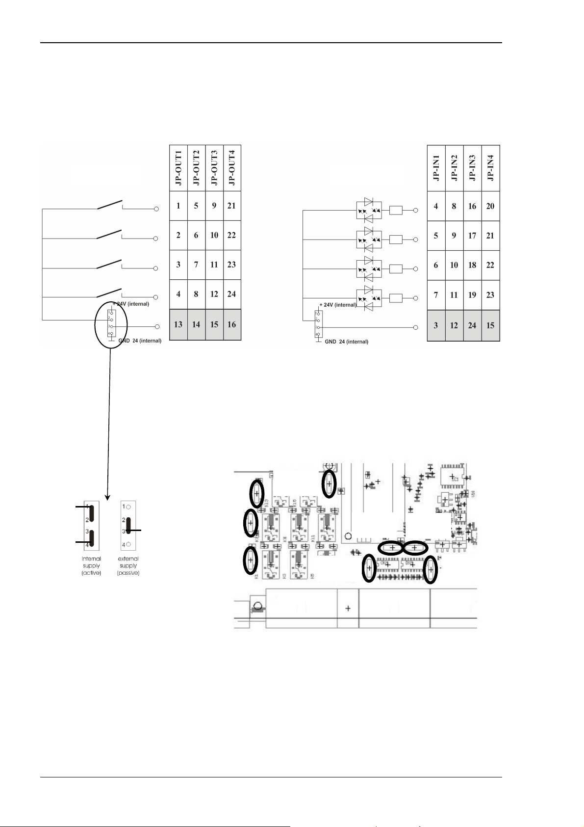
Relay outputs (connector B) and Opto inputs (connector D) can either be with power (active) or neutral
(passiv) depending on interal jumper position on mainboard. Both Input and Output connectors are
separated into four groups. Each group contains four signals with dedicated COM. By setting each
individual jumper’s position to decide each group whether the I/O are with power or neutral.
Connector B Connector D
COM COM
Fig. 1 Internal schematic of Relay Output (B) and Opto Input (D)
I/Os are I/Os are
with power neutral
+24V
COM
JP- OUT3
(B9-12)
JP- OUT2
(B5-8)
JP-OUT4
(B21-24)
Gnd
JP-OUT1
(B1-4)
JP-IN4
(D20-23)
Fig. 2 Jumper setting
JP-IN1
(D4-7)
JP-IN2
(D8-11)
JP-IN3
(D16-19)
B D E
Fig. 3 Jumper positions on mainboard
Page 14 A.S.T. Angewandte SYSTEM-TECHNIK GmbH Dresden
Page 17
Manual of Weighing Controller A 810
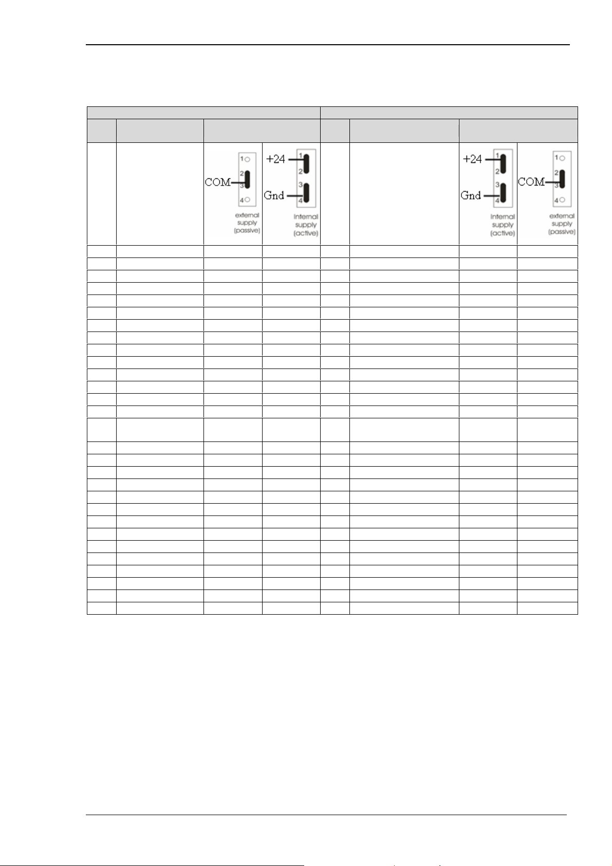
Jumper-Positions:
Connector B / Output-Signals Connector D / Input-Signals
PIN Signal Polarity (JP-OUT1…4) PIN Signal Polarity (JP-IN1…4)
B13 COM none *2 - D3 COM - none *2
B1 SP1 none + D4 G/N + none
B2 SP2 none + D5 D/Z ON + none
B3 SP3/ CPS none + D6 Tare subtraction ON + none
B4 near zero none + D7 Tare subtraction OFF + none
B14 COM none *2 - D12 COM - none *2
B5 under none + D8 Hold or Judgment + none
B6 over none + D9 Feed/ Discharge + none
B7 lower limit none + D10 start *1 + none
B8 upper limit none + D11 stop *1 + none
B15 COM none *2 - D24 COM - none *2
B9 stable none + D16 start accumulation + none
B10 discharge none + D17
B11 go none + D18 user defined function + none
B12 complete none + D19 user defined function + none
B16 COM none *2 - D15 COM - none *2
B21 Sequence active None *1 + D20 Code No. 8 + none
B22 run none + D21 Code No. 4 + none
B23 sequence error none + D22 Code No. 2 + none
B24 weight error none + D23 Code No. 1 + none
B17 GND, extern I/O - - D1 not used none none
B18 GND, extern I/O - - D2 not used none none
B19 +24V, extern I/O + + D13 not used none none
B20 +24V, extern I/O + + D14 not used none none
default default
*1 are effective in sequence mode
*2 COM- terminals are not connected internally
clear accumulation
sum
+ none
A.S.T. Angewandte SYSTEM-TECHNIK GmbH Dresden Page 15
Page 18
Manual of Weighing Controller A 810
2.3. Control Input Signals
- Gross / Net (G/N) (pin D4)
(edge triggered)
Display value is switched between Gross and Net by pressing key or by changing input
D4.
When input signal is shorted to COM (OFFÆON) Net weight is displayed.
When input signal is opened to COM (ONÆOFF) Gross weight is displayed.
Pressing dedicated key will always toggle between Net and Gross, independent of input signal.
- Digital Zero (DZ) (pin D5)
(edge triggered)
The Gross weight is set to zero by pressing key or by shorten input D5 to COM
(OFFÆON).
When “ZALM” is illuminated, Digital Zero Regulation Value is exceeded and no setting to zero can
be done. Refer to 3.1.1.3 and 3.1.1.4 at page 25 for zero settings.
- Tare substraction (TARE) (pin D6)
(edge triggered)
The Net weight is set to zero by pressing key or by shorten input D6 to COM (OFFÆON).
Taring depends on its mode (3.1.1.10 at page 26) and its limit (3.1.1.9 at page 26).
- Tare Reset (TARE long press, when is illuminated )
(pin D7)
(edge triggered)
The Net weight is brought to Gross weight by pressing key and then key.
6
LOWER
After that is illuminated. Reset Taring weight by pressing for longer then 1s or by
shorten input D7 to COM (OFFÆON).
- Hold or Judgement (pin D8)
(level triggered)
The weighing value is hold by shorten input D8 to COM (OFFÆON) and “HOLD” is illuminated.
Over/Go/Under (3.1.7.4 at page 42) and Upper/Lower (3.1.7.5 at page 42) Limit have to be both
set to “0”.
At other settings the input switches to “Judgement”.
Over/Go/Under comparison mode (“OUC-MD”, 3.1.7.4 at page 42):
0: compare always
1: compare when judging input is ON
2: compare when complete output is ON
3: compare when complete output is ON
and weight will be hold during that time
Note: “Hold mode” is only available in Simple Comparison mode.
Page 16 A.S.T. Angewandte SYSTEM-TECHNIK GmbH Dresden
Page 19

Manual of Weighing Controller A 810
- Feed/ Discharge (pin D9)
(level triggered)
Feed or Discharge is accessed by shorten(Discharge) or open (Feed) input D9 to COM.
“Fd-Con” (3.1.6.2 in submenu “control” at page 39 has to be “2”).
0: feeding
1: discharge
2: external control
During Dischrage mode, “Upper/ Lower Limits” has to be compared with Gross weight (“ULLCMD” 3.1.7.3 set to “0”) and “Final/Over/Under” has to be ompared with Net weight (“FOU-CMD”
3.1.7.2 set to “1”).
Note: “Discharge mode” is only available in Simple Comparison mode.
- Start (pin D10)
(edge triggered)
During “Sequence mode” shorten input D10 to COM will start sequence cycle.
- Stop (pin D11)
(edge triggered, level triggered)
During “Sequence mode” shorten input D11 to COM will stop sequence cycle or clears sequence
errors.
Refer to 6.6 “Sequence mode” at page 103 for more detail.
- Start accumulation (pin D16)
(edge triggered)
Accumulation is done when shorten input D16 to COM (OFFÆON) and at rising edge of
“Complete output” signal. FOUC-MD (3.1.7.2 at page 41) has to be set to 0 (gross) or 1 (net).
“Func” + “3”: shows sum of accumulated weight
“Func” + “4”: shows counter of accumulated weight cycles
- Clear accumulation (pin D17)
(edge triggered)
Accumulation Counter and weight value is cleared when shorten input D17 to COM (OFFÆON)
for more than 3 seconds. For confirmation “del Acc” will be displayed.
- User Function I (pin D18)
(edge triggered)
This user defined function is activated when shorten input D18 to COM (OFFÆON).
Refer to 3.1.16.1 at page 64.
A.S.T. Angewandte SYSTEM-TECHNIK GmbH Dresden Page 17
Page 20

Manual of Weighing Controller A 810
- User Function II (pin D19)
(edge triggered)
This user defined function is activated when shorten input D19 to COM (OFFÆON).
Refer to 3.1.16.2 at page 64.
- Code selection (pins D20-23)
(level triggered)
This binary input select active codeset when inputs are shortened to COM. “External Code”
(3.2.3.2 at page 67) has to be “ON”.
Any selected codeset greater than 9 will generate “Err110”.
D23 is low-bit and D20 is high-bit.
Example: binary presentation
Selection of codeset 5: shorten D23 to COM (code N°1); 1
open D22 to COM (code N°2); 0
shorten D21 to COM (code N°4); 1
open D20 to COM (code N°8); 0
Page 18 A.S.T. Angewandte SYSTEM-TECHNIK GmbH Dresden
Page 21

Manual of Weighing Controller A 810
2.4. Control Output Signals
- Setpoint1 (SP1) (Pin B1)
(low-activ)
Will set „ON“, if setpoint1 SP1 (3.2.3.2.7, p.69) of active codeset has been exceeded.
- Setpoint 2 (SP2) (Pin B2)
(low-activ)
Will set „ON“, when setpoint2 SP2 (3.2.3.2.5, p.68) of active codeset has been exceeded.
- Setpoint3/ Compensationpoint (SP3/CPS) (Pin B3)
(low-activ)
Will set „ON“, when setpoint3 SP3/CPS (3.2.3.2.3, p.68) of active codeset has been exceeded.
- Near Zero (NZ) (Pin B4)
(low-activ )
Will set „ON“, when actual weight has gone below Near Zero value (3.2.3.2.13, p.71) of active
codeset.
- Under (LO>) (Pin B5)
(Low-aktiv)
Will set „ON“, when actual weight has gone below Final-UNDER value (3.2.3.2.10, p.70) of active
codeset.
- Over (<HI) (Pin B6)
(low-activ)
Will set „ON“, when actual weight has exceeded Final+OVER value (3.2.3.2.9, p.70) of active
codeset.
- Lower Limit (LO LIM) (Pin B7)
(low-activ)
Will set „ON“, when actual weight has gone below Lower Limit value (3.2.3.2.12, p.70) of active
codeset.
- Upper Limit (HI LIM) (Pin B8)
(low-activ)
Will set „ON“, when actual weight has exceeded Upper Limit value (3.2.3.2.11, p.70) of active
codeset.
A.S.T. Angewandte SYSTEM-TECHNIK GmbH Dresden Page 19
Page 22

Manual of Weighing Controller A 810
- Stable (STAB) (Pin B9)
(low-activ)
Will set „ON“, when actual weight matches stable conditions.
Parameter that affect that condition are:
Stable number “StAN”, 3.1.1.11, p.27;
Stable range “StAR”, 3.1.1.12, p.27;
ADC sampling rate “SR”, 3.1.3.3, p.32;
Filter component “FC”, 3.1.3.1, p.32;
Threshold of filter jump “FT”, 3.1.3.2, p.32;
- Discharge (Pin B10)
(low-activ)
Will set „ON“, when “Complete”-signal is set in sequence-mode. Duration of that signal is set via
Discharging time “dIS-TI” (p.46).
- Go (GO) (Pin B11)
(low-activ)
Will set „ON“, when actual weight is between threshold underweight UN (3.2.3.2.10, p.70) and
overweight OV (3.2.3.2.9, p.70) of active codeset.
- Complete (Pin B12)
(low-activ)
Will set „ON“, when conditions under Complete signal output mode “CSO-MD” (3.1.6.3, p.39) are
fulfilled. Duration of that signal is set via Complete output time “COTI” (p.43).
- Sequence active (Pin B21)
(low-active)
Will set “ON”, when “Start”-signal is activated. Will set “OFF”, when “Complete”-signal is finished
or an error is reset.
- Run (Pin B22)
(low-activ)
Will set „ON“, when A810 is ready for operation.
- Sequence error (Pin B23)
(low-activ)
Will set „ON“, when an error during a weighing cycle has occurred. Observation via Near zero
confirmation “NZC” (p.45) and Setpoint SP1 confirmation “SPC” (p.46) possible.
- Weight error (Pin B24)
(low-activ)
Will set „ON“, when an error of A810 or load cell has occured. Refer to „Description of States of
Error“ at page 112.
Page 20 A.S.T. Angewandte SYSTEM-TECHNIK GmbH Dresden
Page 23

Manual of Weighing Controller A 810
3. How to get started
At delivery the A810 is preset on default parameters (comply with legal-for-trade) to operate as a simple
scale provided the resolution is set and the calibration has been carried out.
The following section explains how to setup the instrument according the required function by using the
front panel keypad and display.
As an option a sophisticated Windows® based setup program is available to make the adjustment easier
and faster. Via PC-Programm all parameter can be saved for backup in a separate file, the print image is
changable and A810 can send weighing- and status-strings to PC via commands (see separate
information).
A.S.T. Angewandte SYSTEM-TECHNIK GmbH Dresden Page 21
Page 24
Manual of Weighing Controller A 810
p
p
p
p
p
p
p
p
p
p
p
p
p
p
p
p
p
p
p
p
p
p
p
p
p
p
p
p
p
p
p
p
p
p
p
p
p
p
p
p
p
p
p
p
p
p
p
p
p
p
p
p
p
p
p
p
p
p
p
p
p
p
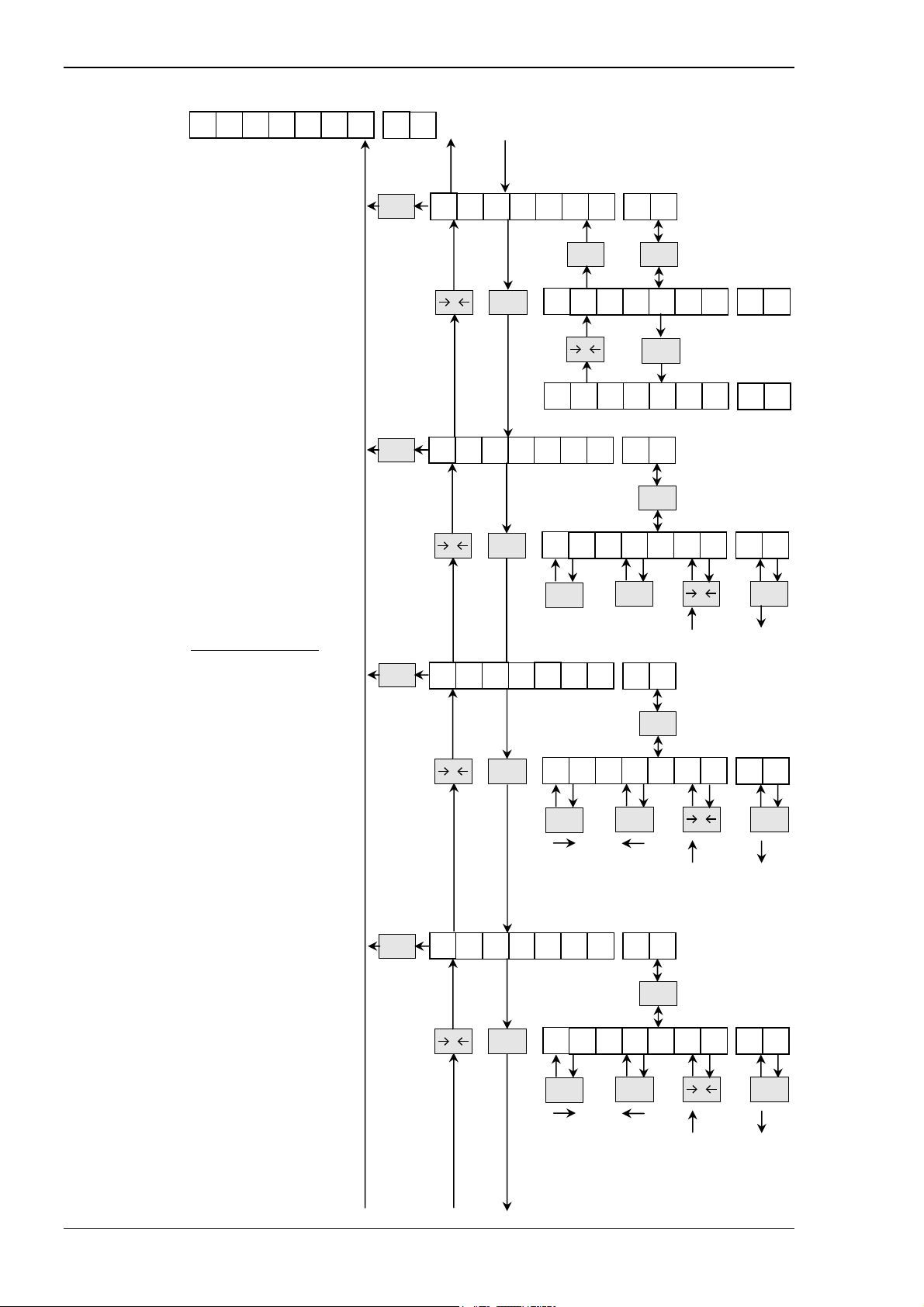
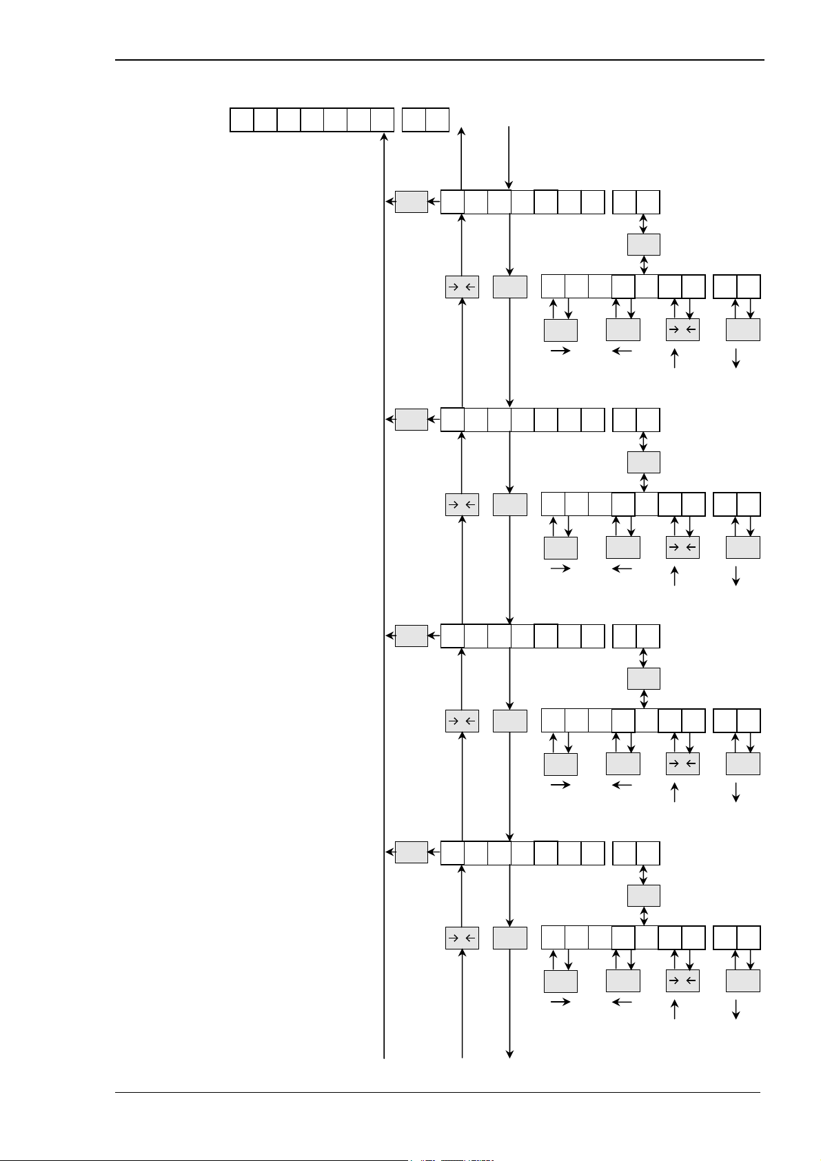
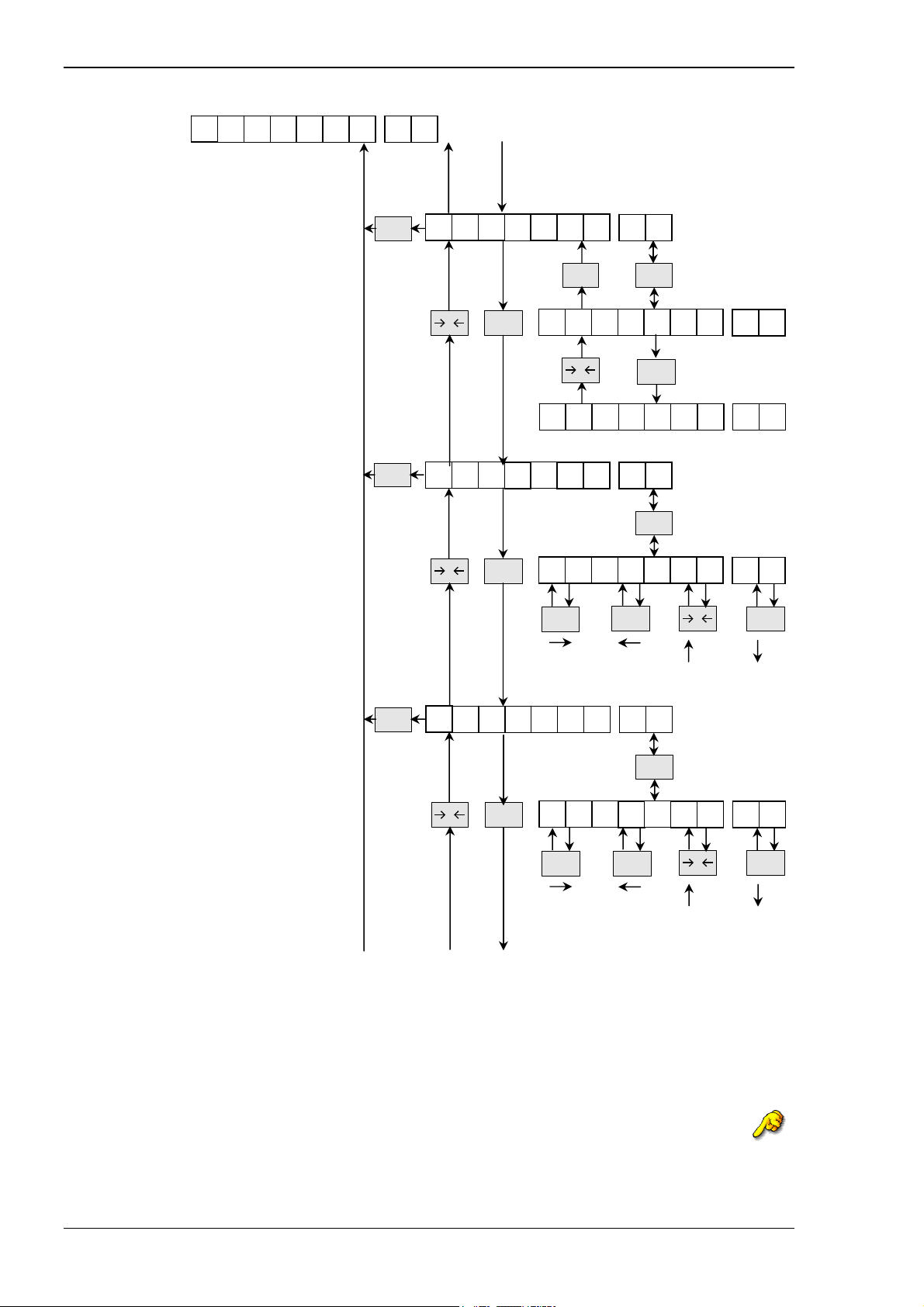
3.1. Parameter setup section
To enter into the parameter setup please press
SHIFT
9
CPS
. 24
. 30
. 32
. 24
. 24
. 25
. 25
. 25
. 25
. 30
. 30
. 30
. 32
. 32
. 33
. 33
. 34
. 35
. 35
. 36
. 36
. 34
. 36
. 34
. 37
. 37
. 26
. 37
. 26
. 38
. 26
. 26
. 27
. 27
. 27
. 28
. 28
. 28
. 29
. 29
. 52
. 52
. 52
. 52
. 52
. 53
. 54
. 54
. 54
. 54
. 55
. 55
S. 57
S. 57
S. 58
. 60
. 60
. 60
. 60
. 61
. 55
. 61
. 55
. 61
. 61
Page 22 A.S.T. Angewandte SYSTEM-TECHNIK GmbH Dresden
Page 25
Manual of Weighing Controller A 810
p
p
p
p
p
p
p
p
p
p
p
p
p
p
3
p
p
p
5
p
p
5
p
p
p
6
p
p
p
p
p
p
p
p
p
p
p
p
p
p
p
p
p
p
p
p
p
p
p
p
p
p
p
p
p
p
p
p
p
p
p
. 62
. 62
. 62
. 62
. 62
. 39
. 39
. 39
. 39
. 40
. 40
. 40
. 40
. 41
. 42
. 42
. 42
. 42
. 43
. 4
. 64
. 64
. 64
. 64
. 64
. 66
. 66
. 66
. 66
. 66
. 66
. 46
. 44
. 44
. 4
. 45
. 4
. 46
. 4
. 47
. 48
. 48
. 48
. 48
. 48
. 49
. 49
. 49
. 50
. 50
. 50
. 50
. 50
. 51
. 51
. 51
. 51
A.S.T. Angewandte SYSTEM-TECHNIK GmbH Dresden Page 23
Page 26
Manual of Weighing Controller A 810
3.1.1. Submenu “Basic”
This menu contains the basic adjustments affecting the ability of the scale to be approved for calibration.
The adjustment might be carried out before calibration.
3.1.1.1. Enable Setup “Set”
Alternative decision to enable access
to a reduced setup section via function
call 108.
When ON, only parameters that not affect
legal-for-trade settings are available.
When OFF function call has no affect.
default setting: off
Refer to 5.3 at page 93 for locked menus.
TAR E
GROSS
0
/NET
b A S
ENT
S
TAR E
o
F F
0
o
n
I
E
C
T
ENT
GROSS
/NET
S
E
T
S
E
T
3.1.1.2. Select primary
measurement unit
TAR E
M
U
“MU”
Select one of the units
KG, To, Gr, Lb, oz, N, KN and FU (free unit)
as primary unit.
This unit is used for scale settings and
calibration.
default setting: KG
The Weighing Controller A810 will be calibrated with this unit and after each restart this unit is shown.
Note: Free Unit “FU” is scaled and calibrated as “KG”. Setting appropriate chars for “FU” is done in
“basic” menu 3.1.1.16 and 3.1.1.17 at page 28.
GROSS
0
/NET
TAR E
ENT
0
scroll between active
units
K
GROSS
G
/NET
Page 24 A.S.T. Angewandte SYSTEM-TECHNIK GmbH Dresden
Page 27
Manual of Weighing Controller A 810
3.1.1.3. Range of zero setting
lower limit “LLZS”
The lower limit of zero setting range
can be adjusted between 0 … –20%
of full scale.
default setting: 1
3.1.1.4. Range of zero setting
b
A S
TAR E
TAR E
I
C
0
GROSS
/NET
L L
>
SHIFT
cursor
right
U L
Z
FUNC
cursor
left
Z
S
ENT
S
+1
incr. decr.
0
value
0
GROSS
/NET
1
-1
upper limit “ULZS”
FUNC
cursor
left
Z
Z
ENT
T
ENT
GROSS
/NET
T
+1
incr. decr.
0
value
0
GROSS
/NET
Z
Z
3
-1
T
T
The upper limit of zero setting range
is adjustable between 0 … 20% of FS
and indicates in which range the zero
setting function is operating.
default setting: 3
3.1.1.5. Zero tracking “ZT”
This toggle decision enables or disables
the zero tracking option.
default setting: off
3.1.1.6. Zero tracking
TAR E
TAR E
GROSS
0
/NET
cursor
GROSS
0
/NET
>
SHIFT
right
TAR E
o
F F
0
o n
d
distance “dZT”
FUNC
cursor
left
ENT
0
0
value
GROSS
/NET
0
+1
incr. decr.
5
-1
Set in terms of number of divisions
(tenth of division per second) in the
range of 0…100.
Weight deviations within the
selected window that have been stable
for more than one second is tracked off.
Please note: zero tracking should be off
for most set point filling operations to
prevent tracking off any product trickle at
the start of the filling process.
default setting: 5 (0.5 divisions per second)
A.S.T. Angewandte SYSTEM-TECHNIK GmbH Dresden Page 25
GROSS
0
/NET
>
SHIFT
cursor
right
Page 28
Manual of Weighing Controller A 810
b
A S
3.1.1.7. Power-on zero
setting “POZS”
This toggle decision enables or
disables the power-on zero setting
option. Range is selected at 3.1.1.3
(Lower Limit) and 3.1.1.4 (Upper Limit)
previous page.
default setting: off
3.1.1.8. Minimum Load “ML”
Set in terms of divisions in the range of
0 … 250.
This value indicates the trigger for the
print out.
default setting: 20
Æ If enabled and other settings are default
printing is possible when weight >2kg
is on load cell (20(ML)*300kg(FS)
3000(DN)
=2kg)
3.1.1.9. Upper limit taring
range “ULtAR”
Set in terms of percentage of full scale
in the range of 0 … 100%.
It indicates the weight above zero up to
which an enabled tare option is operating.
default setting: 100
3.1.1.10. Taring Mode “tAR_M”
This mode selection defines the action
after the tare command.
Set in terms of numbers in the range from
0, 1 or 2.
mode 0 tare always;
mode 1 tare only when stable;
mode 2 if stable Æ tare
not stable Æ tare if stable
is reached
default setting: 2
I
TAR E
TAR E
TAR E
TAR E
C
0
0
0
0
GROSS
/NET
GROSS
/NET
GROSS
/NET
GROSS
/NET
U
t A R
o
o
>
SHIFT
L t
>
SHIFT
cursor
right
>
SHIFT
cursor
right
P O
TAR E
F F
0
n
Z
M
FUNC
A R
FUNC
cursor
left
FUNC
cursor
left
S
ENT
GROSS
/NET
L
ENT
ENT
M
ENT
P O
P O
incr. decr.
incr. decr.
0 2
0
+1
value
1
0
+1
value
Z S
Z
0
0
+1
value
incr. decr.
0
GROSS
/NET
-1
0
GROSS
/NET
-1
2
GROSS
/NET
-1
S
Page 26 A.S.T. Angewandte SYSTEM-TECHNIK GmbH Dresden
Page 29
Manual of Weighing Controller A 810
3.1.1.11. Stable number “StAN”
Set in terms of numbers in the range
between values from 10 … 250.
This value defines the number of
averaged ADC values taken into account
for testing the stable condition.
A higher number provides a safer stable
condition but it also extends the minimum
time necessary to recognize the stable
condition after a load has been changed.
default setting: 50
3.1.1.12. Stable range “StAR”
Set in terms of tenth of a division in the
range of 1 to 255.
This value defines the range of tolerance
a weighing sample has match in order to
meet the stable condition.
A higher value provides a safer and
faster stable condition.
default setting: 10
3.1.1.13. Limit underload “LUNL”
Set in terms of divisions in the range of
0 to 1000.
This value defines the number of divisions
below zero that have to be indicated
before the underload message has been
generated.
default setting: 9
3.1.1.14. Limit overload “LOVL”
Set in terms of divisions in the range of
0 to 1000.
This value defines the number of divisions
above FS (max.) that have to be indicated
before the overload message has been
generated.
default setting: 9
A.S.T. Angewandte SYSTEM-TECHNIK GmbH Dresden Page 27
b
A S
I
TAR E
TAR E
TAR E
TAR E
C
0
0
0
0
GROSS
/NET
GROSS
/NET
GROSS
/NET
GROSS
/NET
S t
>
SHIFT
cursor
right
S t
>
SHIFT
cursor
right
L U
>
SHIFT
cursor
right
L O
>
SHIFT
cursor
right
A
FUNC
cursor
left
A
FUNC
cursor
left
N
FUNC
cursor
left
V
FUNC
cursor
left
ENT
ENT
ENT
ENT
N
R
L
0
L
0
0 0
0 0
0
5
value
0
value
GROSS
1
GROSS
0
+1
incr. decr.
0
+1
incr. decr.
0
0
+1
incr. decr.
GROSS
value
0
0
+1
incr. decr.
GROSS
value
0
/NET
-1
0
/NET
-1
9
/NET
-1
9
/NET
-1
Page 30
Manual Weighing Controller A 810
3.1.1.15. Enable quickstart
b A S
I
TAR E
C
E n
“EnQS”
This toggled decision defines whether the
Power-on self test of the display is a full
version (OFF) or just limited to a short
segment test (ON).
default setting: off
3.1.1.16. Select character of
TAR E
GROSS
0
/NET
TAR E
o
o n
free unit “CM1”
Sets the character at left of the unit.
Refer to appendix 7.1 ASCII-table
at page 108.
default setting: 32 (means “space”)
3.1.1.17. Select character of
TAR E
GROSS
0
/NET
>
SHIFT
cursor
right
free unit “CM2”
Sets the character at right of the unit.
Refer to appendix 7.1 ASCII-table
at page 108.
default setting: 32 (means “space”)
Example:
Desired measurement unit is “kp”.
- enable free unit “FU” by setting it “ON” (3.1.1.2) then
- left character is “k” Æ in submenu “CU1” select “107” and press key “ENT” then
- right character is “p” Æ in submenu “CU2” select “112” and press key “ENT”
Refer to 7.1 ASCII-Table at page 108 for assigning numbers to characters.
GROSS
0
/NET
>
SHIFT
cursor
right
Q
S
ENT
F F
0
C
C
cursor
GROSS
M 1
ENT
FUNC
left
M
/NET
2
ENT
FUNC
cursor
left
E n
E n
+1
incr. decr.
+1
incr. decr.
0
0
0
value
0
value
Q
Q
3 2
3
S
S
GROSS
/NET
-1
2
GROSS
/NET
-1
Page 28 A.S.T. Angewandte SYSTEM-TECHNIK GmbH Dresden
Page 31

Manual of Weighing Controller A 810
3.1.1.18. Set to default “dEF”
Toggled decision to set all parameters
of the “BASIC” sub menu to the default
values when ON.
default setting: off
3.1.1.19. Clear Setup “CLEAR”
Toggled decision to set all parameters
of the whole Setup menu to the default
values when ON.
default setting: off
Note: When clearing Setup-Parameter even calibration is lost. For backup reasons use Windows® Program before clearing.
b
A S
TAR E
TAR E
I
C
GROSS
0
/NET
C L E
d
TAR E
o
F F
0
o
n d
TAR E
o
F F C L E
0
o
n
E F
ENT
GROSS
/NET
A
R
ENT
GROSS
/NET
C
d
L E
E F
E
F
A
R
A R
A.S.T. Angewandte SYSTEM-TECHNIK GmbH Dresden Page 29
Page 32

Manual Weighing Controller A 810
3.1.2. Submenu “Scale division”
This menu is used to setup parameters for the selected unit “MU” 3.1.1.2 at page 24. Each used unit
needs to be defined, the full scale interval (Dn) and the verification scale interval (VS).
See 6.1”Calibration procedure” at page 94 for more detail.
3.1.2.1. Parameter for unit “MU”
TAR E
TAR E
TAR E
d
0
I
GROSS
0
/NET
GROSS
/NET
V
ENT
preset values:
100, 200, 300,
500, 600, 800,
1000, 1200,
1500, 1600,
2000, 2400,
2500, 3000,
4000, 5000,
6000, 8000,
10000, 12000,
15000, 20000,
25000, 30000
0
+1
TAR E
0
+1
TAR E
TAR E
3 0 0 0
GROSS
/NET
-1
when Dn = 0
>
SHIFT
cursor
right
ENT
GROSS
/NET
ENT
3
D
N
ENT
0 0 3 0
FUNC
cursor
left
V
S
preset values:
1; 2; 3; 4; 5
times multiple of 10
-1
F
S
0
0. 1
D
0
ENT
0
value
incr. decr.
0. 1
k
S
C A L E
3.1.2.1.1. Divisions “DN”
Confirming this menu by pressing
ENT
the operator reach the
section of preset values like 100,
200, 300, 500, … 30000.
If the preset value 0 is selected by
pressing an input box will
ENT
be opend to enter a free FS-value
in range between 100 … 100000.
Pressing continues the input
ENT
and returns one level up.
default setting: 3000
3.1.2.1.2. Verification scale
interval “VS”
Confirming this menu by pressing
the operator reaches the
ENT
section of preset division size
values like 0,0001 … 100.
This division size indicates the
count-by value and decimal point.
default setting: 0,1
Note: 1VS = 1e (OIML)
3.1.2.1.3. Fullscale “FS”
This option is used for checking the
value for full scale (FS) and the value
for verification scale interval (VS) have
been entered correctly. The display will
read out fullscale + 1 VS.
In case of default settings the display will
show “300,1kg”
N
0 0
GROSS
/NET
G
-
Page 30 A.S.T. Angewandte SYSTEM-TECHNIK GmbH Dresden
Page 33

Manual of Weighing Controller A 810
Examples:
I.)
Desired: Fullscale 100kg
Resolution 0.01kg
Menu
- Stability settings are done according to operators environment.
- set “MU” to “kg” 3.1.1.2
- “Dn” = 100kg / 0.01kg = 10000
set “Dn” to 10000 Æ A810 is legal-for-trade 3.1.2.1.1
- set “VS” = 0.01 3.1.2.1.2
- for confirmation of correctly set parameters: “FS” shows 100.01kg 3.1.2.1.3
II.)
Desired: Fullscale 30t
Resolution 0.002t
Menu
- Stability settings are done according to operators environment.
- set “MU” to “t” 3.1.1.2
- “Dn” = 30t / 0.002t = 15000
set “Dn” to 15000 Æ A810 is not legal-for-trade 3.1.2.1.1
- set “VS” = 0.002 3.1.2.1.2
- for confirmation of correctly set parameters: “FS” shows 30.002t 3.1.2.1.3
A.S.T. Angewandte SYSTEM-TECHNIK GmbH Dresden Page 31
Page 34

Manual Weighing Controller A 810
3.1.3. Submenu “ADC”
This menu is used to select the ADC and filter characteristics of the data acquisition. Analogue
parameters like gain and offset are preset during the production test procedure and need no further
adjustment.
3.1.3.1. Filter component “FC”
Set in terms of number between 10 to
250 this value defines the number of
samples from the ADC to be used for
the continuously moving averaging filter
in connection with the ADC sampling
rate. Lower value provides faster stable.
default setting: 50
3.1.3.2. Threshold of filter
jump “FT”
Set in an range between 50 to 1000000
This value represents the ADC integer
value when the sliding filter is stopped
and restarted to trace any load change
directly.
This value should be slide above the
Maximum of interference caused by
vibrations. Higher value provides faster
stable.
default setting: 500
3.1.3.3. ADC sampling rate “SR”
Set in terms of preset values for standard
sampling rate and corresponds to the
number of samples per second
achieved by the ADC.
In connection to the filter settings the
system can be adjusted to the
application. Higher value is faster.
default setting: 50 samples / sec
Note: When SR = 100, “StAN” (3.1.1.11) is set automatically to 100 when “StAN” is greater than 100.
When SR = 200, “StAN” (3.1.1.11) is set automatically to 10 when “StAN” is greater than 10.
When SR = 400, “StAN” (3.1.1.11) is set automatically to 2 when “StAN” is greater than 2.
TAR E
TAR E
TAR E
0
0
0
GROSS
/NET
GROSS
/NET
GROSS
/NET
A
D
ENT
>
SHIFT
cursor
right
>
SHIFT
cursor
right
TAR E
5 0
C
F C
FUNC
cursor
left
F T
FUNC
cursor
left
S
ENT
ENT
R
ENT
incr. decr.
incr. decr.
Sampling rates
25; 50; 100;
200; 400
samples/sec
0
+1
0
+1
0
+1
value
5
value
5
0
S
GROSS
GROSS
/NET
GROSS
/NET
/NET
-1
-1
0
0
-1
R
Page 32 A.S.T. Angewandte SYSTEM-TECHNIK GmbH Dresden
Page 35

Manual of Weighing Controller A 810
3.1.3.4. Display Frequency
This option regulates refreshing rate
of display. Value * 10ms = frequency.
Lower value means faster diplay
frequency.
default setting: 030 (3Hz)
3.1.3.5. Set to default “def”
This is an option to reset all parameter
of the “ADC” sub menu to default values
when ON.
Warning: Calibration is lost!
A
D
C
TAR E
TAR E
d I S P
GROSS
0
/NET
d
-
R
TAR E
TAR E
o
F F d
0
o
n
ENT
E
F
ENT
GROSS
/NET
Display frequency
0.4…32
samples/sec
0
3
0
ENT
E
GROSS
/NET
-1
F
F
0
+1
d E
A.S.T. Angewandte SYSTEM-TECHNIK GmbH Dresden Page 33
Page 36

Manual Weighing Controller A 810
3.1.4. Submenu “Calibration”
This menu allows the operator to perform either a practical or a theoretical calibration. During the practical
calibration a desired load has to be applied a zero / full scale span calibration by using of at least two
points. Additional entered points will increase the accuracy.
The theoretical calibration allows to enter the known input voltage ratios but it will not reach the accuracy
of a practical calibration due to tolerances of electronic components.
TAR E
C
A L I B
ENT
3.1.4.1. Two position practical
calibration “2P”
The two position calibration allows the
zero of the scale and some other value at
almost any position of its characteristics,
assumed that the complete system is
linear.
3.1.4.1.1. Zero calibration “ZC”
This zero calibration is always the first
step to determine the calibration data.
After pressing the information
come up to remove any load. An
additional pressing
starts the zero average. After counting
from 0…100 it returns to the ZC-menu.
Do only Zero calibration will move weighing
function parallel to previous one.
ENT
ENT
3.1.4.1.2. Span calibration
GROSS
0
/NET
0
2
TAR E
GROSS
/NET
ENT
TAR E
L o A
P
ENT
ENT
Z
C
d - Z
B
W
C
with balance
“BW”
After confirmation an input window is
opened to enter the balance weight
according the selected scale division.
Shown balance weight is Fullscale.
After pressing the operator
will be informed to place the real balance
test weight on scale.
Establish span by pressing .
After taking 100 samples of that test
weight the calibration has been saved.
Notice: If you reach the editing field by
error and would like to abort:
• enter any value
• press
• press
ENT
ENT
ENT
TAR E
E
3 0
>
SHIFT
cursor
right
TAR E
ENT
0.
FUNC
cursor
left
return to weighing mode
0
+1
value
incr. decr.
L o A
ENT
d -
0
GROSS
/NET
-1
B
ENT
W
Page 34 A.S.T. Angewandte SYSTEM-TECHNIK GmbH Dresden
Page 37

Manual of Weighing Controller A 810
3.1.4.2. Additional calibration
C
A L I B
TAR E
points “AddP”
To reduce the influence of any non
linearity of the load cell arrangement
additional calibration points might be
entered by applying additional test
weights.
The procedure is similar to the
previous ones.
Notice: If you reach the editing field by
error and would like to abort:
• enter any value
• press
• press
3.1.4.3. Theroretical
ENT
TAR E
TAR E
calibration “TC”
After pressing an entry
window for the input voltage ratio
corresponding to the zero position
will be active. The shown value is
the old calibrated / edited one.
Next step is to enter the input
voltage ratio corresponding to the
full scale value. The shown value is
the old calibrated / edited one.
When your loadcell provide a negative
voltage ratio at Zero, press “TARE”
to change sign.
Do only Zero calibration will move weighing
function parallel to previous one.
ENT
P
SHIFT
cursor
right
TAR E
GROSS
0
/NET
N
U L L -
GROSS
0
/NET
F U L L -
>
TAR E
A d
N
SHIFT
cursor
right
F
SHIFT
cursor
right
d
P
ENT
FUNC
cursor
left
0 0
L o A
ENT
T
C
ENT
>
>
m
0.
FUNC
cursor
left
m
2.
FUNC
cursor
left
0.
value
GROSS
/NET
-1
0
+1
incr. decr.
d -
V
ENT
0
0 1
0
+1
value
incr. decr.
V
ENT
0
0 0
0
+1
0
A
ENT
P
0fl
GROSS
1
GROSS
5
/NET
-1
8
/NET
-1
A.S.T. Angewandte SYSTEM-TECHNIK GmbH Dresden Page 35
Page 38

Manual Weighing Controller A 810
3.1.5. Submenu “Alibi”
This submenu defines the settings for internal legal-for-trade memory. This memory is used for proof of
weighing. It is written to, when operator “prints” to this memory. The string is as follows:
<Consecutive Number><Date><Time><1><Gross><Tare><Net><Productcode><0>
3.1.5.1. Alibi memory activate
“Act”
This parameter activates the alibi as
ringmemory.
OFF: not active
ON: active
default setting: off
Notice: Reading out a full memory takes
app. 30 minutes.
Print to Alibi memory is done via function
call “16” (7.2 at page 109).
3.1.5.2. Print request to Alibi
memory “RQ”
This parameter defines under which
condition the print to Alibi memory is done.
0: print at keypress; scale has to be in
stable condition otherwise keypress is
ignored
1: same as 0 but Gross weight has to be
at Zero before print to Alibi memory is
done.
2: print at keypress; print to Alibi memory
is done, when scale is stable.
Keypress is saved until print to Alibi
memory is done.
default setting: 2
3.1.5.3. Minimum Load “MN”
This parameter defines wether a print
to Alibi memory is done, when actual
weight is greater than Minimal Load
“ML”.
ON: print to Alibi memory when actual
weight is greater then Minimum Load
OFF: print always to Alibi memory
default setting: on
Refer to 3.1.1.8 “ML” at page 26.
TAR E
TAR E
TAR E
A
L I
A
GROSS
0
/NET
o
o
GROSS
0
/NET
GROSS
0
/NET
cursor
o
o
B I
TAR E
F F
0
n
>
SHIFT
right
TAR E
F F
0
n
ENT
c
GROSS
R
FUNC
cursor
left
M
GROSS
ENT
/NET
ENT
ENT
/NET
t
Q
N
A
A
c
c
value
M
M
GROSS
/NET
N
N
0
+1
incr. decr.
t
t
2
-1
Page 36 A.S.T. Angewandte SYSTEM-TECHNIK GmbH Dresden
Page 39

Manual of Weighing Controller A 810
3.1.5.4. Alibi confirmation “A-
A L I
B
I
TAR E
A
- P
r t
Prt”
This parameter defines wether the
print to Alibi memory is confirmed on
display with “A-Prt” for 3s when done.
default setting: on
3.1.5.5. Consecutive Number
TAR E
GROSS
0
/NET
TAR E
ENT
o F F A
0
o n
GROSS
C
/NET
A
N
- P
- P
r
r
t
t
“CN”
This parameter defines wether the
Consecutive number is incremented
every time a print to Alibi memory is
done.
default setting: on
Note: This parameter has to be OFF
when a physical printer is used.
The Consecutive number is incremented
each time any printout is initiatied.
3.1.5.6. Code protection “code”
This parameter protects Alibi memory
from deleting by any unauthorised user
when calling function 21.
Refer to 7.2 at page 109.
default setting: 0 (no protection)
3.1.5.7. Delete Alibi memory
TAR E
TAR E
GROSS
0
0
GROSS
/NET
/NET
TAR E
o
o
>
SHIFT
cursor
right
F F
0
n
c o
GROSS
d
ENT
0
0 0 0 0 0
FUNC
cursor
left
d E
ENT
C
/NET
e
incr. decr.
L
0
+1
value
C
GROSS
/NET
N
N
0
-1
“dEL”
o
o
TAR E
F F
0
n
This parameter deletes the whole
Alibi memory when ON is confirmed.
A.S.T. Angewandte SYSTEM-TECHNIK GmbH Dresden Page 37
GROSS
0
/NET
GROSS
ENT
/NET
d
d
E
E
L
L
Page 40

Manual Weighing Controller A 810
A
L I
B I
3.1.5.8. Set to default ”dEF”
Toggled decision to set all parameters
of the “Alibi” sub menu to the default
values when ON.
TAR E
d
TAR E
o F F
0
o
n d
E
GROSS
ENT
/NET
F
d
E
E
F
F
Page 38 A.S.T. Angewandte SYSTEM-TECHNIK GmbH Dresden
Page 41

Manual of Weighing Controller A 810
3.1.6. Submenu “Control”
This submenu defines the settings whether the A810 is working in “Comparison Mode” and “Sequence
Mode” and certain in- and outputs.
3.1.6.1. Sequence mode
selection “SMS”
This toggled decision defines whether the
device is used in sequence mode or
in comparison mode.
off: comparison mode
on: sequence mode
default setting: off
3.1.6.2. Feeding / Discharging
c o n
TAR E
TAR E
0
GROSS
/NET
t r
o l
S
o
o
F d - C
ENT
M
S
TAR E
ENT
F F S
0
n
GROSS
o
/NET
n
S M
M
S
S
control “Fd-Con”
This defines how the device is working
regarding Feeding / Discharging application.
It is only available in comparison mode.
0: feeding
1: discharge
2: external control
default setting: 0
3.1.6.3. Complete signal
TAR E
GROSS
0
/NET
C S O -
0
+1
incr. decr.
value
ENT
GROSS
/NET
-1
M D
0
output mode “CSO-
value
GROSS
ENT
/NET
-1
0
MD”
This selection defines when the
“complete” signal is active at pin B12.
The duration of “complete output signal”
depends on “complete output time”
3.1.7.8 “COTI” at page 43.
0: judging time is expired
1: after stable condition is set and judging
time is expired
2: after CPS is set, stable is set or judging
time is expired
default setting: 0
A.S.T. Angewandte SYSTEM-TECHNIK GmbH Dresden Page 39
GROSS
0
/NET
0
+1
incr. decr.
Page 42

Manual Weighing Controller A 810
c o n
t r
o l
3.1.6.4. User function “UF1”
This function is activated once when
complete signal is ON at the beginning
of “Complete Output Time”.
Refer to 7.2
“Survey of Operating Functions” at
page 109.
default setting: 7 (print)
3.1.6.5. User function “UF2”
This function is activated once when
complete signal is ON at the end
of “Complete Output Time”.
Refer to 7.2 .
“Survey of Operating Functions” at
page 109.
default setting: 0
3.1.6.6. Set to default “dEF”
Toggled decision to set all parameters
of the “control” sub menu to the default
values when ON.
TAR E
TAR E
TAR E
GROSS
0
0
/NET
GROSS
/NET
d
U
0
+1
value
incr. decr.
U
0
+1
value
incr. decr.
TAR E
o F F
0
F
1
ENT
GROSS
/NET
-1
F 2
ENT
GROSS
/NET
-1
E
F
ENT
GROSS
/NET
d
0
0
0
0
E
7
0
F
o
n
Page 40 A.S.T. Angewandte SYSTEM-TECHNIK GmbH Dresden
d E
F
Page 43

Manual of Weighing Controller A 810
3.1.7. Submenu comparison mode “COMP”
All settings in this submenu are for the basic behaviour in “Comparison Mode” and “Sequence Mode”.
3.1.7.1. Near-Zero-Compare “nZC”
TAR E
C O
M
P
ENT
n Z
C
This selection defines whether Gross or Net
will be used to carry out the
Near-Zero-Compare mode.
0: compare with gross weight
1: compare with net weight
2: comparison off
default setting: 0
3.1.7.2. Final-Over-Under-
TAR E
0
GROSS
/NET
F O U
0
+1
value
incr. decr.
- C
ENT
GROSS
M
/NET
-1
P
0
Compare “FOU-CMP”
This selection is to define whether Gross
or Net is taken into account regarding
Final-Over-Under-Compare mode.
This setting is used for setpoints SP1, SP2
and SP3/CPS as well.
0: compare with gross weight
1: compare with net weight
2: comparison off
default setting: 0
3.1.7.3. Upper-Lower-Limit-
TAR E
GROSS
0
/NET
U L L
0
+1
value
incr. decr.
- C
ENT
GROSS
/NET
-1
M P
0
Compare “ULL-CMP”
This selection is to define whether Gross
or Net is taken into account regarding
Upper-Lower-Limit-Compare mode.
0: compare with gross weight
1: compare with net weight
2: comparison off
default setting: 0
A.S.T. Angewandte SYSTEM-TECHNIK GmbH Dresden Page 41
GROSS
0
/NET
0
+1
incr. decr.
value
GROSS
ENT
/NET
-1
0
Page 44

Manual Weighing Controller A 810
C O
3.1.7.4. Over-under-gocompare mode “OUCMD”
This selection defines when Over and Under
signal is taken into account.
0: compare always
1: compare when judging input is ON
2: compare when complete output is ON
3: compare when complete output is ON
and weight will be hold during that time
default setting: 0
3.1.7.5. Upper-lower-limitcompare mode “ULCMD”
This selection defines when Upper- and
Lower limit signal is taken into account.
0: compare always
1: compare when judging input is ON
default setting: 0
3.1.7.6. Compare inhibited
time “CITI”
This timer defines duration between
50…999ms after SP1, SP2 or CPS setpoint
is reached.
No comparison is done during that time.
default setting: 500ms
3.1.7.7. Judging time “JTI”
This timer defines duration between
0…9999ms after SP3/CPS compensation
setpoint is reached.
After judging timer is expired the
complete output timer can start.
default setting: 1500
Note: When “JTI” is set to 0, no judgement
is done. Refer to example 6.7 at page 105.
M
P
TAR E
TAR E
TAR E
TAR E
0
0
GROSS
0
0
O U C -
GROSS
/NET
U L C -
GROSS
/NET
/NET
SHIFT
cursor
right
GROSS
/NET
SHIFT
cursor
right
0
+1
incr. decr.
0
+1
incr. decr.
C I
>
>
M
D
ENT
value
GROSS
M
/NET
ENT
-1
D
GROSS
/NET
-1
value
T I
ENT
FUNC
cursor
left
J
FUNC
cursor
left
T
incr. decr.
I
ENT
1 5
incr. decr.
0
+1
0
+1
5
value
value
0
0
0
0
GROSS
/NET
-1
0 0
GROSS
/NET
-1
Page 42 A.S.T. Angewandte SYSTEM-TECHNIK GmbH Dresden
Page 45

Manual of Weighing Controller A 810
C O
M
3.1.7.8. Complete output time
“COTI”
This timer defines duration between
50…9999ms of how long the complete
output pin is ON. This setting is
according to 3.1.6.3 “CSO-MD” at page 39.
default setting: 3000
3.1.7.9. Set to default “dEF”
Toggled decision to set all parameters
of the “compare” sub menu to the default
values when ON.
TAR E
P
TAR E
GROSS
0
/NET
>
SHIFT
o F F
o
C O
T
FUNC
cursor
left
d
E
TAR E
0
n
I
ENT
3 0
incr. decr.
F
ENT
GROSS
/NET
0
+1
value
d
d
0
GROSS
/NET
-1
E
E
0
F
F
A.S.T. Angewandte SYSTEM-TECHNIK GmbH Dresden Page 43
Page 46

Manual Weighing Controller A 810
3.1.8. Submenu “SEQU”
In this submenu additional settings for “sequence mode” can be set.
3.1.8.1. Auto Zero Count “AZC”
The A810 will do an “Auto zero” for that
number of starts.
0 Æ “Auto zero” is disabled
1 Æ do an “Auto zero” every start
2 Æ do an “Auto zero” every 2
default: 0
nd
start
3.1.8.2. Judging count “JC”
The A810 will do a “Judging” for that
number of completed cycles.
0 Æ “Judging” is disabled
1 Æ do a “Judging” every finished cycle
2 Æ do a “Judging” every 2
default setting: 0
nd
finished cycle
3.1.8.3. Adjust feeding “AdFd”
Toggled decision to set “Adjust feeding”
ON or OFF.
When ON this parameter will reset
CPS once when CPS is already set
and stretches cycle for a certain time.
Refer to 3.2.3.2.15 ”CFT” at page 71
for timing.
default setting: off
Refer to 6.8 at page 106 for more details.
Page 44 A.S.T. Angewandte SYSTEM-TECHNIK GmbH Dresden
TAR E
TAR E
TAR E
S E
GROSS
0
/NET
GROSS
0
/NET
GROSS
0
/NET
Q
>
SHIFT
cursor
right
>
SHIFT
cursor
right
TAR E
o f f
o
U
ENT
A
A d
0
n
Z
FUNC
cursor
left
J C
FUNC
cursor
left
F
GROSS
C
ENT
ENT
d
ENT
A d
/NET
A d F
incr. decr.
incr. decr.
0
+1
0
+1
value
value
0
0
F
GROSS
/NET
GROSS
/NET
d
d
0
-1
0
-1
Page 47

Manual of Weighing Controller A 810
3.1.8.4. Auto free fall
compensation
s E
Q
U
TAR E
A F
F
C
“AFFC”
Toggled decision to set “Auto free fall
compensation” ON or OFF.
default setting: off
Refer to application note 6.9 at page 107.
3.1.8.5. Auto free fall
TAR E
TAR E
GROSS
0
/NET
A F F
o f f
0
o
n
C - C
GROSS
ENT
/NET
A F
A F F
N
F
C
C
compensation
counter ”AFFC-CN”
Set in terms of numbers between 0…9
of completed weighing cycles to take
into account for compensation.
default setting: 4
3.1.8.6. CPS coefficient “CPS-CE”
Set in terms of numbers between 0…3
of weighting.
0: 0.25
1: 0.5
2: 0.75
3: 1
default setting: 0
3.1.8.7. Near zero
TAR E
TAR E
GROSS
0
/NET
GROSS
0
/NET
>
SHIFT
cursor
right
C P S
+1
incr. decr.
0
value
cursor
-
N
FUNC
left
ENT
C
ENT
GROSS
/NET
Z
incr. decr.
E
-1
C
0
+1
value
GROSS
4
/NET
-1
0
confirmation “NZC”
Toggled decision to ensure a “near zero”
condition during starting a cycle.
When no “near zero” condition is detected
“Err 104” is shown.
default setting: off
A.S.T. Angewandte SYSTEM-TECHNIK GmbH Dresden Page 45
GROSS
0
/NET
TAR E
o F F
0
o
n
ENT
GROSS
/NET
N
Z
C
N
Z
C
Page 48

Manual Weighing Controller A 810
3.1.8.8. Setpoint SP1
confirmation “SPC”
Toggled decision to ensure a weight
below SP1 during starting a cycle.
When weight is higher SP1
“Err 105” is shown.
default setting: off
3.1.8.9. Wait discharge gate
open “dISO-TI”
Set in terms of numbers between
50…9999ms.
During that time in sequence mode a
signal has to be on input D18 or D19
(with user function “230” p.109 associated)
otherwise a weighing cycle is aborted
with “Err109”.
default setting: 0
3.1.8.10. Discharging time
“dIS-TI”
Set in terms of numbers between
50…9999ms. After the “Complete Signal”
turns ON, the “Discharge” Signal turns ON
for that time.
default setting: 3000
3.1.8.11. Wait discharge gate
S E
Q
U
TAR E
TAR E
TAR E
TAR E
GROSS
0
/NET
d I S
GROSS
0
/NET
GROSS
0
/NET
d I S C -
S
TAR E
o F F
0
o
n
O -
0
+1
value
incr. decr.
d I S -
0
+1
value
incr. decr.
P
C
ENT
S
GROSS
/NET
P
S P
T I
ENT
T
T
GROSS
/NET
-1
ENT
GROSS
/NET
-1
I
I
5
5
C
C
0
0
close “dISC-TI”
Set in terms of numbers between
50…9999ms.
default setting: 0
Page 46 A.S.T. Angewandte SYSTEM-TECHNIK GmbH Dresden
GROSS
0
/NET
0
+1
incr. decr.
ENT
GROSS
/NET
-1
value
5
0
Page 49

Manual of Weighing Controller A 810
S E
3.1.8.12. Set to default “dEF”
Toggled decision to set all parameters
of the “sequence” sub menu to the default
values when ON.
TAR E
Q
U
o
o n
d
TAR E
F F
0
E F
ENT
GROSS
/NET
d
d
E
E
F
F
A.S.T. Angewandte SYSTEM-TECHNIK GmbH Dresden Page 47
Page 50

Manual Weighing Controller A 810
3.1.9. Submenu “Print”
This menu defines the major parameter to get a direct communication to a printer.
3.1.9.1. Printer enable “EN”
This toggled decision defines whether the
printer port is enabled for further use.
default setting: on
3.1.9.2. Printer port select “PoRT”
Set in terms of numbers to defines the
physical address of the communication
port at A810 to the printer.
default setting: 2 (Pins E19, 20)
Refer to 2.2 at page 12.
3.1.9.3. Baudrate select “Bd”
Set the desired baud rate for the
communication port of A810 to the
printer in the range of
1200 … 76800 baud.
default setting: 9600
3.1.9.4. Parity check “PAR”
Select the number of data bits for
transmission and the type of parity.
default setting: 8no
8no 8 databits, no parity, 1stopbit
8EvE 8 databits, even parity,
1stopbit
8odd 8 databits, odd parity, 1stopbit
7EvE 7 databits, even parity,
1stopbit
7odd 7 databits, odd parity, 1stopbit
Page 48 A.S.T. Angewandte SYSTEM-TECHNIK GmbH Dresden
TAR E
TAR E
TAR E
TAR E
P
r i
GROSS
0
/NET
GROSS
0
/NET
GROSS
0
/NET
GROSS
0
/NET
o F F
o
9
8
n
t
ENT
TAR E
0
n
P o
0
+1
value
incr. decr.
TAR E
6 0
+1
incr. decr.
0
0
value
P
TAR E
n o
0
+1
value
incr. decr.
E
N
ENT
GROSS
/NET
R T
ENT
GROSS
/NET
-1
B
d
ENT
GROSS
/NET
-1
A
R
ENT
GROSS
/NET
-1
E
E
B d
P A
N
N
2
R
Page 51

Manual of Weighing Controller A 810
P
r i n
t
3.1.9.5. Protocol typ select
“HndSH”
This toggled decision defines whether a
software Xon / Xoff in enabled.
default setting: on
3.1.9.6. Printer type select “SEL”
Set in terms of numbers this parameter
defines the type of serial printer. In default
setup a standard CR/LF handling is set.
default setting: 0
numeric printer type
0 CR / LF
1 TM295
2 Epson LX- / FX
3 Star
4 DPN-245
5 GFM 21-TE
6 OmniScale
Note: If you do not find your printer, please
do not hasitate to contact our service.
3.1.9.7. Set to default “dEF”
Toggled decision to set all parameters
of the “Print” sub menu to the default
values when ON.
TAR E
TAR E
TAR E
GROSS
0
/NET
H
o
o
o
o n
n d S
TAR E
ENT
F F H
S
GROSS
E
/NET
H
ENT
0
n
value
GROSS
/NET
-1
E F
ENT
GROSS
/NET
0
+1
incr. decr.
d
TAR E
F F
0
H
L
n d
n d
d
d
S H
S
H
0
E
F
E
F
A.S.T. Angewandte SYSTEM-TECHNIK GmbH Dresden Page 49
Page 52

Manual Weighing Controller A 810
3.1.10. Submenu PC-Interface “PC”
This menu defines all parameters required for communication between A810 and a PC.
3.1.10.1. PC-Interface “EN”
This toggled decision defines whether the
PC-port in enabled.
default setting: on
3.1.10.2. PC-Port-select “PoRT”
Set in terms of numbers to define the
address of the communication port for
PC link.
default setting: 1 (Pin E7, 8)
Refer to 2.2 at page 12.
3.1.10.3. Baudrate select “Bd”
Set the desired baud rate for the
communication port between
1200 … 78600 baud.
default setting: 9600
3.1.10.4. Parity select “PAR”
Select number of data bits of transmission
and the type of parity.
default setting: 8no
8no 8 databits, no parity, 1stopbit
8EvE 8 databits, even parity,
1stopbit
8odd 8 databits, odd parity, 1stopbit
7EvE 7 databits, even parity,
1stopbit
7odd 7 databits, odd parity, 1stopbit
Page 50 A.S.T. Angewandte SYSTEM-TECHNIK GmbH Dresden
TAR E
TAR E
TAR E
TAR E
0
0
0
0
P
GROSS
/NET
GROSS
/NET
GROSS
/NET
GROSS
/NET
C
ENT
TAR E
o F F
0
o
n
P o R
0
+1
incr. decr.
value
E
GROSS
GROSS
ENT
/NET
ENT
/NET
-1
B
TAR E
9
6 0
0
+1
incr. decr.
TAR E
8
n o
0
+1
incr. decr.
value
P
value
0
A
ENT
GROSS
/NET
-1
ENT
GROSS
/NET
-1
N
T
d
R
P
E
N
E
N
1
B d
A R
Page 53

Manual of Weighing Controller A 810
3.1.10.5. Block check
character select
“bCC”
This toggled decision defines whether the
data transmission includes block check
character.
default setting: off
3.1.10.6. ACK / NAK-Protocol
“ACK”
Set in the range between 0 and 2. This
selection defines the data acknowledge
handling.
default setting: 0
0: ACK/NAK
1: none
2: ACK / NAK covered by STX … ETX
3.1.10.7. Device address
“Adr”
Set in the range between 0 to 16. This
parameter defines the address that is
used for communication via this port in
any bus environment.
default setting: 0
3.1.10.8. Set to default “dEF”
Toggled decision to set all parameters
of the “PC” sub menu to the default
values when ON.
P C
TAR E
TAR E
TAR E
TAR E
GROSS
0
GROSS
GROSS
0
/NET
/NET
/NET
b
TAR E
o
F F
0
o
n
0
+1
incr. decr.
>
SHIFT
cursor
right
d
TAR E
o
F F
0
o
n
C
GROSS
A C
GROSS
value
A
d
FUNC
cursor
left
E
GROSS
C
ENT
/NET
K
ENT
/NET
-1
r
ENT
F
ENT
/NET
b
b
incr. decr.
C C
C C
0
+1
value
d E
d E
0
0 0
GROSS
/NET
-1
F
F
A.S.T. Angewandte SYSTEM-TECHNIK GmbH Dresden Page 51
Page 54

Manual Weighing Controller A 810
3.1.11. Submenu “2nd Panel”
The following menu is used for a 2nd display as remote control that is mounted in distance from A810.
For example A810 is mounted in rough and hot environment and can be operated from a control center
via the 2nd panel.
3.1.11.1. Activate 2nd Panel “Act”
Toggled decision whether 2nd control panel
activated or not.
default setting: off
3.1.11.2. Activate keys on 2nd
2
n d P a n
TAR E
TAR E
0
GROSS
/NET
E
L
ENT
A
TAR E
o
F F a
0
o
n a
c
ENT
GROSS
K
/NET
t
S
c
c
t
t
panel “KS
This function activates keys on 2nd panel.
In default the 2nd panel works only as
remote display and keypresses are ignored
by A810.
default: off
3.1.11.3. Select “Port”
This function dedicates a port at the
I/O-interface to the 2nd panel.
default: 4
Note: Port 3 is reserved for optional
Ethernet or Profibus-DP.
3.1.11.4. Activate beeper “bEEP”
This toggled decision activates internal
buzzer. During any keypress the buzzer
will beep for 150ms.
default: off
Page 52 A.S.T. Angewandte SYSTEM-TECHNIK GmbH Dresden
TAR E
TAR E
GROSS
0
/NET
GROSS
0
/NET
GROSS
0
/NET
TAR E
o
F F
0
o
n
P o
TAR E
0
+1
value
incr. decr.
b E E
TAR E
o
F F
0
o
n
ENT
GROSS
/NET
r
ENT
GROSS
/NET
-1
ENT
GROSS
/NET
t
P
b E
b E
K
S
K
S
4
E p
E
p
Page 55

Manual Weighing Controller A 810
2
n d P
a n
3.1.11.5. Set to default “dEF”
Toggled decision to set all parameters
of the “2nd Panel” sub menu to the default
values when ON.
E
TAR E
L
o
o
d
TAR E
F F
0
n
E
ENT
GROSS
/NET
F
d E
d E
F
A.S.T. Angewandte SYSTEM-TECHNIK GmbH Dresden Page 53
Page 56

Manual Weighing Controller A 810
3.1.12. Submenu “dAC”
This submenu defines the function of the onboard digital to analogue converter for an norm standard
output of 4…20mA resp. 0…10V.
3.1.12.1. Activate DAC “Act”
This toggled decision defines whether
the output to the DA conversion is
enabled.
default setting: off
3.1.12.2. Output value select
TAR E
TAR E
0
GROSS
/NET
d
A
C
ENT
o
o
A
TAR E
n
0
F
F
c t
ENT
GROSS
/NET
M
D
A
A
c t
c
t
mode “MD”
Set in the range between 0 and 2.
This selection defines whether the Gross,
Net or Tare value should be converted on
that output.
mode 0: output is Gross
mode 1: output is Net
mode 2: output is Tare
default setting: 0
3.1.12.3. Output range
definition “NI”
TAR E
GROSS
0
/NET
This toggled decision defines whether
the output range is standard
on: 4 … 20mA
off: 0 … 20mA.
default setting: on
Page 54 A.S.T. Angewandte SYSTEM-TECHNIK GmbH Dresden
GROSS
0
/NET
TAR E
0
+1
value
incr. decr.
TAR E
o
F F
0
n
o
ENT
GROSS
/NET
-1
N
ENT
GROSS
I
/NET
N
N
0
I
I
Page 57

Manual Weighing Controller A 810
d
3.1.12.4. Limit definition “LIM”
This selection is required to define
whether the output range (defined at
3.1.12.3 “NI”) should be related to
on: 0…100% fullscale
off: UNDER to OVERLOAD – Limits
(refer to “”LUNL” and “LOVL” at page 27)
default setting: on
3.1.12.5. Error case “Err”
This toggle decision defines whether
in case of OVERLOAD the output
is set to
on: output like at Zero weight
off: output like at MAX weight
default setting: off
3.1.12.6. constant analog
output “SPFix”
This selection defines whether the analog
signal is continiously output accordant to
weight or is fixed output accordant to
setpoints (SP1, SP2, CPS) to control
external electronics.
(3.1.12.6 at page 68)
on: fixed output accordant to setpoints
off: output proportional weight
default setting: off
3.1.12.7. Set to default “dEF”
Toggled decision to set all parameters
of the “DAC” sub menu to the default
values when ON.
A
TAR E
TAR E
TAR E
TAR E
C
0
0
0
GROSS
/NET
GROSS
/NET
GROSS
/NET
S
L I
TAR E
o
F F L
0
o
n
E
TAR E
o
F F
0
n
o
P F
TAR E
o
F F s p f
0
o
n
d
TAR E
o
F F
0
n
o
M
ENT
GROSS
/NET
r
ENT
GROSS
/NET
i
x
ENT
GROSS
/NET
s
E
ENT
GROSS
/NET
r
F
L
E
E
p f
d
d
I
M
I M
r r
r
r
i
x
i
x
E
F
E
F
A.S.T. Angewandte SYSTEM-TECHNIK GmbH Dresden Page 55
Page 58

Manual Weighing Controller A 810
Examples:
Under
mA
20
4
0
Fullscale
mA
20
4
0
Under
Under
mA
20
4
0
Fullscale
Fullscale
Settings: NI = on;
LIM = off;
Err = off;
NI = off; NI = off;
LIM = on; LIM = off;
Err = off; Err = on;
mA
20
4
Fullscale
0
Under
weight Over
default setting
NI = on; NI = on;
LIM = on; LIM = on;
Err = off; Err = on;
mA
20
4
Fullscale
0
Under
weight Over
weight Over
weight Over
weight Over
Page 56 A.S.T. Angewandte SYSTEM-TECHNIK GmbH Dresden
Page 59

Manual Weighing Controller A 810
3.1.13. Submenu Interface option “IF”
This submenu defines the required information for Profibus DP or TCP/IP – interface if equipped.
3.1.13.1. Submenu
TAR E
P r o f
i B
u s
I
F
ENT
“Profibus“
Settings for Profibus selectable.
3.1.13.1.1. Profibus activate
TAR E
ENT
A
c
t
“Act“
This toggled decision defines whether
the Profibus functionality is enabled.
default setting: off
3.1.13.1.2. PB-address select
TAR E
TAR E
GROSS
0
/NET
o
n
0
F o F
P
b A
ENT
GROSS
D
/NET
R
A
A
“Pb-ADR”
This parameter defines address used in
Profibus-environment in range between
1…125.
default setting: 3
3.1.13.1.3. Set to default “def”
Toggled decision to set all parameters
of the “Profibus” sub menu to the default
values when ON.
TAR E
GROSS
0
/NET
>
SHIFT
cursor
right
d E
TAR E
o F F
0
o
n
ENT
FUNC
cursor
left
0
0
+1
value
incr. decr.
F
ENT
GROSS
/NET
d
d
c
t
c
t
0 3
GROSS
/NET
E
E
-1
F
F
A.S.T. Angewandte SYSTEM-TECHNIK GmbH Dresden Page 57
Page 60

Manual Weighing Controller A 810
3.1.13.2. Submenu “Ethernet“
In this menu all Ethernet relevant
addresses and masks are selectable.
3.1.13.2.1. Ethernet activate
TAR E
I
F
E t h e
TAR E
r n
E t
ENT
A c
t
“Act“
This toggled decision defines whether
the Ethernet functionality is enabled.
default setting: off
3.1.13.2.2. TCP/IP-address
TAR E
TAR E
GROSS
0
/NET
o n
0
F o F
I P _ A
GROSS
D
ENT
/NET
R
A
c
A c
t
t
“IP_ADR“
This parameter defines address used in
Ethernet-environment in range between
1…254.254.254.254
default setting: 192.168.000.001
Notice: Content of display will be left
shifted to show whole data.
3.1.13.2.3. Subnetmask
TAR E
GROSS
0
/NET
1
9 2 1 6 8 0
via direct numerical input
N
E t
ENT
_ M
0
0
“Net_M“
Selection of subnetmask of A810
in range between 1…255.255.255.255
default setting: 255.255.255.000
Notice: Content of display will be left
shifted to show whole data.
Page 58 A.S.T. Angewandte SYSTEM-TECHNIK GmbH Dresden
GROSS
0
/NET
2 5 5 2 5
via direct numerical input
ENT
5 2
5
5
Page 61

Manual Weighing Controller A 810
I
F
TAR E
E t h e
r n E
3.1.13.2.4. Gateway “Gate_W“
Selection of gateway-address of A810
in range of 1…255.255.255.255
default setting: 192.168.000.254
Notice: Content of display will be left
shifted to show whole data.
3.1.13.2.5. Set to default “def”
Toggled decision to set all parameters
of the “Ethernet” sub menu to the default
values when ON.
TAR E
TAR E
t
0
G A T E
GROSS
/NET
1
9 2 1 6
via direct numerical input
d
TAR E
o
F F
0
o
n
_
W
ENT
8 0
E
F
ENT
GROSS
/NET
d
d
0 0
E
F
E
F
A.S.T. Angewandte SYSTEM-TECHNIK GmbH Dresden Page 59
Page 62

Manual Weighing Controller A 810
3.1.14. Submenu Key enable “KE”
This menu defines which keys are enables or disabled during weighing mode.
3.1.14.1. Function – Key “Func”
This toggled decision defines whether
FUNC
the -Key is enabled in weighing
mode.
default setting: on
You will not be able to have
access to predefined functions
when OFF!
3.1.14.2. Shift – Key “SHIFT”
This toggled decision defines whether
>
the -Key is enabled in weighing
SHIFT
mode.
default setting: on
3.1.14.3. Set – Zero – Key “ZE”
This toggled decision defines whether
0
the -Key is enabled in weighing
mode.
default setting: on
3.1.14.4. Gross / Net – Key “GN”
This toggled decision defines whether
GROSS
the -Key is enabled in weighing
/NET
mode.
default setting: on
TAR E
TAR E
TAR E
TAR E
GROSS
0
0
0
/NET
GROSS
/NET
GROSS
/NET
GROSS
0
/NET
K
F u
TAR E
o
F F F u
0
o
n
S
H I F
TAR E
o
F F S
0
o
n
TAR E
o
F F
0
o
n
TAR E
o
F F
0
o
n
E
ENT
n
GROSS
GROSS
Z
GROSS
G
GROSS
ENT
/NET
ENT
/NET
ENT
/NET
ENT
/NET
c
T
S
E
N
F u
H I
H I
n
c
n c
F
T
F
T
Z
E
Z
E
G
N
G N
Page 60 A.S.T. Angewandte SYSTEM-TECHNIK GmbH Dresden
Page 63

Manual Weighing Controller A 810
3.1.14.5. Tare – Key “TA”
This toggled decision defines whether
TAR E
the -Key
is enabled in weighing mode.
default setting: on
3.1.14.6. Enter – Key “ENT”
This toggled decision defines whether
ENT
the -Key
is enabled in weighing mode.
default setting: on
3.1.14.7. Numeric – Keys “NR”
This toggled decision defines whether the
1
... -Key is enabled in weighing
UPPER
mode.
default setting: on
9
CPS
3.1.14.8. Set to default “dEF”
Toggled decision to set all parameters
of the “KE” sub menu to the default
values when ON.
K
TAR E
TAR E
TAR E
TAR E
E
0
0
0
GROSS
/NET
GROSS
/NET
GROSS
/NET
o
o
o F F
o
o
o
o
o
TAR E
F F
0
n
E
TAR E
0
n
N
TAR E
F F
0
n
d E
TAR E
F F
0
n
T
GROSS
N
GROSS
ENT
/NET
ENT
/NET
ENT
GROSS
/NET
ENT
GROSS
/NET
A
T
R
F
T
E
T A
N
E N
d
d
N
N
E F
E
A
T
T
R
R
F
A.S.T. Angewandte SYSTEM-TECHNIK GmbH Dresden Page 61
Page 64

Manual Weighing Controller A 810
3.1.15. Submenu key functions “KF”
This menu defines the assignment of functions to key combinations. These settings are used for
combining keys with any user defined action. Refer to appendix 7.2 “Survey of Operating Functions“ at
page 109.
3.1.15.1. Key Function “ENT”
This input defines the kind of function
(N°-nnn) which will be executed after
pressing
ENT
in weighing mode.
default setting: 7 (print)
3.1.15.2. Key Function “Shift+0”
This input defines the kind of function
(N°-nnn) which will be executed after
pressing
>
+ in weighing mode.
SHIFT
0
USER
default setting: 78 (Preset Tara)
All numerics between 0 to 9 can be
aligned to a deposit function call.
3.1.15.3. Key Function “Shift+9”
This input defines the kind of function
(N°-nnn) which will be executed after
pressing
>
+ in weighing mode.
SHIFT
9
CPS
default setting: 0
3.1.15.4. Set to default “dEF”
Toggled decision to set all parameters
of the “KF” sub menu to the default
values when ON.
TAR E
TAR E
TAR E
TAR E
0
0
0
GROSS
/NET
S
GROSS
/NET
S h I
GROSS
/NET
K
F
ENT
>
SHIFT
cursor
right
E
h I F t
TAR E
>
SHIFT
cursor
right
f t
TAR E
>
SHIFT
cursor
right
d
TAR E
o
F F d
0
FUNC
cursor
left
+
FUNC
cursor
left
+
FUNC
cursor
left
E
N
ENT
ENT
GROSS
/NET
T
ENT
0
ENT
9
F
0 0
value
0
value
value
GROSS
0
GROSS
0 0
GROSS
0
+1
incr. decr.
0
+1
incr. decr.
0
0
+1
incr. decr.
E
/NET
/NET
/NET
F
6
-1
0
-1
-1
o
n d
Page 62 A.S.T. Angewandte SYSTEM-TECHNIK GmbH Dresden
E
F
Page 65

Manual Weighing Controller A 810
Function Description
(Refer to 7.2 at page 109)
Default settings for “Shift” + 0: 78 edit Preset Tara weight
1: 92 show date for 5 seconds
2: 91 show time for 5 seconds
3: 95 show input ratio [mV/V]
4:
5:
6: 4 show Tara weight
7: 186 clear Tara weight (set Net to Gross)
8:
9:
A.S.T. Angewandte SYSTEM-TECHNIK GmbH Dresden Page 63
Page 66

Manual Weighing Controller A 810
3.1.16. Submenu “Input”
The following menu defines the setup of the available inputs D°18 and 19. The instrument allows to run a
function by activating an control input. Refer to appendix 7.2 “Survey of Operating Functions” at page
109.
3.1.16.1. Function code
TAR E
I n P
U
T
ENT
d
1
8
assignment to input
FUNC
cursor
left
1 9
ENT
0
0
value
GROSS
/NET
0
+1
incr. decr.
0
-1
D° 18
This input menu defines the function
executed by activating the input D° 18.
default setting: 000 (no action)
3.1.16.2. Function code
TAR E
GROSS
0
/NET
>
SHIFT
cursor
right
d
assignment to input
D° 19
This input menu defines the function
executed by activating the input D° 19.
default setting: 000 (no action)
3.1.16.3. Activate inputs “Act”
Toggled decision whether D18 and D19
are activated.
default setting: off
TAR E
3.1.16.4. Invert inputs “neg”
Toggled decision whether input signals of
D18 and D19 are inverted.
default setting: off
Page 64 A.S.T. Angewandte SYSTEM-TECHNIK GmbH Dresden
GROSS
0
/NET
GROSS
0
/NET
GROSS
0
/NET
>
SHIFT
cursor
right
A
TAR E
o
F F
0
o
n
n
TAR E
o
F F n
0
o
n
FUNC
cursor
left
c
E
ENT
t
ENT
GROSS
/NET
G
ENT
GROSS
/NET
0
0
0
+1
incr. decr.
GROSS
value
A c
A c
E
n E
0
/NET
-1
t
t
G
G
Page 67

Manual Weighing Controller A 810
3.1.16.5. Set to default “dEF”
Toggled decision to set all parameters
of the “Input” sub menu to the default
values when ON.
Input signal D18 dominates D19.
When D18 keeps “Low” (“Neg” = OFF) then D19 will be ignored.
When D19 kepps “Low” (“Neg” = OFF) then with falling edge of D18 user function of D18 will be executed
and with re-set (rising edge) of D18 user function of D19 will be executed.
Thus a single user function can be executed by falling and rising edge of a input D18, when both signal
have the same user function associated.
I
n P
U T
TAR E
o
o
d
TAR E
F F
0
n
E F
ENT
GROSS
/NET
A.S.T. Angewandte SYSTEM-TECHNIK GmbH Dresden Page 65
Page 68

Manual Weighing Controller A 810
3.1.17. Submenu “Diagnostics”
This function is required to carry out a basic test of the load cell, the instrument and their
interconnections.
3.1.17.1. ADC – Integer
output “I - INT”
This function shows the direct output
value of the 24-Bit-ADC.
To read this integer value in the range
of 0 … 4194303 is the basic requirement
to be ready for calibration.
0 = 0 mV/V
2000000 = 2 mV/V
TAR E
0
GROSS
/NET
d I
I
A
G
- I
ENT
1 9 3
N
ENT
T
TAR E
1 4
8
9
3.1.17.2. ADC – input ratio
mv/V “I – MV”
This output is a floating-point result
of the current input voltage ratio in
mV/V checking the load cell
arrangement.
TAR E
0
GROSS
/NET
I -
ENT
M V
TAR E
9 3 1 4 9
3.1.17.3. ADC – output
TAR E
I
- n
O
M
normalized “I – nOM
This function can only be used after
calibration has been carried out.
It shows the current weight on the load
cell as percentage of max value.
3.1.17.4. ADC – ouput at zero
TAR E
ENT
GROSS
0
/NET
8 9.
I -
9
Z
9
E
TAR E
8 6
4
“I – ZE”
X
TAR E
2
This function can only be used after
calibration has been carried out. It
gives the input voltage ratio in mV/V
at calibrated zero. It is recommended
to note it down for further use.
3.1.17.5. ADC – output “I –
TAR E
ENT
GROSS
0
/NET
0.
0 0 0 2
I
-
M
MX”
This function can only be used after
calibration has been carried out. It
gives the input voltage ratio in mV/V
at calibrated max value.
ENT
2.
1 4 6 7
TAR E
3
Page 66 A.S.T. Angewandte SYSTEM-TECHNIK GmbH Dresden
Page 69

Manual Weighing Controller A 810
3.2. Combination of “Func” and any numeric key
To call one of the following functions press “FUNC” key and after that please press any numeric key.
These functions are dedicated to numeric keys and can not be edited by user. To switch back to weighing
mode press “TARE” key.
3.2.1. Reduced setup (0)
Funtion Call 108: Any parameters that are accessable due to legal-for-trade conditions can be changed.
The “Reduced setup” structure is similar to “setup mode” (refer to 5.3 at page 93).
3.2.2. Show actaul code (1)
Funtion Call 190: This function shows the actual codeset. Refer to 3.2.3.2 for editing parameters of
codeset and what parameters belong to a single codeset.
FUNC
1
UPPER
t
c
c
o
d
0
3.2.3. Activate code / edit codesets (2)
Funtion Call 191: This function allows the operator to select (3.2.3.1) the active one of ten codesets.
Selection of active codeset is done via external input or internal selection (3.2.3.2).
FUNC
2
OVER
3.2.3.1. Code selection
This menu defines the code N°
used in operation, as long the
code source is not switched
to external.
10 different code blocks might
be selected (0 …9)
default setting: 0
3.2.3.2. Code source select
This selection defines whether
the code block N° is used in
selected operation by
external inputs or internal
select (see above).
default setting: off
Note: Selection of a codeset greater 9 will
generate “Err110”. In case of error active code
is set to 9.
c o d
GROSS
0
/NET
c o d
GROSS
0
/NET
e
e
S
ENT
TAR E
o
F F E
0
o
n
E
ENT
GROSS
e
l
incr. decr.
x
t
/NET
0
+1
value
E
0
GROSS
/NET
-1
X
t
x t
A.S.T. Angewandte SYSTEM-TECHNIK GmbH Dresden Page 67
Page 70

Manual Weighing Controller A 810
3.2.3.2.1. Parameter set of
c
code N° 0
After confirming this by pressing
ENT
the following parameter
can be set.
3.2.3.2.2. Parameter
“FINAL” of code
N° 0
This parameter defines the final weight
that have to be reached. After this weight
is reached the sequence is completed.
“0” at left side indicates codeset.
3.2.3.2.3. Parameter
“Compensation”
of code N° 0
This parameter is a “compensation set
point” (CPS). It refers to “Final” value
and “set point 3” (SP3) is set when
actual weight > Final – CPS.
“0” at left side indicates codeset.
3.2.3.2.4. Constant analog
output “CPS out”
This parameter is only available when
Parameter “SPFix” (3.1.12.6) is “ON”.
This parameter equates an analog output
between 0% (0V / 0mA) and
100% (10V / 20mA) at setpoint “CPS”.
3.2.3.2.5. Parameter “Set
Point 2” of code
N° 0
This parameter defines when SP2
is set ON. It refers to “Final” value and
SP2 is set when
actual weight > Final – SP2.
“0” at left side indicates codeset.
o d E
GROSS
0
/NET
codeset 1
TAR E
TAR E
TAR E
TAR E
GROSS
0
/NET
GROSS
0
/NET
C P S o
GROSS
0
/NET
GROSS
0
/NET
0
ENT
F
I N
0
>
SHIFT
cursor
right
0
>
SHIFT
cursor
right
0
>
SHIFT
cursor
right
0
>
SHIFT
cursor
right
C
S
A L
FUNC
cursor
left
P S
FUNC
cursor
left
u
FUNC
cursor
left
P
FUNC
cursor
left
ENT
2 0 0.
ENT
0 2 0.
t
ENT
2
ENT
0 5 0.
value
value
value
value
GROSS
0
GROSS
GROSS
GROSS
/NET
/NET
/NET
/NET
0
+1
incr. decr.
0
+1
incr. decr.
0
0
+1
incr. decr.
0
+1
incr. decr.
0
-1
0
-1
5
-1
0
-1
Page 68 A.S.T. Angewandte SYSTEM-TECHNIK GmbH Dresden
Page 71

Manual Weighing Controller A 810
c
o d
E
0
3.2.3.2.6. Constant analog
output “SP2 out”
This parameter is only available when
Parameter “SPFix” (3.1.12.6) is “ON”.
This parameter equates an analog output
between 0% (0V / 0mA) and
100% (10V / 20mA) at setpoint SP2.
3.2.3.2.7. Parameter “Set
Point 1” of code
N° 0
This parameter defines when SP1
is set ON. It refers to “Final” value and
SP1 is set when
actual weight > Final – SP1.
“0” at left side indicates codeset.
3.2.3.2.8. Constant analog
output “SP1 out”
This parameter is only available when
Parameter “SPFix” (3.1.12.6) is “ON”.
This parameter equates an analog output
between 0% (0V / 0mA) and
100% (10V / 20mA) at setpoint SP1.
TAR E
TAR E
TAR E
s P 2
GROSS
0
/NET
0
0
GROSS
/NET
s P 1
GROSS
/NET
0
>
SHIFT
cursor
right
0
>
SHIFT
cursor
right
0
>
SHIFT
cursor
right
o
u
t
ENT
FUNC
cursor
left
S
P
1
ENT
FUNC
cursor
left
o
u t
ENT
FUNC
cursor
left
0
0
+1
incr. decr.
1 0 0.
0
+1
incr. decr.
0
0
+1
incr. decr.
value
value
value
1
4
5
GROSS
/NET
-1
0
GROSS
/NET
-1
5
GROSS
/NET
-1
A.S.T. Angewandte SYSTEM-TECHNIK GmbH Dresden Page 69
Page 72

Manual Weighing Controller A 810
c
o d E
0
3.2.3.2.9. Parameter
“Over” of code
N° 0
This parameter defines when OVER
is set ON. It refers to “Final” value and
OVER is set when
actual weight > Final + OVER.
“0” at left side indicates codeset.
3.2.3.2.10. Parameter
“Under” of code
N° 0
This parameter defines when UNDER
is set ON. It refers to “Final” value and
UNDER is set when
actual weight > Final - UNDER.
“0” at left side indicates codeset.
3.2.3.2.11. Parameter
“Upper” of code
N° 0
This parameter defines UPPER LIMIT.
It refers to zero and UPPER LIMIT
is set ON when
actual weight > UPPER LIMIT.
“0” at left side indicates codeset.
3.2.3.2.12. Parameter
“Lower” of code
N° 0
This parameter defines LOWER LIMIT.
It refers to zero and LOWER LIMIT
is set ON when
actual weight < LOWER LIMIT.
“0” at left side indicates codeset.
TAR E
TAR E
TAR E
TAR E
0
0
0
0
GROSS
/NET
GROSS
/NET
GROSS
/NET
GROSS
/NET
0
>
SHIFT
cursor
right
0
>
SHIFT
cursor
right
0
>
SHIFT
cursor
right
0
>
SHIFT
cursor
right
O V
ENT
U
FUNC
cursor
left
U
FUNC
cursor
left
P
N
ENT
P
ENT
FUNC
cursor
left
L
O
ENT
FUNC
cursor
left
0 1 0.
+1
incr. decr.
0 1
0
+1
incr. decr.
2 5 0.
0
+1
incr. decr.
W
0 5 0.
0
+1
incr. decr.
0
value
value
value
value
0.
GROSS
/NET
-1
0
GROSS
/NET
-1
0
GROSS
/NET
-1
0
GROSS
/NET
-1
0
Page 70 A.S.T. Angewandte SYSTEM-TECHNIK GmbH Dresden
Page 73

Manual Weighing Controller A 810
c
o d
3.2.3.2.13. Parameter
E
0
TAR E
“Near Zero” of
code N° 0
This parameter defines NEAR ZERO.
NEAR ZERO is set ON when
actual weight < NEAR ZERO.
“0” at left side indicates codeset.
GROSS
0
/NET
3.2.3.2.14. Parameter
“AFFL” of code
TAR E
N° 0
This parameter defines AUTO FREE
FALL LIMIT.
AFFC (3.1.8.4 page 45) has to be ON.
When absolute difference between
actual weight - FINAL < AFFL then
will that value be taken into account
for calculate a new CPS.
“0” at left side indicates codeset.
AFFL set to 0 deactivates this parameter.
3.2.3.2.15. Parameter
TAR E
0
GROSS
/NET
“CFTI” of code
N° 0
This parameter defines
COMPENSATION FEEDING TIME in
range between 50…3000ms.
AdFd (3.1.8.3 at page 44) has to be ON.
After CPS was set it is reset for that time
and set again automatically.
“0” at left side indicates codeset.
3.2.3.3. Parameter set of code
0
c
GROSS
/NET
o d
E
N° 1
. refer to code N° 0
.
.
3.2.3.4. Parameter set of code
c
o d E
N° 9
0
>
SHIFT
cursor
right
A F
0
>
SHIFT
cursor
right
C F
0
>
SHIFT
cursor
right
N
FUNC
cursor
left
F
FUNC
cursor
left
T
FUNC
cursor
left
1
9
Z
ENT
0 1 5.
L
ENT
0 0
I
ENT
0 3 0
0
+1
incr. decr.
GROSS
value
0.
0
+1
incr. decr.
0
+1
incr. decr.
GROSS
value
GROSS
value
0
/NET
-1
3
/NET
-1
0
/NET
-1
A.S.T. Angewandte SYSTEM-TECHNIK GmbH Dresden Page 71
Page 74

Manual Weighing Controller A 810
3.2.4. Show accumulation total sum (3)
Funtion Call 196: According present selected code. Parameter “FOU-CMD” (3.1.7.2 at page 41) defines
wheter Net or Gross weight is accumulated. Scrolling is done when accumulation sum is greater than
999.999.999. Maximum total sum can be up to 4.294.967.295, where decimal point is irrelevant. At
highest resolution of 100.000 more than 42 thousend weighing cycles can be accumulated. If the
maximum total sum is exceeded, “Err 120” is generated.
FUNC
return to weighing mode
3.2.5. Show accumulation count (4)
Funtion Call 194: According present selected code.
FUNC
return to weighing mode
3.2.6. Clear active accumulated sum (5)
Funtion Call 192: According present selected code, this function clears total sum and counter.
FUNC
Page 72 A.S.T. Angewandte SYSTEM-TECHNIK GmbH Dresden
3
NEAR Z
4
SP1
5
SP2
value scrolls when greater than 999 999 999
d
o
o
E
F
n
TAR E
TAR E
L
TAR E
F
0
2
3
ENT
GROSS
/NET
1
A
A
A
4
c
c
c
5
c
c
c
Page 75

Manual Weighing Controller A 810
3.2.7. Clear all codesets (6)
Funtion Call 195: Clear all ten codesets and accumulationall memories.
FUNC
3.2.8. Set date and time (7)
Funtion Call 44: This function allows the operator to set date and time.
FUNC
Date format: day-month-year
Time format: hour-minute-second
A.S.T. Angewandte SYSTEM-TECHNIK GmbH Dresden Page 73
6
LOWER
7
UNDER
c
o
o
L
F
n
r
TAR E
F
0
c
ENT
c
GROSS
/NET
c
d d d m
>
SHIFT
cursor
right
t h
>
SHIFT
cursor
right
FUNC
cursor
left
ENT
h
m
FUNC
cursor
left
ENT
return to weighing mode
d
o
d
o
d
o
y y
m
0
+1
value
incr. decr.
s
m
0
+1
value
incr. decr.
E
E
E
GROSS
/NET
-1
s
GROSS
/NET
-1
Page 76

Manual Weighing Controller A 810
3.2.9. Edit Consecutive number (8)
Funtion Call 45: This function allows the operator to enter a consecutive number. This number can be
shown on the printout and is incremented every time a printout is initiated.
FUNC
8
FINAL
c
>
SHIFT
cursor
right
FUNC
cursor
left
0
0
0
0
+1
value
incr. decr.
0
0
GROSS
/NET
-1
3.2.10. Show higher resolution (9)
Funtion Call 94: This function shows the operator a ten times better resolution for 5 seconds.
Page 74 A.S.T. Angewandte SYSTEM-TECHNIK GmbH Dresden
Page 77

Manual Weighing Controller A 810
4. Serial Interfaces
4.1. Modes of Operation of the Serial Interfaces
Each of five serial interfaces of an A810 terminal is suited for the asynchronous exchange of data in full
duplex mode.
4.2. Exchange of a Character
4.2.1. Data Exchange Parameters
The following data exchange parameters are available and have to be set in line with the characteristics
of the peripheral device:
Baud rate, Bit/s: 1200, 2400, 4800, 9600, 14400, 19200, 38400, 76800
Data bits, parity: 8Bit, none / 8Bit, even / 8Bit, odd / 7Bit, even / 7Bit, odd
Stop bits: 1
4.2.2. Character Coding
The 7-bit or 8-bit ASCII code is used for the coding of characters depending on the characteristics of the
peripheral device and the mode of data safeguarding. Please pay attention to the following constraints:
The 8-bit code has to be selected when a printer with an 8-bit character set (IBM 2) is used and the 8-bit
characters are exploited in full (umlauts, graphics characters). Data safeguarding by means of block
check sum requires the 7-bit code but this will be the exception since generally the demands of calibration
approval cannot be met when further processing the data by PC. When the 8-bit code shall be used, set
data exchange to 8 bit when commissioning the terminal. Data exchange between a A810 terminal and
an IBM compatible PC requires the 7-bit code (with/without parity bit) or the 8-bit code without parity bit to
be used since the UART modules of a PC can transfer a data frame of no more than 10 bits (including
start and stop bit).
Recommendation: Always set to 8 bit, no parity unless there are compelling reasons to select
some other mode.
4.2.3. Electrical Implementation of the Serial Interfaces
Table 1 shows the assignment of the physical interfaces to a number of standards. Though any physical
interface can be connected to any logical device, there is a standard assignment identical with the default
configuration when the instrument is supplied.
Interface 0 Interface 1 Interface 2 Interface 3 Interface 4
physical
interface
standard
preferred
assignment to
logical device
RS422 / RS485
measuring BUS
RS232
PC
RS232
printer 1
Profibus
/Ethernet
SPS/ PC
TTY
Table 1
A.S.T. Angewandte SYSTEM-TECHNIK GmbH Dresden Page 75
Page 78

Manual Weighing Controller A 810
4.2.4. Physical Protocol (Handshake)
The physical protocol is for avoiding the loss of data. Each receiving device allows the transmission of
characters only when it is able to receive them. When A810 receives a signal 'disable transmission', its
transmitter channel will just complete the character currently transmitted. The receiver channel is able to
receive another 20 characters after the 'disable transmission' signal has been transmitted to a peripheral
device before any loss of data will occur. Each serial interface may operate either without handshake or
observing the software protocol. When the software protocol is used, transmission is enabled by the
transmitter receiving the XON character (DC1, code 11h) and transmission is disabled by the XOFF
character (DC3, code 13h).
4.2.5. Logical Devices
During commissioning, each logical device is allocated a serial interface. Logical devices are printer,
remote display unit, PC / SPC, second operating unit and measuring BUS. If there are two logical
printers, so two printers can in fact be connected to one terminal.
4.3. Printers
The type A810 terminal is able to communicate with different printers. The type of printer has to be set
during commissioning. Traffic between a terminal and a printer depends on the selected mode. This
applies to the transmission of certain print commands (Escape sequences). The following printers are
supported by a A810 terminal and can be set during commissioning:
• CR/LF printer
Any printer can be used as a CR/LF printer provided it can process a 7-bit or 8-bit code and control
characters Carriage Return (CR, code 0Dh) and Line Feed (LF, code 0Ah). The terminal will not
transmit any Escape sequence to a CR/LF printer. Thus no part of the text can be highlighted.
• TM295
The A810 supports the following specific control characters: Line Feed forward/backward, Form
Feed forward/backward, Capital Letters on/off, Switch to German Character Set, Lift Pinch Roller.
• Epson printers of series LX, FX, LQ
The following Standard Escape Sequences are supported which are suitable for other software
compatible printers, too: Carriage Return, Line Feed, Form Feed, Wide Font on/off, Bold Font
on/off, Narrow Font on/off, Italics on/off, Underline on/off.
• STAR printer SP212, SP312, SP349
The following control characters are supported: Carriage Return, Line Feed, Wide Font on/off, Set
to German Character Set, Cut Paper.
Please note that the standard program does not support any teleprinter since there is no reason for a
terminal with EU approval to be connected to a teleprinter.
4.4. Remote Display Units
4.4.1. A810 Remote Display Units
Any system compatible remote control and display unit of the A810 will not be used as logical device
'Remote display unit' but instead as logical device 'Second operating unit'. This simplifies the
configuration of the interface and enables more functions to be used, e.g. for the commissioning program.
Page 76 A.S.T. Angewandte SYSTEM-TECHNIK GmbH Dresden
Page 79

Manual Weighing Controller A 810
4.4.2. Foreign Remote Display Units
Any A810 terminal can in principle be adapted by the manufacturer to any remote display unit and its
protocol. This will be done on customer's demand. Altogether up to 8 different data exchange protocols
can be declared and selected by the commissioning program. The remote display can read out either
gross, net or tare weight or the value currently on display.
4.5. PC / SPC
Linking an A810 terminal to the serial interface of a computer or a stored-program control unit allows
weighing data to be used in data processing or process control. In this case the computer or the control
unit is commonly the active party that triggers certain reactions of the terminal by means of a set of
declared commands. The default setting of an A810 terminal is such that it will transmit data only in case
of error when no request is received.
4.5.1. Acknowledgement Protocol
By issuing an acknowledgement protocol the terminal reports back to the computer whether it has
understood a transmitted command. The default setting when a terminal is supplied is such that each
command is acknowledged after 25 ms at the latest by character Acknowledge (ACK, code 06h) when it
is valid or character Negative Acknowledge (NAK, code 15h) when the command cannot be executed.
Please note that the transmission of character ACK does not prove the meaning of the transmitted data to
be correct. The acknowledgement protocol can be changed during in the commissioning program. The
same applies to the run time (command ‘PROTOK’).
4.5.2. Structure of a Data Frame
Data frames have identical structures in either direction. Each of them contains the following components:
block header data record end of block
The default setting when a terminal is supplied is character STX (code 02h) for the block header and
character ETX (code 03h) for the end-of-block code. This declaration can be changed in the
commissioning program and during traffic (command 'LINES'). The data record contains the information
to be transferred. It consists of a command transmitted to A810 and a data record returned in response.
The characters belonging to a data block shall be transmitted to the terminal within one second, otherwise
the terminal will regard the transmission as finished, reply by transmitting NAK and ignore the block.
4.5.3. Remote Control Commands
Each of the remote control command starts with a command number (see Table 3). Depending on the
type of command, more parameters may follow. For those commands that request a terminal to transmit
a data record, the structure of the returned data record will be explained when describing the command.
A A810 is able to receive several commands directly following one another and to execute them
subsequently. The order of the responses need not necessarily coincide with the order of the commands
since the response may depend on certain conditions such as dwell.
In the following passage all numbers used in a command are represented as hexadecimal numbers or
ASCII characters. The examples contain only the data records. The block headers and end-of-block
codes have to be added in accordance with the block structure used.
A.S.T. Angewandte SYSTEM-TECHNIK GmbH Dresden Page 77
Page 80

Manual Weighing Controller A 810
4.5.3.1. Keyboard Commands
KEYS_ON Command No 20h Parameters: none
The entire keyboard of a terminal is re-enabled (made active) after the command
KEYS_OFF. This applies also to a second operating unit possibly connected. This is the
on-condition.
KEYS_OFF Command No 21h Parameters: none
The entire keyboard of a terminal is disabled (made inactive). This applies also to a
second operating unit possibly connected but not to a key function activated via parallel
interface.
KEYFUNCT Command No 24h Parameters: key code
This command contains the code of a key (see Table 4
) as its parameter. It has the same effect as pressing the respective key on the keyboard.
This command can be used to remote-control a function of the terminal that can be
triggered by a single keystroke. Input operations consisting of key sequences (e.g. input
of a coefficient) cannot be implemented this way, there are other commands for this
purpose.
Example: ‘$ A' trigger print function
S_KEYON Command No 35h Parameters: none
After this command has been received, any keystroke at the terminal is transmitted in a
keycode data record till command S_KEYOFF will shut down this mode.
Returned data record:
* identifier 'C' for keycode
* code keycode according to Table 4
Example: 'C B' key 'Set to zero' has been pressed
S_KEYOFF Command No 36h Parameters: none
The mode of operation triggered by S_KEYON is shut down.
S_INPUT Command No 37h Parameters: range of values
The terminal is switched to mode Input of numbers.
Parameters:
* identifier 'K' for answer code
* character is indicated by 1
* identifier 'M' for minimum of input number range
* number ASCII string (integer)
* identifier 'X' for maximum of input number range
* number ASCII string (integer)
* identifier 'P' for decimal point (number of trailing digits)
* number ASCII character {'0' to '4'}
The identifier and the decimal point indicated by the display unit of the terminal are just
for the operator's information, they have no effect whatsoever on the value of the entered
number. The display will furthermore indicate '0' for the last digit which will be shifted
when a numeral is entered. Press ‘TARE’ to correct a digit and press ‘ENT’ to conclude
the input. When the number entered is outside the preset range of numbers, the input
st
digit from the left
Page 78 A.S.T. Angewandte SYSTEM-TECHNIK GmbH Dresden
Page 81

Manual Weighing Controller A 810
routine cannot be left but is repeated. After a valid number has been entered, the terminal
will respond and return to the display of weight.
Example: '7KLM20X100P1' Identifier 'L', Min 2.0, Max 10.0
Returned data record:
* identifier W for input of number
* number ASCII string (integer)
Example: command from PC/SPS '7KLM20X100P1'
the display reads out: L .0
input of 7 5 ‘Ret’ L 7.5
response by A810 'W75'
4.5.3.2. Commands for Weighing Operations
S_D_STI Command No 25h Parameters: none
The weight value indicated by the display (gross, net or tare) is transmitted one single
time as soon as the display is updated after the dwell condition has been met.
Returned data record:
* status byte condition of load cell, bit code see Table 2
* LA number '1' to '9', 'A' to ‘G’, ‘V’ load cell 1 to 16 or compound
* identifier 'B','N','T' gross, net, or tare weight
* measured value number on display represented as ASCII string
* unit of measurement unit represented as ASCII string
Example: 'Q1B5.234kg' load cell 1, gross 5.234kg, dwell, value <>0 in
display range above minimum load, tare
memory empty, value in partial range
Bit No 0 1
Bit 0 moving at dwell
00 01 10 11
Bit 1,2 display range overload underload off limit
Bit 3 gross <> 0 gross in exactly-zero range
Bit 4 less than minimum load minimum load exceeded
Bit 5 current tare memory empty current tare memory occupied
Bit 6 not within partial range within partial range
Bit 7 always off limit
Table 2
S_D_NSTI Command No 26h Parameters: none
The weight value indicated by the display (gross, net or tare) is transmitted one single
time as soon as the display is updated without the need for the dwell condition to be
complied with. The returned data record is the same as for command S_D_STI.
S_D_CONT Command No 27h Parameters: none
The weight value is transmitted each time the display is updated till continuous
transmission is concluded by command S_D_CEND. The returned data record is the
same as for command S_D_STI.
S_D_CEND Command No 28h Parameters: none
A.S.T. Angewandte SYSTEM-TECHNIK GmbH Dresden Page 79
Page 82

Manual Weighing Controller A 810
The continuous transmission of the data on display as started by S_D_CONT is shut
down.
S_ALL Command No 29h Parameters: none
The weighing data gross, net and tare weights as well as status are transmitted.
Returned data record:
* Status byte condition of load cell, see Table 2
* LA number '1' to '9', 'A' to ‘G’, ‘V’ load cell 1 to 16 or compound
* identifier 'B' gross weight
* measured value ASCII string of gross value
* unit of measurement ASCII string of unit
* identifier 'N' net weight
* measured value ASCII string of net weight
* unit of measurement ASCII string of unit
* identifier 'T' tare weight
* measured value ASCII string of tare weight
* unit of measurement ASCII string of unit
Example: 'P2B24.50kgN22.35kgT2.15kg'
ZOOM Command No 2Ah Parameter: range of zoom
This parameter may be '0' or '1'. Parameter '0' has the effect that each weight transmitted
by the terminal has the same resolutions as the value on display (default condition).
Parameter '1' increases the resolution of the transferred data records 10 times. The
command will not be executed when the data transfer mode approved for calibration has
been declared during commissioning.
SET_TARA Command No 2Bh Parameter: tare weight
The parameter to be transferred as an ASCII string is the value of the tare weight to be
set and its unit is the basic unit of the terminal. Subsequently the terminal will switch to
the display of net weight and the LED of sign 'TARE' will be active. Please note that the
weight is represented in the unit of measurement currently enabled. When you run a
terminal with several units of measurement, check the unit of measurement currently
used by beforehand reading out a weight value.
Example: '+10.35' set tare memory to 10,35
E_PARAM Command No 2Ch Parameters: scale parameters
Parameters filter coefficient, zero tracing, and dwell range are transmitted to the terminal.
Always follow this order and do not omit any parameter. You are allowed, however, to
omit a parameter not followed by another one. The command will not be executed when
the data transfer mode approved for calibration has been declared during commissioning.
Parameter:
* identifier 'I' for filter coefficient
* number ASCII character of filter coefficient/10
* identifier 'Z' for zero tracing facility
* numeral '0' for inactive / '1' for active
* identifier 'S' for dwell range of scale
* number ASCII sequence of 1/10 divisions
Example: 'I8Z0S20' filter 80, no zero tracing, dwell range 2
Page 80 A.S.T. Angewandte SYSTEM-TECHNIK GmbH Dresden
Page 83

Manual Weighing Controller A 810
S_PARAM Command No 2Dh Parameters: none
Parameters resolution, count-by step, filter coefficient, and status of the zero-tracing
facility of the current channel are transmitted. The dwell range is transmitted as well
except for the compound channel.
When a scale has a partial weighing range (multi-range scale), the resolution and countby step of the partial weighing range are also included in the data record.
Returned data record (scale without partial weighing range):
* identifier 'A' for resolution of the scale, unit divisions
* number ASCII string of number of divisions
* identifier 'P' for step, count-by step of the scale
* number ASCII sequence of step, unit 1/10000 of currently used unit
* identifier 'I' for filter coefficient
* numeral ASCII character of filter coefficient/10
* identifier 'Z' for zero tracing facility
* numeral '0' for inactive / '1' for active
* identifier 'S' for dwell range of scale
* number ASCII string of 1/10 divisions
* identifier 'F' irrelevant for A810, is transmitted for reason
* numeral ‘0’ of compatibility with previous controller
Example: 'A2500P20I9Z1S10F0' 2500 divisions, count-by step 0.002*unit of
measurement, filter 90, zero tracing facility
active, dwell range 1d
Returned data record (multi-range scale):
* identifier 'A' for resolution of the scale, unit divisions
* number ASCII string of number of divisions
* identifier 'P' for step, count-by step of the scale
* number ASCII string of step, unit 1/10 gram
* identifier 'a' for resolution of the scale (partial weighing range), unit divisions
* number ASCII string of number of divisions
* identifier 'p' for step, count-by step of the scale (partial weighing range)
* number ASCII string of step, unit 1/10 gram
* identifier 'I' for filter coefficient
* numeral ASCII character of filter coefficient/10
* identifier 'Z' for zero tracing facility
* numeral '0' for inactive / '1' for active
* identifier 'S' for dwell range of scale
* number ASCII string of 1/10 divisions
* identifier 'F' irrelevant for A810, is transmitted for reason
* numeral ‘0’ of compatibility with previous controller
Example: 'A2500P200a3000p20I9Z1S10F0'
2500 divisions, count-by step 0.02*unit of measurement, 3000 divisions
in partial weighing range, count-by step 0.002*unit in partial range, filter
90, zero tracing facility active, dwell range 1d
E_ME Command No 45h Parameter: number of unit of measurement
This is to set the unit of measurement by transmitting its number as a parameter. When
doing so, the numbers ‘0’ to ‘6’ stand for the units of measurement kg, t, g, lb, oz, N, and
KN. The command is executed only when the selected unit of measurement has been
declared during set-up.
Example: 'E1' The scale is switched to unit t.
A.S.T. Angewandte SYSTEM-TECHNIK GmbH Dresden Page 81
Page 84

Manual Weighing Controller A 810
4.5.3.3. Commands for Printer Output
E_TIME Command No 2Eh Parameter: time
This parameter is made up of time in the format HH:MM:SS for setting the real-time clock.
Example: '.17:39:05' time: 17h 39min 5sec
E_DATE Command No 2Fh Parameter: date
This parameter is made of date in the format YY.MM.DD for setting the real-time clock.
Example: '/02.01.98' Date: Jan 2
E_BEIW Command No 30h Parameter: coefficient
This parameter is made up of up to 14 ASCII characters acting as place holders of the
current coefficient in a print image.
Example: '0Batch 00130A1' coefficient: batch 00130A1
E_LFDNR Command No 31h Parameter: serial number
This parameter is made up of up to 8 ASCII characters representing a number between 0
and 10000000. This number will be used as serial number as from the next printing
operation provided it does not fall outside the range of serial numbers declared during
setup.
Example: '1123' set serial number to 123
S_LFDNR Command No 32h Parameters: none
An ASCII string is transmitted representing the serial number to be used for the next
printout.
Returned data record:
* identifier 'c' for serial / consecutive number
* number ASCII string of number
Example: 'c456' use serial number 456
E_DBILD Command No 33h Parameter: print image
Command E_DBILD requires 8 bit data exchange. This command is for uploading a userspecific print image to the RAM of the terminal or for disabling a print image, respectively.
Add the print-image identifier 'U' after the Command No if you want to upload a print
image. After that you may add up to 1000 characters which will form the print image. In
doing so you may use any printable ASCII code as well as the codes of place holders and
control functions. For the syntax for drawing up a print image please refer to chapter
'Commissioning, Scaling', paragraph 'Structure of a Print Image'. There you will find the
tables containing the declared codes. Transmit this command without any parameter if
you want to disable a print image. The following printout will then be based on the ROMresident print image.
nd
, 1998
Page 82 A.S.T. Angewandte SYSTEM-TECHNIK GmbH Dresden
Page 85

Manual Weighing Controller A 810
Example: 33h 55h ;command number, identifier print image
FFh 90h ;carriage return
FFh 91h FFh 91h ;2 times line feed
FFh 93h ;wide font on
54h 65h 73h 74h ;'Test'
FFh 94h ;wide font off
FFh 90h FFh 91h ;carriage return, line feed
FFh B0h ;fixed text 'gross'
FFh 80h 0Ch ;gross weight, 12 digits
FFh F0h ;end
DR_PCON Command No 3Bh Parameters: none
This command has the effect that any character transmitted to the printer is concurrently
transmitted to the PC interface. For this you have to declare a printer as a logical device
during setup.
Returned data record:
* identifier 'DRU' for printer data record
* string of ASCII and control characters according to print image and declared type of
printer (example applies to CR/LF printer)
Example: 'DRU' 0Dh 0Ah 0Ah 'Test' 0Dh 0Ah 'gross 5.375kg'
DR_PCOFF Command No 3Ch Parameters: none
The mode of operation set by means of DR_PCON is shut down.
E_DBOFFS Command No 42h Parameters: offset values
This command allows to change the displacement of the print image to the right and to
the bottom and the following space lines as declared during Set-up.
Parameters:
* identifier 'l' for space lines in front of the print image
* number between 0 and 99, number of space lines in front of print image
* identifier 'c' for spaces in front of each line
* number between 0 and 99, number of spaces in front of each line
* identifier 'f' for space lines behind the print image
* number between 0 and 99, number of space lines behind print image
Example: 'l5c12f2' 5 space lines in front of print image, 12 spaces
in front of each line, 2 space lines after print
image
PRINT Command No 43h Parameters: printdata
This command is for direct printing to logical printer 1. Printdata can contain printable
characters as well as ESC-sequencies. A binary zero is interpreted as end of datastream.
Length of printdata is restricted to 1000 characters.
Example: 'CA810' Text ‘A810’ will be printed directly.
A.S.T. Angewandte SYSTEM-TECHNIK GmbH Dresden Page 83
Page 86

Manual Weighing Controller A 810
E_PCODE Command 52h Parameters: product-code
This command is for setting the product-code (0…255) of A810.These codes are printed
to alibi-memory or physical printer.
Example: 'R100' Setting product-code to 100.
S_PCODE Command 53h Parameters: none
This command reads out product-code.
Example received data: 'C100'
4.5.3.4. Commands for Data Protocol
PROTOK Command No 38h Parameters: Acknowledge protocol
This command is for matching the acknowledge protocol with the requirements of the
other station. The relevant setup parameter will be overwritten. The command is followed
by an ASCII character selecting the protocol. The following modes can be set:
'0' standard protocol, acknowledge characters ACK and NAK are transmitted
according to DIN 66019.
'1' A810 will not transmit ACK and NAK.
'2' A810 will transmit ACK and NAK enclosed in a block frame made up of STX and
ETX.
The command takes effect immediately, so command PROTOK is acknowledged already
by the newly set protocol. If needed at all, this command should always open the
exchange of data.
ADDRESS Command No 39h Parameter: device address
The interconnection of several terminals in a TTY ring or on an RS485 BUS requires that
exactly one device is addressed at any time. Immediately after power-on the device
having the address '0' is active. Command ADDRESS is for selecting the device the
address of which is the parameter transmitted whereas all the other devices in the ring
are disabled.
Example: '95' enable device with address 5
LINES Command No 3Ah Parameter: block structure
The command LINES determines the structure of a data block by defining its header and
end. The relevant parameters in the Set-up will be overwritten. This parameter can be
used to match the data protocol of the terminal with the conventions of the program
running on the computer. The following modes can be set:
Parameter block header end of block
'0' STX ETX
'1' STX CR ETX
'2' STX LF ETX
'3' STX CR LF ETX
'4'
'5' CR
'6' LF
'7' CR LF
When a protocol approved for calibration is used, only parameters '0' to '3' are permitted
since the protocol requires characters STX and ETX.
Page 84 A.S.T. Angewandte SYSTEM-TECHNIK GmbH Dresden
Page 87

Manual Weighing Controller A 810
4.5.3.5. Miscellaneous Command
TERMINAL Command No 34h Parameters: none
Command TERMINAL can be used for running an A810 terminal as a second operating
unit for the input and output of characters in connection with a PC or an SPC,
respectively. If data exchange approved for calibration has been set during setup, the
terminal will not execute this command. After command TERMINAL has been transferred
all characters contained in a data block are read out by the display of the A810 as far as
the display is able to do so. Vice versa the A810 transmits each character entered directly
by keyboard to the PC/SPC. The Terminal-mode of operation is shut down by transferring
the end-of-block character (ETX) to the terminal.
S_CONFIG Command No 41h Parameters: none
After receiving this command, the terminal returns a string of characters containing the
program version number, the date of release, and a few code bytes identifying the
translation mode of the program. The length of the transmitted data block is variable.
Returned data record:
* program release No 81.xx
* identifier '/'
* program release date dd.mm.yy
* configuration byte 1
* configuration byte 2
Meaning of configuration byte 1
Bit0: 0=special software 1=standard program
Bit1: 0=function keyboard only 1=additional keyboard
Bit2: always 1
Bit3: always 1
Bit4: 0= 1=compound scale
Bit5: 0= 1=scale with partial range
Bit6: always 1
Meaning of configuration byte 2
Bit0: 0= 1=analog interface active
Bit1: always 1
Bit2: always 1
Bit3: always 1
Bit4: always 0
Bit5: always 1
Bit6: 0= 1=parallel interface active
Example: '10.01/02.09.06O/' standard program 810.01 dated Sept. 2
1-channel A810 with additional keyboard and
analog interface
CALL_FU Command No 47h Parameters: # of operating function, keycode
This command is to call an operating function directly. Additional keycodes can be added
as well.
Example: ‘G*311206K’ call function 42 (‘*’ - set date), enter 31.12.06
and confirm with key ENT (‘K’)
nd
, 06,
A.S.T. Angewandte SYSTEM-TECHNIK GmbH Dresden Page 85
Page 88

Manual Weighing Controller A 810
E_DAC0 Command No 4Eh Parameters: voltage
This command is to set DA-converter to a voltage level.
Parameter 0 is equal to a voltage of 0V resp. a current of 0mA and the maximum of 4095
(FFFh) is equal to a voltage of 10V resp. a current of 20mA.
Example: ‘N2048’ output of 5V resp. 10mA at DA-converter
4.5.4. Behaviour in case of trouble
In normal conditions the terminal transmits data on request whereas in case of trouble an error message
resulting in the shut-down of the scale program is transmitted compulsorily at the time when it is read out
by the display. Acknowledge the error message either by pressing key 'Test' or by transmitting key code
'C' via PC interface.
Error data record:
* identifier 'F' for error
* number ASCII string (max. 2 digits)
Example: 'F13' Breakdown of positive supply voltage ADC 1
Page 86 A.S.T. Angewandte SYSTEM-TECHNIK GmbH Dresden
Page 89

Manual Weighing Controller A 810
4.6. Examples of Communication Interfaces
4.6.1. RS-485 Interface
Note: Connection “D(Y)” has the same term as Tx+, D(A), SD(A);
Connection “D(Z)” has the same term as Tx-, D(B), SD(B);
Connection “R(A)” has the same term as Rx+, RD(A);
Connection “R(B)” has the same term as Rx-, RD(B);
- Direct connection
- Multipoint connection
- How to communicate
1. Set the Address ID for each A810
2. Change PC-port of A810 to “0” (Submenu PC-Interface “PC” at page 50)
3. Send ADDRESS command from host Æ activated A810 will respond with ACK (0x06)
4. One A810 specified by host is open for communication
5. Format of communication commands are set up in Submenu PC-Interface “PC” at page 50
6. Communication is opened to specified A810 until ADDRESS command to another A810 is
sent
A.S.T. Angewandte SYSTEM-TECHNIK GmbH Dresden Page 87
Page 90

Manual Weighing Controller A 810
3 5
- Setting the Address ID
Menu “PC” Æ submenu Device address “Adr” at page 51.
- ADDRESS command
0x02 0x39 0x35 0x03 (hexadecimal) open communication to A810 with address “5”
<STX>95<ETX> (String)
4.6.2. RS-232 Interface
2
Frontview female
SUB-D connector
A810
GND TxD RxD
E8E7 E6
Page 88 A.S.T. Angewandte SYSTEM-TECHNIK GmbH Dresden
Page 91

Manual Weighing Controller A 810
4.7. Tables of serial interfaces
4.7.1. Commands of the PC Interface
Name Code
decimal
KEYS_ON 32 20 A810 keyboard on 78
KEYS_OFF 33 21 A810 keyboard off 78
KEYFUNCT 36 24 release A810 key function 78
S_D_STI 37 25 transmit display content after dwell 79
S_D_NSTI 38 26 transmit display content even when not at dwell 79
S_D_CONT 39 27 continuous transmission of display content on 79
S_D_CEND 40 28 continuous transmission of display content off 79
S_ALL 41 29 transmit gross, net, and tare 80
ZOOM 42 2A zoom for exchange of data on/off 80
SET_TARA 43 2B set tare memory 80
E_PARAM 44 2C receive filter coefficient, zero tracing, dwell range 80
S_PARAM 45 2D transmit resolution, count-by step, filter
E_TIME 46 2E receive time 82
E_DATE 47 2F receive date 82
E_BEIW 48 30 receive coefficient 82
E_LFDNR 49 31 receive serial number 82
S_LFDNR 50 32 transmit serial number 82
E_DBILD 51 33 receive print image 82
TERMINAL 52 34 Terminal-mode of operation on 85
S_KEYON 53 35 transmit key code on 78
S_KEYOFF 54 36 transmit key code off 78
S_INPUT 55 37 transmit input of numbers 78
PROTOK 56 38 set protocol 84
ADDRESS 57 39 address A810 in TTY-Ring / RS485-BUS 84
LINES 58 3A define line structure 84
DR_PCON 59 3B print output by PC on 83
DR_PCOFF 60 3C print output by PC off 83
S_CONFIG 65 41 transmit configuration of device 85
E_DBOFFS 66 42 receive print image offset values 83
PRINT 67 43 direct print 83
E_ME 69 45 set unit of measurement 81
CALL_FU 71 47 call a operating function 85
E_DAC0 78 4E set 12-Bit value at DA-converter 86
E_PCODE 82 52 set product code 84
S_PCODE 83 53 receive product code 84
Code
hexa
Function page
coefficient, zero tracing, dwell range
81
Table 3
A.S.T. Angewandte SYSTEM-TECHNIK GmbH Dresden Page 89
Page 92

Manual Weighing Controller A 810
4.7.2. Code-Table A810 Keyboard
Key name Key code Comment
normal to scroll
SET TO ZERO 'B' 'b' key 'Set to zero'
TARE 'G' 'g' key 'TARE'
FUNC ‘H’ ‘h’ key ‘FUNC’
SHIFT ‘I’ ‘i’ key ‘SHIFT’
ENT 'K' 'k' key 'ENT’
GROSS/NET 'S' 's' key 'Gross/NET'
SHIFT + TARE ‘T’ ‘t’ keys ‘SHIFT’ + ’TARE’
0 '0' '0' figure 0
1 '1' '1' figure 1
2 '2' '2' figure 2
3 '3' '3' figure 3
4 '4' '4' figure 4
5 '5' '5' figure 5
6 '6' '6' figure 6
7 '7' '7' figure 7
8 '8' '8' figure 8
9 '9' '9' figure 9
SET TO ZERO + 1 ’@’ keys ’Æ0Å’ + ’1’
Table 4
The codes of column "to scroll" are generated repeatedly by the keyboard when a key is pressed
permanently.
Page 90 A.S.T. Angewandte SYSTEM-TECHNIK GmbH Dresden
Page 93

Manual Weighing Controller A 810
5. Specifications
General:
Power supply 115 / 230 V AC 48 to 62 Hz
-15% to +10 %
power consumption approx. 15 VA
operating temperature -10 to +40°C (14°F to 104°F)
storage temperature -20°C to +85°C (-28,4°F to 185°F)
humidity
< 85 % RH (non condensing)
dimensions (W x H x D) 200 x 104 x 193,4mm (7.87 x 4.09 x 7.61inch)
panel cut out (W x H) 186 +1,1/-0 x 90,7 +0,8/-0mm (7.32 +0.04/-0.0 x 3.57 +0.03/-0inch)
weight
Analogue parameter:
Measuring principle
1.7 kg (3.75lb)
Measuring amplifier: integrating converter; ratio metric to Load Cell
supply
load cell excitation DC 5V
load cell current max. 100mA
Load impedance: Min. 57Ω (e.g. 6 load cells with 350 Ω each)
Max. 2000Ω
load cell wiring 4 wire standard
6 wire for remote sensing
span adjustment range 0,5mV/V to 5mV/V
input sensitivity 0,5 µV / count
conversion resolution 20 Bit effective, 24 Bit internal
conversion rate
non – linearity
40ms (25Sps) … 2,5ms (400Sps) selectable
± 0,0015% FS
noise < 0,1 µVp-p RTI
stability
offset drift ± 0,005 µV/°C
display resolution legal for trade: 10 000
non legal for trade: 100 000
Display:
display type LED, green, 20,7 mm
7 digits numeric
2 digits alphanumeric
weighing value 6 digits, plus / minus sign
decimal point configurable
scale capacity 6 digits (up to 999999)
status display LED illuminated status pattern
refresh rate selectable between 32…0.4Hz (depends also on conversion rate )
Configuration
setting mode
via keyboard operation
or host computer via RS232 (standard), USB2.0 (option), TCP/IP
(option)
memory default value setup from flash ROM
External I/O – Signals:
opto isolated, external or intern driven selectable
input number 16 Input's
input assignment
flexible via setup
gross/net, digital zero ON, tare subtraction ON, tare subtraction
OFF, hold/judgment, feed/discharge, start, stop
output type relay output, max. 1A, external voltage max. 42V DC
output number 16 Output's
output assignment fixed
24V for external usage max. 100mA
refresh rate 40ms (25Sps) … 2,5ms (400Sps) selectable with conversion rate
A.S.T. Angewandte SYSTEM-TECHNIK GmbH Dresden Page 91
Page 94

Manual Weighing Controller A 810
5.1. Interface
Interfaces
Standard:
optional:
1 - RS232C computer interface
type: asynchronous,
baud rate selectable
distance approx. 15m
2 - RS232C printer interface
type: asynchronous,
baud rate selectable
distance approx. 15m
3 – RS485 bus interface
type: asynchronous, multipoint
baud rate selectable
distance approx. 1000m
4 – TTY remote display interface
type: asynchronous,
baud rate and protocol selectable
distance approx. 1000m
D/A converter interface:
current output: 4…20mA
conversion speed: 40 times/sec
resolution: 12 bit
over range: FS ±10%
USB 2.0
TCP/IP 10MHz
Profibus DP
BCD parallel
to be connected via option slot or additional rear connector
5.2. Features / Basic functions
Theoretical Calibration
In addition to the capability of adjusting the A810 by using calibrating weight a theoretical calibration via
the characteristic value and rated load of the load cells is also possible.
Auto free fall compensation
The automatic free fall compensation (AFFC) provides closer tolerance and better
accuracy in batching application.
Selfcheck and Watchdog
To insure function and reliability of the complete system well proofed self check procedures and a
watchdog function are provided.
Accumulation Function
The A810 accumulation function continuously updates the material throughput and monitors the total sum
and the counts for each code group separately.
Feeding-/ Discharging weighing
The A810 allows an accurate feeding or discharging process controlled by a set of weighing control
parameters.
For comparison there are the simple comparison and the sequence mode selectable.
Page 92 A.S.T. Angewandte SYSTEM-TECHNIK GmbH Dresden
Page 95

Manual Weighing Controller A 810
5.3. Calibration Lock
Menu Description
accesseble via
reduced setup
‘dIAG’ diagnostics yes no
‘basic’ basics for weighing no yes
‘Scale div’ scale division no yes
‘ADC’ parameters of A/D-converter no yes
‘CALIB’ calibration no yes
‘ALIBI’ legal-for-trade memory no yes
‘Control’ processing mode yes no
‘COMP’ comparison mode yes no
’SEQU’ sequence mode yes no
‘Print’ parameters for printer yes no
‘PC’ parameters for PC yes no
‘dAC’ parameters for D/A-converter yes no
‘IF’ address of ProfibusDP or Ethernet yes no
‘KE’ enable keys yes no
‘KF’ parameters of Operating Function no no
‘InPut’ parameters for input section yes no
Increment ID-
Number
Remarks to increment ID-
Number
A.S.T. Angewandte SYSTEM-TECHNIK GmbH Dresden Page 93
Page 96

Manual Weighing Controller A 810
6. Application notes
6.1. Calibration procedure
1: Release Calibration Lock (CAL Switch = ON) at rear panel of A810.
2: Select primary measurement unit “MU” 3.1.1.2.
- The calibration is done with this unit.
- This unit is shown on display after each restart of A810.
3: Select stablility settings 3.1.3
- Adjust ADC settings deponding on your environment
- Adjust filter settings so that sign “STABLE” is illuminated (“StAN” 3.1.1.11 and “StAR”
3.1.1.12 at page 27) during weighing.
4: Do scaling 3.1.2
Notice: Fullscale (FS) = Divisions (Dn) * Verified Scale Interval (VS)
Scaling is done for selected measurement unit “MU” (kg, To, Gr, Lb, oz, N, kN or FU).
(Scaling and calibrating of Free Unit “FU” overwrites “KG”-calibration and scaling.)
To ensure that your device is legal-for-trade set division “Dn” (3.1.2.1.1) lower or equal 10000.
- Division (Dn)
Select desired scale intervals over fullscale range between 10 and 100000 at point 3.1.2.1.1
- Verified scale interval (VS)
Select lowest interval of the scale at point 3.1.2.1.2. This is the finest resolution.
- Fullscale (FS)
The shown value at point 3.1.2.1.3 is the result of division “Dn” times Verified Scale Interval
“VS” plus one “VS”. The operator can see the Fullscale and its resolution at a glance.
5: Calibration 3.1.4
- unload the loadcell and do a Zero Calibration
- put testweight on loadcell and register this weight to A810
Note: This weight should be more than 20% of Fullscale for accuracy!
- In case of a non-linear loadcell the operator can set up to six additional calibration
points for adjustment.
6: Close calibration lock (CAL Switch = OFF) and restart the system.
Page 94 A.S.T. Angewandte SYSTEM-TECHNIK GmbH Dresden
Page 97

Manual Weighing Controller A 810
Example:
Desired: Fullscale 100kg
Resolution 0.01kg
Menu
- Stability settings are done according to operators environment.
- set “MU” to “kg” 3.1.1.2
- “Dn” = 100kg / 0.01kg = 10000
set “Dn” to 10000 Æ A810 is legal-for-trade 3.1.2.1.1
- set “VS” = 0.01 3.1.2.1.2
- for confirmation of correctly set parameters: “FS” shows 100.01kg 3.1.2.1.3
Additional settings:
When operator wants to switch between measurement units in 3.1.2
weighing mode these units have to be scaled as well. Be aware
that both Fullscale values have to have the same weight.
- unload loadcell and do a Zero Calibration 3.1.4.1.1
- put testweight of more than 20kg (>20% of FS) on and enter this weight
to A810 3.1.4.1.2
- do calibration 3.1.4.1.2
Additional settings:
When the loadcell is non-linear, the operator can set additional 3.1.4.2
calibration points.
In that example the testweight is 50kg. A810 would show approx. 45kg.
To adjust this loadcell error, put testweight on and enter 50.00kg in
menu “AddP”.
Now A810 shows correct weight.
- close Calibration Lock (CAL Switch = OFF) and restart A810.
mV / V
2
1
ideal
real
0
50
45
Fullscale
weight / kg
A.S.T. Angewandte SYSTEM-TECHNIK GmbH Dresden Page 95
Page 98

Manual Weighing Controller A 810
6.2. Theoretical calibration
Theoretical calibration is used for calibration without balance weight. It is possible to enter a known input
ratio of an load cell to A810. This procedure is not as accurate as calibration with balance weight because
tolerances of components influence the result.
When operator knows the input ratio of a load cell and wants to replace the weighing controller, he should
have marked out these values before. These values could be for example:
0.00239mV/V at Zero point and (from 3.1.17.4 at page 66)
2.15267mV/V at nominal load. (from 3.1.17.5 at page 66)
After replacing the weighing controller, these two input ratios are entered to A810. At first the known input
ratio at Zero point of load cell is entered at point 3.1.4.3. After that the known input ratio at Fullscale of
load cell is entered. A810 is now calibrated at these two points.
When you do only a theoretical calibration at Zero point, weighing function is moved parallel to previous
weighing function.
When you are using A810 and load-cell out of the box and you want to do theoretical calibration, the
procedure is as follows:
enter “0.00000” at Zero point (3.1.4.3 at page 35)
enter mV/V-ratio delivered with your load-cell at nominal load
return to weighing mode and A810 shows value different from zero
enter setup mode again
do zero with unloaded cell (submenu “Calibration” 3.1.5.1.1 at page 34)
return back to weighing mode and A810 shows zero.
Page 96 A.S.T. Angewandte SYSTEM-TECHNIK GmbH Dresden
Page 99

Manual Weighing Controller A 810
6.3. Simple Comparison Mode – Feeding Weighing e.g. 1
A.S.T. Angewandte SYSTEM-TECHNIK GmbH Dresden Page 97
Page 100

Manual Weighing Controller A 810
Settings for this example:
Simple Comparison Mode is activated setting parameter “SMS” in submenu “control” (3.1.6 at page 39)
OFF.
Feeding is activated setting parameter “Fd-Con” in submenu “control” (3.1.6 at page 39) to “0”.
The weighing value compared at Near Zero (“NZ”) can be Gross or Net, selected at 3.1.7.1 at page 41.
In this case parameter is set to “1“: compare with net weight”.
The weighing value compared with Final, Over and Under (“FOU-CMD”) can be Gross or Net, selected at
3.1.7.2 at page 41.
In this case parameter is set to “1“: compare with net weight”.
In Simple Comparison Mode the Over, Go and Under comparison is done due to the settings of
“OUC-MD” in menu 3.1.7.4 at page 42.
In this case parameter is set to “2“: compare when complete output is ON”.
When set this parameter to 3, A810 will not change any outputs, weighing value or indicators during
“Complete Output Time”.
The “Complete Output” signal is ON due to the setting of “CSO-MD” in menu 3.1.6.3 at page 39.
In this case parameter is set to “0“: judging time is expired”.
Conditions:
- When weighing value ≤ set value of Near Zero, the Near Zero output turns on.
- When weighing value ≥ Final – Set Point1, the SP1 output signal turns off.
- When weighing value ≥ Final – Set Point2, the SP2 output signal turns off.
- When weighing value ≥ Final – CPS, the CPS output signal turns off.
- When weighing value ≤ Final – Under, the Under output signal turns on when complete signal is active.
- When weighing value ≥ Final + Over, the Over output signal turns on when complete signal is active.
- When Final – Under ≤ weighing value ≤ Final + Over, the Go output signal turns on when complete
signal is active.
Timers:
t1: Comparison Iinhibited Time “CITI” – set in 3.1.7.6 at page 42
t2: Judging Time “JTI” – set in 3.1.7.7 at page 42
t3: Complete Output Time “COTI” – set in 3.1.7.8 at page 43
A full “Simple Comparison Mode” is restarted after weighing value felt below of ¼ of Fullscale. Otherwise
the “Complete Output” signal is not activated.
Page 98 A.S.T. Angewandte SYSTEM-TECHNIK GmbH Dresden
 Loading...