

Page 1

TVB-2 INSTRUCTION SHEET
Test Verication Box
V 1.07 | 1.2018
Page 2
DECLARATION OF CONFORMITY
Manufacturer: Associated Research, Inc.
Address: 13860 W. Laurel Dr.
Lake Forest, IL 60045, USA
Product Name: Verication Load Box
Model Number: TVB-2
Conforms to the following Standards:
Safety: IEC 61010-1:2010
EN 61010-1:2010
UL 61010-1:2012
CAN/CSA-22.2 NO. 61010-1-12
EMC: E N 613 26 -1: 2 013
Supplementary Information
The product herewith complies with the requirements of the Low Voltage Directive 2014/35/EU
and the EMC Directive 2014/30/EU.
The technical le and other documentation are on le with Associated Research, Inc.
Joseph Guerriero
President
Associated Research, Inc.
Lake Forest, Illinois USA
April 18, 2016
© Ikonix USA 1
Page 3
TVB-2 Instruction Sheet
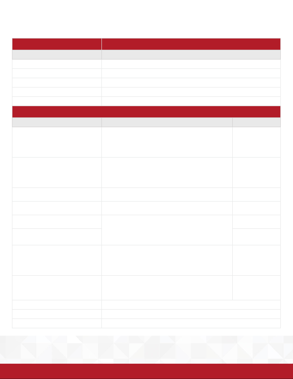
TVB-2 Technical Specications
MODEL TVB-2
COMPONENTS RESISTOR SPECIFICATION
120 K Ω 2.5KVAC / 50W / 1% ± 50ppm
1MΩ 3KVDC / 3W / 1% ± 50ppm
0.5Ω 350VDC / 2W / 5% ± 300ppm
49MΩ 100VDC / 50W / 1% ± 50ppm
100MΩ 100VDC / 25W / 1% ± 100ppm
GENERAL
TEST POINTS TEST CONDITION SPECIFICATIONS
PASS
ACW/DCW 2MΩ / 6W
1. ACW: 1240V, 10mA or DCW: 2121V, 5000uA
2. Maximum Voltage 2500V
3. Test duty cycle, OFF time = ON time x 2
4. Maximum ON time limit 30 seconds
5. Recommended 2s ramp time
FAIL
ACW/DCW 120kΩ / 50W
1. ACW: 1240V, 10mA or DCW: 2121V, 5000uA
2. Maximum Voltage 2300V
3. Test duty cycle, OFF time = ON time x 8
4. Maximum ON time limit 5 seconds
5. Recommended 2s ramp time
PASS
IR 4MΩ / 12W
FAIL
IR 1MΩ / 3W
1. IR: 500V, 2MΩ
2. Maximum Voltage: 2500V
1. IR: 500V, 2MΩ
2. Maximum Voltage 1000V
PASS
GC 0.5Ω / 2W
FAIL
1. GC: 0.1A, 1Ω
2. Maximum Current 1A
GC 2Ω / 8W
PASS
GB 50mΩ / 50W
1. GB: ≤ 30A, 100mΩ
2. Maximum Current 30A
3. Test duty cycle, OFF time = ON time x 6
4. Maximum ON time limit 5 seconds
5. Maximum resistance range at 30A is 200mΩ
FAIL
GB 200mΩ / 50W
1. Test Current 15A
2. Test duty cycle, OFF time=ON time x 6
3. Maximum ON time limit 10 seconds
4. Maximum resistance range at 30A is 200mΩ
ENVIRONMENT 32° F - 104° F (0° - 40° C)
2%
2%
2%
2%
5%
5%
5%
1
3%
1
DIMENSIONS 7.3” (W) x 5.75” (L) x 2.95” (H) , 186mm x 146mm x 75 mm
WEIGHT 1.55 lbs
1
Note: if the resistance is greater than 200mΩ you must reduce the test current to 10A in order to display the actual resistance reading.
1
Note: si la résistance est supérieure à 200mΩ vous devez réduire le courant de test par 10A an d’acher la valeur de la résistance réelle.
© Ikonix USA 2
Page 4
TVB-2 Instruction Sheet
Symbols Explanation:
Please refer to the instruction manual for specic warning or caution information to avoid personal injury or damage to the
product.
S’il vous plaît se référer au manuel d’instructions de mise en garde ou information sur la prudence pour éviter des blessures ou
des dommages au produit
To indicate hazardous voltages may be present.
Avertissement des tensions dangereuses qui peuvent être présentes
General Information
The TVB-2 is a go/no-go load box for verifying that the failure detectors of your Ikonix USA electrical safety testing instrument are
functioning properly. Use the TVB-2 daily before you begin performing Hipot, Insulation Resistance, Ground Bond and Ground
Continuity tests. The TVB-2 is not intended to comply with any specic safety agency standard.
Note: the trip setting may vary up to 10% of the set value based on the combined tolerances of the instrument and the components
used in the TVB-2.
Using the TVB-2
The TVB-2 load box consists of resistors of varying types that induce a PASS or FAIL condition depending on the test parameters that
are set in your electrical safety tester. The 8 banana jacks located on the top of the box can be used to apply the corresponding load to
the output of your tester. Each banana jack should be used for a particular type of test, which is outlined on the layout of the load box.
To setup a test, connect the high voltage or high current test lead of your electrical safety tester to one of the GC, GB, ACW/DCW, or IR
test points. Connect the return lead to the Return point. Ensure that the settings on your electrical safety tester are less than or equal to
the maximum recommended voltage, current and duty cycle settings of the TVB-2. When all connections have been made, press the
TEST button to begin the test. With the correct settings entered into the electrical safety tester, connecting the output leads to a PASS
terminal should result in a PASS. Connecting the output leads to a FAIL terminal should result in a FAIL.
Note: pay close attention to the maximum voltage and duty cycle limitations of each resistor. Applying voltages that are
higher than the recommended maximum setting or duty cycles greater than indicated can cause damage to the TVB-2.
Note: attention à la tension maximale et les limites du cycle de travail de chaque résistance. L’application de tensions plus
élevées que le réglage maximum recommandé ou cycles de travail supérieures à celles indiquées peut causer des dommages
à la TVB-2
© Ikonix USA 3
Page 5
TVB-2 Instruction Sheet
AC POWER
AC POWER
Ground Continuity Verication
1
RS232
T10A 250V
GND
115V~ /230V~
10A MAX., 50Hz/60HZ
CAT. II
GC
FAIL
PASS
2Ω
500mΩ
Max 1A
Max 1A
GB
FAIL
PASS
200mΩ
50mΩ
Max 50W
Max 50W
VERIFICATION LOAD BOX
Continuous Power Limitations - See Specifications
RETURN
ACW / DCW
FAIL
120KΩ
Max 2300V
FAIL
1MΩ
Max 1000V
IR
TVB-2
PASS
2MΩ
Max 2500V
PASS
4MΩ
Max 2500V
H.V.
CAUTION
HIGH VOLTAGE
5KV MAX.
GROUND
TEST
OUTPUT
TEST
OUTPUT
CURRENT
CH
H.V.
SENSE+
OUTPUT
SENSE
RETURN
REMOTE INTERFACE
-
SIGNAL OUTPUTSCANNER 1 SCANNER 2
SIGNAL INPUT
INPUT
2
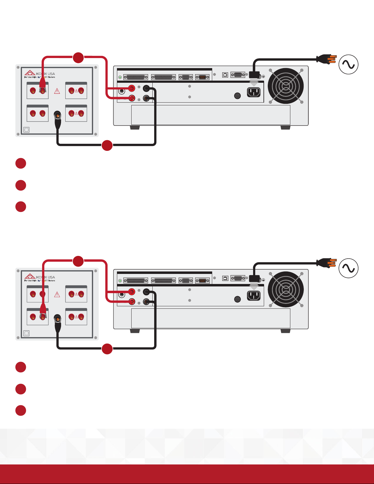
Connect the high current lead from the Sense + and CURRENT terminals on the instrument to the PASS terminal under the GC
1
terminals on the TVB-2 box.
Connect the return black alligator clip lead from the Sense and RETURN terminals on the instrument to the RETURN post on the
2
TVB-2 box.
Perform the necessary PASS/FAIL test per the Specications Table.
3
Ground Continuity Verication
1
RS232
T10A 250V
GND
115V~ /230V~
10A MAX., 50Hz/60HZ
CAT. II
GC
FAIL
PASS
2Ω
500mΩ
Max 1A
Max 1A
GB
FAIL
PASS
200mΩ
50mΩ
Max 50W
Max 50W
VERIFICATION LOAD BOX
Continuous Power Limitations - See Specifications
RETURN
ACW / DCW
FAIL
120KΩ
Max 2300V
FAIL
1MΩ
Max 1000V
IR
TVB-2
PASS
2MΩ
Max 2500V
PASS
4MΩ
Max 2500V
H.V.
CAUTION
HIGH VOLTAGE
5KV MAX.
GROUND
TEST
OUTPUT
TEST
OUTPUT
CURRENT
CH
H.V.
SENSE+
OUTPUT
SENSE
RETURN
REMOTE INTERFACE
-
SIGNAL OUTPUTSCANNER 1 SCANNER 2
SIGNAL INPUT
INPUT
2
Connect the high current lead from the Sense + and CURRENT terminals on the instrument to the PASS terminal under the GB
1
terminals on the TVB-2 box.
Connect the return black alligator clip lead from the Sense – and RETURN terminals on the instrument to the RETURN post on the
2
TVB-2 box.
Perform the necessary PASS/FAIL test per the Specications Table.
3
© Ikonix USA 4
Page 6
AC POWER
AC POWER
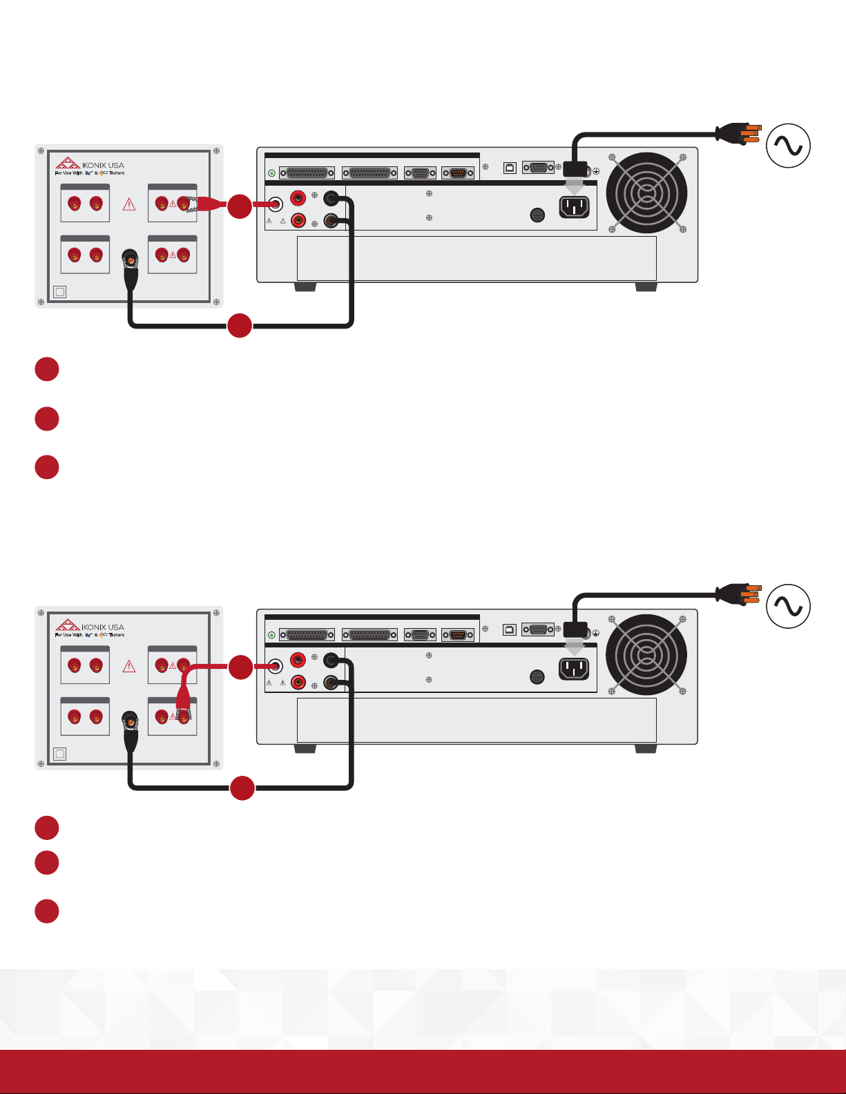
Hipot Verication
TVB-2 Instruction Sheet
RS232
T10A 250V
GND
115V~ /230V~
10A MAX., 50Hz/60HZ
CAT. II
GC
FAIL
PASS
2Ω
500mΩ
Max 1A
Max 1A
GB
FAIL
PASS
200mΩ
50mΩ
Max 50W
Max 50W
VERIFICATION LOAD BOX
Continuous Power Limitations - See Specifications
RETURN
ACW / DCW
FAIL
120KΩ
Max 2300V
FAIL
1MΩ
Max 1000V
IR
TVB-2
PASS
2MΩ
Max 2500V
PASS
4MΩ
Max 2500V
REMOTE INTERFACE
OUTPUT
SENSE
RETURN
-
SENSE+
H.V.
CAUTION
HIGH VOLTAGE
5KV MAX.
GROUND
TEST
OUTPUT
TEST
OUTPUT
CURRENT
CH
H.V.
1
SIGNAL OUTPUTSCANNER 1 SCANNER 2
SIGNAL INPUT
INPUT
2
Connect the high voltage lead from the instrument HV terminal to the PASS/FAIL terminal on the ACW/DCW terminals on the TVB-
1
2 box.
Connect the return black alligator clip lead from the Sense – and RETURN terminals on the instrument to the RETURN post on the
2
TVB-2 box.
Perform the necessary PASS/FAIL test per the Specications Table.
3
Insulation Resistance Verication
RS232
T10A 250V
GND
115V~ /230V~
10A MAX., 50Hz/60HZ
CAT. II
GC
FAIL
PASS
2Ω
500mΩ
Max 1A
Max 1A
GB
FAIL
PASS
200mΩ
50mΩ
Max 50W
Max 50W
VERIFICATION LOAD BOX
Continuous Power Limitations - See Specifications
RETURN
ACW / DCW
FAIL
120KΩ
Max 2300V
FAIL
1MΩ
Max 1000V
IR
TVB-2
PASS
2MΩ
Max 2500V
PASS
4MΩ
Max 2500V
REMOTE INTERFACE
OUTPUT
SENSE
RETURN
-
SENSE+
H.V.
CAUTION
HIGH VOLTAGE
5KV MAX.
GROUND
TEST
OUTPUT
TEST
OUTPUT
CURRENT
CH
H.V.
1
SIGNAL OUTPUTSCANNER 1 SCANNER 2
SIGNAL INPUT
INPUT
2
Connect the high voltage lead from instrument HV terminal to the PASS/FAIL terminal on the IR terminals on the TVB-2 box.
1
Connect the return black alligator clip lead from the Sense – and RETURN terminals on the instrument to the RETURN post on the
2
TVB-2 box.
Perform the necessary PASS/FAIL test per the Specications Table.
3
© Ikonix USA 5
Page 7
TVB-2 Instruction Sheet
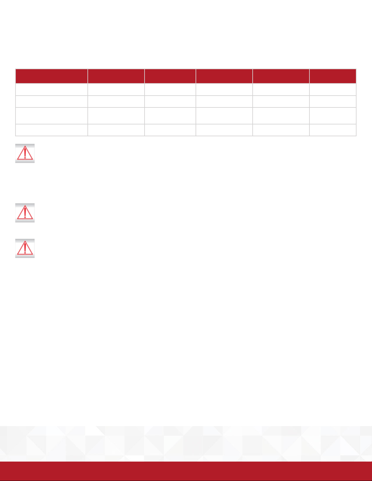
Recommended Test Parameter Conditions
The following table illustrates the resistor values and recommended test parameter settings for each type of test. Pay close attention to
the duty cycle limitations in the specications in order to avoid damaging the TVB-2 load box.
ACW DCW IR GC GB
PASS 2MΩ 2MΩ 4MΩ 500mΩ 50mΩ
FAIL 120 k Ω 120 kΩ 1MΩ 500mΩ 2MΩ
INSTRUMENT SETTINGS 1240V
10mA
RAMP 2s 2s N/A N/A N/A
WARNING:
The test voltages and currents which can cause harmful or fatal electric shock. To prevent accidental injury or death, these
safety procedures must be strictly observed when handling and using the test instrument.
Les tensions et les courants qui peuvent causer des chocs électriques dangereux ou fatal. Pour éviter les blessures
accidentelles ou la mort, ces procédures de sécurité doivent être strictement observées lors de la manipulation et l’utilisation
de l’instrument de test
Not rated for measurements within MEASUREMENT CATEGORIES II, III, or IV
N’est pas classé pour les catégories de surtension II, III ou IV
DO NOT TOUCH WHEN TESTING OR AFTER A MALFUNCTION HAS OCCURRED.
NE TOUCHEZ PAS LORS DE L’ESSAI OU APRÈS UN DYSFONCTIONNEMENT DU PRODUIT
CAUTION: Never connect TVB-2 to any mains circuit directly
ATTENTION: Ne jamais connecter directement le TVB-2 à un circuit d’alimentation.
2121V
5000uA
500V
2MΩ
1Ω 30A
100mΩ
MAINTENANCE:
To prevent electric shock do not remove the instrument cover. There are no user serviceable parts inside. Routine maintenance or
cleaning of internal parts is not necessary. Any external cleaning should be done with a clean dry or slightly damp cloth. Avoid the use
of cleaning agents or chemicals to prevent damage plastic parts or lettering.
ENTRETIEN:
Pour éviter les chocs électriques ne pas enlever le couvercle de l’instrument. Il n’y a aucune pièce reparable par l’utilisateur. L’entretien
de routine ou le nettoyage des pièces internes ne sont pas nécessaires. Tout nettoyage externe doit être fait avec un chion sec
ou légèrement humide. Éviter l’utilisation de produits de nettoyage ou des produits chimiques pour éviter d’eacer les lettres ou
d’abimer les pièces en plastique.
OPERATING ENVIRONMENT:
This instrument may be operated in environments with the following limits:
• Indoor Use Only
• Altitude: 2000 m
• Temperature: 0ºC to 40ºC
• Humidity: Maximum 80% RH at 31ºC decreasing to 50% RH at 40ºC
• Pollution Degree: 2
© Ikonix USA 6
Page 8

 Loading...