

Page 1

Quick Start Guide
OMNIA® II
Models 8204/8254, 8206/8256, 8207/8257
SAFETY CHECKLIST
Survey the test station. Make sure it is safe & orderly.
Always keep unqualifi ed/unauthorized personnel away from the test area.
Familiarize yourself with safety protocols in the event of a problem.
Exercise caution and never touch products or connections during a test.
Train operators. Never touch clips directly and always connect the return lead fi rst.
You should always know when a test is being performed.
WARNIN G: THIS GUIDE WA S CREATED FOR O PERATORS HAVING S OME FAMILI ARITY W ITH ELECTR ICAL SAF ETY
TESTING. AN ELECTRICAL SAFETY TESTER PRODUCES VOLTAGES AND CURRENTS THAT CAN CAUSE HARMFUL
OR FATAL ELECTRI C SHOCK. TO PRE VENT ACCIDENTAL I NJURY OR DE ATH, THES E SAFETY PR OCEDURES M UST
BE STRI CTLY OBSERVED WHEN HANDLING AN D USING A TEST INS TRUMENT. CONTACT US AT
INFO@ARISAFET Y.COM FOR MOR E INFO ON HOW TO GET TR AINED ON ELEC TRICAL SAF ETY TEST ING.
Page 2

INSTRUMENT SETUP
TEST
RESET
POWER
SIGNAL INPUT
SIGNAL OUTPUT
SCANNER 1
SCANNER 2
REMOTE INTERFACE
WARNING: LOCATE A SUITABLE TESTING AREA WITH A CLASS I GROUNDED OUTLET.
BE SURE THAT YOUR CLASS I OUTLET HAS BEEN TESTED FOR PROPER WIRING. READ
THE SAFETY CHECKLIST OF THIS GUIDE BEFORE STARTING TO TEST.
Connect the female end of the standard NEMA style power cord into the
1
input power receptacle on the rear panel of the instrument. Plug the male
end of the cord into a grounded power source.
8206/8256 8207/8257
REMOTE INTERFACE
-
REMOTE OUTPUT
EXTERNAL
CAUTION
HIGH VOLTAGE
SIGNAL OUTPUT
LLN
CAUTION
HIGH VOLTAGE
5KV
16A AX. MAX.
5KV MAX.
To Grounded
SCANNER 1 SCANNER 2
OUTPUT
SENSE+
H.V.
CURRENT
CAUTION
HIGH VOLTAGE
5KV MAX.
277V~MAX. 16A MAX.
SENSE
RETURN
N
Power Source
Connect the interlock disable key to the signal input connector on the
2
rear panel of the instrument. This is required to run a test.
REMOTE INTERFACE
-
REMOTE OUTPUT
EXTERNAL
CAUTION
HIGH VOLTAGE
SIGNAL OUTPUT
LLN
CAUTION
HIGH VOLTAGE
5KV
16A AX. MAX.
5KV MAX.
SCANNER 1 SCANNER 2
OUTPUT
SENSE+
H.V.
CURRENT
CAUTION
HIGH VOLTAGE
5KV MAX.
277V~MAX. 16A MAX.
SENSE
RETURN
N
RS232
SIGNAL INPUT
INPUT
DUT OUTPUTSDUT POWER I/P MD CIRCUITS
CASE CND PROBE HI PROBE LO
SIGNAL INPUT
INPUT
DUT OUTPUTSDUT POWER I/P MD CIRCUITS
CASE CND PROBE HI PROBE LO
GND
CAT. II
T10A 250V
115V~ /230V~
10A MAX., 50Hz/60HZ
8206/8256 8207/8257
RS232
GND
CAT. II
T10A 250V
115V~ /230V~
10A MAX., 50Hz/60HZ
Turn the POWER switch to ON.
3
®
OMNIA
SERIES
TESTRESET
POWER
MENU
OMNIA II 8257
2
ELECTRICAL SAFETY COMPLIANCE ANALYZER
Setup System
Setup Tests
Perform Tests
VERI-CKEK
Information
Menu
My
ABC DEF
1 2
GHI JKL MNO
4 5 6
PQRS TUV WXYZ
7
8 9
• 0 <
EXIT ENTER
3
- -
SCANNER STATUS
HI
H.V.
LO
CH
1 2 3 4 5 6 7 8
ON
GND
CAUTION
HIGH VOLTAGE
5KV MAX.
SENSE+ SENSE
CURRENT RETURN
H.V.
-
Page 3

TEST SETUP
EXIT
ENTER
Edit
EXIT
ENTER
Add
Delete
ADD NEW TESTS
START
OMNIA II 8257
the Setup Tests soft key.
SETUP TESTS
0001
File Name: 0001 TEST
Select the a Test Type.
Dielectric
Withstand
Insulation
Resistance
AC Ground Bond
DC Continuity
Line Leakage
Run Test
My
Menu
MENU
Setup System
Perform Tests
Setup Tests
VERI-CKEK
Information
1 2
4 5
7 8
• 0—<
EXIT ENTER
ABC3DEF
JKLGHI6MNO
TUVPQRS
SETUP TESTS
0001
My
Menu
Add
Edit
Delete
Prompt
File
ON
Fail Stop
My
Menu
Select the Add soft key.From the Main Menu select
ABC3DEF
AC - WITHSTAND
Voltage
Arc Sense
5
Frequency
10.00mA
60Hz
Arc Detect
OFF
0.00mA
Step Name
0.00mA
Defaults
More
1240 V
HI-Limit
HI-Limit
10.00mA
Total
WXYZ
9
- -
Real
LO-Limit
LO-Limit
0.00mA
Total
Real
Ramp Up
0.1s
Offset
Dwell Time
1.0s
Ramp Down
0.0s
Range :
Voltage 0V-5000V
Use the arrow keys to choose a
parameter to edit.
1 2
JKLGHI
MNO
4 5
6
TUVPQRS
WXYZ
7 8
9
- -
• 0—<
My
EXIT ENTER
Menu
ABC3DEF
AC - WITHSTAND
Voltage
Arc Sense
5
Frequency
10.00mA
60Hz
Arc Detect
OFF
0.00mA
Step Name
0.00mA
Defaults
More
1240 V
HI-Limit
HI-Limit
10.00mA
Total
Real
LO-Limit
LO-Limit
0.00mA
Total
Real
Ramp Up
0.1s
Offset
Dwell Time
1.0s
Ramp Down
0.0s
Enter the value for each parameter by
using the alpha/numeric key pad. Select
ENTER to save and go to the next parameter.
1 2
JKLGHI6MNO
4 5
TUVPQRS
WXYZ
7 8
9
- -
• 0—<
EXIT ENTER
My
Menu
AC - WITHSTAND
Voltage
Arc Sense
5
Frequency
10.00mA
0.00mA
0.00mA
Arc Detect
Step Name
Defaults
60Hz
OFF
More
My
Menu
1240 V
HI-Limit
HI-Limit
10.00mA
Total
Real
LO-Limit
LO-Limit
0.00mA
Total
Real
Ramp Up
0.1s
Offset
Dwell Time
1.0s
Ramp Down
0.0s
Select EXIT key followed by the ENTER
key to save your selection and return to
the Setup Tests screen.
EDIT TEST PARAMETERS
After a test has been set, you may edit the test parameters at any time.
ABC3DEF
SETUP TESTS
0001 ACW Settings
1240V 10.00mA
1.0s 0.000mA
0002 IR Settings
500V 0.00M
0.5s 0.05MΩ
START
File Name: 0001
Use the arrow keys to choose a test
to edit within the Setup Tests screen.
INSULATION RESISTANCE
Voltage
Ramp Down
DUT Output
0.0s
500 V
HI-Limit
Charge-Lo
0.00MΩ
LO-Limit
Ramp Up
Dwell Time
Delay Time
Range :
Voltage 0V-6000V
Use the arrow keys to choose a
parameter to edit.
Voltage
HI-Limit
LO-Limit
Ramp Up
Dwell Time
Delay Time
Range :
Hi-Limit 0.05MΩ - 50000MΩ 0=OFF
0.000uA
0.05MΩ
0.1s
0.5s
1.0s
INSULATION RESISTANCE
500 V
0.00MΩ
0.05MΩ
DUT Output
Ramp Down
0.0s
Charge-Lo
0.000uA
0.1s
0.5s
1.0s
Step Name
Defaults
Step Name
Defaults
Ω
OFF
My
Menu
OFF
My
Menu
Add
Edit
Delete
Prompt
File
Fail Stop
ABC3DEF
1 2
JKLGHI
4 5
TUVPQRS
7 8
• 0—<
EXIT ENTER
ABC3DEF
1 2
JKLGHI6MNO
4 5
TUVPQRS
7 8
• 0—<
EXIT ENTER
ON
Select EXIT key. You will return to the Setup Tests screen.
1 2
JKLGHI
MNO
4 5
6
TUVPQRS
WXYZ
7 8
9
- -
• 0—<
My
EXIT ENTER
Menu
0001 ACW Settings
1240V 10.00mA
1.0s 0.000mA
0002 IR Settings
500V 0.00M
0.5s 0.05MΩ
File Name: 0001
SETUP TESTS
Ω
Fail Stop
Select the Edit soft key.
MNO
6
WXYZ
9
- -
WXYZ
9
- -
INSULATION RESISTANCE
Voltage
Ramp Down
DUT Output
OFF
0.0s
500 V
HI-Limit
Charge-Lo
0.00MΩ
0.05MΩ
0.1s
0.5s
1.0s
Ω
0.000uA
SETUP TESTS
Step Name
Prompt
Fail Stop
Defaults
My
Menu
Add
Edit
Delete
File
ON
My
Menu
LO-Limit
Ramp Up
Dwell Time
Delay Time
Range :
Hi-Limit 0.05MΩ - 50000MΩ 0=OFF
Enter the value for each parameter by
using the alpha/numeric key pad. Select
ENTER to save and go to the next parameter.
0001 ACW Settings
1240V 10.00mA
1.0s 0.000mA
0002 IR Settings
500V 0.00M
0.5s 0.05MΩ
File Name: 0001
Add
Edit
Delete
Prompt
File
ON
1 2
4 5
7 8
• 0—<
ABC3DEF
1 2
JKLGHI
4 5
TUVPQRS
7 8
• 0—<
EXIT ENTER
My
Menu
ABC3DEF
JKLGHI6MNO
TUVPQRS
EXIT ENTER
MNO
6
WXYZ
9
- -
WXYZ
9
- -
3
Page 4
TEST SETUP
Setup Tests
Fail Stop
ON
Setup System
Prompt
Delete
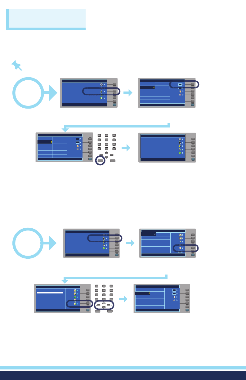
SET TEST SEQUENCES
Adding multiple tests to the same screen automatically creates a multiple step test
sequence.
Note: The test will run in a sequential order unless Single Step control is set to ON.
PERFORM TESTS
0001 ACW Settings
1240V 10.00mA
1.0s 0.000mA
0002 IR Settings
500V 0.00M
Ω
0.5s 0.05MΩ
File Name: 0001
Select the Single Step soft key
to toggle ON or OFF.
MENU
Setup System
Setup Tests
Perform Tests
VERI-CKEK
OMNIA II 8257
Single Step
Information
Load Files
OFF
Fail Stop
ON
Results
My
Menu
My
Menu
You will return to the Main Menu.
START
Select the EXIT key.
0001 ACW Settings
1240V 10.00mA
1.0s 0.000mA
0002 IR Settings
500V 0.00M
0.5s 0.05MΩ
File Name: 0001
MENU
Setup System
Setup Tests
Perform Tests
VERI-CKEK
Information
OMNIA II 8257
To perform a Single Step test,
select the Perform Tests soft key.
PERFORM TESTS
Ω
Single Step
Load Files
ON
Fail Stop
ON
Results
1 2
4 5
7 8
• 0—<
My
Menu
Menu
ABC3DEF
JKLGHI
TUVPQRS
EXIT ENTER
My
MNO
6
WXYZ
9
- -
SET TEST SEQUENCES
Test programs can be saved and loaded as fi les for easy recall of test conditions.
SETUP TESTS
0001 ACW Settings
1240 V 10.00mA
1.0s 0.000mA
File Name: 0001 TEST
If a test file is not already loaded,
load a file by selecting the File
soft key.
Add
Edit
Delete
Prompt
File
ON
Fail Stop
My
Menu
START
MENU
Setup System
Setup Tests
Perform Tests
VERI-CKEK
Information
OMNIA II 8257
From the Main Menu select
the Setup Tests soft key.
My
Menu
ABC3DEF
FILE SETUP
File Name:
0001
0002 TEST
0003 SEAN
0004
Use the arrow keys to choose the file.
Select the Load soft key to load the file.
New File
Save
Save As
Delete
Load
1 2
JKLGHI
MNO
4 5
6
TUVPQRS
WXYZ
7 8
9
- -
• 0—<
EXIT ENTER
My
Menu
PERFORM TESTS
0001 ACW Settings
1240 V 10.00mA
1.0s 0.000mA
0002 LLT Settings
10000uA
0.5s 0.0uA
File Name: 0002 TEST
The test file is loaded.
4
Single Step
Load Files
OFF
Fail Stop
ON
Results
My
Menu
Page 5
CREATE A NEW TEST FILE
Prompt
ON
Setup System
Prompt
Delete
Delete
START
MENU
Setup System
Setup Tests
Perform Tests
VERI-CKEK
Information
OMNIA II 8257
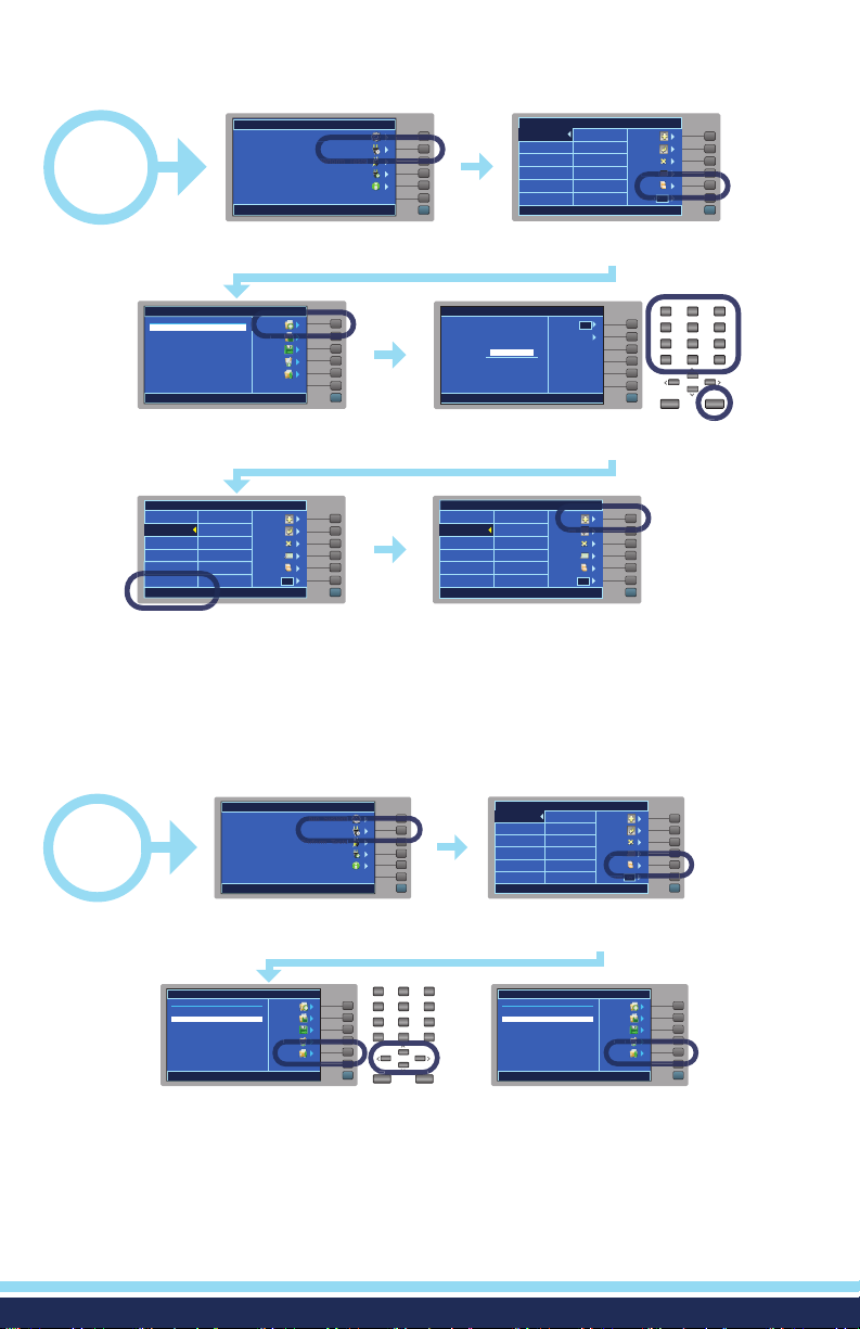
From the Main Menu select
the Setup Tests soft key.
FILE SETUP
File Name:
0002
New File
Save
Save As
Delete
Load
My
Menu
Select the New File soft key.
SETUP TESTS
0001
0002
File Name: 0002 TEST
Fail Stop
Add
Edit
Delete
Prompt
File
ON
My
Menu
This returns you to the Setup Tests
menu with a blank sequence. The
file name is displayed at the bottom.
SETUP TESTS
0001
Delete
Prompt
My
Menu
Fail Stop
Select the File soft key.
CREATE FILE
Caps Lock
ON
File Name:
0002 TEST
Symbol Key
My
Menu
Use the alpha/numeric key pad to give
the file a name. Select ENTER to save.
SETUP TESTS
0001
0002
File Name: 0002 TEST
Fail Stop
Add
Edit
Delete
Prompt
File
ON
My
Menu
You may begin setting up a full test
sequence by selecting the Add soft key.
Add
Edit
File
ON
1 2
4 5
7 8
• 0—<
EXIT ENTER
My
Menu
ABC3DEF
JKLGHI
TUVPQRS
MNO
6
WXYZ
9
- -
DELETE A TEST STEP
START
File Name:
0001
0002 TEST
0003 SEAN
0004
Select the Load soft key to load the file. Use the arrows to select the test
MENU
Setup System
Setup Tests
Perform Tests
VERI-CKEK
Information
OMNIA II 8257
From the Main Menu select
the Setup Tests soft key.
FILE SETUP
New File
Save
Save As
Delete
Load
My
Menu
ABC3DEF
1 2
JKLGHI
4 5
TUVPQRS
7 8
• 0—<
EXIT ENTER
My
Menu
SETUP TESTS
0001 ACW Settings
1240 V 10.00mA
1.0s 0.000mA
File Name: 0001 TEST
If a test file is not already loaded,
load a file by selecting the File
soft key.
MNO
6
WXYZ
9
- -
FILE SETUP
File Name:
0001
0002 TEST
0003 SEAN
0004
you would like to delete. Select
the delete soft key to delete the
Test Step.
5
Add
Edit
Delete
Prompt
File
ON
Fail Stop
My
Menu
New File
Save
Save As
Delete
Load
My
Menu
Page 6
TEST CONNECTIONS
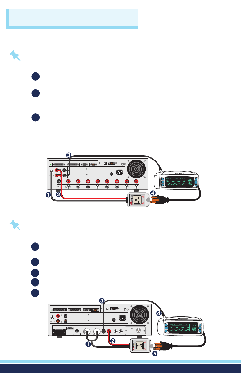
ADAPTER BOX CONNECTIONS (8204/8254)
The adapter box (P/N 38482) provides an easy way to connect the OMNIA II to a
device under test (DUT).
Note: If you are testing a Class I product, safety agencies may require you to perform
a Ground Bond test on the ground circuit of the DUT along with the Hipot test.
Using the output ports on the rear panel, plug the black high voltage lead in
1
the High Voltage terminal.
Plug the sense lead into the Sense (+) terminal. Plug the high current test
2
lead into the Current terminal. These two red leads act as the ground
connection.
Connect the ground return clip (P/N 38490) to the dead metal on the chassis
3
of the DUT. Plug the sense lead into the Sense (-) terminal. Plug the return
lead into the Return terminal. Always check to make sure a good connection
is made between the DUT and the return clip.
Plug the power cord of the DUT into the adapter box receptacle.
REMOTE INTERFACE
OUTPUT
SENSE+
SENSE
H.V.
CURRENT
RETURN
CAUTION
HIGH VOLTAGE
5KV MAX.
GROUND
TEST
OUTPUT
CH
G-COM. CH1 CH2 CH3 CH4 CH5 CH6 CH7 CH8
H.V.
CAUTION
HIGH VOLTAGE
TEST
5KV MAX.
OUTPUT
SIGNAL OUTPUTSCANNER 1 SCANNER 2
-
SIGNAL INPUT
RS232
INPUT
GND
CAT. II
T10A 250V
115V~ /230V~
10A MAX., 50Hz/60HZ
NL
5KVAC MAX.
6KVDC MAX.
5KVAC MAX.
6KVDC MAX.
HIGH VOLTAGE
HIGH VOLTAGE
CAUTION
CAUTION
ADAPTER BOX CONNECTIONS (8206/8256 & 8207/8257)
Note: Use the rear output terminal for connecting the adapter box (P/N 38578) on the
8206/8256 and 8207/8257 models.
Using the DUT output ports on the rear panel, plug the line lead from the
1
adapter box into the L terminal and the neutral lead into the N terminal.
Attach the red ground lead from the adapter box to the GND terminal.
2
Attach the black case return (P/N CBLHC40-10TL) lead into the case terminal.
3
Connect the ground return clip to dead metal on the chassis of the DUT.
4
Plug the line power cord from the DUT into the adapter box receptacle.
5
SCANNER 1 SCANNER 2
OUTPUT
SENSE+
H.V.
CURRENT
CAUTION
HIGH VOLTAGE
5KV MAX.
277V~MAX. 16A MAX.
277V~MAX. 16A MAX.
REMOTE INTERFACE
SIGNAL OUTPUT
-
SENSE
RETURN
LLN
EXTERNAL
EXTERNAL
CAUTION
CAUTION
HIGH VOLTAGE
HIGH VOLTAGE
LLN
CAUTION
CAUTION
HIGH VOLTAGE
HIGH VOLTAGE
16A AX. MAX.
16A AX. MAX.
5KV MAX.
5KV MAX.
N
N
REMOTE OUTPUT
REMOTE OUTPUT
RS232
SIGNAL INPUT
INPUT
DUT OUTPUTSDUT POWER I/P MD CIRCUITS
DUT OUTPUTSDUT POWER I/P MD CIRCUITS
CASE CND PROBE HI PROBE LO
CASE CND PROBE HI PROBE LO
5KV
5KV
GND
CAT. II
T10A 250V
115V~ /230V~
10A MAX., 50Hz/60HZ
NL
5KVAC MAX.
6KVDC MAX.
5KVAC MAX.
6KVDC MAX.
HIGH VOLTAGE
HIGH VOLTAGE
CAUTION
CAUTION
6
Page 7
TEST
RESET
POWER
TEST
RESET
POWER
TEST CONNECTIONS
WARNING: DO NOT TOUCH THE DEVICE UNDER TEST ONCE YOU START THE TEST.
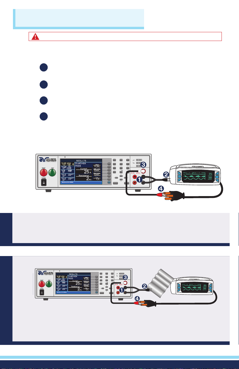
TEST LEAD CONNECTIONS
If you want you can use test leads to connect the OMNIA II to the DUT.
Plug the black return lead (P/N 38490) into the Return terminal. Plug black
1
sense lead into the Sense (-) terminal.
Attach the clip-terminated end of the return lead to the dead metal on
2
the chassis of the DUT.
Connect the high voltage lead (P/N 4040A-08) into the High Voltage
3
terminal on the front panel of the instrument.
Attach the high voltage lead to the current-carrying conductors of
4
the DUT.
Class I Product
®
OMNIA
SERIES
TESTRESET
POWER
ELECTRICAL SAFETY COMPLIANCE ANALYZER
My
Menu
1 2
GHI JKL MNO
4 5 6
PQRS TUV WXYZ
7
• 0 <
EXIT ENTER
ABC DEF
8 9
3
- -
SCANNER STATUS
HI
H.V.
LO
CH
1 2 3 4 5 6 7 8
ON
GND
CAUTION
HIGH VOLTAGE
5KV MAX.
SENSE+ SENSE
CURRENT RETURN
H.V.
-
Did you know? When performing a Ground Bond test on a Class I product
connect the red high current lead (P/N 38489) into the current terminal and red
sense lead into the sense (+) terminal. The clip at the other end will connect to the
ground pin of the DUT plug.
Class II Product
®
OMNIA
TESTRESET
POWER
ELECTRICAL SAFETY COMPLIANCE ANALYZER
SERIES
1 2
4 5 6
7
• 0 <
My
Menu
ABC DEF
GHI JKL MNO
PQRS TUV WXYZ
8 9
EXIT ENTER
3
- -
SCANNER STATUS
HI
H.V.
LO
CH
1 2 3 4 5 6 7 8
ON
GND
CAUTION
HIGH VOLTAGE
5KV MAX.
SENSE+ SENSE
CURRENT RETURN
H.V.
-
FOIL
Did you know? If necessary, a 10 x 20 cm piece of foil can be attached to the
enclosure to simulate a full hand contact to the DUT. This foil acts as the return
point. The return and sense (-) terminal are attached to the foil. Always check to
make sure you made a good connection between the DUT and the return clip.
7
Page 8
RESULTS
EXIT
ENTER
View the results from performed tests. Results include test type, reason for failure, and
test parameters.
ABC3DEF
START
PERFORM TESTS
0001 ACW Settings
1240 V 10.00mA
1.0s 0.000mA
0002 LLT Settings
10000uA
0.5s 0.0uA
File Name: 0002 TEST
Single Step
Load Files
OFF
Fail Stop
ON
Results
My
Menu
From the Perform Tests screen, use
the arrow keys to choose the file to
see the test results.
RESULTS
0001 ACW Settings
1240 V 10.00mA
1.0s 0.000mA
0002 LLT Settings
10000uA
0.5s 0.0uA
File Name: 0002 TEST
LLT
PASS
264.0
Leakage RMS
179.9
Voltage
Neutral
Reverse
Ground
Probe Ph-Pl
MC Volt RMS
179.6
mV
V
I-Maximum
uA
179.9
Time
s
1.0
uA
My
Menu
Results include test type, reason
for failure and test parameters.
1 2
JKLGHI
MNO
4 5
6
TUVPQRS
WXYZ
7 8
9
- -
• 0—<
EXIT ENTER
PERFORM TESTS
0001 ACW Settings
1240 V 10.00mA
1.0s 0.000mA
0002 LLT Settings
10000uA
0.5s 0.0uA
File Name: 0002 TEST
Select the EXIT key to return to the
Perform Tests screen
PERFORM TESTS
0001 ACW Settings
1240 V 10.00mA
1.0s 0.000mA
0002 LLT Settings
10000uA
0.5s 0.0uA
File Name: 0002 TEST
Single Step
Load Files
OFF
Fail Stop
ON
Results
Menu
Select the Results soft key.
ABC3DEF
1 2
JKLGHI
Single Step
Load Files
OFF
Fail Stop
ON
Results
4 5
TUVPQRS
7 8
• 0—<
EXIT ENTER
My
Menu
My
MNO
6
WXYZ
9
- -
Safety Is Our Only Focus
®
For additional information about these and other key features of the OMNIA® II, please consult the
full Operation and Service Manual or call us toll-free 1-800 -858-TEST (8378) or +1-847-367-4077
©2019 Associated Research • arisafety.com
FOLLOW US!
01/2019
 Loading...