

Page 1
Quick Start Guide
C
US
®
HypotMAX
Models 7705, 7710, 7715, 7720
SAFETY CHECKLIST
Survey the test station. Make sure it is safe & orderly.
Always keep unqualied/unauthorized personnel away from the test area.
Familiarize yourself with safety protocols in the event of a problem.
Exercise caution and never touch products or connections during a test.
TÜV Rheinland
Train operators. Never touch clips directly and always connect the return lead rst.
You should always know when a test is being performed.
WARNIN G: THIS GUIDE WA S CREATED FOR O PERATORS HAVING S OME FAMILI ARITY W ITH ELECTR ICAL SAF ETY
TESTING. AN ELECTRICAL SAFETY TESTER PRODUCES VOLTAGES AND CURRENTS THAT CAN CAUSE HARMFUL
OR FATAL ELECTRI C SHOCK. TO PRE VENT ACCIDENTAL I NJURY OR DE ATH, THE SE SAFETY P ROCEDURES M UST
BE STRI CTLY OBSERVED WHEN HANDLING AN D USING A TEST INS TRUMENT. CONTACT US AT
INFO@ARISAFET Y.CO M FOR MORE INFO ON HOW TO GET TRAIN ED ON ELECTRIC AL SAFET Y TESTING.
Page 2
FRONT PANEL CONTROLS
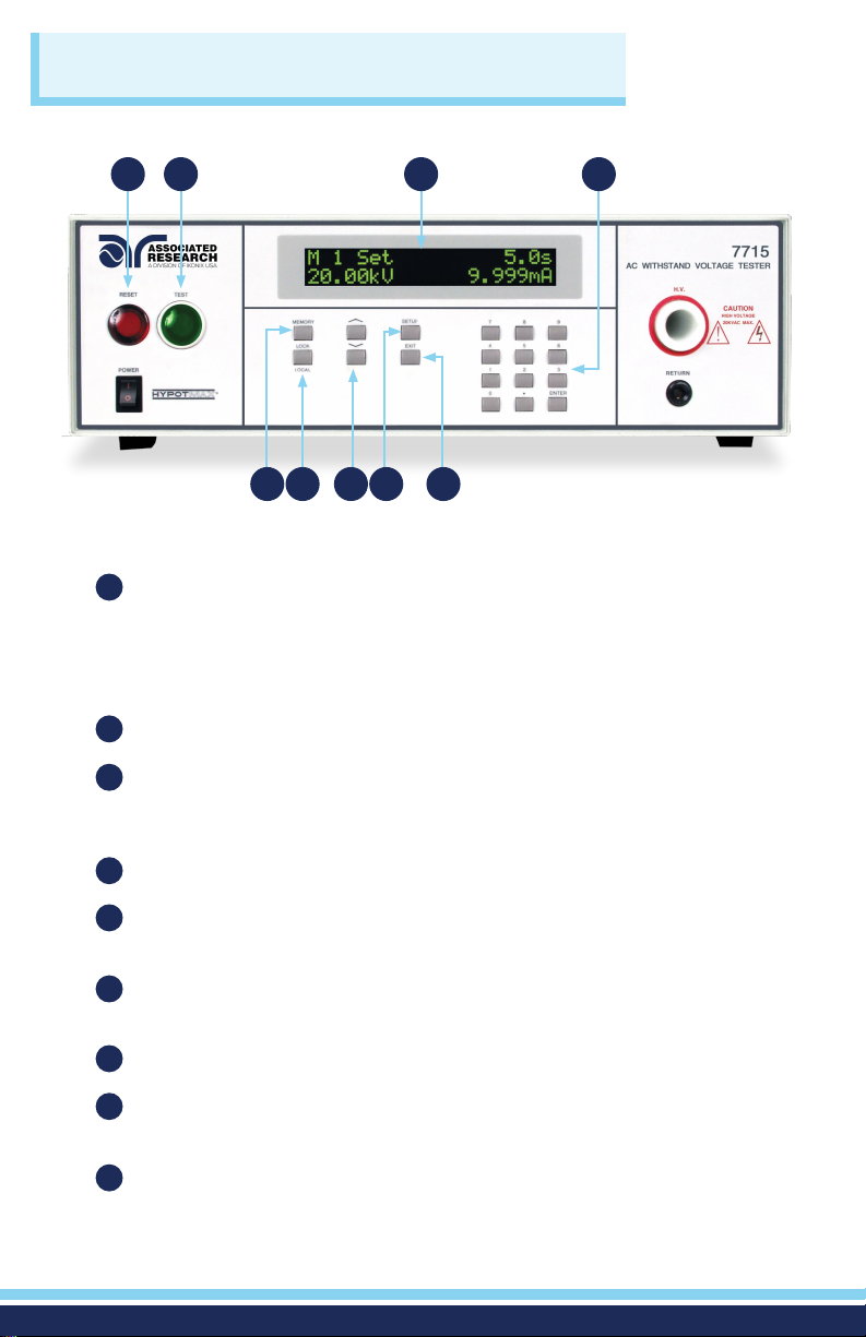
1 2 3 4
5 6 7 8 9
1
RESET BUTTON: Resets the instrument. If a failure condition occurs during a
test, pressing this button will reset the system, shut off the alarm and clear
the failure condition. The Reset button must be pressed before performing
another test or changing any of the setup parameters. This button also
serves as an abort signal to stop any test in progress.
2
TEST BUTTON: Starts a test.
LCD DISPLAY: The 2x20-character display indicates test function, memory
3
location, test parameter and failure type as well as test measurements
during a test.
DATA ENTRY KEYS: Keys to input numeric parameters.
4
MEMORY KEY: Use this key to select one of the 50 memories to modify or
5
run stored test parameters.
LOCK/LOCAL KEY: Enters key lockout mode. Use this key when you wish to
6
go from the Remote operation of the instrument to the Local mode.
7
UP-DOWN ARROW KEYS: Keys to cycle through test parameter setup.
SETUP KEY: Use this key to enter the setup menu and view or change the
8
display contrast, alarm volume, and PLC remote settings.
EXIT KEY: Use this key to exit any menu or to clear an unwanted entry in a
9
parameter eld.
2
Page 3
FRONT PANEL CONTROLS
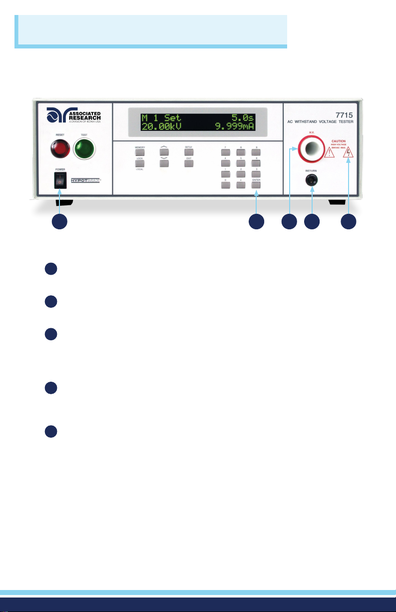
10
10
POWER SWITCH: Rocker style power switch with international ON ( | )
and OFF (0) markings.
ENTER KEY: Use the ENTER key to accept numeric data for parameter
11
settings.
HIGH VOLTAGE OUTPUT TERMINAL: Connector used to attach the high
12
voltage test lead, adapter box high voltage lead or test xture high voltage
lead to the instrument. This connection provides the high voltage used
during a Hipot test.
RETURN OUTPUT TERMINAL: Connector used to attach the return test lead,
13
adapter box return lead or test xture return lead to the instrument. This
connection provides the return current path.
HIGH VOLTAGE INDICATOR: This indicator ashes to warn the operator
14
that high voltage is present at the high voltage output terminal.
11 12 13
14
3
Page 4
BACK PANEL CONTROLS
1 52 3 4
6 7 8 9
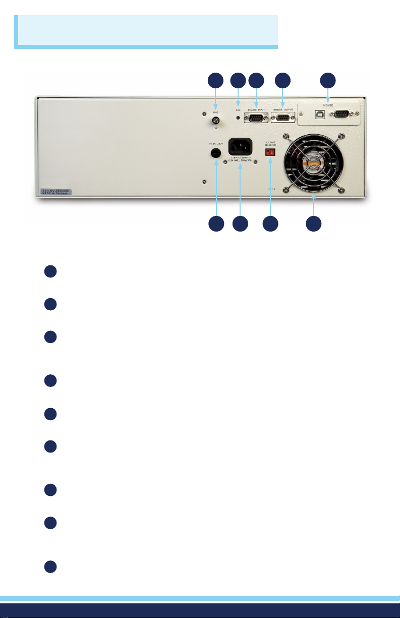
1
CHASSIS GROUND (Earth) CONNECTION: This terminal should be
connected to a good earth ground before operation.
2
CALIBRATION BUTTON: To put the instrument into the calibration mode push
this button and turn on the power switch simultaneously.
3
REMOTE SIGNAL INPUT: 9-Pin D-type subminiature male connector for
remote control of TEST, RESET, and REMOTE INTERLOCK DISABLE functions,
as well as MEMORY SELECTION.
REMOTE SIGNAL OUTPUT: 9-Pin D-type subminiature female connector for
4
monitoring PASS, FAIL, and PROCESSING output relay signals.
BUS INTERFACE: Standard connector for interconnection to the RS-232 Bus
5
interface. Optional IEEE 488 interface may be substituted for the RS-232.
FUSE RECEPTACLE: To change the fuse, unplug the power (mains) cord and
6
turn the fuse receptacle counter-clockwise. The fuse compartment will be
exposed. Please replace the fuse with one of the proper rating.
INPUT POWER RECEPTACLE: Standard IEC 320 connector for connection to a
7
standard NEMA style line power (mains) cord.
INPUT POWER SWITCH: Sets the line voltage conguration of the instrument.
8
In the left position it is set for 115 volt operation, in the right position it is set
for 230 volt operation.
THERMAL COOLING FAN: Runs continuously to cool the instrument.
9
4
Page 5
INSTRUMENT SETUP
WARNING: LOCATE A SUITABLE TESTING AREA WITH A THREE-PRONG, GROUNDED
OUTLET. BE SURE THAT YOUR THREE-PRONG OUTLET HAS BEEN TESTED FOR PROPER
WIRING. READ THE SAFETY CHECKLIST OF THIS GUIDE BEFORE STARTING TO TEST.
1. Choose the correct input line voltage on the rear panel of the instrument,
either 115VAC or 230VAC.
2. Connect the line cord into the rear of the instrument and plug the male end of
the cord into a grounded power source.
3. Plug the interlock connector into the Remote Signal Input connector on the
rear panel of the instrument. HypotMAX is equipped with a Remote Interlock
feature, which utilizes a set of closed contacts to enable the instrument’s
output. In order to perform a test, the interlock connector must be plugged
into the Remote Signal Input connection on the rear panel of the instrument.
4. Turn the POWER switch to ON.
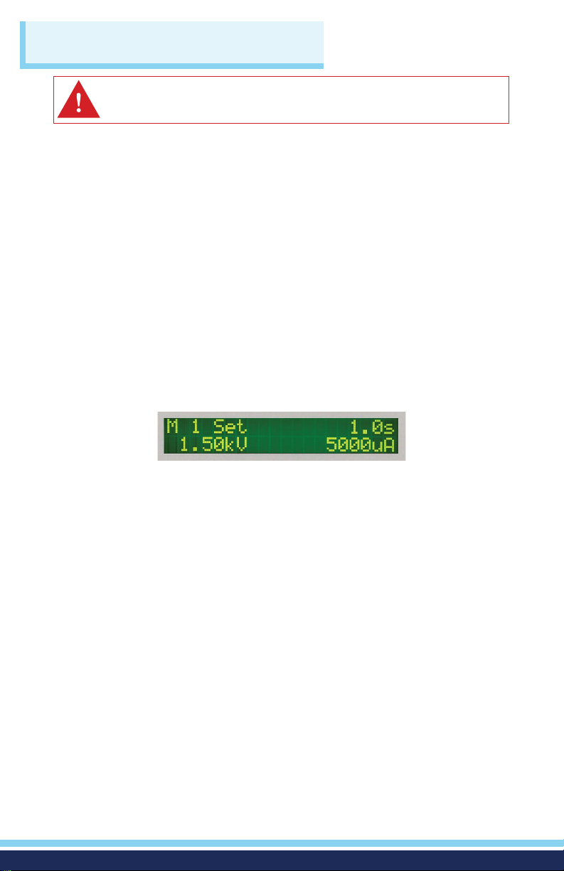
The initialization screen will appear. After three seconds the Perform Test Screen
will appear as shown below.
5
Page 6
CHANGING SYSTEM SETTINGS
ADDING A NEW TEST
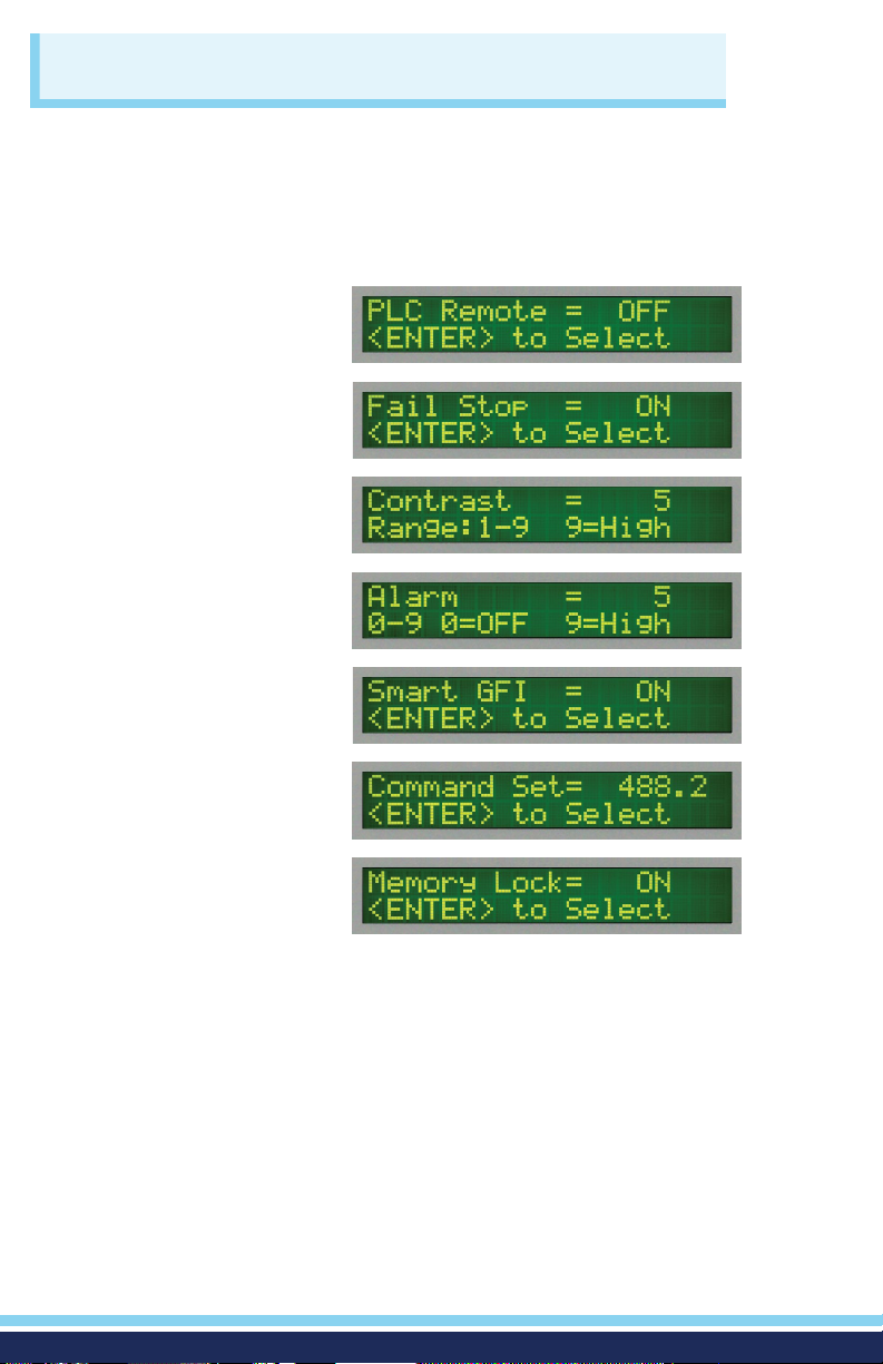
Press the SETUP key to progress through the menu of System Parameters.
Successive key presses will advance the menu forward. The sequential forward
menu items are:
PLC Remote
Fail Stop
Contrast
Alarm
Smart GFI
(Displayed with Option 01)
GPIB address
BUS Remote
Command Set
Memory Lock
Use the ENTER key and numeric keys to edit the System Parameters. Press the
EXIT key to return to the Perform Test screen. The system settings are global and
are not specic to any memory location.
SELECTING A MEMORY LOCATION
The HypotMAX is equipped with 50 memory locations, numbers 1 through 50.
Each memory location consists of 1 test and may be linked to perform up to 50
tests in sequence. To select the Memory Location press the MEMORY key. Use
the Numeric Keys to enter the memory location number, and then press the
ENTER key. The program will recall the test parameters stored in this location
and return to the operation mode automatically.
6
Page 7

CHANGING TEST SETTINGS
EDITING TEST PARAMETERS
If you wish to edit the test parameters, use the Up or Down arrow keys to
progress through the test parameters menu. The Down arrow key will advance
forward and the Up arrow key will advance backward. The sequence for
forward menu items are Voltage, HI-Limit, LO-Limit, Ramp-UP, Dwell Unit, Dwell
Time, Ramp-DOWN, Frequency (AC Model), Arc Detect, Arc Sense, Ramp-HI
(DC Models), Charge-LO (DC Models), and Connect. To edit the individual
parameters, use the numeric keys to enter the appropriate value. In some cases
the ENTER key will activate or deactivate a particular parameter such as
Connect. After all parameters have been adjusted, press the EXIT key to return
to the Perform Test screen.
TEST TYPE
ACW units
DCW units
PARAMETER
Voltage
HI-Limit (current)
LO-Limit (current)
Ramp-UP
Dwell Unit
Dwell Time
Ramp-DOWN
Frequency
Arc Detect
Arc Sense
Connect
Voltage
HI-Limit
LO-Limit
Ramp-UP
Dwell Unit
Dwell Time
Ramp-DOWN
Arc Detect
Arc Sense
Ramp-HI
Charge-LO
Connect
VALUE
1.24kVAC
5.000mA
0.000mA
0.3s
Second
1.0s
0.0s
60Hz
Off
5
OFF
1.5kVDC
5000μA
0.0μA
0.4s
Second
1.0s
0.0s
OFF
5
OFF
0.0μA
OFF
7
Page 8
CONDUCTING A TEST
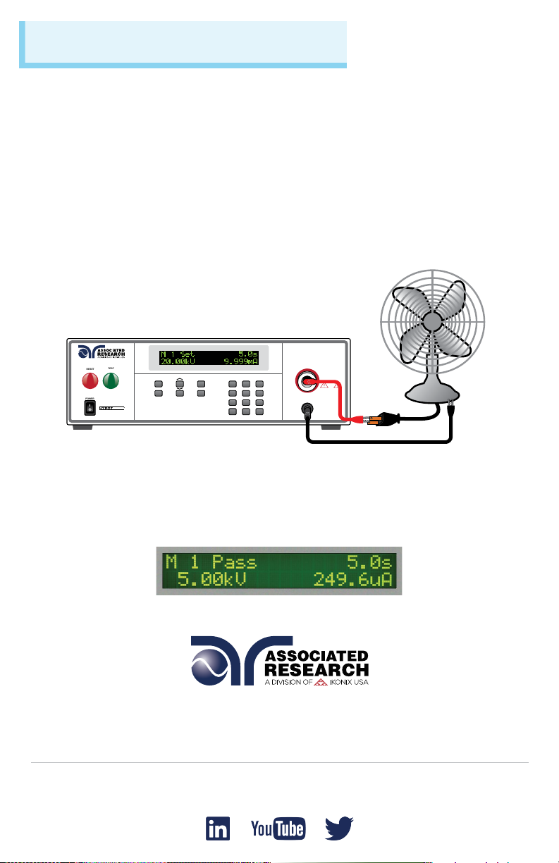
Plug the black return lead into the Return terminal on the front panel of the
instrument. Then connect the red high voltage lead into the High Voltage terminal
on the front panel of the instrument.
Attach the black clip-terminated end of the return lead to the dead metal on the
chassis of the DUT. Always check to make sure a good connection is made
between the DUT and the return clip.
Attach the red clip-terminated end of the high voltage lead to the current-carrying
conductors of the DUT. After the proper connections have been made, you can
initiate a test through the front panel of the HypotMAX by pressing the TEST
button.The red RESET button will abort a test in process.
7715
AC WITHSTAND VOLTAGE TESTER
TEST
RESET
POWER
MEMORY
LOCAL
MAX
SETUP
LOCK
7 8 9
EXIT 5 6
4
1 2 3
0 . ENTER
RESULTS
Press the ENTER key at the end of the test sequence to view results. Results can
also be reviewed at any time before the next test is executed by pressing the
ENTER key and then scrolling with the up and down arrow keys or by repeatedly
pressing the ENTER key. The results of the last test in the process will be followed
by the rst test when scrolling through the results.
H.V.
CAUTION
HIGH VOLTAGE
20KVAC MAX.
RETURN
For additional information about these and other key features of the HypotMAX®, please consult the
full Operation and Service Manual or call us toll-free 1-800-858-TEST (8378) or 1-847-367-4077
© Associated Research • arisafety.com
FOLLOW US!
3/2018
 Loading...