

Page 1

Operation and Service Manual
Hypot® Series
Models 3805, 3865, 3870 and 3880
Dielectric Withstand Voltage Instrument
AC/DC Hipot, Insulation Resistance, and Continuity Test Instruments
USB Interface standard on all models
Serial
————————
Item 40068
• Version 1.04
Printed January 4, 2021
A
R
N
R
T
A
Y
W
5
W
Y
A
T
R
N
R
A
28105 North Keith Drive, Lake Forest, IL, 60045 USA
© Ikonix USA 2021
RoHS 2
COMPLIANT
2011/65/EU
1
Page 2

DECLARATION OF CONFORMITY
Manufacturer: Associated Research
A Divison of Ikonix USA
Address: 28105 North Keith Drive
Lake Forest, IL 60045 USA
Product Name: Hypot® Dielectric Withstand Voltage Tester
Model Number: 3805/3865/3870
Conforms to the following Standards:
Safety: UL 61010-1:2012
UL 61010-2-030:2012
UL 61010-031:2007 R7.10
CAN/CSA-C22.2 NO. 61010 -1-12
CAN/CSA-C22.2 NO. 61010-031-07 + A1:2010
CAN/CSA-C22.2 NO. 61010-2-030-12
EMC: EN 61326 -1:2013 Class A
EN55011:2009+A1:2010 Group 1, Class A
EN 61000-3-2:2014/IEC 61000-3-2:2014 (Ed. 4.0)
EN 61000-3-3 :2013/IEC 61000-3-3 :2013 (Ed. 3.0)
EN 61326-1 :2013 (industrial locations)
EN 61000-4-2 :2009/IEC 61000-4-2 :2008 (Ed. 2.0)
EN 61000-4-3: 2006+A1: 2008+A2:2010
IEC 61000-4-3 :2006+A1 :2008+A2 :2010 (Ed. 3.2)
EN 61000-4-4 :2012/IEC 61000-4-4 :2012 (Ed. 3.0)
EN 61000-4-5 :2014/IEC 61000-4-5 :2014 (Ed. 3.0)
EN 61000-4-6 :2014/IEC 61000-4-6 :2013 (Ed. 4.0)
EN 61000-4-8 :2010IEC 61000-4-8 :2009 (Ed. 2.0)
EN 61000-4-11 :2004/IEC 61000 :4-11 :2004 (Ed. 2.0)
Supplementary Information
The product herewith complies with the requirements of the Low Voltage Directive 2014/35/EU, the EMC Directive 2014/30/EU
and the RoHS Directive 2011/65/EU with respect to the following substances: Lead (Pb), Mercury (Hg), Cadmium (Cd), Hexavalent
chromium (Cr (VI)), Polybrominated biphenyls (PBB), Polybrominated diphenyl ethers (PBDE), Deca-BDE included.
Last two digits of the year in which the CE marking was afxed: 17
The technical le and other documentation are on le with Associated Research
Joseph Guerriero
President
Associated Research
Lake Forest, Illinois USA
August 21, 2017
© Ikonix USA 2021 2
Page 3

DECLARATION OF CONFORMITY
Manufacturer: Associated Research
A Divison of Ikonix USA
Address: 28105 North Keith Drive
Lake Forest, IL 60045 USA
Product Name: Hypot® Dielectric Withstand Voltage Tester
Model Number: 3880
Conforms to the following Standards:
Safety: UL 61010-1:2012
UL 61010-2-030 :2012
UL 61010-031:2007 R7.10
CAN/CSA-C22.2 NO. 61010-031-07 + A1:2010
CAN/CSA-C22.2 NO. 61010 -1-12
CAN/CSA-C22.2 NO. 61010-2-030-12
EMC: EN 61326 -1:2013 Class A
EN 61000-3-3 :2013/IEC 61000-3-3 :2013
EN 61326-1 :2013 (industrial locations)
EN 61000-4-2 :2009/IEC 61000-4-2 :2008 (Ed. 2.0)
EN 61000-4-3: 2006+A1:2008+A2:2010
IEC 61000-4-3 :2006+A1 :2008+A2 :2010 (Ed. 3.2)
EN 61000-4-4 :2012/IEC 61000-4-4 :2012 (Ed. 3.0)
EN 61000-4-5 :2006/IEC 61000-4-5 :2014 (Ed. 3.0)
EN 61000-4-6 :2014/IEC 61000-4-6 :2013 (Ed. 2.0)
EN 61000-4-8 :2010IEC 61000-4-8 :2009 (Ed. 2.0)
EN 61000-4-11 :2004/IEC 61000 :4-11 :2004 (Ed. 2.0)
Supplementary Information
The product herewith complies with the requirements of the Low Voltage Directive 2014/35/EU, the EMC Directive 2014/30/EU
and the RoHS Directive 2011/65/EU with respect to the following substances: Lead (Pb), Mercury (Hg), Cadmium (Cd), Hexavalent
chromium (Cr (VI)), Polybrominated biphenyls (PBB), Polybrominated diphenyl ethers (PBDE), Deca-BDE included.
Last two digits of the year in which the CE marking was afxed: 17
The technical le and other documentation are on le with Associated Research
Joseph Guerriero
President
Associated Research
Lake Forest, Illinois USA
August 21, 2017
© Ikonix USA 2021 3
Page 4

Warranty Policy
Ikonix USA, certies that the tester listed in this manual meets or exceeds published manufacturing specications. This tester was
calibrated using standards that are traceable to the National Institute of Standards and Technology (NIST).
Your new tester is warranted to be free from defects in workmanship and material for a period of (5) years from date of shipment.
We aim to provide an amazing experience and quality testers that last a long time. If you’re not satised with your tester, return
it within 45 days for a full refund. Calibrate annually with us, or one of our authorized partners, and we’ll extend your warranty
an additional year for the service life of your tester, and at least ve years after discontinuation. If it breaks during that time,
we promise to x it for free (unless abuse or excessive damage is present). When your tester reaches the end of its service life,
we’ll responsibly recycle it and give you a discount on a replacement. Annual calibration and inspection must be made in each
successive year starting one year after the original purchase date in order to remain eligible for extended warranty coverage
beyond the standard warranty period (ve years).
Ikonix USA recommends that your tester be calibrated on a twelve-month cycle. A return material authorization (RMA) must be
obtained from Ikonix USA. To obtain an RMA please contact our Customer Support team at 1-847-367-4077 or visit arisafety.com.
Damages sustained as a result of improper packaging will not be honored. Transportation costs for the return of the tester for
warranty service must be prepaid by the customer. Ikonix USA will assume the return freight costs when returning the tester to
the customer. The return method will be at the discretion of Ikonix USA.
Except as provided, herein Ikonix USA makes no warranties to the purchaser of this tester and all other warranties, expressed or
implied (including, without limitation, merchantability or tness for a particular purpose), are hereby excluded, disclaimed and
waived.
Any non-authorized modications, tampering or physical damage will void your warranty. Elimination of any connections in the
earth grounding system or bypassing any safety systems will void this warranty. This warranty does not cover accessories not of
Ikonix USA manufacture. Parts used must be parts that are recommended by Ikonix USA as an acceptable specied part. Use of
non-authorized parts in the repair of this tester will void the warranty.
*5 year warranty is valid on any model purchased in 2021 or after.
Operator Modications
Any non-authorized modications, tampering or physical damage will void this warranty. Elimination of any connections in the
earth grounding system or bypassing any safety systems will void this warranty. This warranty does not cover accessories not of
Associated Research manufacture. Parts used must be parts that are recommended by Associated Research as an acceptable
specied part. Use of non-authorized parts in the repair of this instrument will void the warranty.
Associated Research will not be responsible for any injuries sustained due to unauthorized equipment modications or use
of parts not specied by Associated Research Instruments returned to Associated Research with unsafe modications will be
returned to their original operating condition at your expense.
© Ikonix USA 2021 4
Page 5

Table of Contents
Safety Precautions and Warning Symbols for High Voltage Testing ...........................................................................................6
Front Panel Controls (3805,3865,3870) ........................................................................................................................................7
Rear Panel Controls (3805,3865,3870) .........................................................................................................................................8
Front Panel Controls (3880) ..........................................................................................................................................................9
Rear Panel Controls (3880) .........................................................................................................................................................10
Setup Instructions ....................................................................................................................................................................... 11
Getting to Know Your Instrument ..............................................................................................................................................12
Main Menu ..................................................................................................................................................................................14
1. Setup System .............................................................................................................................................................................. 15
2. Setup Tests .................................................................................................................................................................................. 36
2.1 Setup AC Withstand Test .................................................................................................................................................37
2.2 Setup DC Withstand Test ................................................................................................................................................39
2.3 Setup Insulation Resistance Test .................................................................................................................................... 41
3. Perform Test ................................................................................................................................................................................ 47
4. Security ........................................................................................................................................................................................ 55
5. FailCHEK ...................................................................................................................................................................................... 57
6. MyMenu ....................................................................................................................................................................................... 60
Using Remote I/O and PLC Control ............................................................................................................................................ 61
Appendix A - Installation and Test Operator Information ........................................................................................................ 64
Installation .................................................................................................................................................................................. 64
1. Unpacking and Inspection ..................................................................................................................................................... 64
2. Safe Lifting and Carrying Instructions .................................................................................................................................64
3. Contents of the Carton .........................................................................................................................................................64
4. Preparation for Use ................................................................................................................................................................6 5
5. Power Cable ............................................................................................................................................................................ 65
Operating Environment ....................................................................................................................................................... 66
Storage and Shipment ......................................................................................................................................................... 66
Test Operator and Safety Considerations .......................................................................................................................... 66
1. Qualifications ......................................................................................................................................................................66
2. Safety Procedures ............................................................................................................................................................... 67
3. Dress ..................................................................................................................................................................................... 67
4. Medical Restrictions ........................................................................................................................................................... 67
5. Test Station .......................................................................................................................................................................... 67
Appendix B - Instrument Specifications .....................................................................................................................................69
Appendix C - Series Options ......................................................................................................................................................73
Appendix D - Remote Bus Interface: RS-232 .............................................................................................................................77
Appendix E - Replacement Parts List ........................................................................................................................................93
Appendix F - Calibration Procedure ...........................................................................................................................................95
NOTE: This is an interactive PDF, if viewing on a computer click on our quick links to jump quickly to that section.
Return to the Table of Contents by simply clicking on the page number with a above it in the bottom right corner.
© Ikonix USA 2021 5
Page 6
Safety Precautions and Warning Symbols for High Voltage Testing
GENERAL: Review this product and its related documentation for familiarization with safety markings and instructions
before operation.
This product is a Safety Class I instrument (provided with a protective earth terminal). Before applying power verify that the input
voltage to the instrument is 115VAC±10% or 230VAC±10% and the correct fuse is installed.
Product will be marked with this symbol when it is necessary to refer to the operation and service manual in order to
prevent injury or equipment damage.
S’il vous plaît se référer au manuel d’instructions de mise en garde ou information sur la prudence pour éviter des
blessures ou des dommages au produit
Product will be marked with this symbol when hazardous voltages may be present.
Avertissement des tensions dangereuses qui peuvent être présentes
Product will be marked with this symbol at connections that require earth grounding.
Le produit sera marqué de ce symbole au niveau des connexions qui nécessitent à la terre.
Caution and Warning Symbols
Calls attention to a procedure, practice, or condition that could possibly cause bodily
WARNING
Appelle l’attention sur une procédure, une pratique ou une condition qui pourrait causer des blessures corporelles ou la mort.
CAUTION
Appelle l’attention sur une procédure, une pratique ou une condition qui pourrait causer des blessures corporelles ou la mort.
WARNING
Le Hypot, des tensions et des courants qui peuvent causer des chocs électriques dangereux ou mortel. Pour éviter toute blessure
ou un décès accidentels, ces procédures de sécurité doivent être strictement respectées lors de la manipulation et l’utilisation de
l’appareil de contrôle.
injury or death.
Calls attention to a procedure, practice, or condition that could possibly cause damage
to equipment or permanent loss of data.
The Hypot produces voltages and currents that can cause harmful or fatal electric shock. To prevent
accidental injury or death, these safety procedures must be strictly observed when handling and using
the test instrument.
© Ikonix USA 2021
6
Page 7
Front Panel Controls (3805,3865,3870)
Hypot® Series
RESET
TEST
POWER DATA
BARCODE
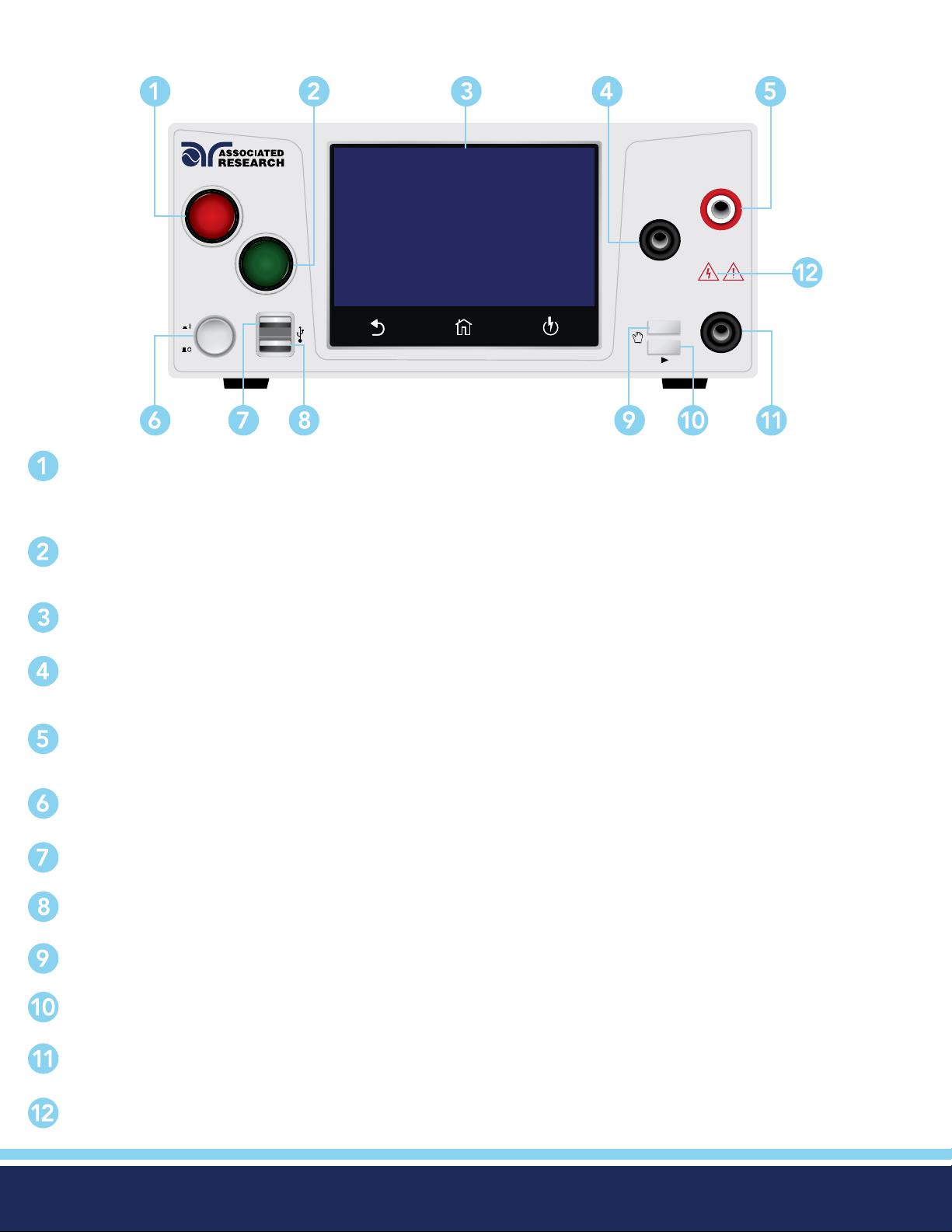
RESET BUTTON: Resets the instrument. If a failure condition occurs during a test, pressing this button will reset the
system, shut off the alarm and clear the failure condition. You must press the Reset button before performing another test
or changing any of the setup parameters. This button also serves as an abort signal to stop any test in progress.
DIELECTRIC WITHSTAND TESTER
HIGH VOLTAGE
RETURN
CAUTION
HIGH VOLTAGE
5KVAC MA X.
6KVDC MAX.
CONT.
My Menu / Select
CHECK
TEST BUTTON: This is a momentary contact switch used to start a test. Press the green button to turn on the high voltage
output when in test mode. The indicator lamp within the button will light when continuity is within limits for the built-in
continuity test.
TOUCH SCREEN GRAPHIC LCD: Displays all the information and allows full control of the instrument.
RETURN TERMINAL: Connector used to attach the return test lead, adapter box return lead or test xture return lead
to the instrument. This connection provides the return current path.
HIGH VOLTAGE OUTPUT TERMINAL: Connector used to attach the high voltage test lead, adapter box high voltage lead
or test xture high voltage lead to the instrument. This connection provides the high voltage used during a Hipot test.
POWER SWITCH: Powers the test instrument ON or OFF.
DATA USB PORT: This USB style port allows for connecting a USB ash drive to extract test and system data.
BARCODE USB PORT: This USB style port allows for connecting a barcode scanner.
MY MENU: Brings up the MyMENU screen.
TOGGLE: This button allows you to toggle between test les if you are wearing high voltage gloves.
CONT CHECK: Provides the connection for checking ground continuity.
HIGH VOLTAGE INDICATOR: Indicator ashes to warn the operator that high voltage is present at the high voltage
output terminal.
© Ikonix USA 2021
7
Page 8
Rear Panel Controls
SIGNAL OUTPUT SIGNAL INPUT
REMOTE INTERFACE
GND
T10A 250V
100-120~ / 200-240V~
360VA MAX., 50Hz / 60Hz
INPUTOUTPUT
CONT.
CHECK
RETURN H.V.
CAUTION
HIGH VOLTAGE
CAL.
USB
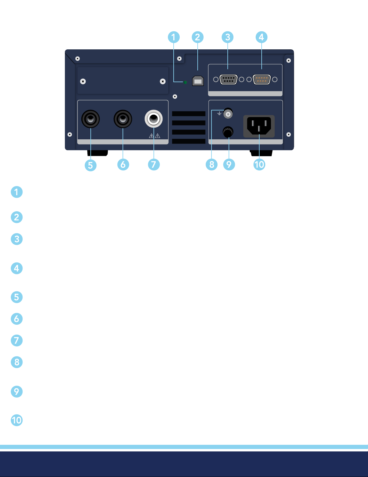
CALIBRATION BUTTON: o put the instrument into the calibration mode push this button and turn on the power switch
simultaneously.
USB CONNECTOR: USB port for serial communication. Refer to Appendix D: Remote Bus Interface.
REMOTE SIGNAL OUTPUT: 9 pin D subminiature female connector for monitoring PASS, FAIL, and PROCESSING output
relay signals.
REMOTE SIGNAL INPUT: 9-Pin D-type subminiature male connector for remote control of TEST, RESET, and REMOTE
INTERLOCK DISABLE functions, as well as MEMORY SELECTION..
CONTINUITY CHECK: 2nd continuity output connector in parallel with the front panel output.
RETURN: 2nd return output connector in parallel with the front panel connector.
HIGH VOLTAGE OUTPUT: 2nd high voltage output connector in parallel with the front panel connector.
CHASSIS GROUND EARTH TERMINAL: This safety ground terminal should be connected to a good earth ground
before operation.
FUSE RECEPTACLE: To change the fuse, unplug the power (mains) cord and turn the fuse receptacle counter-clockwise.
This will expose the fuse compartment. Please replace the fuse with one of the proper rating.
INPUT POWER RECEPTACLE: Standard IEC 320 connector for connection to a standard NEMA style line power (mains)
cord.
© Ikonix USA 2021
8
Page 9
Front Panel Controls (3880)
RESET
POWER
TEST
Data
Barcode
My Menu / Select
DIELECTRIC WITHSTAND TESTER
HIGH VOLTAGE
RETURN
CAUTION
HIGH VOLTAGE
5KVAC MA X.
CONT.
CHECK
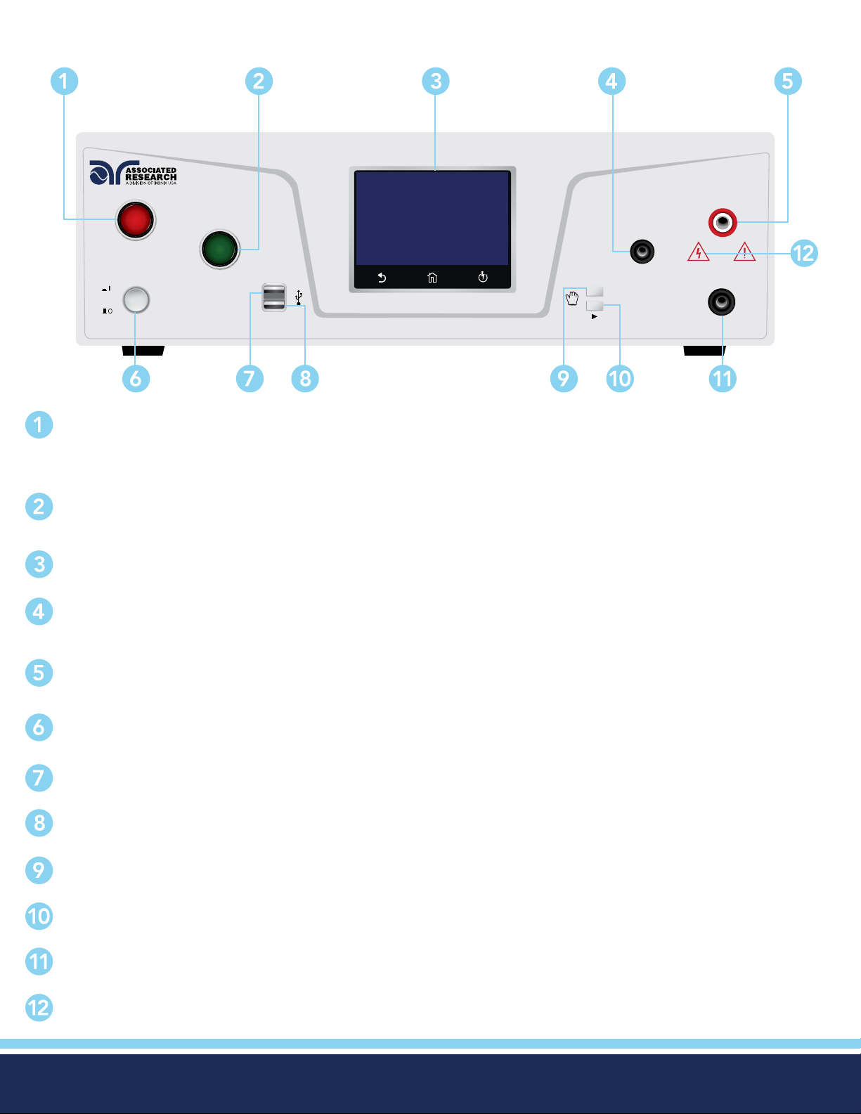
RESET BUTTON: Resets the instrument. If a failure condition occurs during a test, pressing this button will reset the
system, shut off the alarm and clear the failure condition. You must press the Reset button before performing another test
or changing any of the setup parameters. This button also serves as an abort signal to stop any test in progress.
TEST BUTTON: This is a momentary contact switch used to start a test. Press the green button to turn on the high voltage
output when in test mode. The indicator lamp within the button will light when continuity is within limits for the built-in
continuity test.
TOUCH SCREEN GRAPHIC LCD: Displays all the information and allows full control of the instrument.
Hypot® Series
RETURN TERMINAL: Connector used to attach the return test lead, adapter box return lead or test xture return lead
to the instrument. This connection provides the return current path.
HIGH VOLTAGE OUTPUT TERMINAL: Connector used to attach the high voltage test lead, adapter box high voltage lead
or test xture high voltage lead to the instrument. This connection provides the high voltage used during a Hipot test.
POWER SWITCH: Powers the test instrument ON or OFF.
DATA USB PORT: This USB style port allows for connecting a USB ash drive to extract test and system data.
BARCODE USB PORT: This USB style port allows for connecting a barcode scanner.
MY MENU: Brings up the MyMENU screen.
TOGGLE: This button allows you to toggle between test les if you are wearing high voltage gloves.
CONT CHECK: Provides the connection for checking ground continuity.
HIGH VOLTAGE INDICATOR: Indicator ashes to warn the operator that high voltage is present at the high voltage
output terminal.
© Ikonix USA 2021
9
Page 10
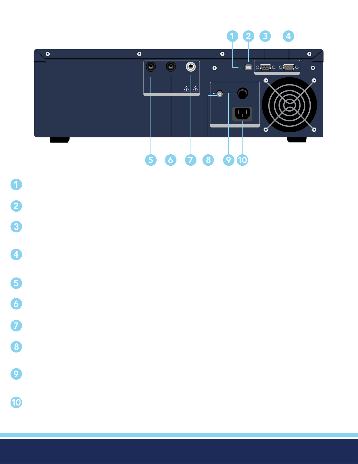
Rear Panel Controls (3880)
SIGNAL OUTPUT SIGNAL INPUT
USB
CAL.
CONT.
CHECK
RETURN
5KVAC MAX .
OUTPUT
H.V.
CAUTION
HIGH VOLTAGE
GND
T10A 250V
100-120~ / 200-240V~
1200VA MAX., 50Hz / 60Hz
INPUT
CALIBRATION ENABLE KEY: To enter the calibration mode press this key while the tester is being powered ON.
REMOTE INTERFACE
USB CONNECTOR: USB port for serial communication. Refer to Appendix D: Remote Bus Interface.
REMOTE SIGNAL OUTPUT: 9 pin D subminiature female connector for monitoring PASS, FAIL, and PROCESSING
output relay signals.
REMOTE SIGNAL INPUT: 9-Pin D-type subminiature male connector for remote control of TEST, RESET, and REMOTE
INTERLOCK DISABLE functions, as well as MEMORY SELECTION..
CONTINUITY CHECK: 2nd continuity output connector in parallel with the front panel output.
RETURN: 2nd return output connector in parallel with the front panel connector.
HIGH VOLTAGE OUTPUT: 2nd high voltage output connector in parallel with the front panel connector.
CHASSIS GROUND EARTH TERMINAL: This safety ground terminal should be connected to a good earth ground
before operation.
FUSE RECEPTACLE: To change the fuse, unplug the power (mains) cord and turn the fuse receptacle counter-clockwise.
This will expose the fuse compartment. Please replace the fuse with one of the proper rating.
INPUT POWER RECEPTACLE: Standard IEC 320 connector for connection to a standard NEMA style line power
(mains) cord.
© Ikonix USA 2021
10
Page 11
Setup Instructions
Power Up Sequence
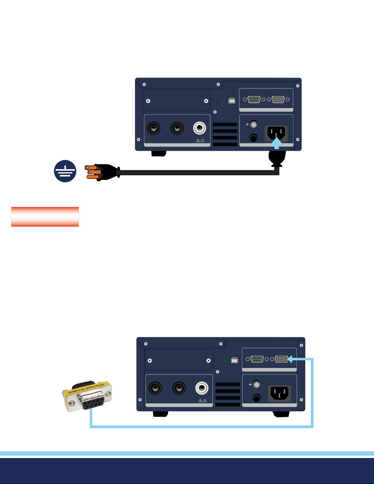
1. Connect the power input plug into its socket on the rear panel of the instrument. Connect the male end of the plug to the
outlet receptacle.
SIGNAL OUTPUT SIGNAL INPUT
USB
CAL.
REMOTE INTERFACE
To Grounded
Power Source
CONT.
CHECK
RETURN H.V.
HIGH VOLTAGE
CAUTION
GND
T10A 250V
100-120~ / 200-240V~
360VA MAX., 50Hz / 60Hz
INPUTOUTPUT
Only insert the main plug in a socket outlet with a protective ground (earth) contact. This protective
WARNING
ground must not be defeated by the use of an extension cord without a protective conductor.
La che principale ne doit être insérée dans une prise de courant avec une masse (terre) avec système de protection. Cette terre
de protection ne doit pas être vaincu par l’utilisation d’ une rallonge sans conducteur de protection.
2. Connect the Interlock Disable key to the Remote Input connector on the back panel of the instrument. This is required in order
to run a test. For more information on the interlock, see section for Remote Interlock.
SIGNAL OUTPUT SIGNAL INPUT
USB
CAL.
REMOTE INTERFACE
CONT.
CHECK
RETURN H.V.
HIGH VOLTAGE
CAUTION
GND
T10A 250V
100-120~ / 200-240V~
360VA MAX., 50Hz / 60Hz
INPUTOUTPUT
© Ikonix USA 2021
11
Page 12
3. Turn on the POWER switch located on the lower left hand side of the front panel. Upon powering the instrument up, a POWER
ON SELF TEST (POST) will automatically be performed. This test will check for the condition of the ram chips, PCB’s and other
critical components. The instrument screen will then default to the main menu.
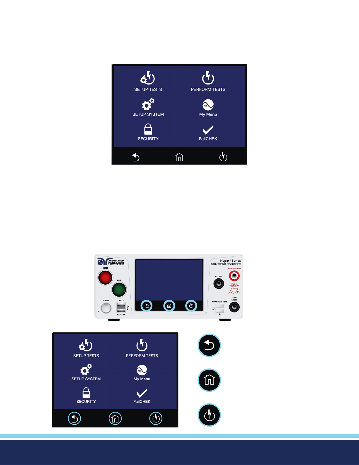
The default screen is the main menu screen of the instrument. From this screen you can access all the functions and settings of
the instrument:
Main Menu
Getting to Know Your Instrument
Using the Touch Screen
The touch screen display of the Hypot provides full control of the instrument. Use the he touch screen to setup system and test
parameters as well as security setup and calibration. Hypot’s touch screen functions just like any other touch screen.
Soft Keys
The Hypot touch screen has 3 functional keys: Back, Home and Perform Tests:
Use the Back key to return
to a previous menu.
© Ikonix USA 2021
Use the Home key to return
to the Main Menu.
Use the Perform Tests key to navigate
to the Perform Tests screen.
12
Page 13
Touc h
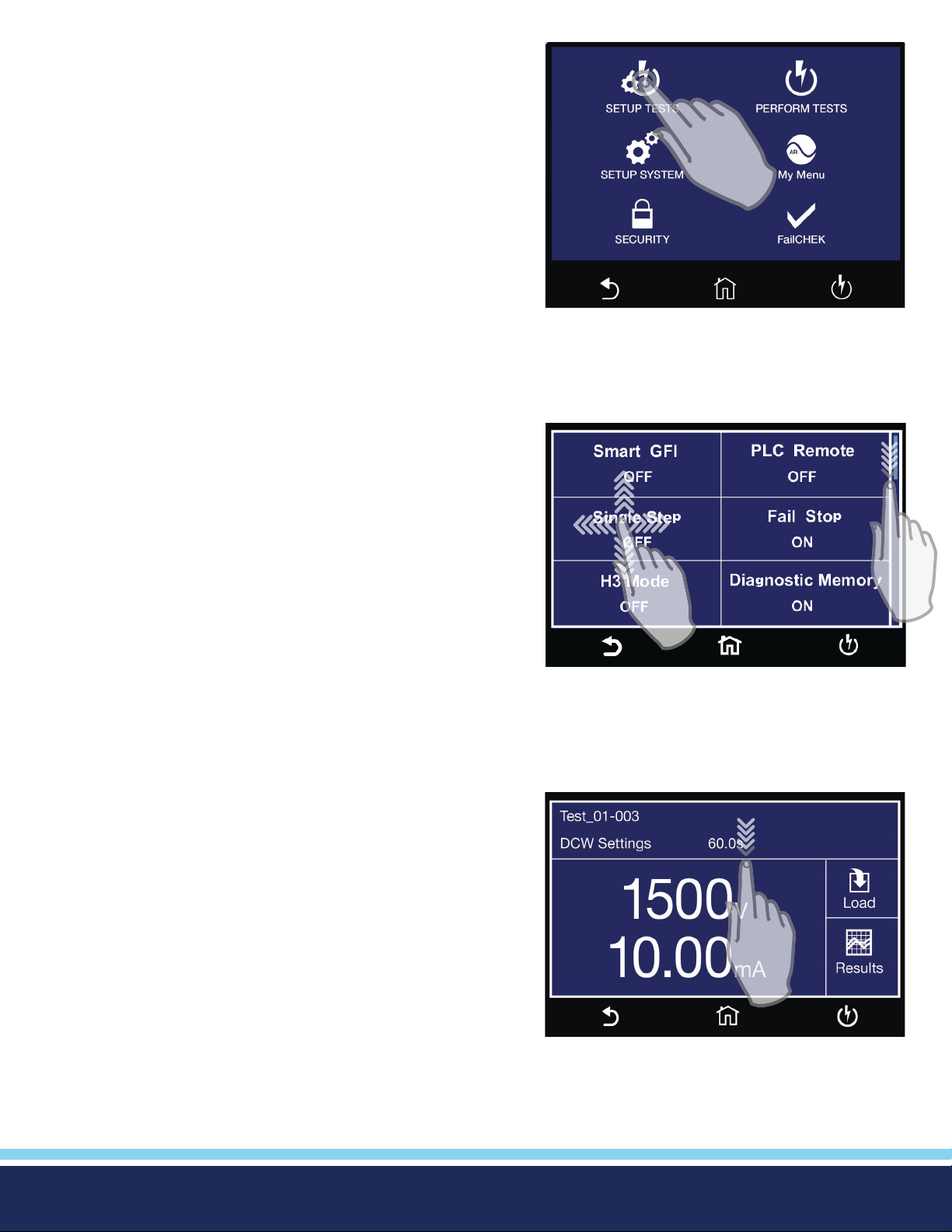
The various screens of the Hypot will display icons and parameters.
Touch the appropriate icon or parameter with the ngertip as shown
in the image to the right.
Scroll and Swipe
A scroll bar on the right side of the screen indicates that there are
additional parameters or features. To scroll up and down between
parameters touch the screen anywhere scroll upward or downward.
Swipe left to right in order to change parameters when setting up test
or system values.
Drag and Drop
You can drag and drop test les and steps on certain Hypot screens.
To use this feature simply touch and hold the test le, test step or
parameter. Drag the le to the appropriate location as shown in the
following screen to the right.
© Ikonix USA 2021
13
Page 14
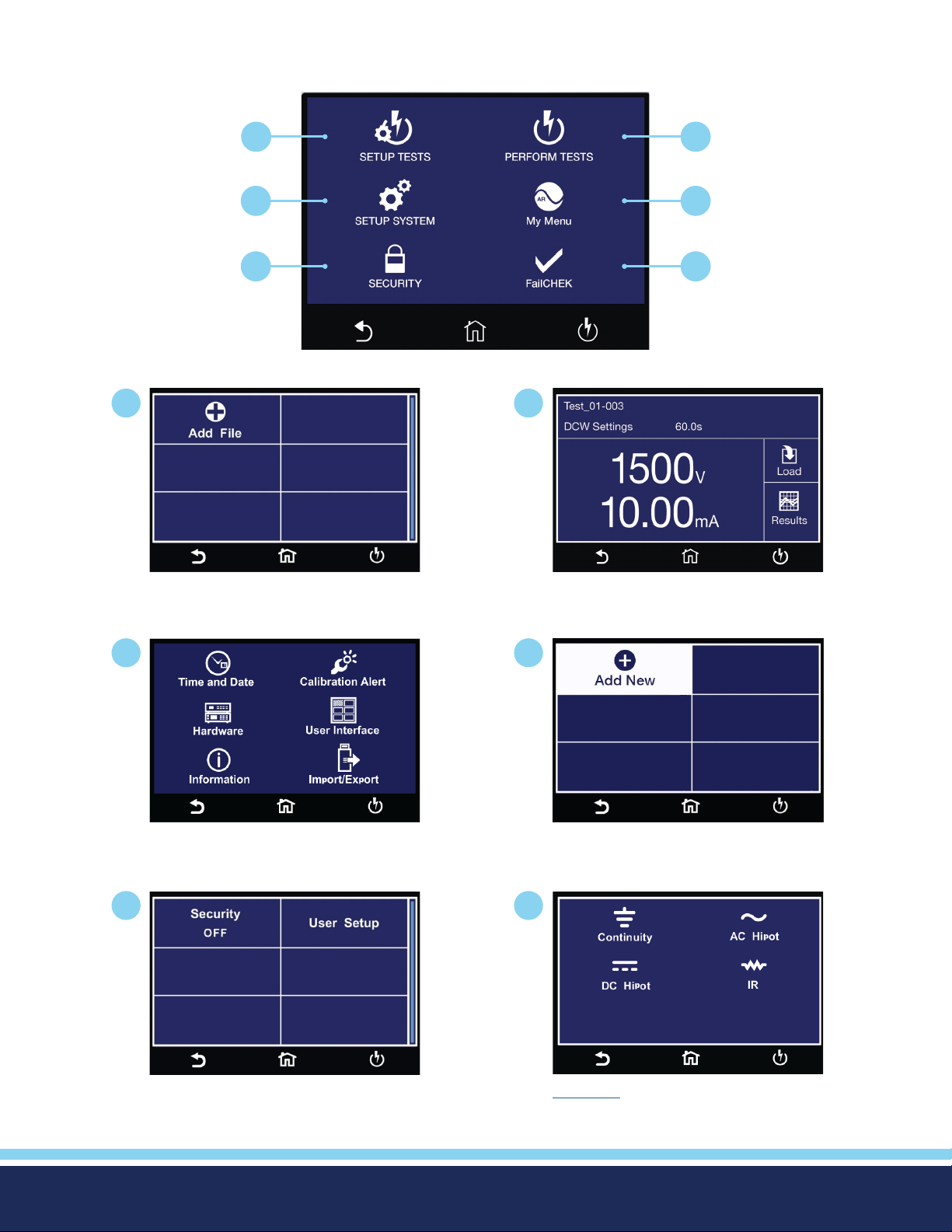
Main Menu
Upon powering up, the instrument will default to the Main Menu. The Main Menu is also the default home screen.
1
3
5
1
Setup Tests Screen - Create test les.
2
4
6
Main Menu
2
Perform Test Screen - Navigate to the
Perform Tests screen in order to run a
test sequence.
3
Setup System Menu - Instrument
global parameters such as time and
date, calibration and hardware.
5
Security Menu - Access instrument
lockout and security features.
4
My Menu Screen - User customized
menu.
6
FailCHEK Menu - Check the instrument’s
failure detectors
© Ikonix USA 2021
*Note – Details of each system and test parameter are listed in the relevant sections of the manual.
14
Page 15
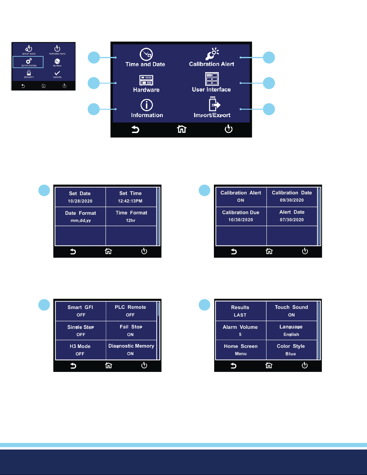
1. Setup System
From the default main menu touch the Setup System icon to enter the Setup System sub menu. This is where all System
Parameters can be edited:
Main Menu
1
1
3
2
4
5 6
Setup System Menu
2
3
Time and Date Menu Calibration Alert Menu
4
Hardware Menu User Interface Menu
Continued on next page
C
© Ikonix USA 2021
15
Page 16
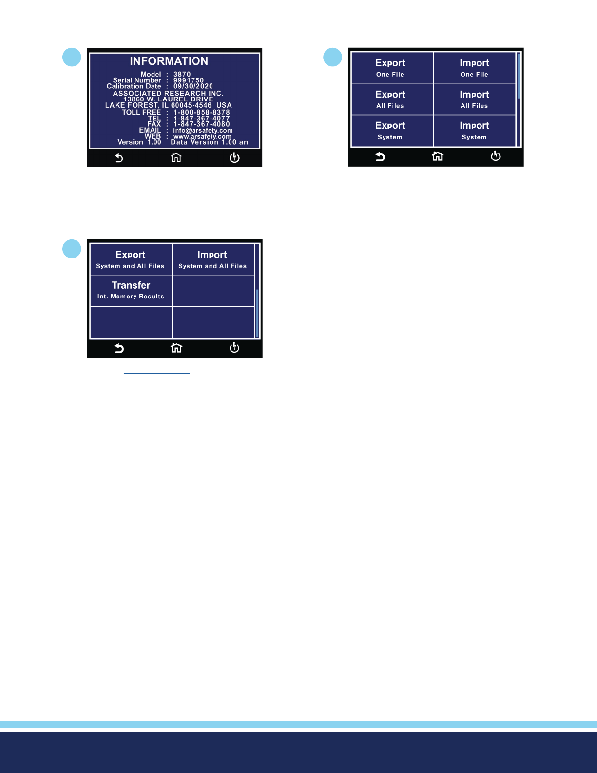
Setup System Continued
5
6b
6
Information Screen Import/Export Menu
Import/Export Menu 2
© Ikonix USA 2021
16
Page 17
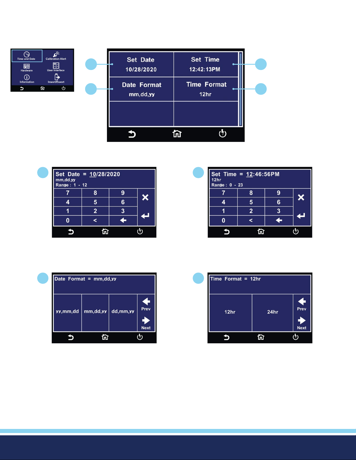
Time and Date
Time and Date menu allows the user to edit and save the System Time and Date. This time and date will be used to stamp the
test results data.
Setup System Menu
1
1
2
3 4
Time and Date Menu
2
Enter the current date to set System
Date.
3
Select the Date Format for System Date.
Enter current time to set System Time.
4
Select the Time Format for System
Time.
© Ikonix USA 2021
17
Page 18
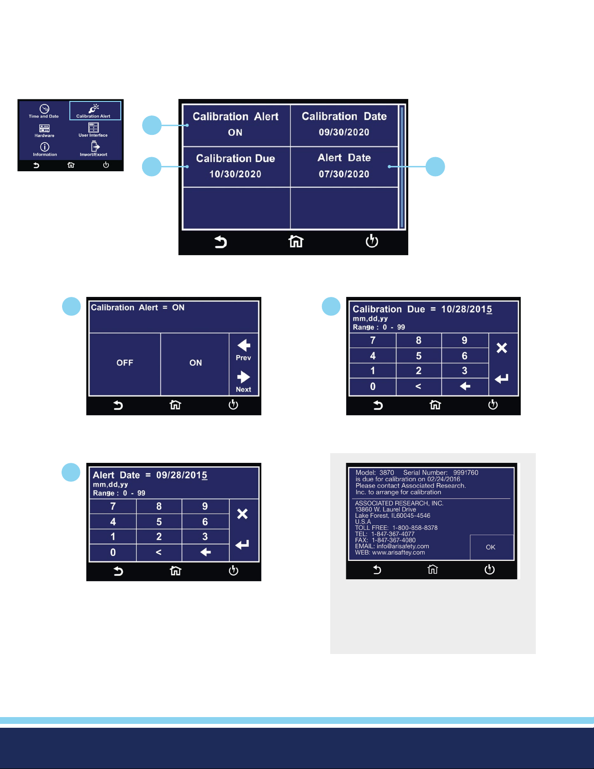
Calibration Alert
The Calibration Alert menu allows the user to setup alerts prior to the Calibration Due date. The user can also edit the Calibration
Due date. It is not recommended that the Calibration Due date be changed once the instrument has been calibrated. Associated
Research recommends annual calibrations for all models.
1
Setup System Menu
2 3
Calibration Alert Menu
1 2
Select Calibration Alert ON or OFF.
Enter a Calibration Due date.
3
Enter a Calibration Alert Date.
© Ikonix USA 2021
The above Calibration Alert screen will
be displayed upon powering up the
instrument, on and after the Calibration
Alert Date. This screen will display the
Calibration Due Date of the instrument.
18
Page 19
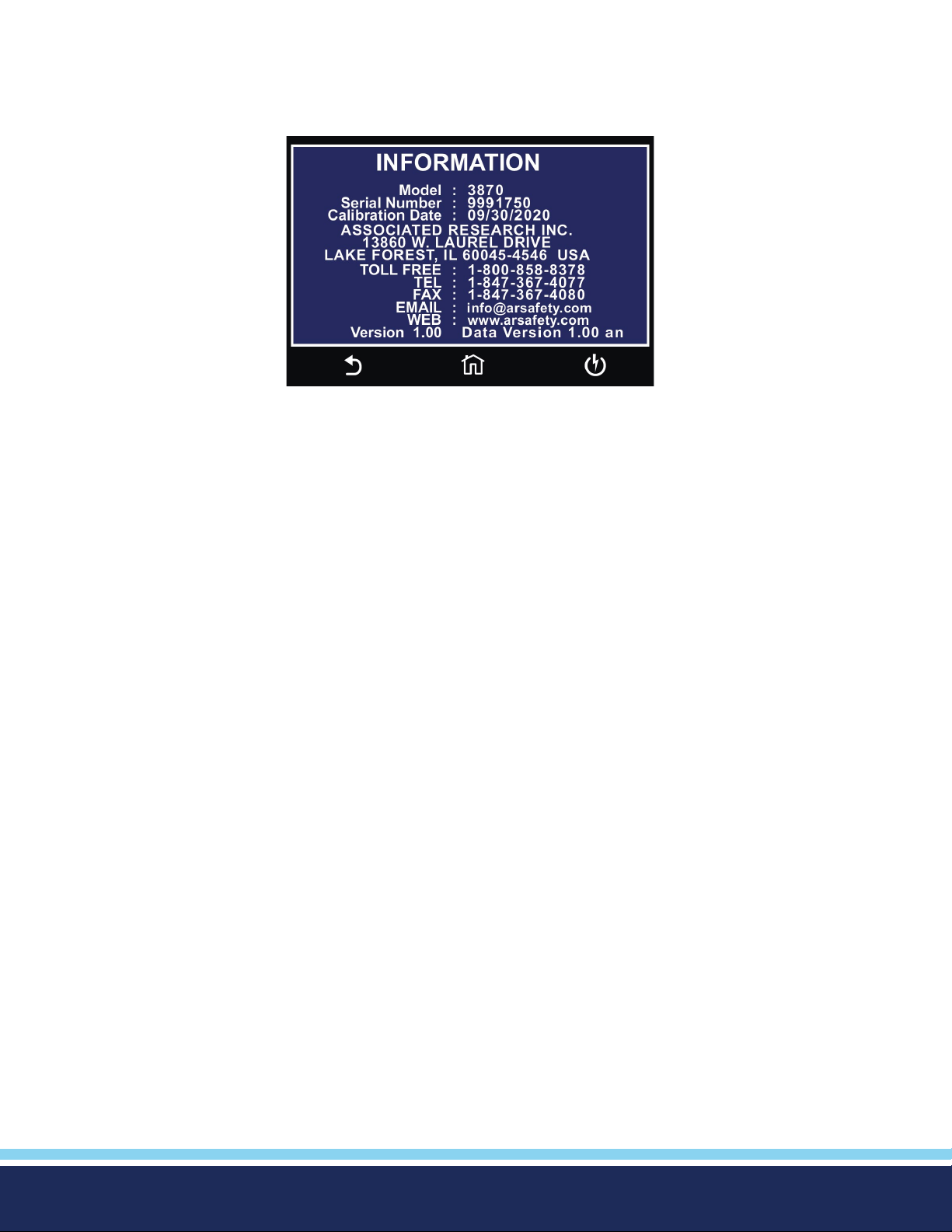
Information Screen
The Information screen displays all instrument information including: Model Number, Serial Number, Calibration Date, Company
Information and Firmware Version.
© Ikonix USA 2021
19
Page 20
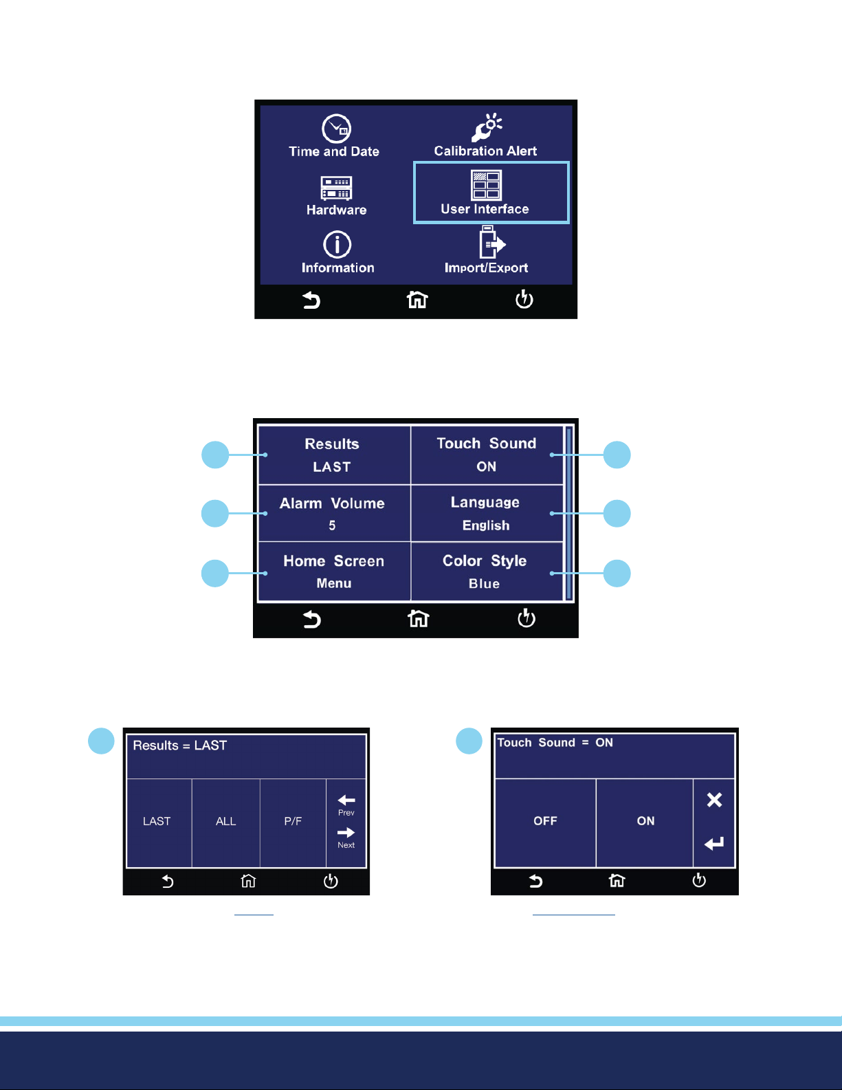
User Interface
The User Interface menu allows the user to edit Results, Touch Sound, Alarm Volume, Language, Home Screen &
Color Style parameters.
Setup System Menu
1
1
3
2
4
5 6
User Interface Menu
2
Select end of test Result Screen. Select Touch Sound ON or OFF.
© Ikonix USA 2021
Continued on next page
20
C
Page 21
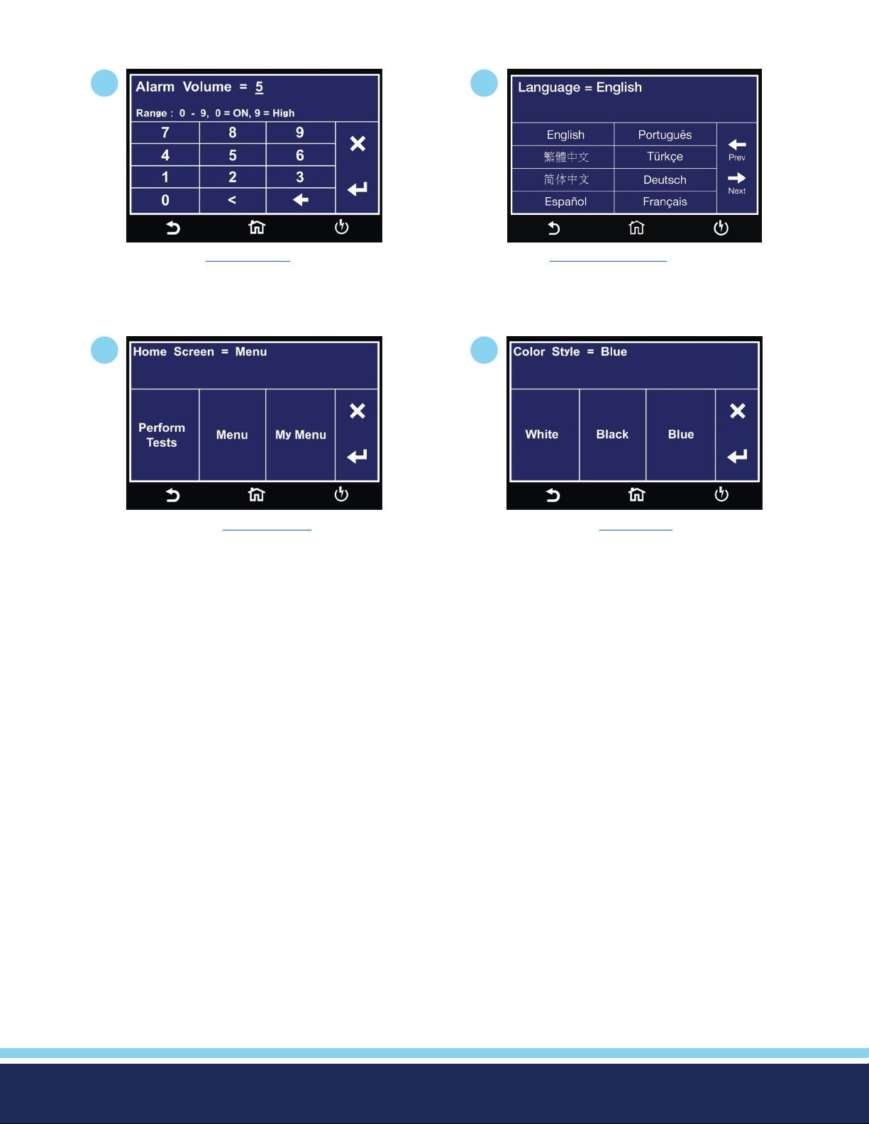
User Interface Continued
3
Enter Alarm Volume level.
5
4
Select System Language.
6
Select start up Home Screen.
Select System Color Style.
© Ikonix USA 2021
21
Page 22
User Interface Parameter Descriptions
Descriptions of User Interface parameters are listed in the following table:
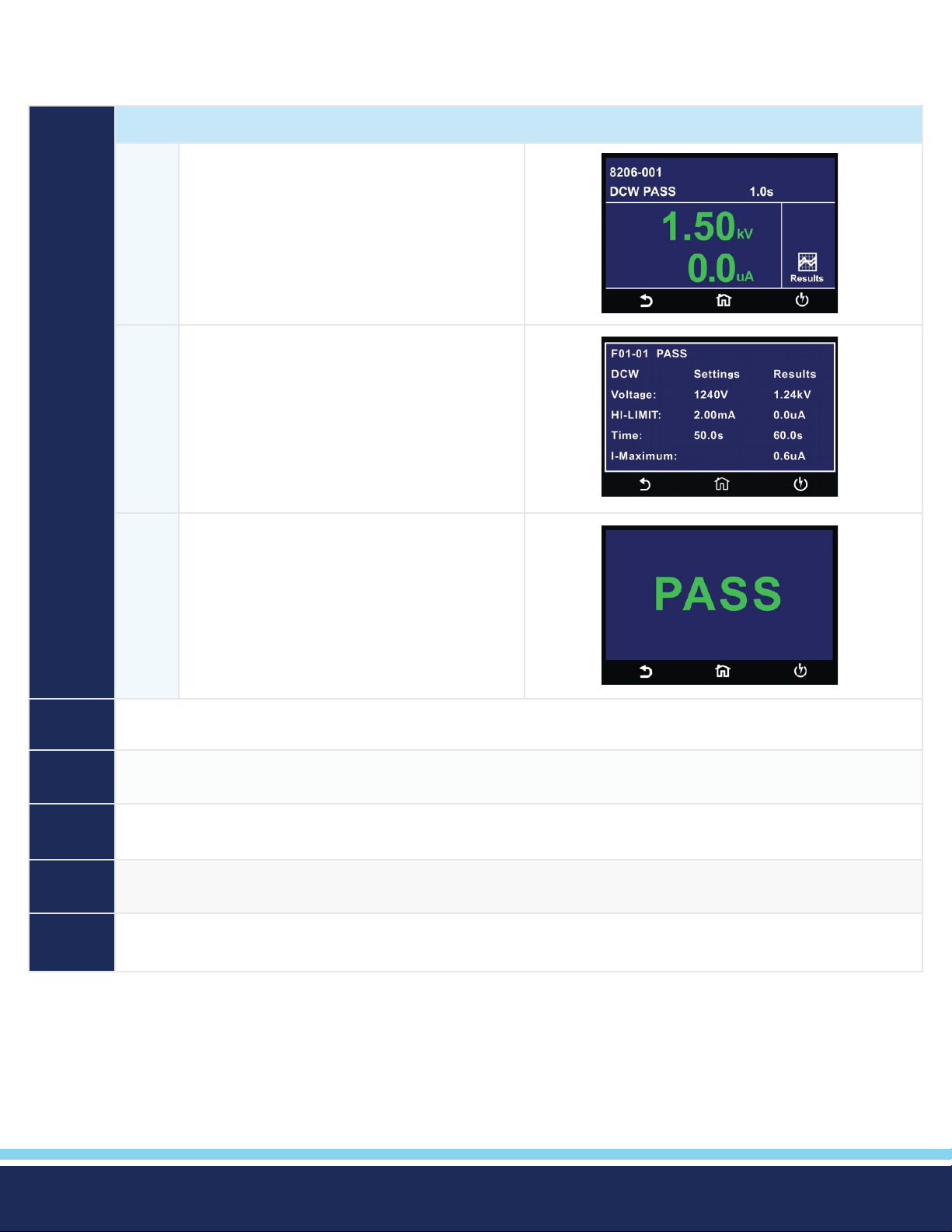
RESULT Select how the test results will be displayed at the end of a test or test sequence.
LAST The results of the last step performed will be
displayed on the Perform Tests screen. There
will not be a change in appearance or special
screen displayed in this mode
ALL Results summary screen will be displayed at the
end of the test or sequence of connected steps
displaying the results of all of the steps.
P/F Pass or Fail screen will be displayed at the end
of the test.
Touch
Sound
Alarm
Volume
Language Set the instrument display in the desired language. The available languages on the Hypot instruments are
Home
Screen
Color
Style
Set the instrument to emit a short audible beep anytime the screen is touched. Select between ON or OFF.
Set the instrument alarm volume. The numbers corresponding to the different volume settings are 0 through 9, 0
meaning the volume is off, and 9 being the loudest setting.
English, Chinese, Simplied Chinese, German, French, Turkish, Portuguese and Spanish.
Set the default screen upon instrument power up. Choose between Perform Test, Menu or My Menu.
Set the color style of the touch screen.
© Ikonix USA 2021
22
Page 23
Import/Export
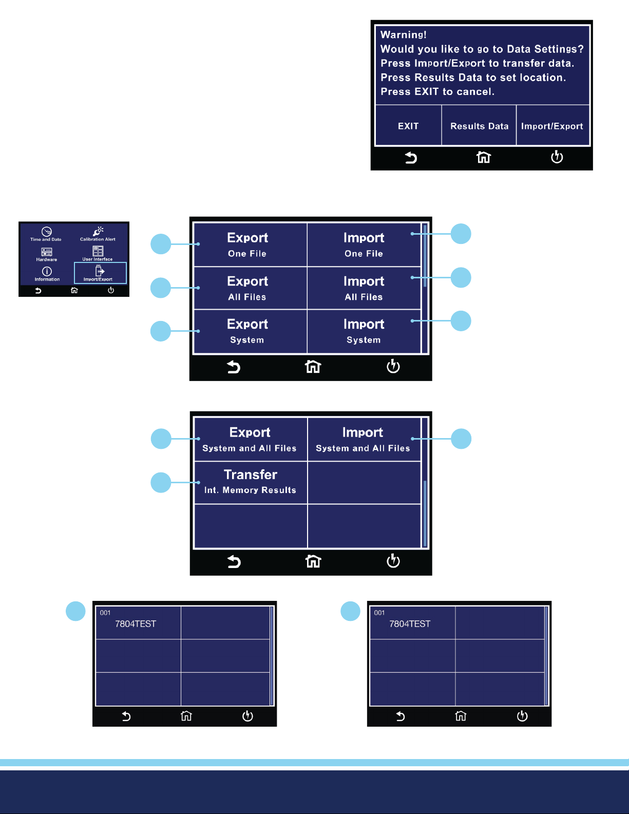
Insert USB disk into Data port and the following screen will appear.
Select Import/Export to use the Import/Export menu to transfer data.
Select Result Data to go to Result Data settings menu. Please refer to
the Results Data section of this manual.
The Import/Export menu allows the user to import or export System and Test Files from a USB ash drive into the instrument
memory. The Import/Export menu will only appear under the Hardware menu if a USB ash drive is inserted into the Data port
on the front panel of the instrument.
2
1
4
3
Setup System Menu
6
5
1
7
9
Import/Export Menu
8
Import/Export Menu
2
Select the Test File to export. Import a single Test le.
© Ikonix USA 2021
Continued on next page
23
C
Page 24
Import/Export Continued
3
5
4
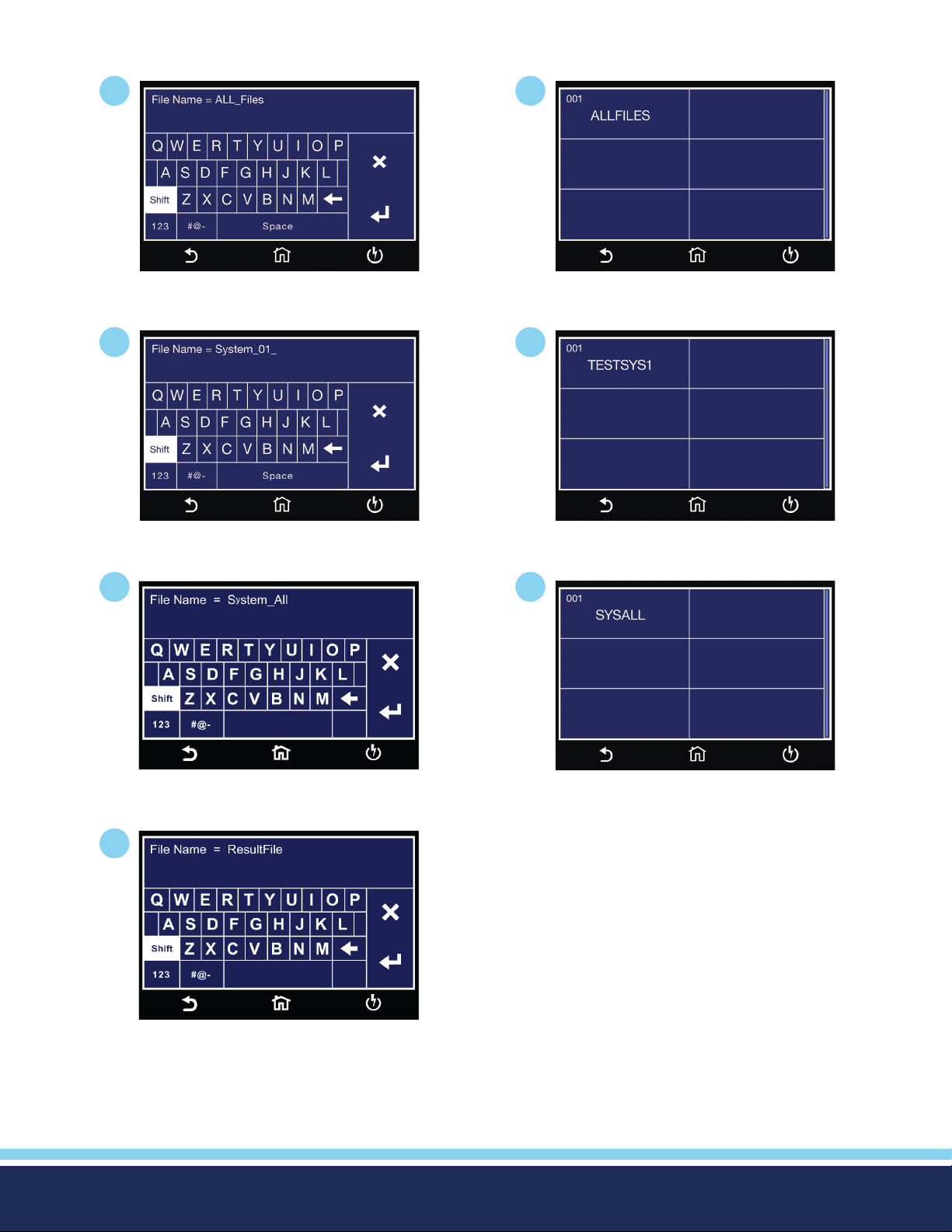
Import all Test les.Enter le name for exporting All Files.
6
Import System le.Enter le name for exporting System File.
7
Enter le name for exporting System
and All Files.
9
Enter le name for exporting results
from internal memory.
8
Import System and all Test les.
With Result Setup Location set to Int. Memory, Transfer can be used to export result data stored on the internal
memory. The number displayed shows total number of available results stored on internal memory.
© Ikonix USA 2021
24
Page 25
Hardware
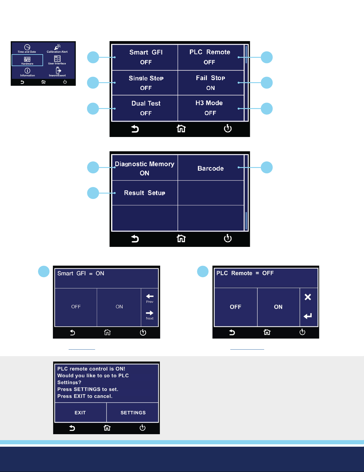
The Hardware menu allows the user to setup hardware parameters.
Setup System Menu
1
3
2
4
5 6
Hardware Menu
7
8
9
Hardware Menu Cont.
1
Enter SmartGFI value. Select PLC Remote ON or OFF.
This screen comes up when pressing TEST button while
PLC is ON warning customer to adjust PLC setting if need
to use the TEST button.
2
© Ikonix USA 2021
Continued on next page
25
C
Page 26
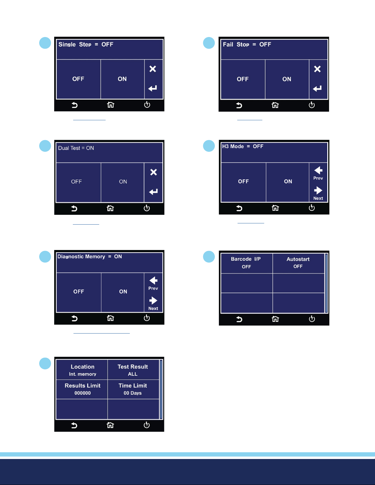
Hardware Continued
3
Select Single Step ON or OFF.
5
Select Dual Test ON or OFF for Dual
Remote Palm Switches.
4
Select Fail Stop ON or OFF.
6
Select H3 Mode ON or OFF. (Optional)
7
Select Diagnostic Memory ON or OFF.
9
8
Barcode Menu.
Results Setup Menu.
© Ikonix USA 2021
26
Page 27
Hardware Parameter Descriptions
Descriptions of Hardware parameters are listed in the following table:
System
Setting Description
Parameter
Smart GFI ON/
OFF
PLC Remote ON/
OFF
Single Step ON/
OFF
The high voltage power supply of the Hypot is internally referenced to earth ground. Since the leakage current
measuring circuit of the instrument monitors only current that ows through the return lead the possibility exists
for current to ow directly from the high voltage output to earth ground without being measured. The SmartGFI
(Ground Fault Interrupt) circuit monitors the current between the high voltage output and earth ground. Therefore, if you touch the high voltage lead and earth ground, the instrument will detect this hazardous condition and
shut off immediately.
SmartGFI goes beyond a standard GFI circuit by automatically determining the return conguration of the DUT
(grounded or oating) and enabling or disabling depending on the situation. When the Hypot’s Return lead is
oating, the SmartGFI circuit enables, protecting the test operator from electric shock. When the Hypot’s Return
lead is earth grounded, the SmartGFI circuit disables and the instrument operates in a grounded return mode of
operation. If the GFI were to remain active in this state, the instrument would continuously fail since all current
is returning through earth ground. By disabling the SmartGFI circuit and operating in a grounded return mode,
Hypot allows the user to perform tests on devices that have their chassis’s earth grounded by the test xture or
test environment.
Allows the user to initiate a test through the REMOTE INPUT on the rear panel of the instrument. If PLC Remote
= ON the front panel TEST button is disabled and a test may only be started through the rear panel Remote I/O.
If PLC Remote = OFF, the test must be initiated via the front panel TEST button.
Temporarily overrides the automatic connection feature. If Single Step = ON the instrument will pause after each
step is completed, even if step Connect function is set to ON. To continue the test sequence, press the TEST
button to execute the next connected step. Each time the TEST button is pressed the next connected step will
execute. If you press the RESET button before completing all connected steps, it will return the instrument to the
original starting step. If a step fails and you wish to continue to the next step, do not press the RESET button but
press the TEST button.
Fail Stop ON/
OFF
Dual Test ON/
OFF
H3 Mode ON/
OFF
Diagnostic
Memory
ON/
OFF
If Fail Stop = ON, a sequence of tests will stop if a failure occurs. If Fail Stop = OFF, the sequence of tests will
continue to the end of the sequence regardless of whether or not a failure has occurred. If a failure has occurred,
the red RESET button will light and alarm will sound indicating failure during the sequence. Pressing the RESET
button will silence the alarm and reset the instrument.
The Dual Remote Test Switch option allows you to congure dual palm switches for safe production line operation. Both PLC Remote and Dual Test must be ON in order for dual remote test switch operation below to work.
The rear panel remote interface is recongured to allow two test switches instead of the standard reset and test
inputs. The two test switches have to be pressed within 0.5 seconds to activate the test process. The two test
switches must remain closed to continue the test. If either of the test switches is released, the process will be
shut down immediately. The functions of the Test and Reset switches on the front panel will be disabled if the
dual test switches are enabled. When the Dual Test parameter is turned OFF, the Test and Reset switches on the
front and rear panel behave the same as the standard instrument, and are controlled by the PLC Remote On/Off
selection.
Optional - The mimic H3 command set option for Hypot allows to emulate the BUS remote commands that were
previously used on Hypot III instrument. The full list of commands can be found in Hypot III manual.
The Diagnostic Memory is a feature that keeps snap-shot records of the tests that the instrument performs. It
has a limited capacity to record basic information from test results (up to 4000 results), as well as a capacity to
keep running totals for the instrument; number of ACW/DCW/IR tests performed, number of ACW/DCW/IR tests
passed, total amount of time the instrument is outputting voltage, etc. These numbers are used by our marketing team to get a rudimentary idea of how our customers are using the instruments as well as help us troubleshoot any possible issues if the instrument comes back for repairs. This is a user-selectable feature and can be
enabled or disabled from the Hardware Menu of the instrument.
© Ikonix USA 2021
27
Page 28
The table below shows a full list of information that will be recorded if the Diagnostic Memory is enabled:
Information Recorded Description
Running Totals Total time duration the output is ON
Total time duration the instrument is ON
Total number (summation) of all tests performed
Total number of ACW tests performed
Total number of DCW tests performed
Total number of IR tests performed
Total number of ACW Pass
Total number of DCW Pass
Total number of IR Pass
Number of times FailChek is used
Test Results Number
Date
Time
Test Type (ACW/DCW/IR)
Status (PASS/FAIL/ABORT)
Voltage
Current/Resistance
I-max
Dwell Time
Frequency
Settings Color Style is selected
Home Screen conguration
Smart GFI (Yes/No)
PLC Remote (Yes/No)
Single Step (Yes/No)
Fail Stop: y/n
Remote Bus Active (Yes/No)
Continuity (Yes/No)
Prompt (Yes/No)
© Ikonix USA 2021
Arc Detect (Yes/No)
Charge-Lo (Yes/No)
Ramp-Hi (Yes/No)
Number of test les created/used
Language
28
Page 29

Hypot® comes from the factory with the following system presets:
System Parameters
Setup Sys. PLC Remote
Single Step
Fail Stop
Alarm
Results
Smart GFI
Results
Cal Alert
Security
OFF
OFF
ON
5
Last
ON
Last
ON
OFF
© Ikonix USA 2021
29
Page 30
Barcode
Barcode I/P
The Barcode function allows you to connect a barcode scanner directly to the front panel of the instrument’s barcode port. This is
utilized to enter product and serial number information for testing.
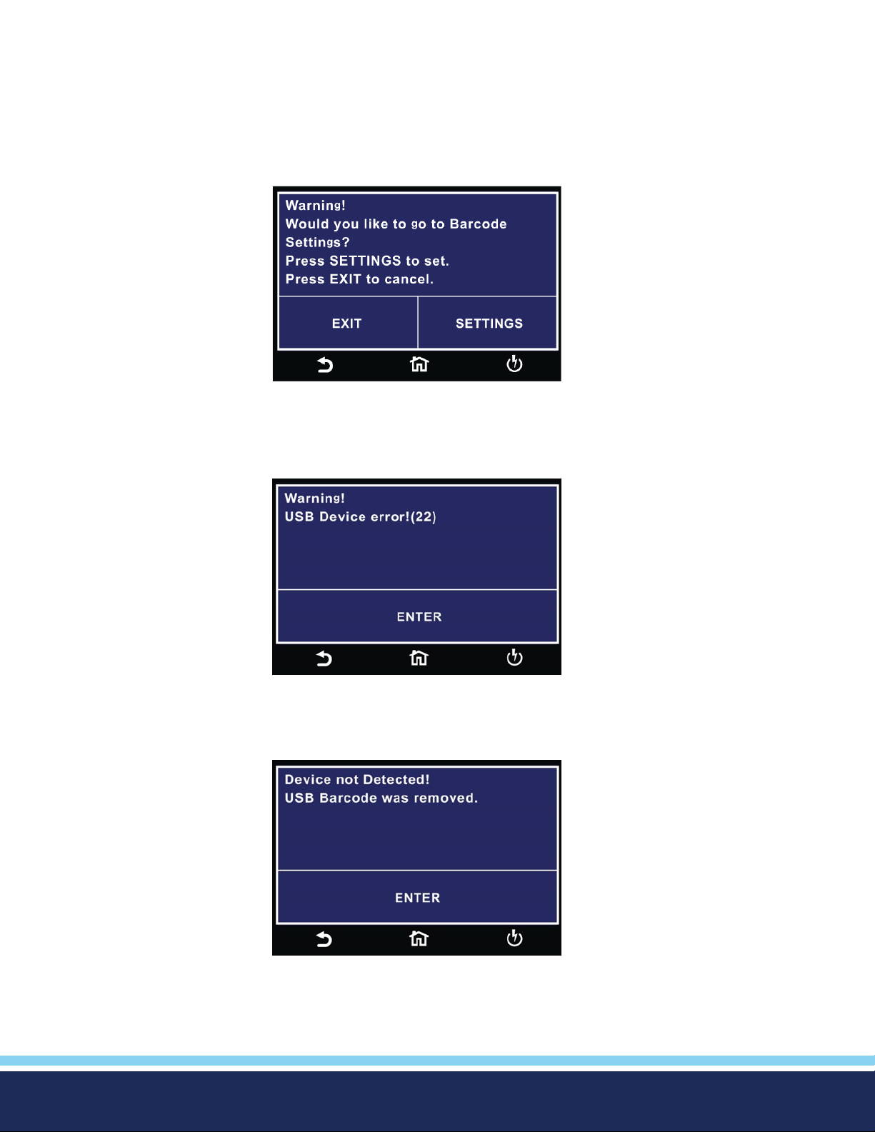
To use this function, plug a USB type barcode reader into the barcode port on the front panel of the instrument. Once a USB
barcode is plugged in, the instrument will notify you that a reader has been detected:
If there is a problem with the connection to the barcode reader or an incompatible device is plugged into the USB barcode port,
the following message will appear:
If the USB barcode device is removed while the instrument is powered on, the following message will appear:
© Ikonix USA 2021
30
Page 31

Important Information regarding the Barcode Feature
There are two options under Barcode, Barcode I/P and Autostart.
You can set the Barcode I/P function to OFF, SER/PROD, SERIAL #, PRODUCT # or RUN FILE.
When the setting is SERIAL#, PRODUCT# or SER/PROD you can scan barcodes in the Perform Tests screen before the test is
started.
Carriage Return (Enter) Function
The barcode scanner needs to be programmed to perform a carriage return function after each scan. A carriage return, also
known as the enter key, is used to bring the cursor down or onto the next data eld after each scan. Please refer to the barcode
manufactures’ programming instructions to add “Carriage Return/Enter” at the end of scan.
After the barcodes are scanned, pressing TEST will initiate the test sequence. Pressing RESET will abort the TEST sequence. The
barcode function allows for the re-scanning of barcodes if the previously scanned barcode was incorrect. Re-scanning is available
in the SERIAL#, PRODUCT# and SER/PROD modes. Any time before a test is initiated; you can re-scan a barcode. If you decide
to re-scan barcodes when the Barcode I/P setting is set to SER/PROD, the barcode function will rst replace the data in the Serial
Number eld, and if you re-scan another barcode, the barcode function will replace the data in the Product Number eld.
The RUN FILE selection gives you the ability to automatically load a test le based on what barcode is scanned from the Perform
Tests screen.
To completely enable this feature, you must name the desired test le for a particular product the exact alpha-numeric code that
is on the product’s barcode label. For example, if Product A has barcode “12345678”, then the test le that you would like to
run when testing Product A must be named “12345678”. Upon scanning the barcode, the Hypot will immediately load the test
associated with that barcode. The test le name is limited to 8 characters. However, if you name a test le with the maximum 8
characters, this function will still initiate a test when a product’s barcode begins with those rst 8 characters, even if the barcode
has more than 8 characters.
The Maximum Length of the Barcode Model/Serial Number is Limited to 21 Characters
When using certain features of barcoding, the instrument’s response to the TD? and RD x? commands will differ slightly to an
instrument that is not utilizing this function. For all types of tests (ACW, DCW, IR, CONT) two elds are added to the end of the
standard response when the Barcode I/P setting is set to SERIAL#, PRODUCT# or SER/PROD.
The rst eld contains the Serial Number information and the second eld includes the Product Number information. Both elds
are included regardless of which of these three modes are selected. The instrument will simply substitute a “0” for the eld if it
is not applicable to the setting. For example, if a user had their Barcode I/P setting set to SERIAL#, and scanned a Serial Number
with the value “12345678”, the TD? response for an ACW test could be:
01,ACW,Pass,1.24,1.0 00,0.900,1.0,12345678,0
Note that there is a “0” in the Product Number eld because the Barcode I/P setting is SERIAL#. When the Barcode I/P setting is
RUN FILE or OFF, these elds are not included in the TD? and RD x? responses.
© Ikonix USA 2021
31
Page 32
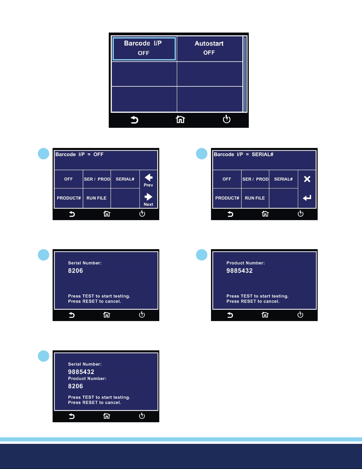
Barcode I/P
Barcode Menu
1
Select Barcode input option.
3
2
Select Barcode type.
4
Example SERIAL # screen.
5
Example SER/PROD screen.
© Ikonix USA 2021
Example PRODUCT # screen.
32
Page 33
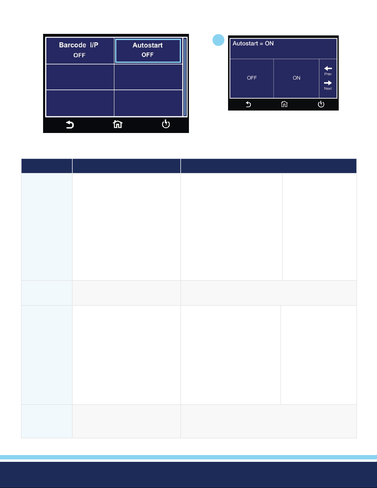
Barcode Autostart
Barcode Menu
Mode Description Auto Start On/OFF
1
Select Autostart ON or OFF.
Serial / Product If test lename (CASESENSTIVE)
matches the Product Name/Number,
the instrument will Auto Load that
test le. Test results will store both
product and serial number.
Serial #
Product # If test lename (CASESENSTIVE)
Records the serial number for the
currently loaded test le.
matches the Product Name/Number,
the instrument will Auto Load that
test le. Test results will store both
product and serial number.
ON – Enables the test to be auto
started on the second scan of the
matching product number. Serial
and Product numbers are recorded
and included in the results data.
Example Steps:
• Scan Serial Number
• Scan Product Number
• Scan same Product Number
again to start the test.
N/A
ON – Enables the test to be auto
started on the second scan of
the matching product number.
Product number is recorded and
included in the results data.
OFF – Manually press
TEST button to start
test.
OFF – Manually press
TEST button to start test.
Run File Finds the test le name same as the
scanned barcode and loads this test.
The test will also auto start once the
test is loaded.
© Ikonix USA 2021
Example Steps:
• Scan Product Number or Name
• Scan same Product Number or
Name again to start the test
N/A
33
Page 34
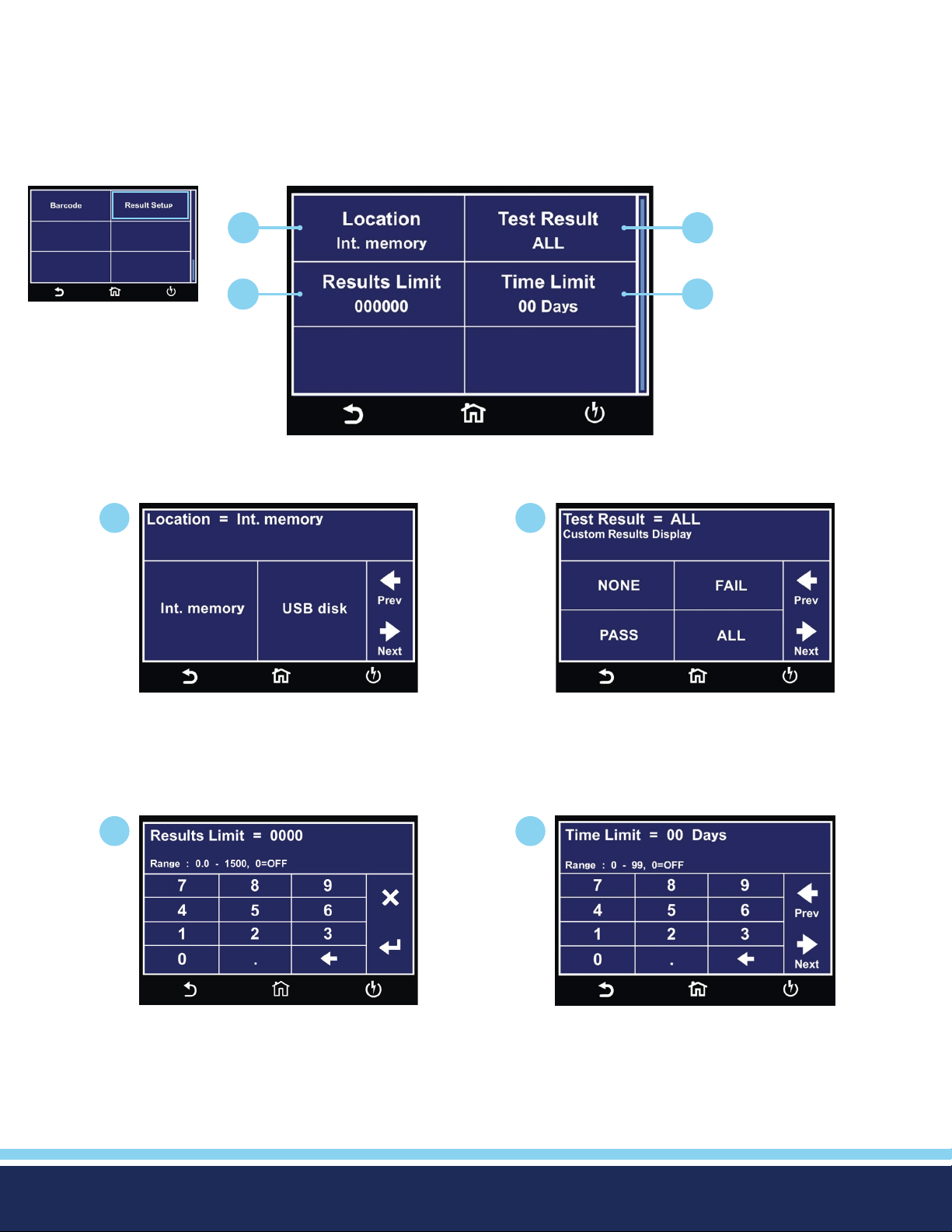
Results Setup
Select Int. memory if you wish to store the test results on the onboard instrument memory. Select USB disk if you wish to save the
test results on an external USB ash drive. For best results use the USB ash drive provided by Associated Research.
Select PASS to save the results of the steps that passed. Select FAIL to save the results of the steps that failed. Select ALL to save
all the test results. Selecting NONE will not save any results to the internal memory.
Hardware Menu
1
1
2
3 4
Result Setup Menu
2
Select Location for Result Data.
3
Enter Results Limit.
You can set the Results Limit. Select from 0 up to 1500 with 0 being OFF. Selecting 0 will set the Results limit to OFF which means
you can store as many results as desired until you reach the maximum capability of 1500 results.
Select type of Test Results to be saved.
4
Enter Time Limit.
© Ikonix USA 2021
34
Page 35
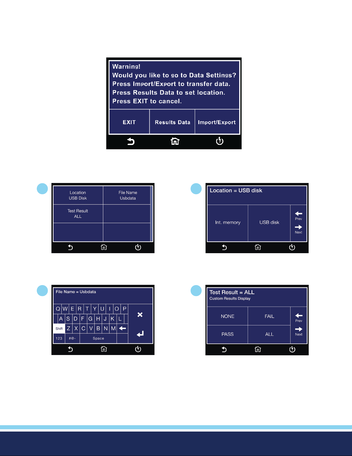
Internal Memory
Insert USB disk into Data port and the following screen will appear. Select Result Data to go to Result Data settings menu. Select
Import/Export to use the Import/Export menu to transfer data. Please refer to the Import/Export section of this manual.
1
Result Setup USB DISK Menu.
3
2
Select Location for Result Data.
4
Enter File Name.
© Ikonix USA 2021
Select type of Test Results to be saved.
35
Page 36
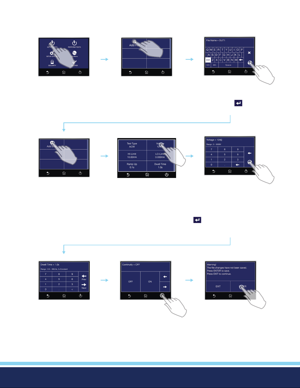
2. Setup Tests
The following sequence describes the steps necessary to create a test le, program the test parameters and save the test le:
TAP SETUP TESTS
Home Screen
TAP ADD STEP
Add Step
TAP ADD FILE
File Screen
TAP TEST SETTING
Tap the test parameter you
would like to edit. Swipe up
and down to scroll through test
parameters.
ADD FILE NAME
(MAXIMUM 8 CHARACTERS)
Tap the ENTER ( ) key to
save your selection
EDIT
PARAMETERS
Tap parameter values to edit
individually. After you adjust
each parameter, tap ENTER
( ) arrow key to save changes.
PARAMETERS
Scroll through each parameter
to adjust values based on your
© Ikonix USA 2021
ADJUST
application.
EXIT
PARAMETERS
Press the Test Screen button to
exit out of Parameters.
SAVE FILE
CHANGES
Press ENTER to save your le
changes. You will be redirected
to the Test Screen.
36
Page 37
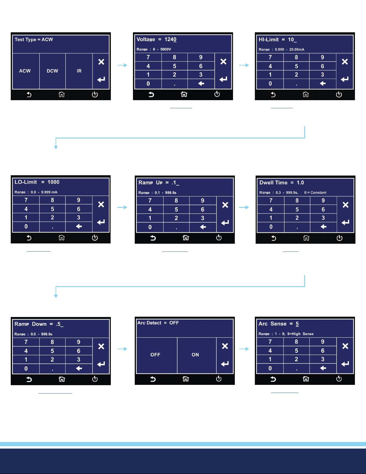
2.1 Setup AC Withstand Test
Select ACW Test type.
Enter LO-Limit Total.
Enter AC test Voltage.
Enter test Ramp Up time.
Enter HI-Limit Total.
Enter test Dwell time.
Enter test Ramp Down time.
© Ikonix USA 2021
Select Arc Detect ON or OFF. Enter Arc Sense value.
Continued on next page
37
C
Page 38
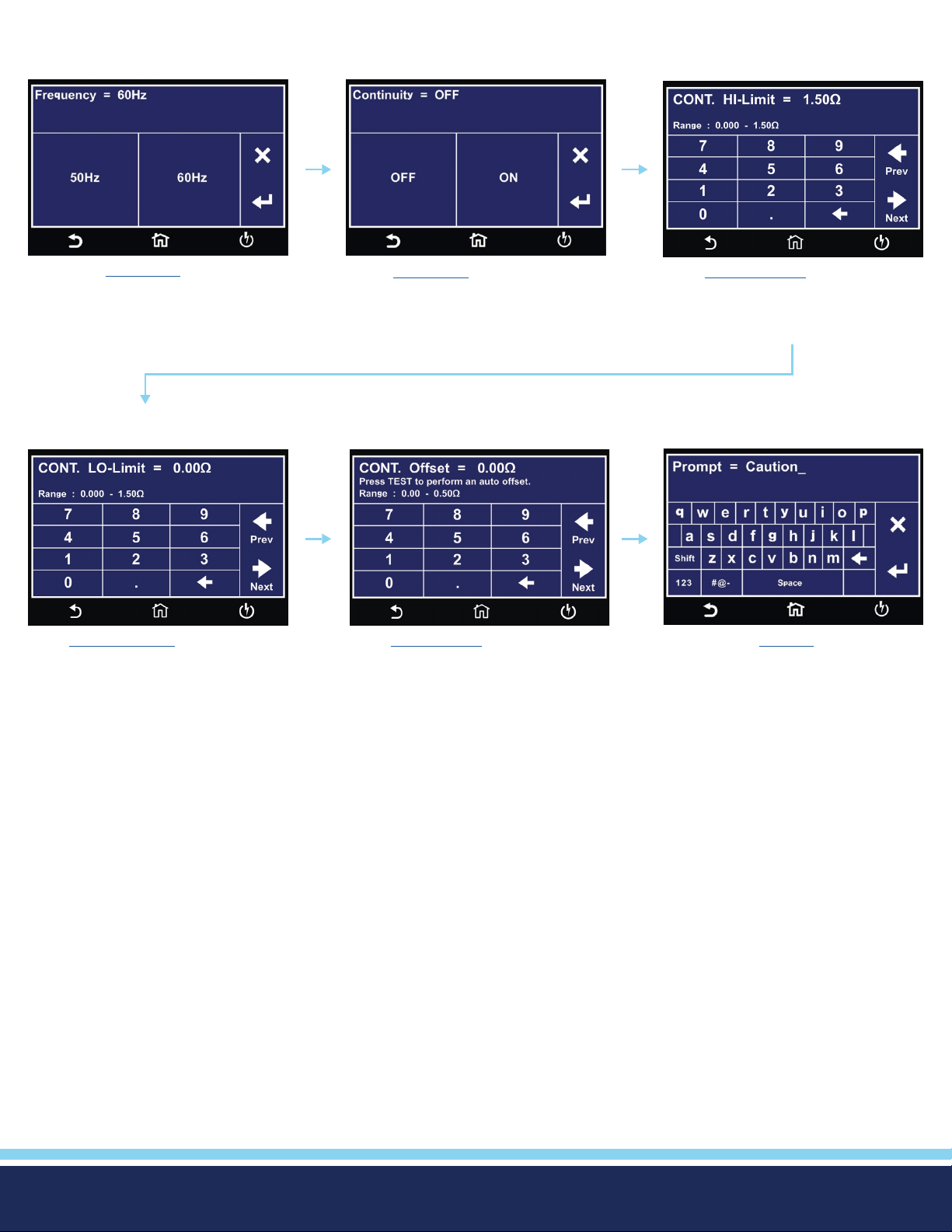
Setup AC Withstand Test Continued
Select test Frequency.
Enter Cont. LO-Limit value.
Select Continuity ON or OFF.
Enter Cont. Offset value.
Enter Cont. HI-Limit value
Enter text for Prompt.
© Ikonix USA 2021
38
Page 39
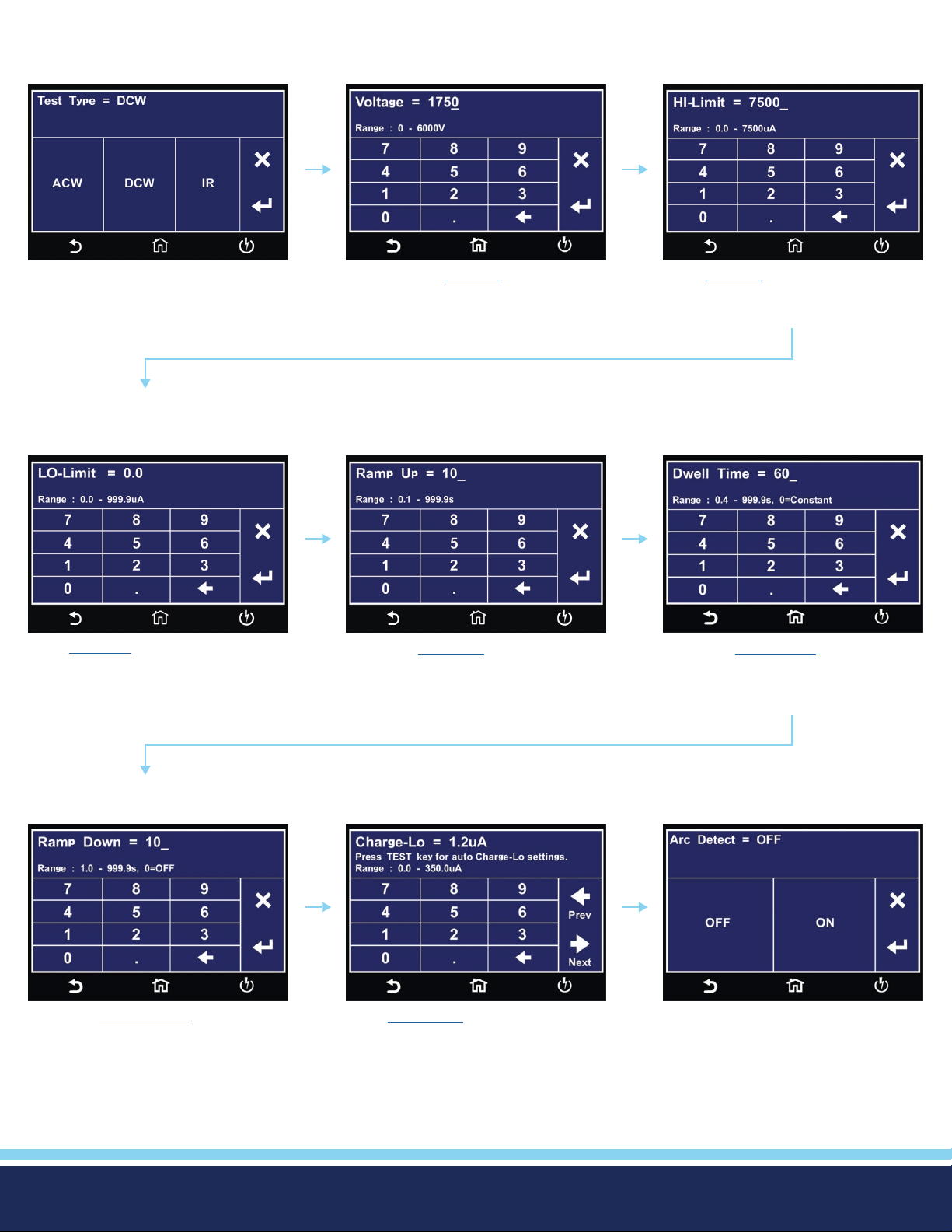
2.2 Setup DC Withstand Test
Select DCW Test type.
Enter LO-Limit.
Enter DC test Voltage.
Enter test Ramp Up time.
Enter HI-Limit.
Enter test Dwell Time time.
Enter test Ramp Down time.
© Ikonix USA 2021
Enter Charge-Lo value to manually
set Charge-Lo or Press TEST to perform auto Charge-Lo.
Select Arc Detect ON or OFF.
Continued on next page
39
C
Page 40
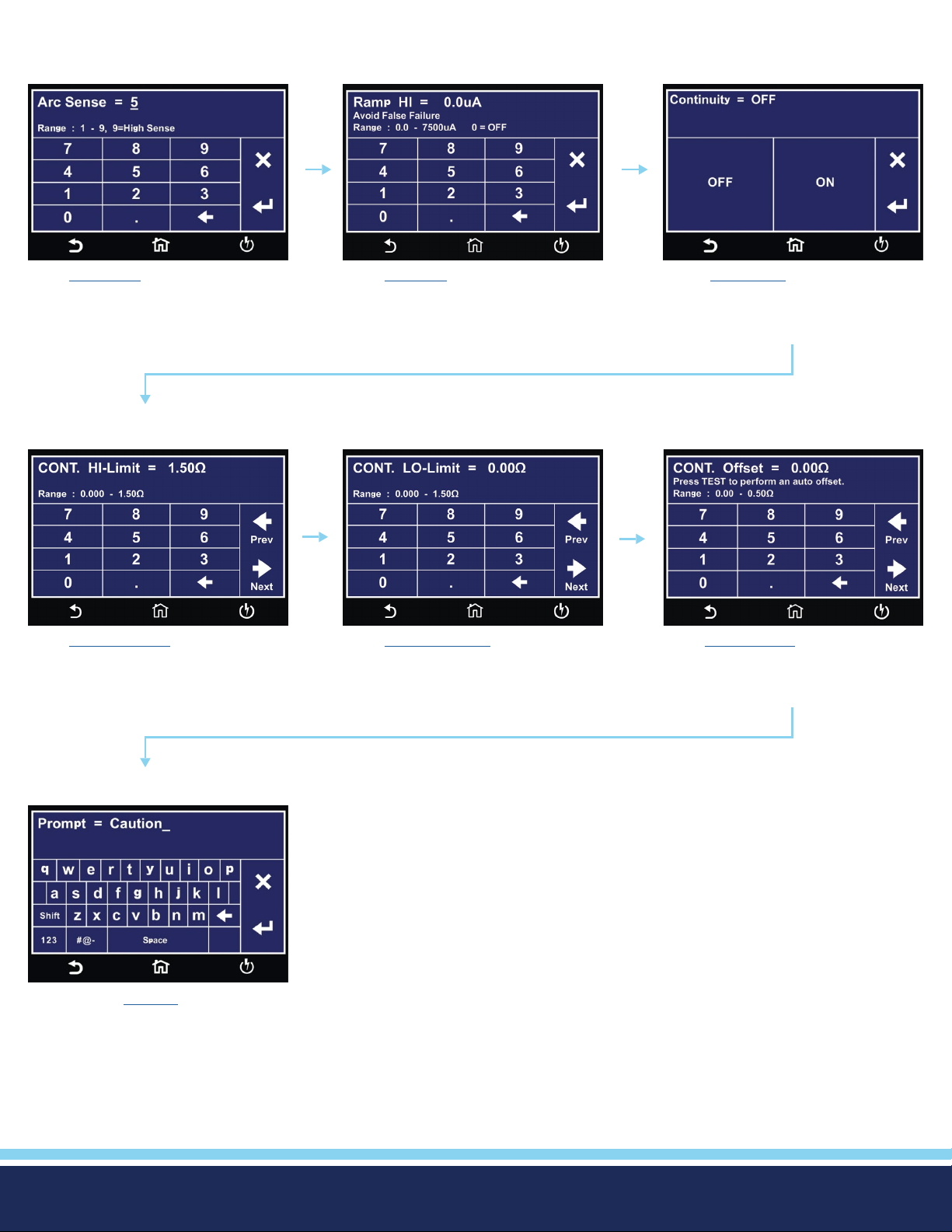
Setup DC Withstand Test Continued
Enter Arc Sense value.
Enter Ramp-HI value.
Select Continuity ON or OFF.
Enter Cont. Offset value.Enter Cont. HI-Limit value. Enter Cont. LO-Limit value.
Enter text for Prompt.
© Ikonix USA 2021
40
Page 41
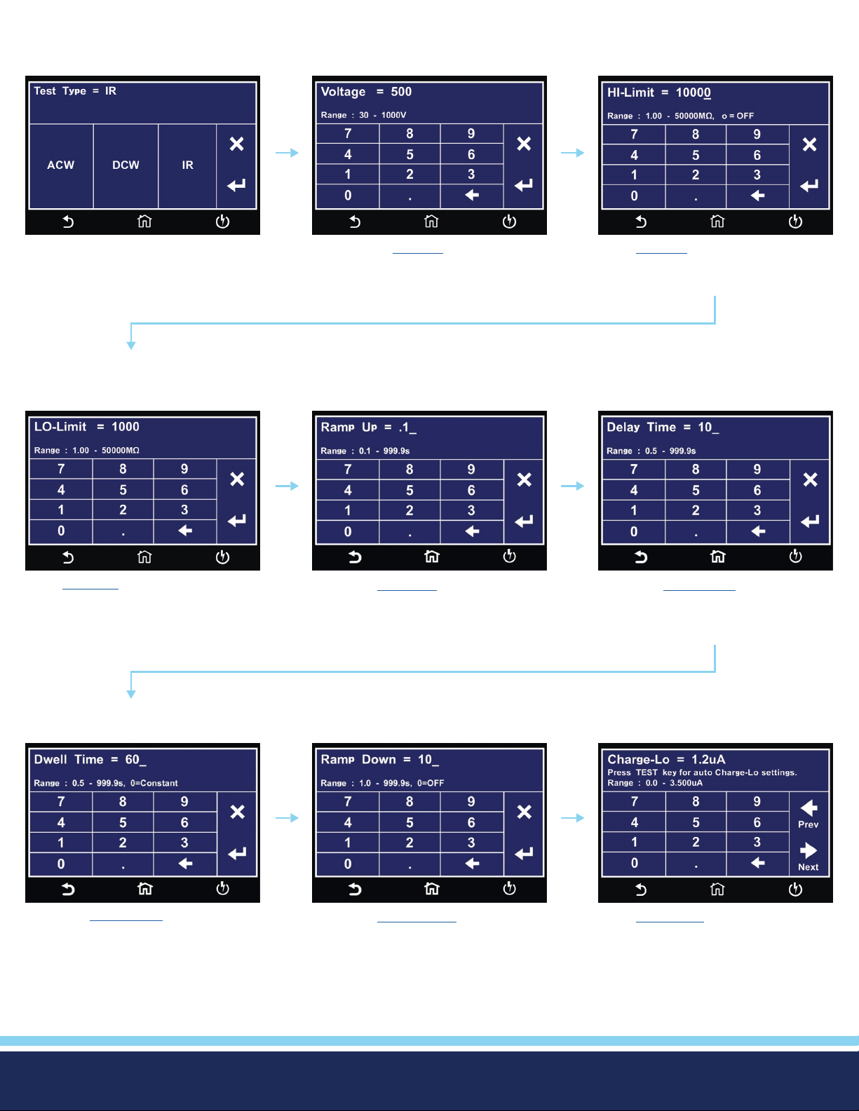
2.3 Setup Insulation Resistance Test
Select IR Test type.
Enter LO-Limit.
Enter IR test Voltage.
Enter test Ramp Up time.
Enter HI-Limit.
Enter test Delay Time.
Enter test Dwell Time.
© Ikonix USA 2021
Enter test Ramp Down time.
Enter Charge-Lo value to manually
set Charge-Lo or Press TEST to
perform auto Charge-Lo.
Continued on next page
41
C
Page 42
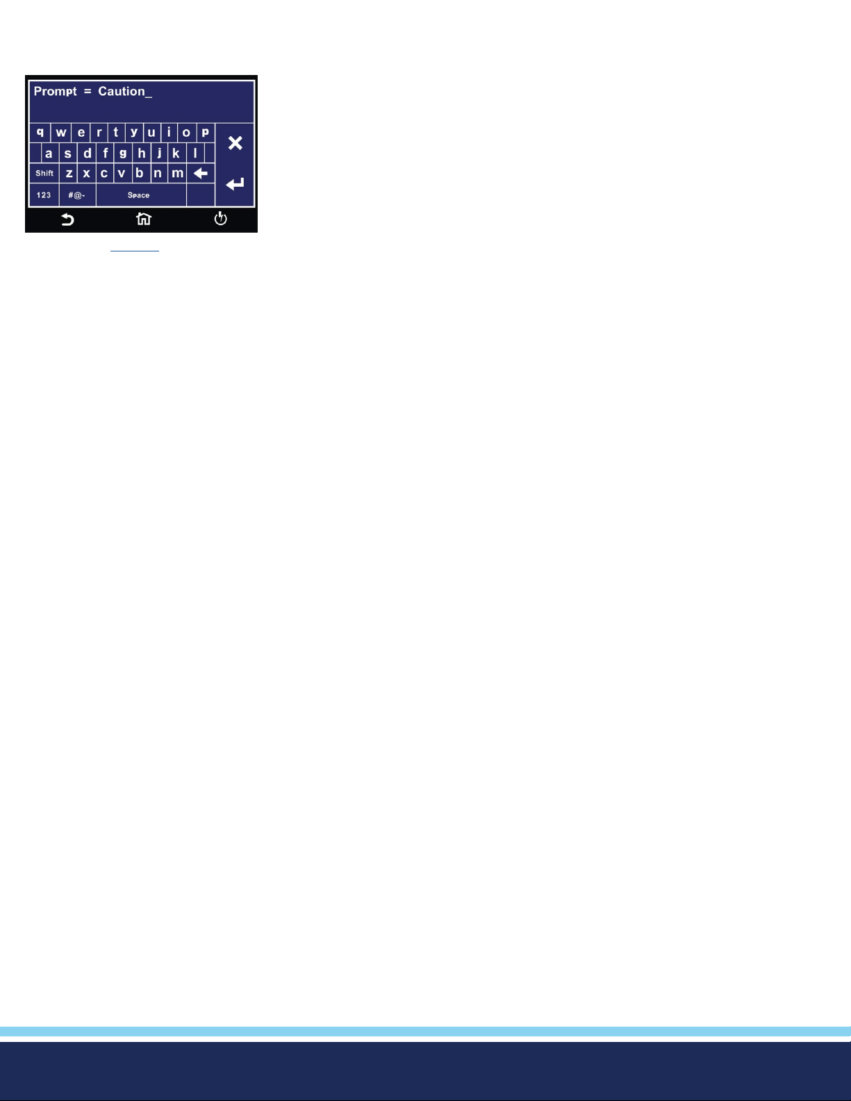
Setup Insulation Resistance Test Continued
Enter text for Prompt.
© Ikonix USA 2021
42
Page 43
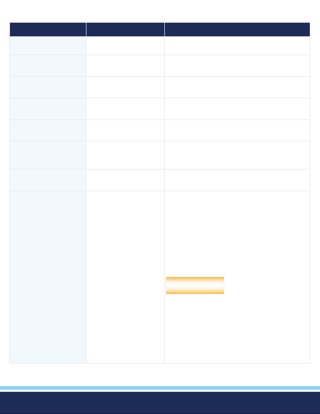
Test Parameters Description
Test Parameter Test Typ e Description
Voltage ACW, DCW, IR The voltage that is applied to the high voltage and return
terminals during a test.
HI-Limit ACW, DCW, IR The maximum current or resistance threshold that triggers
a failure when exceeded.
LO-Limit ACW, DCW, IR The minimum current or resistance threshold that triggers
a failure when not exceeded.
Ramp Up ACW, DCW, IR The length of time that is allowed for the test voltage to
climb from 0 to the programmed test voltage.
Dwell Time ACW, DCW, IR The length of time that is allowed for the programmed test
voltage to be applied.
Delay IR The length of time that the programmed test voltage is
applied but no judgment of the set parameters is made.
Judgment of the parameters is not made until the end of
the delay time.
Ramp Down ACW, DCW, IR The length of time that is allowed for the test voltage to
decay from programmed test voltage to 0.
Charge-LO DCW, IR Use the Charge-LO function to check if the cables are con-
nected properly at the beginning of a test. A capacitive DUT
will draw charging current on the DC Withstand test when
the Output is activated. If the charging current is lower than
the setting, the test cables may not be connected properly.
The instrument can set the Charge-LO parameter manually
or automatically. To manually set the Charge-LO current, use
the touchscreen keypad to enter the value. To automatically
set the Charge-LO current select the Charge-LO parameter
and connect all test leads to the DUT as you would when
performing an actual DCW test. Press the TEST button on
the front panel of the instrument.
Please be aware that the program
CAUTION
S’il vous plaît soyez conscient que le programme va activer
haute tension sur le connecteur de sortie tandis que le bouton TEST est pressé
will activate high voltage on the
output connector while the TEST
button is pressed.
© Ikonix USA 2021
The program will read the charging current of the DUT and
set the Charge-LO current at approximately one half (1/2) of
the reading. The instrument will beep and the new value will
automatically be updated in the eld. You do not need to
select the ENTER key for the new parameter to be accepted.
Continued on next page
43
C
Page 44
Test Parameters Description Continued
Test Parameter Test Typ e Description
Ramp-HI DCW The Ramp-HI function is active during the Ramp period only.
Ramp-HI will allow current higher than the normal HI-Limit
current setting of the DC Withstand Voltage test to avoid
false failure due to charging current.
Arc Sense ACW, DCW The maximum allowable threshold for arcing. The numbers
1 through 9 correspond to the different arc sensitivity levels,
1 meaning the maximum threshold of allowable arcing and
9 meaning the minimum threshold of allowable arcing. Arc
detection is not required for testing.
Frequency ACW The frequency of the applied voltage or current. Select
between 50 and 60 Hz.
Offset Continuity Used to factor out resistance due to test leads or test
xture. Set manual or measure automatically.
To automatically set an Offset value, set the output voltage,
current, and frequency to the values you will use on the DUT
and connect the test cables, test xture, or with xturing
to the instrument. Next, for the Continuity test, short the
ends of the test cables and press the TEST button. The
instrument will beep and automatically update the new value
in the eld. You do not need to select the ENTER key for the
new parameter to be accepted.
Please be aware that the program
CAUTION
will activate high voltage on the
output connector while the TEST
button is pressed.
Note: Do not connect the DUT to the instrument when
performing an offset. This will create erroneous results when
you perform a test.
Prompt All The Prompt function allows you to insert a short line of text
in a step. The Prompt will appear on the screen before the
step is initiated and remains on the screen until you press
the TEST button. After you press the TEST button, the
Prompt will clear and the step will initialize.
© Ikonix USA 2021
44
Page 45
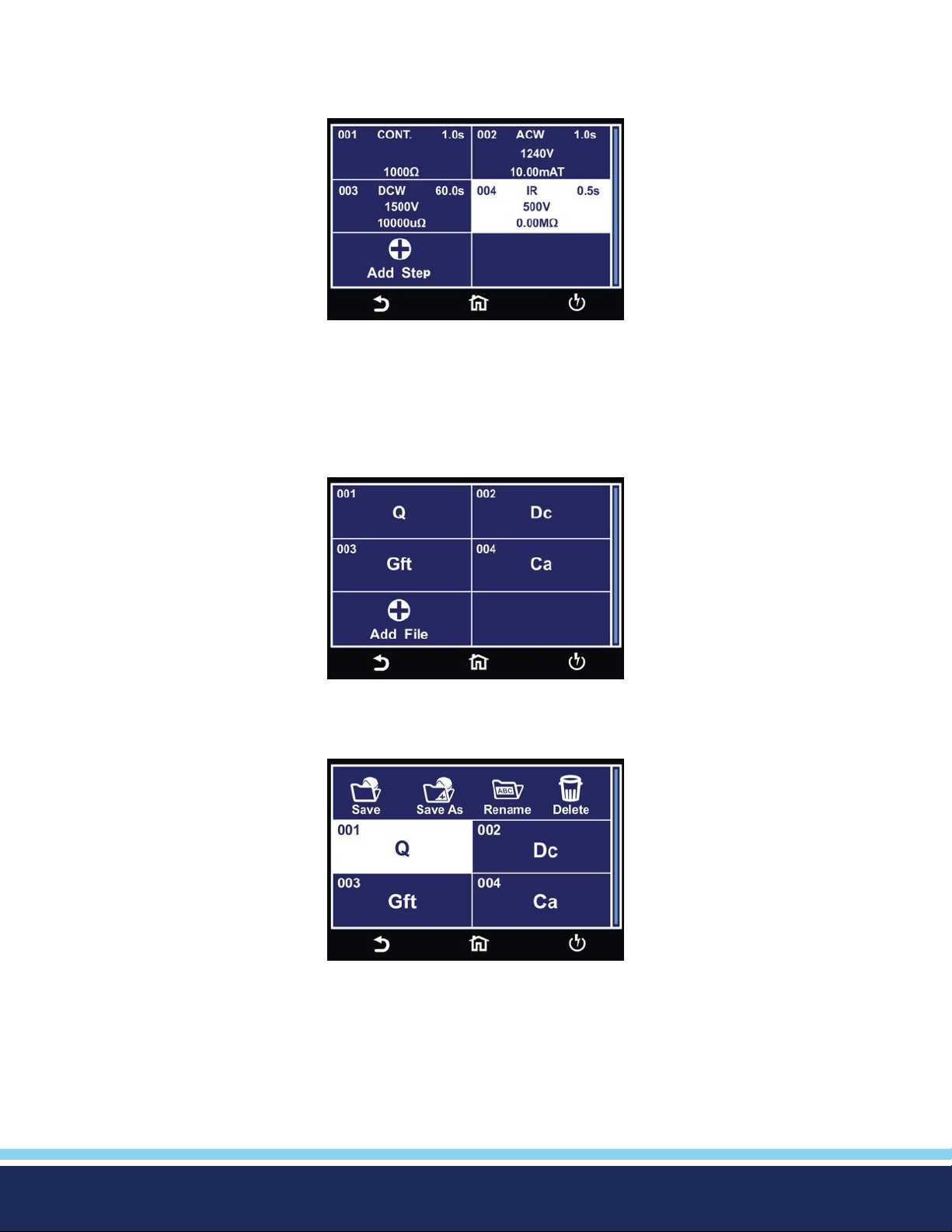
View Test Files
Once you have programmed and saved all tests, navigate to the Main Menu. Select the Setup Tests icon and select the test le
that you previously created. The screen should display all tests that you have programmed in this test le. For example:
Edit Test Files
Once you have programmed and saved all test les you can edit these les from the Setup Test menu. From the main menu
select Setup Test. The next screen will display all the test les that are stored on the instrument memory.
To edit test les touch and hold the screen on a test le name and the screen should change to the following:
© Ikonix USA 2021
45
Page 46
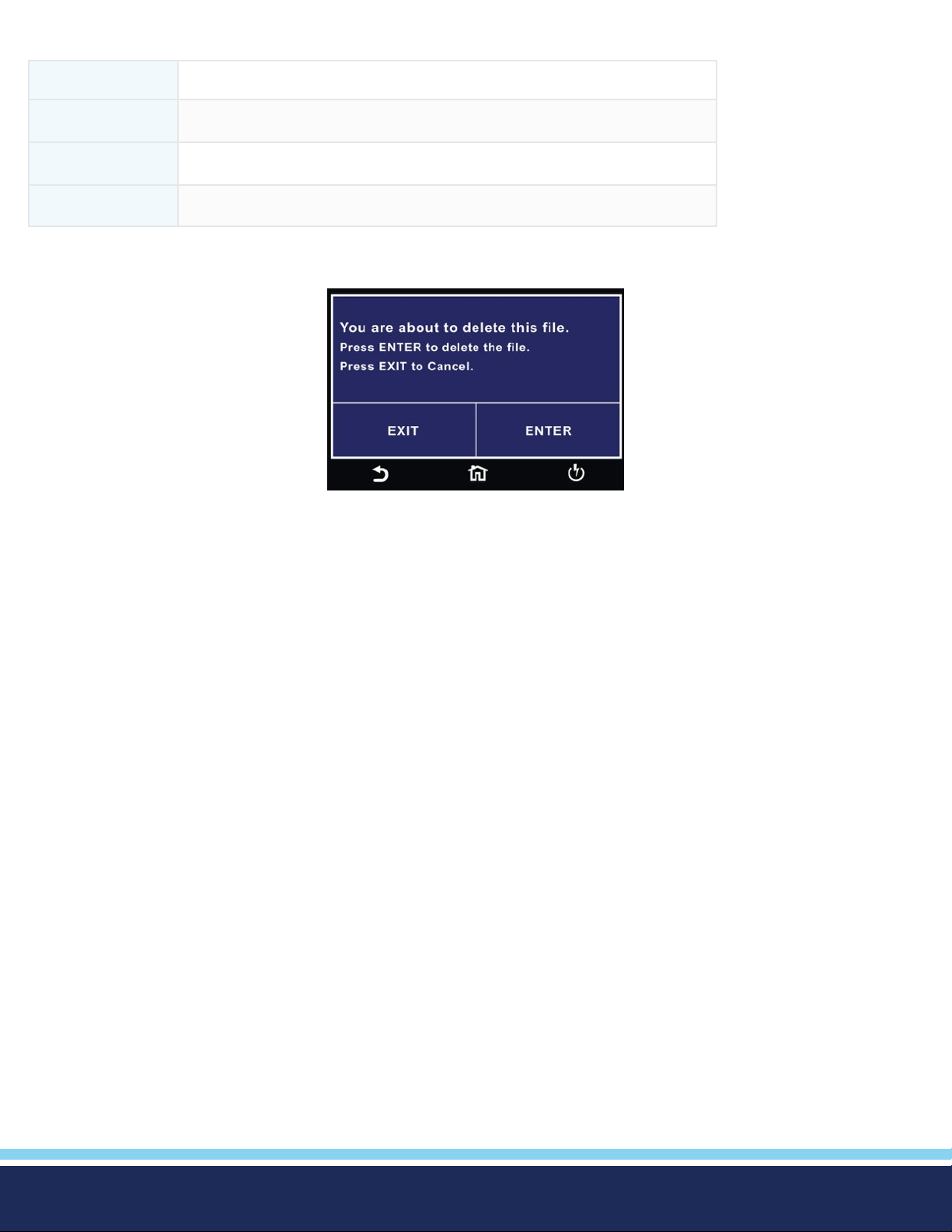
Select the test le and choose the operation you wish to perform from the following:
Save Make changes to an existing test le and save the changes
Save As Edit an existing test le and save the test le with a different name
Rename Rename an existing test le
Delete Delete an existing test le
If you choose to delete an existing test le a conrmation screen will appear as follows:
Select Exit to cancel deleting the test le or Enter to conrm the action.
© Ikonix USA 2021
46
Page 47
3. Perform Tests
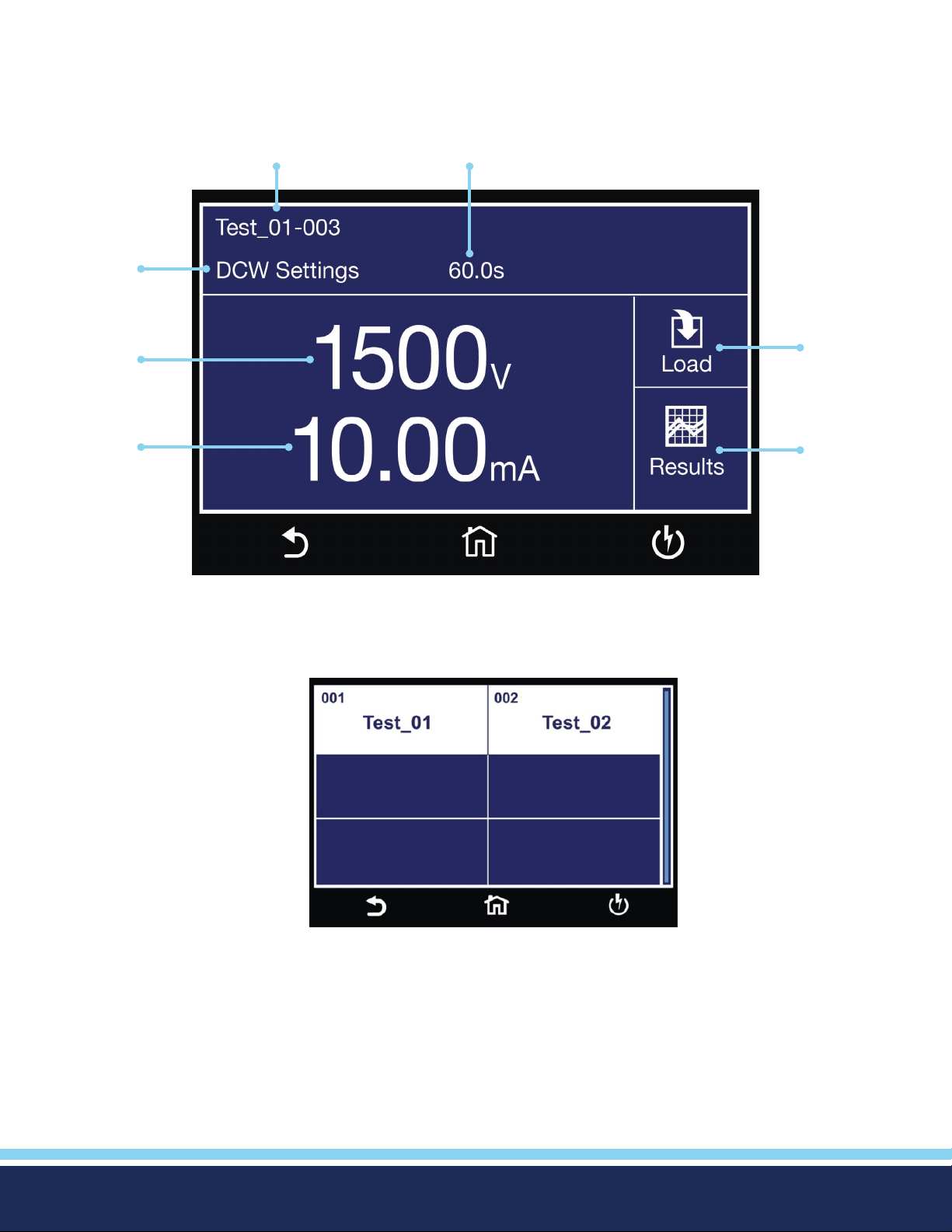
From the main menu select the Perform Test icon and the Perform Test screen will appear.
File Name and
Step Number Test Ti me
Test Typ e
Voltage or
Current
Setting
Current or
Resistance
Limit
Perform Tests Screen
Load
Different
File
View
Results
© Ikonix USA 2021
Load Test screen, if there are multiple test les saved
in the instrument select the Load icon and all the
test les will be displayed. You can select the test le
and the rst test step in the selected test le will be
displayed.
47
Page 48
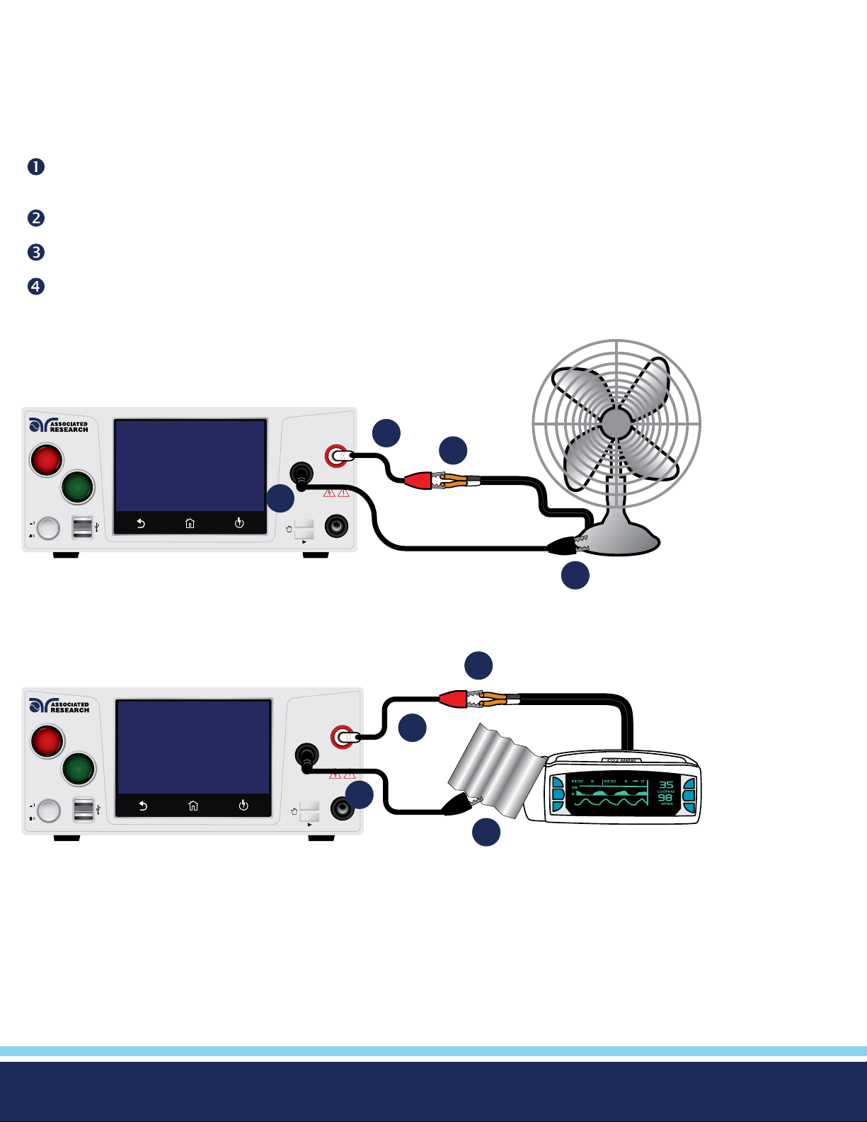
Instrument Connections
You may connect the test leads and the adaptor box to the receptacles located on the front or back of Hypot. These receptacles
are wired in parallel and you can use either depending upon the application.
Test Lead Connections
Connect the clip end of the return lead (P/N 2100A-13) to the exposed or dead metal on the chassis on the DUT. Always
connect the ground return clip rst and double check that it has a solid connection to the DUT.
Connect the black ground return lead (P/N 2100A-13) to the Return terminal located on the front panel of the instrument.
Connect the white high voltage lead (P/N 4040A-08) to the High Voltage terminal.
Connect the red clip end of the high voltage lead to the current carrying conductors of the DUT’s circuitry.
Exposed Metal Chassis Setup
Hypot® Series
RESET
TEST
POWER DATA
DIELECTRIC WITHSTAND TESTER
HIGH VOLTAGE
RETURN
2
My Menu / Select
CAUTION
HIGH VOLTAGE
5KVAC MAX.
6KVDC MAX.
CONT.
CHECK
3
4
BARCODE
1
Non Exposed Metal Chassis Setup
4
Hypot® Series
RESET
TEST
POWER D ATA
BARCODE
DIELECTRIC WITHSTAND TESTER
HIGH VOLTAGE
RETURN
CAUTION
HIGH VOLTAGE
5KVAC MAX.
6KVDC MAX.
CONT.
My Menu / Select
CHECK
3
FOIL
2
1
If there is no ground circuit present on the DUT, you can use test leads to connect the Hypot® to the DUT.
Did you know? If necessary, a 10 x 20 cm piece of foil can be attached to the enclosure to simulate a full hand contact to the
DUT. This foil acts as the return point. The return and sense (-) terminal are attached to the foil. Always check to make sure you
made a good connection between the DUT and the return clip.
© Ikonix USA 2021
48
Page 49
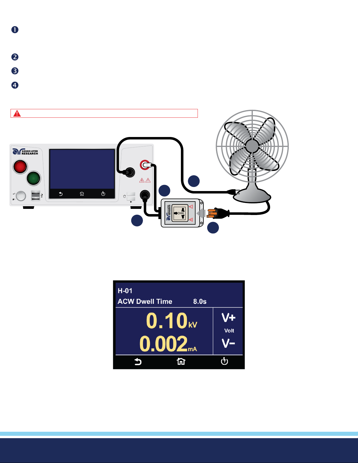
Adapter Box Connections
Connect the black ground return lead (P/N 2100A-13) to the front panel Return terminal and connect the other end of the
lead to the dead metal on the chassis of the DUT. Check to ensure a solid connection is made between the DUT and the
return clip.
Plug the black lead from the adapter box (P/N 365440) into the CONT. CHECK terminal located on the front panel.
Plug the white lead from the adapter box into the High Voltage terminal located on the front panel.
Plug the line cord of the DUT into the adapter box receptacle.
WARNING: DO NOT TOUCH THE DEVICE UNDER TEST ONCE YOU START THE TEST.
Hypot® Series
RESET
TEST
POWER DATA
BARCODE
DIELECTRIC WITHSTAND TESTER
HIGH VOLTAGE
RETURN
CAUTION
HIGH VOLTAGE
5KVAC MAX.
6KVDC MAX.
CONT.
My Menu / Select
CHECK
1
3
NL
5KVAC MAX.
6KVDC MAX.
HIGH VOLTAGE
CAUTION
2
4
Manual Voltage Adjustment
When Hypot is performing a test, “+” and “-” icons will appear on touch screen. These icons may be used to adjust the output
voltage while performing a test.
Pressing the “+” icon will increase the output voltage and pressing the “-” icon will decrease the output voltage. Manual voltage
adjustment temporarily overrides the voltage setting and only remains in effect until the test is terminated by Pass, Fail, or
Abort conditions. When Security feature is ON, manual voltage adjustment is disabled for users with limited access. You will not
see the “+” and “-” soft key selections in this case.
© Ikonix USA 2021
49
Page 50
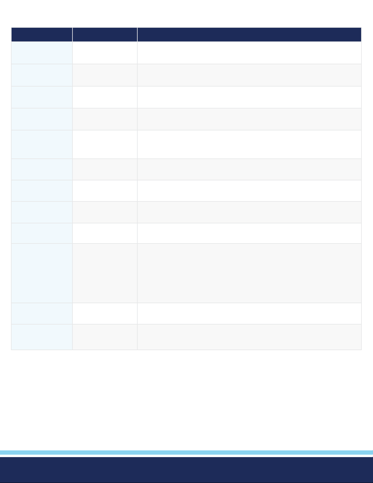
Failure Modes
Failure Message Test Typ e Description
Abort All This message appears on the display if you abort the test in process with the
RESET button or remote Reset control.
HI-Limit ACW, DCW, IR This message appears on the display if the DUT measurement exceeds the
HI-Limit setting of any parameter.
LO-Limit ACW, DCW, IR This message appears on the display if the DUT measurement drops below the
LO-Limit.
CONT. HI-Limit ACW, DCW This message appears on the display if the DUT fails the basic continuity check
performed during an AC/DC Withstand test (if Continuity is selected “ON”).
Arc-Fail ACW, DCW This message appears on the display if the DUT arcing current exceeds the Arc
Sense limit and Arc function is active (Arc Sense = 1…9) of the AC/DC Withstand
test.
Short ACW, DCW, IR This message appears on the display if the DUT current is well beyond the
metering range of the test.
Charge-LO DCW, IR This message appears on the display if the leakage current during Ramp-up falls
below the Charge -LO setting.
Breakdown ACW, DCW This message appears on the display if the DUT current is well beyond the
metering range of the test and the arcing condition beyond the arc sense limit.
GND-FLT ACW, DCW This message appears on the display if the GFI threshold is exceeded during the
test.
Interlock Open All This message appears on the display if the Remote Interlock feature is activated
before or during a test. The Remote Interlock feature utilizes a set of closed
contacts which will disable the instrument’s output if they are opened before
or during a test. You can also refer to the Remote Interlock as a remote system
lockout, utilizing “fail when open” logic. You can disable the Remote Interlock
feature by plugging the “Interlock Disable Key” provided into the Signal Input
connector
Ramp-Hi DCW This message appears on the display when the Ramp-Hi limit is exceeded during
the test.
OTP-Fail This message appears on the display if the Power Amplier has overheated. This
is an abnormal condition; please call to the factory for assistance.
© Ikonix USA 2021
50
Page 51
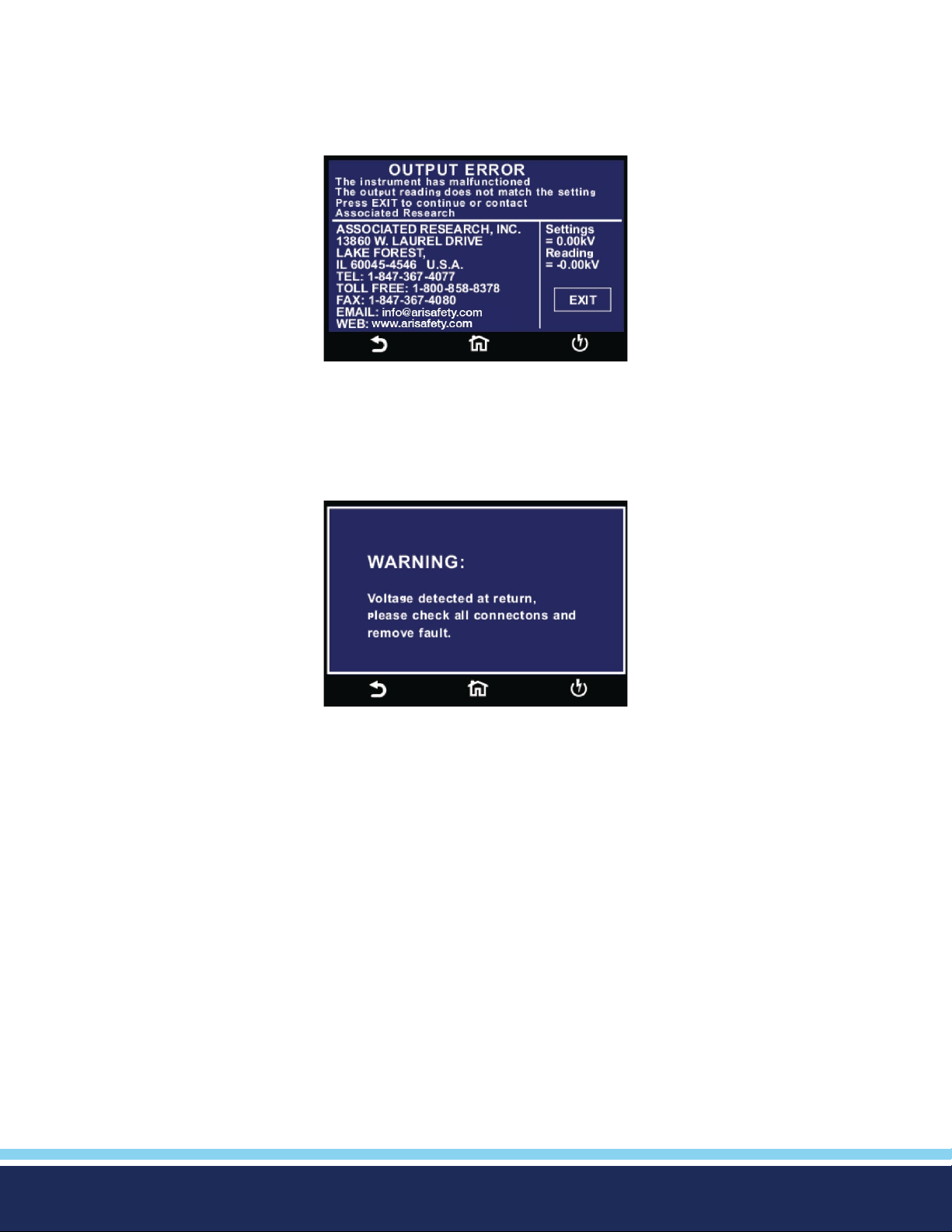
Error Messages
Output Error: This message appears on the display, if the instruments output reading does not match the setting. You will only
see this message if you press the EXIT key at the Output Error screen. If the instrument has an output problem when the TEST
button is pressed, the Output Error screen will appear as in image below. Bus will return "OUT-ERROR" if instrument is queried in
this state.
The RESET button is not active in this situation. Only the EXIT key will allow you to return to the Perform Test screen.
Voltage at Return: The Hypot contains a protective circuit on the Return. This circuit has the capability to protect the instrument
from getting damaged as result of line voltage coming back into the Return circuit. If the instrument detects any line voltage on
the Return circuit then the following screen will appear:
You can then check for any inappropriate connections.
© Ikonix USA 2021
51
Page 52
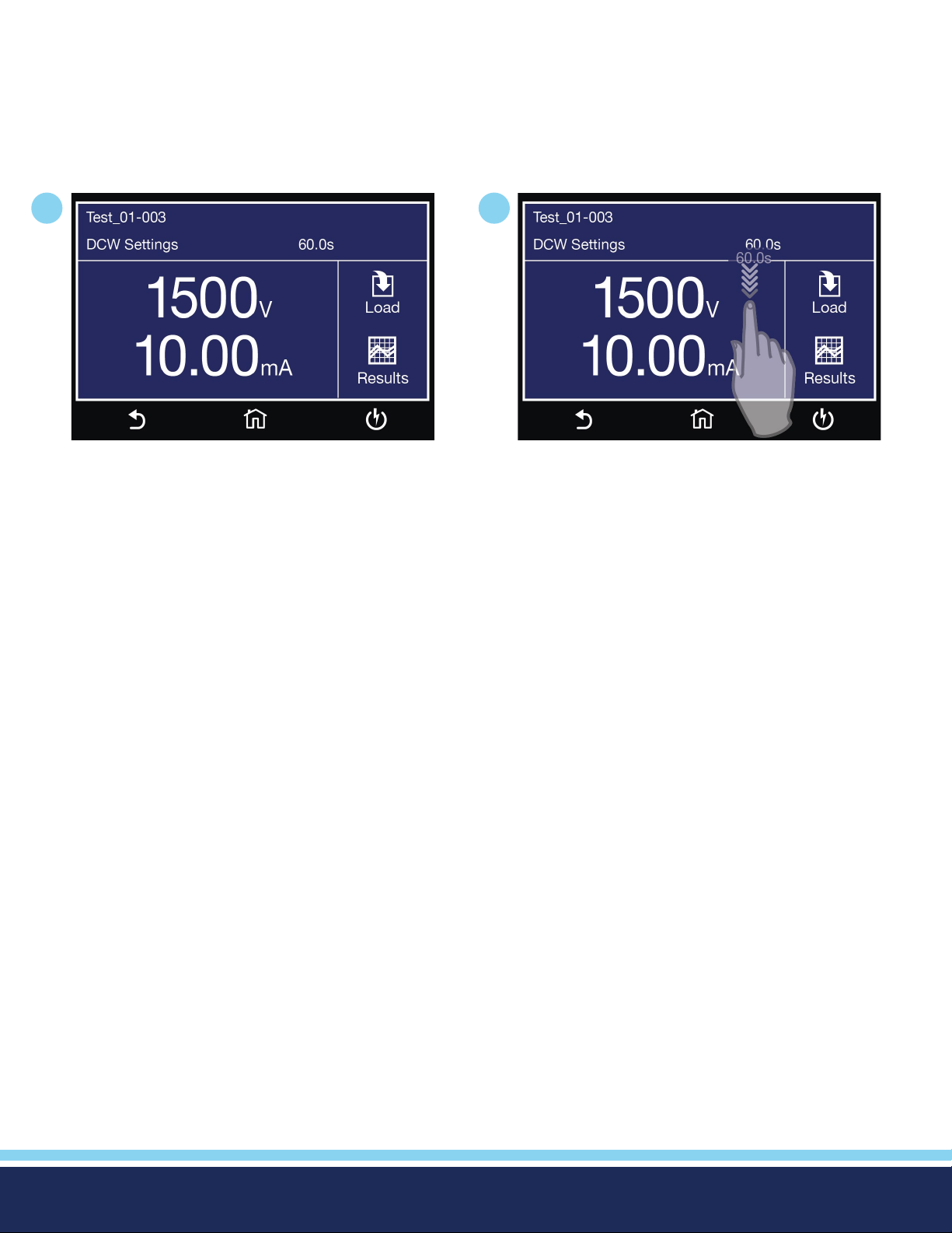
Meters
The Perform Test screen of the Hypot has several different meters depending on the type of test you are performing. You can
arrange these meters as desired. You can also tie these meters to the user security setup. The drag and drop feature of the
instrument allows you to set large and small meters. For example the following screen shot shows the Perform Test screen of the
DCW test:
1
In the image above, the two large meters display the
DCW test voltage and the Dwell Time.
2
Touch and hold the display on any of the meters and
drag it on to the location of a different meter and
the two meters will be swapped.
© Ikonix USA 2021
52
Page 53
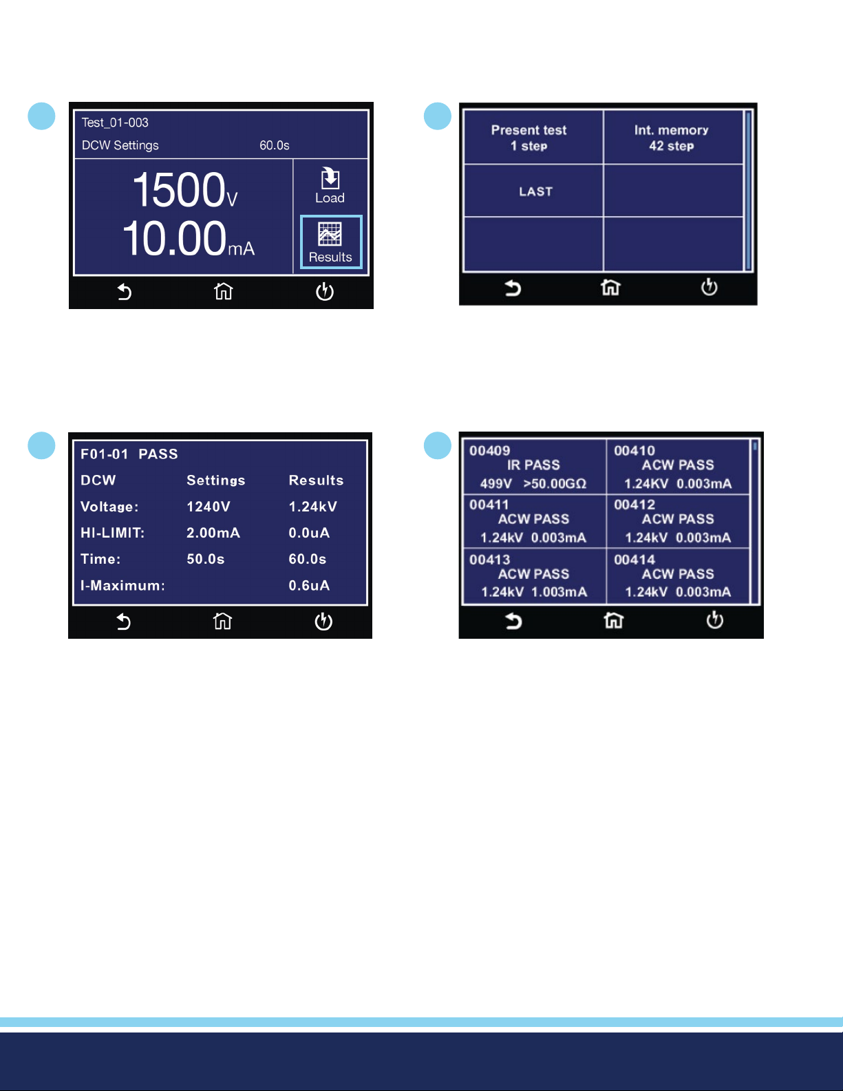
Viewing Test Results
After a test has completed the Results icon will be available on the screen. For example:
1
3
2
4
Select Present Test to view test results from the
current test sequence that was executed. Select any
test step to view more details regarding the test.
© Ikonix USA 2021
Select Int. Memory to view all the test results stored
on the internal memory of the instrument. Scroll
down to view all the test results.
53
Page 54
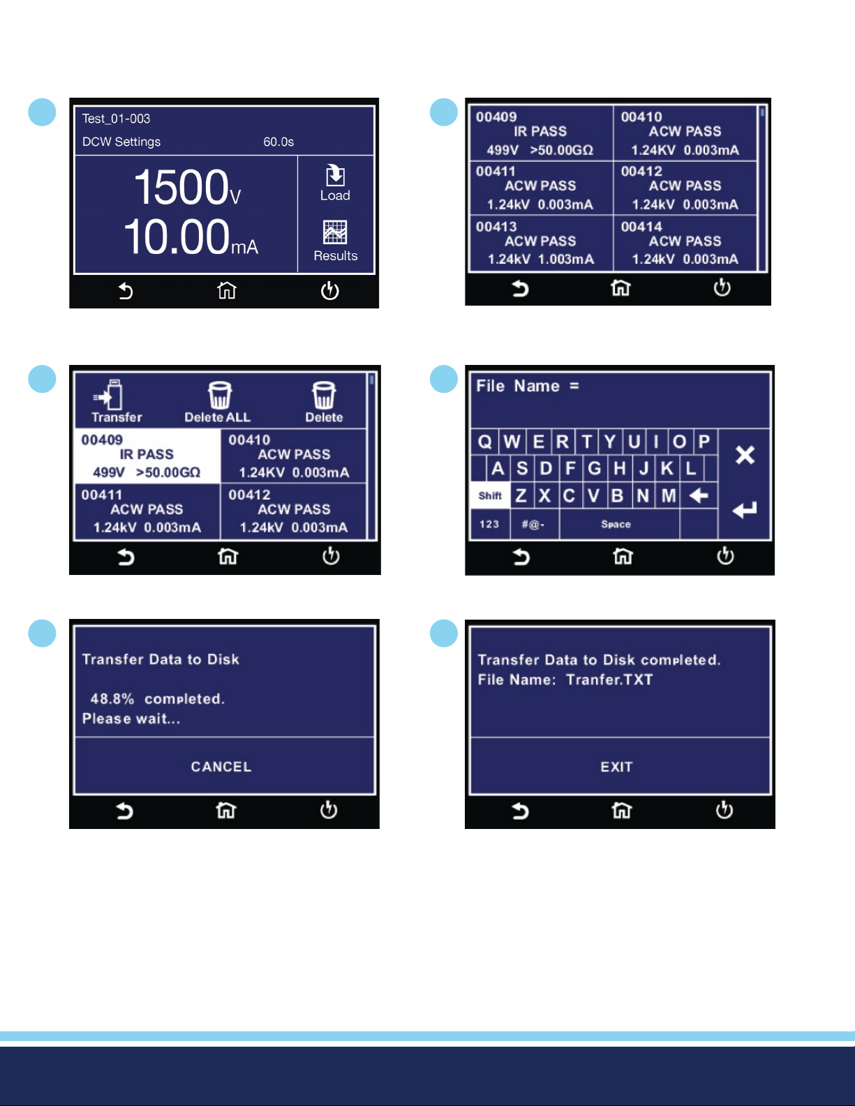
Transfer Test Results
Touch and hold any test step result on the previous screen and the transfer menu will appear. (screen #3 below)
1
From Perform Test screen tap Results icon and
select int. memory.
3
2
Touch and hold any test step result and transfer
menu will appear.
4
Press transfer to begin exporting internal memory
results.
5
Transfer results progress.
From this screen you can transfer All results to a USB disk, delete All results or delete a single result. Selecting Delete ALL will
delete all the test results from the internal memory. Selecting delete will delete a selected step.
To transfer results to a USB disk select the Transfer icon and a new pop up screen will appear where a le name must be entered
for the results le. The results will be saved on the USB disk with this le name:
Once you assign and save a le name the following screen will appear showing the transfer status:
Enter name for Results File.
6
Transfer results complete.
Once the results le transfer is complete a message will appear on the screen conrming the successful transfer along with the
results le name that was previously assigned.
© Ikonix USA 2021
54
Page 55
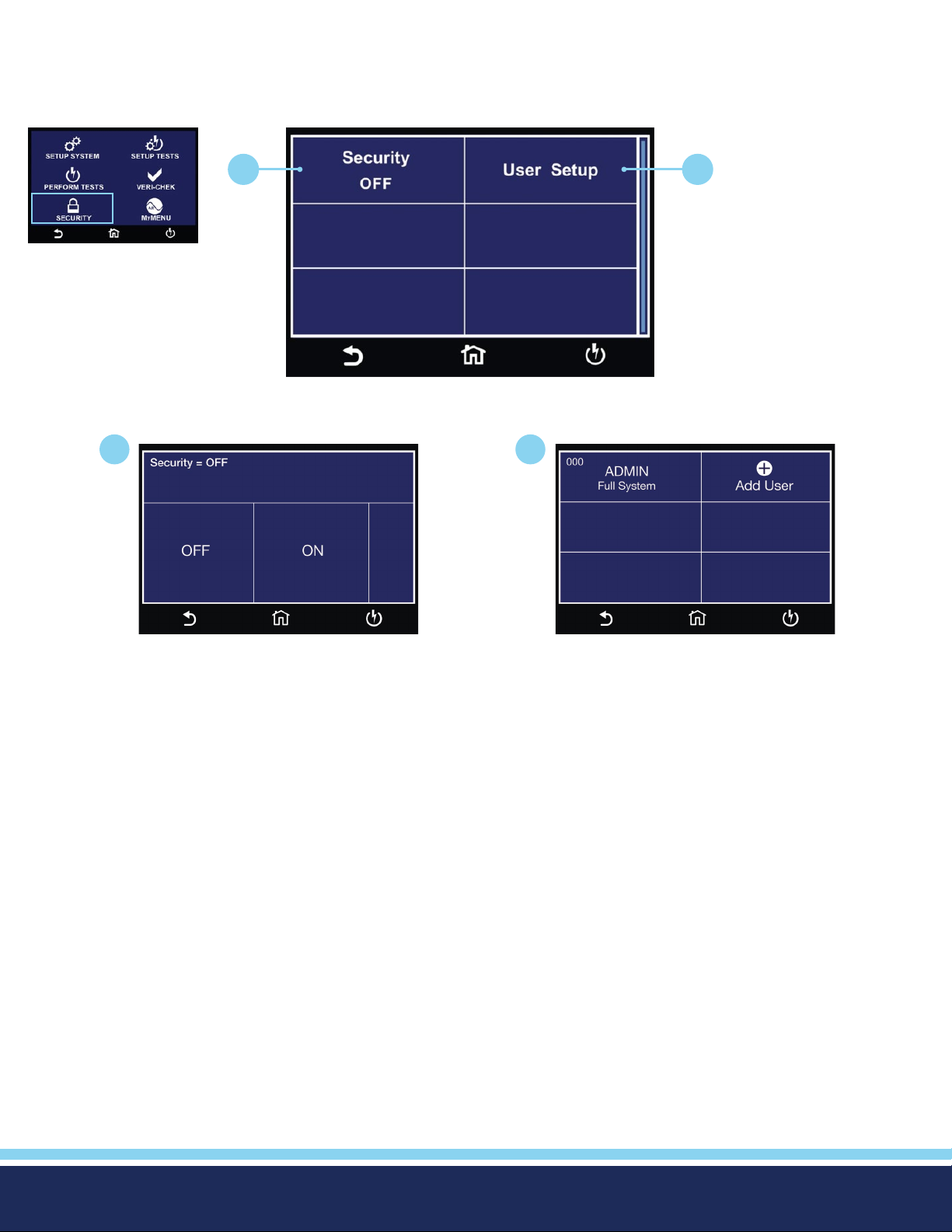
4. Security
Instrument security and user setup screen. The rst option under Security allows you to set Security to ON or OFF.
Setup System Menu
1
1
2
Security Menu
2
Select Security ON or OFF. User Setup Menu.
© Ikonix USA 2021
55
Page 56
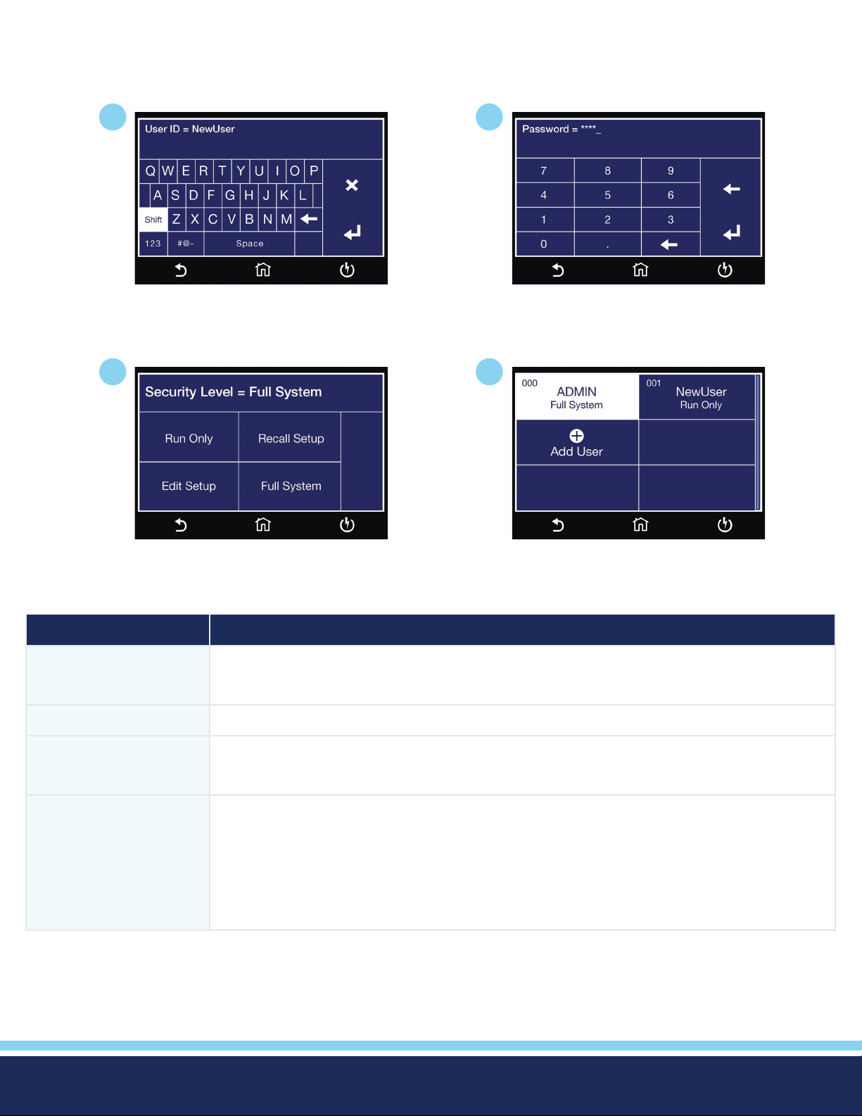
User Setup
The next option under security is User Setup where multiple users can be added and assigned different privileges.
1
Enter New User ID.
1
2
Enter Password.
2
Select Security Level.
Security Level Description
Full System In this mode you have full access level to all instrument setup parameters as well as system
conguration and security levels. Access at this level should be restricted to System
Administrators
Edit Setup In this mode you can load les and edit test parameters.
Recall Setup This mode allows you to load previously congured test les but it does not allow any editing
of the parameters. In this mode you are restricted from access to the “Setup Test Parameters”
screen.
Run Only This is the most restricted mode of user access. You can only initiate a test, reset a failure or abort
a test from the Perform Tests screen.
NOTE: whenever your security level is Run Only, “Single Step” and “Fail Stop” soft keys will be
disabled at the Perform Test screen.
NOTE: whenever your security level is Run Only, you may only start at test step 1.
User Setup Menu updated.
Security – Forgotten Password
If you have forgotten your password you may access all security functions by typing in the number “8000” into the password
eld. The old password cannot be recovered and a new password needs to be entered.
© Ikonix USA 2021
56
Page 57
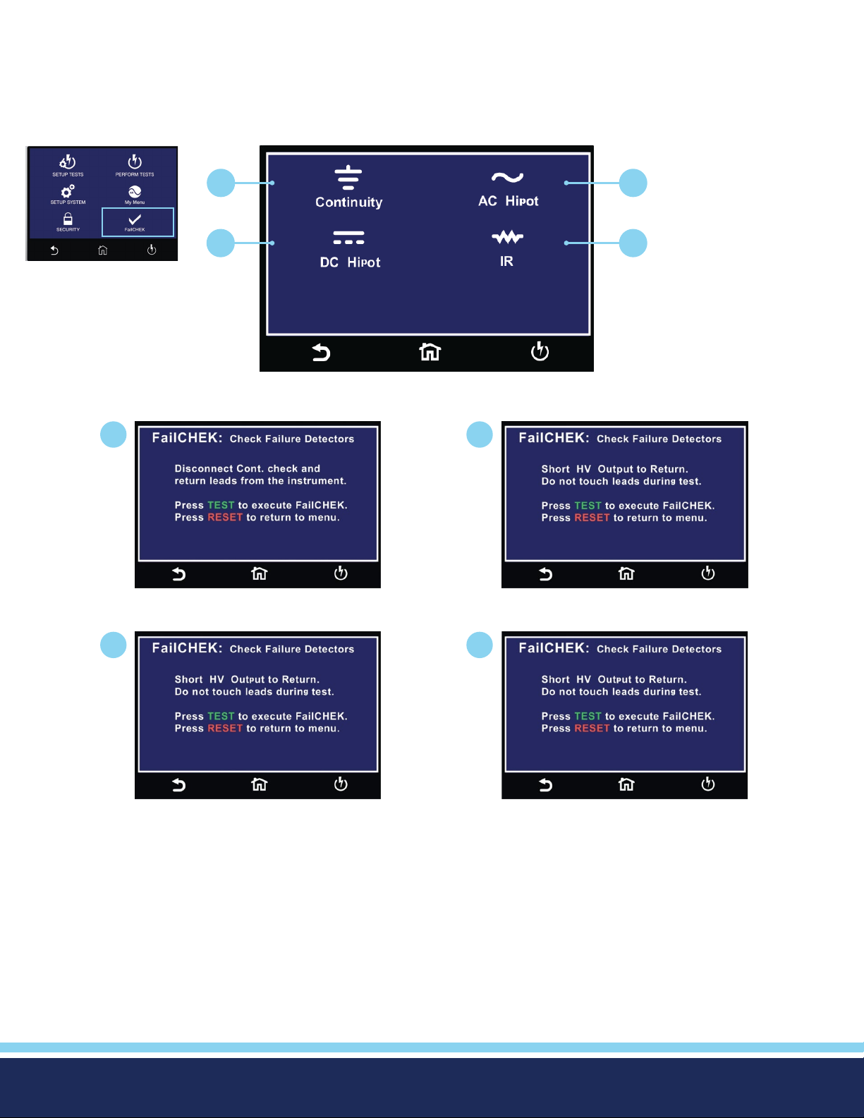
5. FailCHEK
FAILCHEK is the process by which an instrument’s failure detectors are proven to be functioning properly. Safety agencies such
as CSA, UL and TÜV require checking the failure detection circuitry of the electrical safety instrument. To perform FAILCHEK
touch the test icon and follow instructions on the instrument screen.
Main Menu
1
1
2
3 4
FailCHEK Menu
2
3
Continuity FailCHEK screen
DC Hipot FailCHEK screen
AC Hipot FailCHEK screen
4
IR FailCHEK screen
© Ikonix USA 2021
57
Page 58
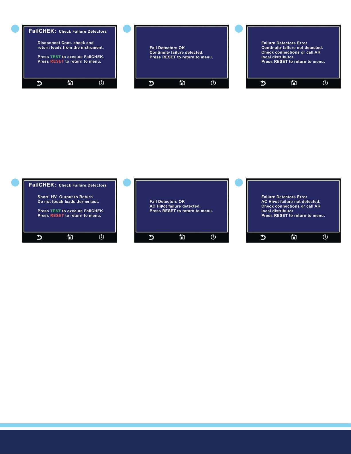
FailCHEK Continuity
1
To perform Continuity FailCHEK
follow on-screen instructions.
FailCHEK AC Hipot
1
2
Continuity Fail Detectors OK screen.
2
3
Continuity Fail Detectors ERROR
screen.
3
To perform AC Hipot FailCHEK
follow on screen instructions.
AC Hipot Fail Detectors OK screen.
AC Hipot Fail Detectors ERROR
screen.
© Ikonix USA 2021
58
Page 59
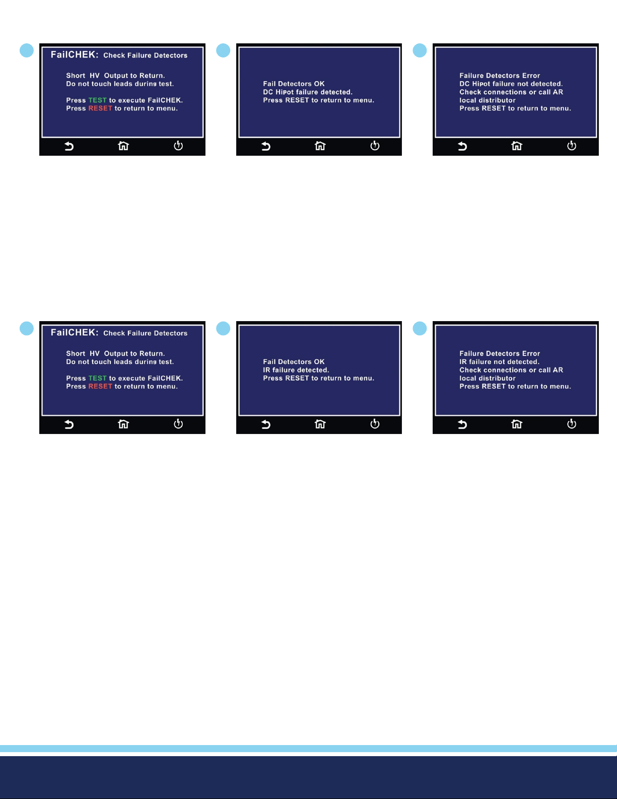
FailCHEK DC Hipot
1
To perform DC Hipot FailCHEK
follow on screen instructions and
press Green TEST Button or Red
RESET to return to previous menu.
FailCHEK Insulation Resistance
1
2
DC Hipot Fail Detectors OK screen.
2
3
DC Hipot Fail Detectors ERROR
screen.
3
To perform IR Hipot FailCHEK follow
on screen instructions and press
Green TEST Button or Red RESET to
return to previous menu.
IR Fail Detectors OK screen.
IR Fail Detectors ERROR screen.
© Ikonix USA 2021
59
Page 60
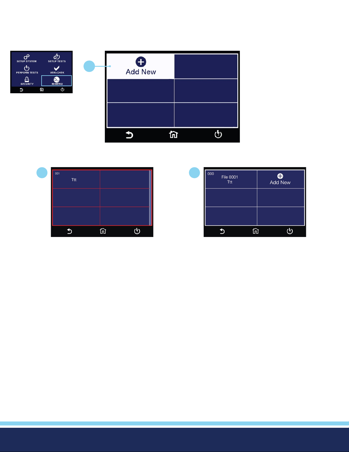
6. MyMenu
The MyMenu function allows the user to congure a custom menu. User can store the desired test les under MyMenu and
access the les by a single touch.
1
Main Menu
Select Add New to add test le to MyMenu
1
Select le to be added to MyMenu. MyMenu Screen.
2
© Ikonix USA 2021
60
Page 61
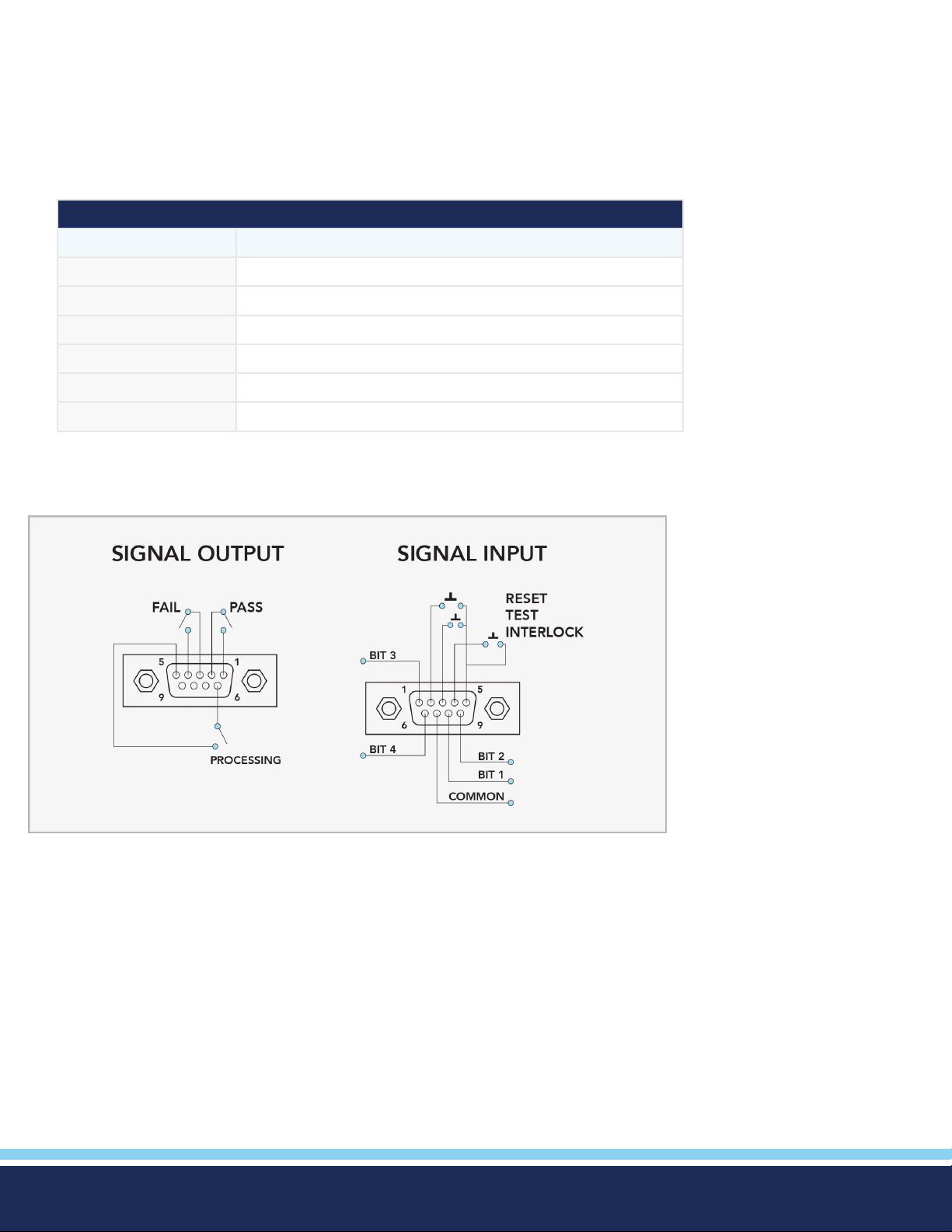
Using Remote I/O and PLC Control
Two 9-pin “D” type connectors mounted on the rear panel provide REMOTE-INPUT-OUTPUT control and information.
• These connectors mate with a standard 9 pin D-sub-miniature connector provided by the user.
• The output mates to a male (plug) connector while the input mates to a female (receptacle) connector.
• For best performance, you should use a shielded cable. To avoid ground loops you should not ground the shield at both
ends of the cable.
Suggested AMP part numbers for interconnecting to the Remote I/O
Part Number Description
205204-4 Plug shell with ground indents
205203-3 Receptacle shell
745254 -7 Crimp snap-in pin contact (for plug)
745253-7 Crimp snap-in socket contact (for receptacle)
745171-1 Shielded cable clamp (for either plug or receptacle)
747784 -3 Jackscrew set (2)
Remote I/O Pinouts
© Ikonix USA 2021
61
Page 62
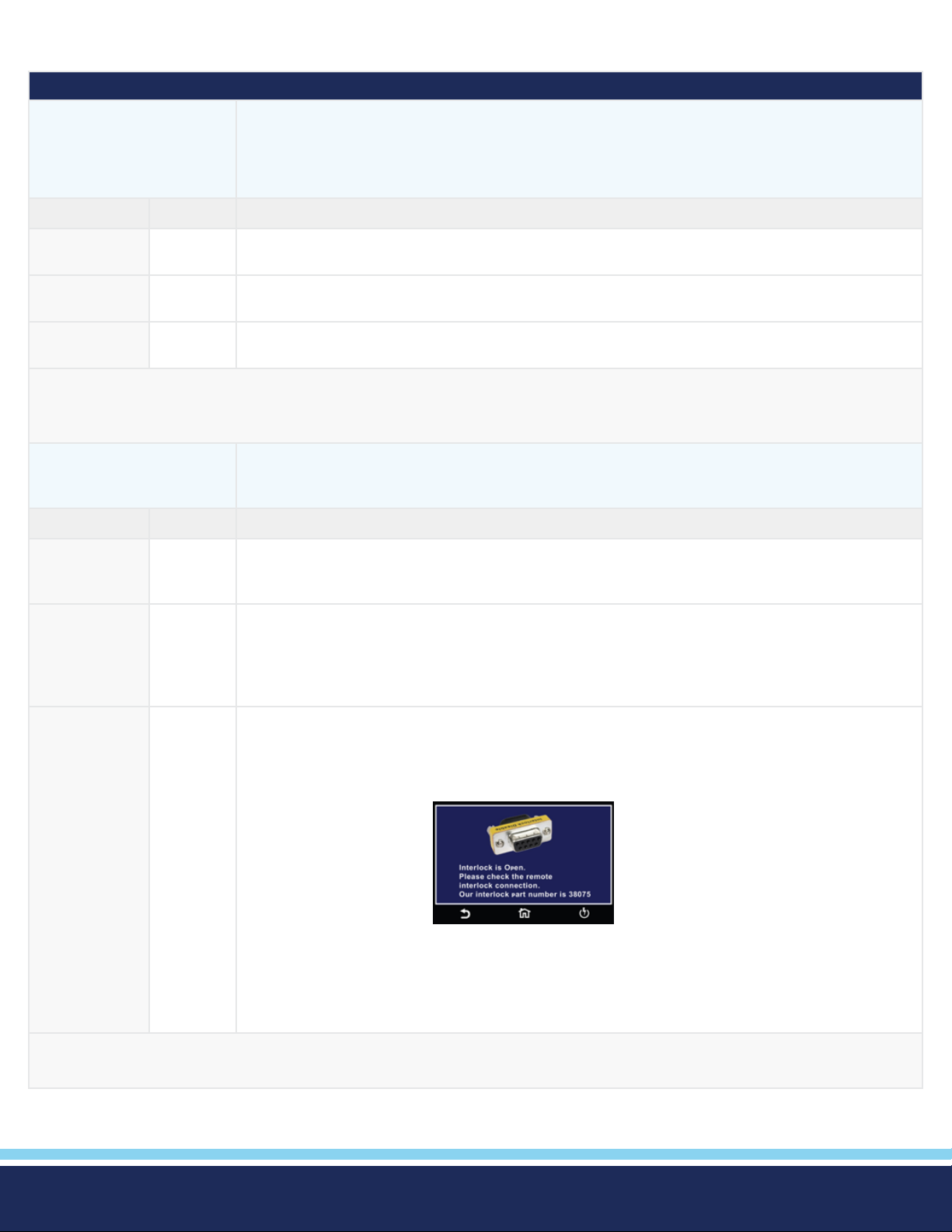
Signals on Remote I/O
REMOTE INPUT/OUTPUT
Remote Output The rear panel connector provides three output signals to remotely monitor PASS, FAIL,
and PROCESSING conditions. The monitoring signals are provided by three normally open
internal relays that toggle ON and OFF to indicate the condition of the instrument. These
are normally open free contacts and will not provide any voltage or current.
Output Signal Pins Description
PASS 1 and 2 The relay contact closes after detecting that the device under test passed all tests. The
connection is opened when the next test is initiated or the reset function is activated.
FAIL 3 and 4 The relay contact closes after detecting that the device under test failed any test. The connection
is opened when the next test is initiated or the reset function activated.
PROCESSING 5 and 6 The relay contact closes while the tester is performing a test. The connection is opened at the
end of the test.
These are normally open free contacts and will not provide any voltage or current. The ratings of the contacts are 1 AAC / 125
VAC (0.5 ADC / 30 VDC). When a terminal becomes active, the relay closes thereby allowing the external voltage to operate an
external device.
Remote Input The Hypot remote connector enables remote operation of the TEST, RESET, and REMOTE
INTERLOCK functions, and allows you to select one of 3 pre-programmed test les.
(7 memories available with added option)
Output Signal Pins Description
TEST 3 and 5 A normally open momentary switch can be wired across pins 3 and 5 to allow remote operation
of the TEST function. A minimum pulse width or contact closure of 20mS is required to guarantee
a test start.
RESET 2 and 5 A normally open momentary switch can be wired across pins 2 and 5 to allow remote operation
of the RESET function. For safety, the front panel RESET button remains active even when a
remote reset switch is connected so that high voltage can be shut down from either location. A
minimum pulse width or contact closure of 50mS is required to guarantee that a running test will
abort.
INTERLOCK 4 and 5 Remote Interlock utilizes a set of closed contacts to enable the tester’s output. The output of the
tester will be disabled under the following conditions:
• If the Interlock contacts are open and the TEST button is pushed
• If the interlock contacts are opened during a test (test will automatically abort)
A pop-up message will be
displayed on the screen:
The tester can still be used without the external interlock device as long as the Interlock
Connector (P/N # 38075 provided with unit) is plugged into the Remote Interface, Signal Input
port. If there is nothing connected to the Remote Interface, Signal Input port to provide a
connection to the interlock, the tester will not perform tests.
When the PLC Remote mode is ON, the tester will respond to simple switch or relay contacts closures. When the PLC Remote
function is ON the TEST button on the front panel will be disabled.
© Ikonix USA 2021
62
Page 63
Remote Signal Inputs and Memory Access
• The Remote File Select function gives you the capability to quickly select and initiate a test remotely.
• You can access rst three (3) pre-programmed test les by connecting pins 1, 6, 8 and 9 to the common pin 7, in different
combinations. (7 memories available with added option)
• The memory select bits should be set simultaneously and remain set for a
minimum of 20ms to guarantee that the correct memory will be selected.
DID YOU KNOW...
• The memory select bits may be set in sequential manner, provided that the time
delay between each bit is less than 4ms.
• When the desired bit pattern has been established it should remain set for a
minimum of 20ms to guarantee that the correct memory will be selected.
• It may be necessary to “OR” the momentary switches (relay contacts) to
prevent incorrect program selection due to timing errors.
REMOTE FILE SELECT TRUTH TABLE
BIT 3 BIT 2 BIT 1 FILE #
0 0 1 01
0 1 0 02
0 1 1 03
1= Momentary Contact closure between BIT and COMMON
0= No Contact closure between BIT and COMMON
The Remote Signal Input connector may
be used with various accessories, including
light curtains, foot switches, and safety
probes. Contact Associated Research for
more information.
Activating memory program functions through the remote connector, selects the program and starts
WARNING
Activation des fonctions de mémoire programme via le connecteur remote , sélectionne le programme et lance le test qui est
préprogrammé dans cette mémoire
CAUTION
Ne pas connecter tension ou de courant aux entrées de signal, cela pourrait provoquer des dommages au circuit de contrôle
the test which is preprogrammed into that memory
Do not connect voltage or current to the signal inputs, this could result in damage to the control
circuitry.
© Ikonix USA 2021
63
Page 64

Appendix A - Installation and Test Operator Information
Installation
1. Unpacking and Inspection
Your instrument ships in a custom foam insulated container. If the shipping carton is damaged, inspect the contents for visible
damage such as dents, scratches or a broken display. If the instrument is damaged, notify the carrier and Associated Research’s
customer care department. Please save the shipping carton and packing material for the carrier’s inspection. Our customer care
department will assist you in the repair or replacement of your instrument. Please do not return your product without rst notifying us and receiving an RMA (return material authorization) number. To receive an RMA number, please contact our
customer care department at 1-800-858-TEST (8378).
2. Safe Lifting and Carrying Instructions
Proper methods of lifting and carrying can help to protect against injury. Follow the recommendations below to ensure that
instruments are handled in a safe manner.
• Determine if the instrument can be lifted by one individual or requires additional support.
• Make sure that your balance is centered and your feet are properly spaced, shoulder width apart behind the instrument.
• Bend at the knees and make sure your back is straight.
• Grip the instrument with your ngers and palms and do not lift unless your back is straight.
• Lift up with your legs, not your back.
• Keep the instrument close to your body while carrying.
• Lower the instrument by bending your knees. Keep you back straight
3. Contents of the Carton
DESCRIPTION AR PART NUMBER
®
Hypot
High Voltage Cable 04040A-08
Return Cable 0210 0A-13 (Q t y.2)
USB Cable AB-Type 1.8m 39066
Fuse 37880
Line Cord
Adapter Box
Interlock Connector 38075
8GB USB Flash Drive 39571
Instrument 38XX
38430 (Model 3880)
*
*
33189 Standard
36544 Standard
*
The Line Cord listed is American. Other combinations of the Line Cord are available upon request.
© Ikonix USA 2021
64
Page 65
Use only accessories that meet the manufacturer’s specication.
WARNING
Utiliser uniquement des accessoires conformes aux spécications du fabricant.
4. Preparation for Use
Power Requirements
This instrument requires a power source of either 115 volts AC ± 10%, 50/60 Hz single phase or 230 volts AC ±10%, 50/60 Hz
single phase. See section for Rear Panel Controls for an image of the rear panel.
Do not replace the power supply cord with an improperly rated cord. For North American: A UL listed
CAUTION
125VAC, 10A, number 16 gauge (or 125VAC, 15A, number 14 gauge) wire or larger, and the length of the cord does not exceed 2
m must be used. For European: A certied power supply cord not lighter than light PVC sheathed exible cord according to IEC
60227, designation H03 VV-F or H03 VVH2-F (for equipment mass not exceeding 3 kg), or H05 VV-F or H05 VVH2-F2 (for equipment mass exceeding 3 kg), and be rated for at least 3G 0.75 mm² (for rated current up to 10 A) or 3G 1.0mm² (for rated current
over 10 A up to 16 A) wire or larger, and the length of the cord does not exceed 2 m must be used.
Ne remplacez pas le cordon d’alimentation avec un cordon mal classé . Pour l’Amérique du Nord:
Une UL et CSA marqué cordon d’alimentation doit être olariz avec l’instrument aux États-Unis et
Canada . Le cordon d’alimentation doit comporter une che mâle NEMA5-15 de style , SVT ou ensembles SJT de la moelle ,
et être classé pendant au moins 125VAC , 10ª , numéro de calibre 16 ( ou 125VAC , 15ª , numéro de calibre 14 ) l ou plus, et la
longueur de le cordon ne dépasse pas 2 m doit être utilisé . Pour européenne : Un cordon d ‘alimentation certié , pas plus léger
que le PVC lumière câbles souples sous gaine selon la norme IEC 60227 , la désignation H03 VV- F ou
H03 VVH2 – F ( pour la masse de l’équipement ne dépassant pas 3 kg) , ou H05 VV- F ou H05 VVH2 – F2 (masse d’ équipement
de plus de 3 kg) , et être prévus pour au moins 3G 0,75 mm ² ( pour courant nominal jusqu’à 10 A ) ou 3G 1.0mm² ( pour l nominale ou plus actuelle plus de 10 A à 16 A) , et la longueur du cordon ne doit pas excéder 2 m doit être utilisé.
and CSA labeled power cord must be used with the instrument in the United States and Canada. The
power cord must include a NEMA5-15 style male plug, SVT or SJT cord sets, and be rated for at least
The Hypot must be connected to a good ground. Be certain that the power wiring is properly polar-
WARNING
L’Hypot doit être relié à un bon sol. Assurez-vous que le câblage d’alimentation est correctement polarisé et que la bonne résistance à la terre est en place.
ized and that the proper low resistance bonding to ground is in place.
5. Power Cable
The instrument is shipped with a line cord containing a protective earth ground. When the line cord is connected to an
appropriate AC power source the cable will connect the chassis to earth ground.
Only insert the main plug in a socket outlet with a protective ground (earth) contact. This protective
WARNING
La che principale ne doit être insérée dans une prise de courant avec une masse (terre ) avec système de protection . Cette terre
de protection ne doit pas être vaincu par l’utilisation d’ une rallonge sans conducteur de protection.
This instrument is shipped with a three-wire power cable. When this cable is connected to an appropriate AC power source, this
cable connects the chassis to earth ground. The type of power cable shipped with each instrument depends on the country of
destination.
ground must not be defeated by the use of an extension cord without a protective conductor.
© Ikonix USA 2021
65
Page 66
Operating Environment
This equipment is intended for indoor use only. The equipment has been evaluated according to Installation Category II
and Pollution Degree 2 as specied in IEC 664.
Operate this instrument in environments with the following limits:
Temperature ......................... 41° - 104° F (5° - 40°C)
Relative humidity .................. 0 – 80%
Altitude ................................. 6560 feet (2,000 meters)
Do not block any ventilation openings to prevent over heating of the equipment. Keep the ventilation
WARNING
Ne pas bloquer les ouvertures de ventilation pour éviter la surchauffe de l’équipement Gardez les fentes de ventilation découverts au cours de l’opération. Ne pas le faire pourrait entraîner l’instrument de surchauffer et endommager les composants
internes.
slits uncovered during operation. Failure to do so could cause the instrument to overheat and may
damage internal components.
Storage and Shipment
Store or ship this instrument in environments with the following limits:
Temperature ......................... -40° - 167° F (-40° - 75°C)
Altitude ................................. 50,000 feet (15,240 meters)
Also protect this instrument against temperature extremes that may cause condensation within the instrument.
Failure to operate this instrument within the specied conditions could result in damage.
CAUTION
L’incapacité à manipuler cet instrument dans les conditions spéciées peuvent entraîner
des dommages.
If the instrument is used in a manner not specied by the manufacturer, the protection provided by the instrument may be
impaired.
More Information
For more information on test operator and workstation safety please visit the Events and Training section of our website at
www.arisafety.com
Test Operator and Safety Considerations
1. Qualications
This instrument generates voltages and currents that can cause harmful or fatal electric shock and
WARNING
Cet instrument produit des tensions et des courants qui peuvent causer des chocs électriques
dangereux ou mortel et ne doivent être exploitées par un travailleur qualié formé à son olarize ve . L’opérateur doit comprendre
les principes fondamentaux électriques de tension, courant et la
résistance.
must only be operated by a skilled worker trained in its use. The operator should understand the
electrical fundamentals of voltage, current, and resistance.
Do not touch the device under test, high voltage test lead, alligator clip, or clip insulator once the test
WARNING
Ne touchez pas l’appareil sous test, le l de test haute tension, le crocodile ou l’isolateur de clip une fois le test lancé.
© Ikonix USA 2021
has been started.
66
Page 67
Do not touch the front panel when testing or after a malfunction has occurred.
WARNING
Ne olariz pas la face avant lors de l’essai ou après un dysfonctionnement s’est produit.
The operator should understand the electrical fundamentals of voltage, current, and resistance.
2. Safety Procedures
Operators should be thoroughly trained to follow these and all other applicable safety rules and procedures before they begin
a test. Defeating any safety system should be treated as a serious offense and should result in severe penalties, such as removal from the Hipot testing job. Allowing unauthorized personnel in the area during a test should also be dealt with as a serious
offense.
Refer to the following standards for more information:
• NFPA 70E
• OSHA 1910 subpart (S)
• EN50191
3. Dress
Operators should not wear jewelry that could accidentally complete a circuit.
WARNING
Do not observe ESD protocols while performing electrical safety tests. Intentionally grounding the
test operator could lead to a harmful or fatal electric shock.
Protocoles de l’EDD ne devraient pas être respectées lors de l’exécution des tests de sécurité électrique. Intentionnellement à la
terre à l’opérateur de test pourrait conduire à un choc électrique dangereux ou mortel.
4. Medical Restrictions
Inform personnel with heart ailments or devices such as pacemakers that the voltages and currents generated by the instrument
are very dangerous. If contacted, the instrument may cause heart-related problems. Please have the test operator consult a physician for recommendations.
5. Test Station
Location
Select an area away from the main stream of activity which employees do not walk through in performing their normal duties.
If this is not practical because of production line ow, then the area should be roped off and marked for HIGH VOLTAGE
TESTING. No employees other than the test operators should be allowed inside. If benches are placed back-to-back, be
especially careful about the use of the bench opposite the test station. Signs should be posted: “DANGER - HIGH VOLTAGE
TEST IN PROGRESS - UNAUTHORIZED PERSONNEL KEEP AWAY.”
The mains plug is used as the disconnecting device and shall remain readily operable. The socket-out-
WARNING
let shall be installed. Near the equipment and shall be easily accessible.
La che secteur est utilisée comme dispositif de déconnexion et doit rester facilement opérationnelle. La prise de courant doit
être installée. Près de l’équipement et doit être facilement accessible.
© Ikonix USA 2021
67
Page 68
Work Station
Perform the tests on a non-conducting table or workbench, if possible.
There should not be any metal in the work area between the operator and the location where products being tested will be
positioned.
Position the instrument so the operator does not have to reach over the product under test to activate or adjust the instrument. If
the product or component being tested is small, it may be possible to construct guards or an enclosure, made of a
non-conducting material such as clear acrylic, such that the item being tested is within the guards or enclosure during the test,
and t them with switches so that the instrument will not operate unless the guards are in place or the enclosure closed. The
outlet which is used to provide power to the instrument should be easily accessible.
Keep the area clean and uncluttered. All test equipment and test leads not absolutely necessary for the test should be removed
from the test bench and put away. It should be clear to both the operator and to any observers which product is being tested,
and which ones are waiting to be tested or have already been tested. If the instrument is used in a matter not specied by
Associated Research the protection provided by the instrument may be impaired.
Do not perform Hipot tests in a combustible atmosphere or in any area where combustible materials are present.
KEY SAFETY POINTS TO REMEMBER
• Keep unqualied and unauthorized personnel away from the test area.
• Arrange the test station in a safe and orderly manner.
• Never touch the product or connections during a test.
• In case of any problem, turn off the high voltage rst.
• Properly discharge any item tested with DC before touching connections.
© Ikonix USA 2021
68
Page 69
Appendix B – Instrument Specications
Models 3805, 3865, 3870 and 3880 Functional Specications
Unless otherwise stated, accuracy’s are relative to a laboratory standard measurement.
INPUT
Voltage 100 - 120VAC / 200 - 240VAC±10% Auto Range
Frequency 50/60Hz ± 5%
Fuse 3805, 3865 and 3870: 3.15A / 250VAC Fast-Blow
3800: 15A / 250VAC Fast- Blow
AC WITHSTAND VOLTAGE (All Hypot Models)
Range Resolution Accuracy
Output Voltage, AC 0 - 5000 1 ± (2% of setting + 5V)
Output Frequency 50Hz/60Hz ± 0.1% , User Selection,
Output Waveform Sine Wave , Crest Factor = 1.3 - 1.5
Short Circuit Protection 3805, 3865 and 3870: minimum current 22mA RMS at short circuit, Response time < 2ms
3880: Output short Circuit current >200mA, Response time < 2ms
Output Regulation ± (1% of output + 5V), From no load to full load and Low Line to High Line
(combined regulation)
SETTINGS
Auto Range
HI-Limit current, mA 0.00 – 20.00
0.00 – 99.99 (Model 3880)
LO-Limit current, mA 0.000 - 9.999
0.000 – 9.999 (Model 3880)
Ramp-Up Timer, second 0.1 - 999.9
Ramp-Down Timer, second 0.0 - 999.9
Dwell Timer, second 0, 0.2 - 999.9 (0=continuous)
Ground Continuity Current Current: DC 0.1 A ± 0.01A, xed
Max. Ground Resistance: 1.0 Ω ± 0.1Ω
Ground Continuity HI-Limit
LO-Limit
Offset
0.00 - 1.50
0.00 - 1.50
0.00 - 0.50
0.01
0.01
0.001
0.001
0.1 ± (0.1% + 0.05 sec)
0.01
± (2% of setting + 2 counts)
± (2% of setting + 6 counts)
± (2% of setting + 2 counts)
± (2% of setting + 6 counts)
± (3% of setting + .02Ω)
Arc Detection 1 - 9 ranges (9 = highest sensitivity)
© Ikonix USA 2021
69
Page 70
DC WITHSTAND VOLTAGE (3865 and 3870 Only)
Output Voltage, DC 0 - 6000 1 ± (2% of setting + 5V)
DC Output Ripple <5 % ( 6KV / 7500 μA at Resistive Load)
Short Circuit Protection Minimum current 8250 μA AVG at short circuit, Response time < 2ms
SETTINGS
Auto Range
HI-Limit, current, μA 0 – 7500 1
LO-Limit, current, μA 0.0 – 999.9 0.1
± (2% of setting + 2 counts)
Ramp-Up Timer, second 0.1 - 999.9
Ramp-Down Timer, second 0, 1.0-999.9 (0 = OFF)
0.1 ± (0.1% + 0.05 sec)
Dwell Timer, second 0, 0.4 - 999.9, (0=continuous)
Ramp-HI, current, µA 0.0 – 999.9 0.1
1000 – 7500 1
Charge-LO, current 0.0 - 350.0 μA DC or Auto Set
Discharge Time ≤ 50 ms for no load, < 100 ms for capacitor load
(all capacitance values in MAX load spec below)
Maximum Capacitive Load
DC Mode
1µF < 1KV 0.08µF < 4KV
0.75µF < 2KV 0.04µF < 5KV
0.5µF < 3KV 0.015µF < 6KV
Ground Continuity Current Current: DC 0.1 A ± 0.01A, xed
Max. Ground Resistance: 1.0Ω ± 0.1Ω
Ground Continuity HI-Limit
LO-Limit
Offset
0.00 - 1.50
0.00 - 1.50
0.00 - 0.50
± (2% of setting + 2 counts)
± (3% of setting + .02Ω)
Arc Detection 1 - 9 ranges (9 = Highest sensitivity)
© Ikonix USA 2021
Continued on next page
70
C
Page 71
INSULATION RESISTANCE (Model 3870)
Output Voltage, DC 30 - 1000 1 ± ( 2% of setting + 5V)
SETTINGS
HI and LO-Limit, resistance,MΩ0, 1.00 - 99.99
(HI – Limit: 0 = OFF)
100.0 - 999.9 0.1 1000 - 9999,
1000-50000 1 10000 - 50000,
Ramp-Up Timer, second 0.1 – 999.9
Ramp-Down Timer, second 0.0, 1.0-999.9 (0 = OFF)
Dwell Timer, second 0, 0.5 - 999.9 or 0
(0=continuous)
Delay Timer, second 0.5 - 999.9 (0 = OFF)
Charge-LO, current, µA 0.5 - 3.50 or Auto Set
MEASUREMENT
Range Resolution Accuracy
0.01 30-499V
1.00 -999.9, ± (8% of setting + 2 counts)
500-1000V
1.00 – 999.9, ± (2% of setting + 2 counts)
± (5% of setting + 2 counts)
± (15% of setting + 2 counts)
0.1 ± (0.1% + 0.05 sec)
Voltage, KV(AC/DC) 0.00 - 6.00 0.01 ± ( 1.5% of reading) ≥ 500V
± ( 1.5% of reading +1 count) ≤ 500V
Voltage, VDC (IR only) 30 - 1000 0.01 ± (1.5% of reading + 5V)
Accuracy for AUTO range
AC Current, mA 0.000 - 4.000 RMS 0.001
± (2% of reading + 2 counts)
3.50 - 30.00 RMS 0.01
3.50 - 99.99 RMS (3880 only)
0.01
± (2% of reading + 6 counts)
DC Current, µA 0.0 - 400.0 DC 0.1
DC Current, mA 0.350 - 4.000 DC 0.001
± (2% of reading + 2 counts)
3.50 - 7.50 DC 0.01
© Ikonix USA 2021
Continued on next page
71
C
Page 72

Resistance, MΩ (IR) 30 - 99V 100 - 499V 500 - 1000V
1.000 - 1.999 1.000 - 1.999 1.000 - 9.999 0.001
2.00-19.99 2.00 - 19.99 10.00 - 99.99 0.01
20.0 - 199.9 20.00 - 199.9 100.0 - 999.9 0.1 1000 - 9999,
200 - 10000 200 - 20000 1000 - 50000 1 10000 - 50000,
GENERAL SPECIFICATIONS
Safety Agency Listing CE, cTUVus, RoHS2
PLC Remote Control Input: Test, Reset, Interlock, Recall File 1 through 3(Standard),
Recall File 1 through 7(Option).
Hardware Interlock- Direct control sine wave and amplier relay off when Interlock signal is
disabled.
Output:- Pass, Fail, Test-in-Process
(Output relay contact ratings is 1AAC/125VAC, 0.5ADC/30VDC)
30 - 499V
1.00 - 999.9,
± (8% of reading + 2 counts)
500 - 1000V
1.00 - 999.9,
± (2% of reading + 2 counts)
± (5% of reading + 2 counts)
± (15% of reading + 2 counts)
Memory 50 steps
1500 test results
Color LCD 4.3” Color Display (Touch Panel)
GFI Built-in Smart GFI circuit,
GFI trip current 450 μA.
HV shut down speed: <1mS
Multinational language User interface available in English, Traditional Chinese, Simplied Chinese, Turkish, Portuguese,
Spanish, German, French
Interface Standard: USB
Security (Standard Password
Protection)
Alarm Volume Setting Range: 0 - 9 ; 0 = OFF, 1 is softest volume, 9 is loudest volume
Calibration Software and adjustments are made through the front panel. Automatic Calibration alert
Environment Temperature: 0 - 40°C, Humidity: 20 - 80%
Dimension Tilt up front feet
Programmable User ID and Password capability to avoid unauthorized access to test set-up
program.
function to signal operator when the next calibration is due.
Not rack mountable with HYAMP Series 31XX
Dimensions (W x H x D)
8.46 x 3.47 x 11.81 in (215 x 88.1 x 300 mm)
16.93 x 5.20 x 11.81 in (430 x 132 x 300 mm) – Model 3880
Weight 3880 = 50.71lb (23Kg)
3805, 3865, 3870 = 12lb (5.6Kg)
Why use the term “Counts”?
Associated Research publishes some specications using COUNTS which allows us to provide a better indication of the
instrument’s capabilities across measurement ranges. A COUNT refers to the lowest resolution of the display for a given
measurement range. For example, if the resolution for voltage is 1V then 2 counts = 2V.
© Ikonix USA 2021
72
Page 73
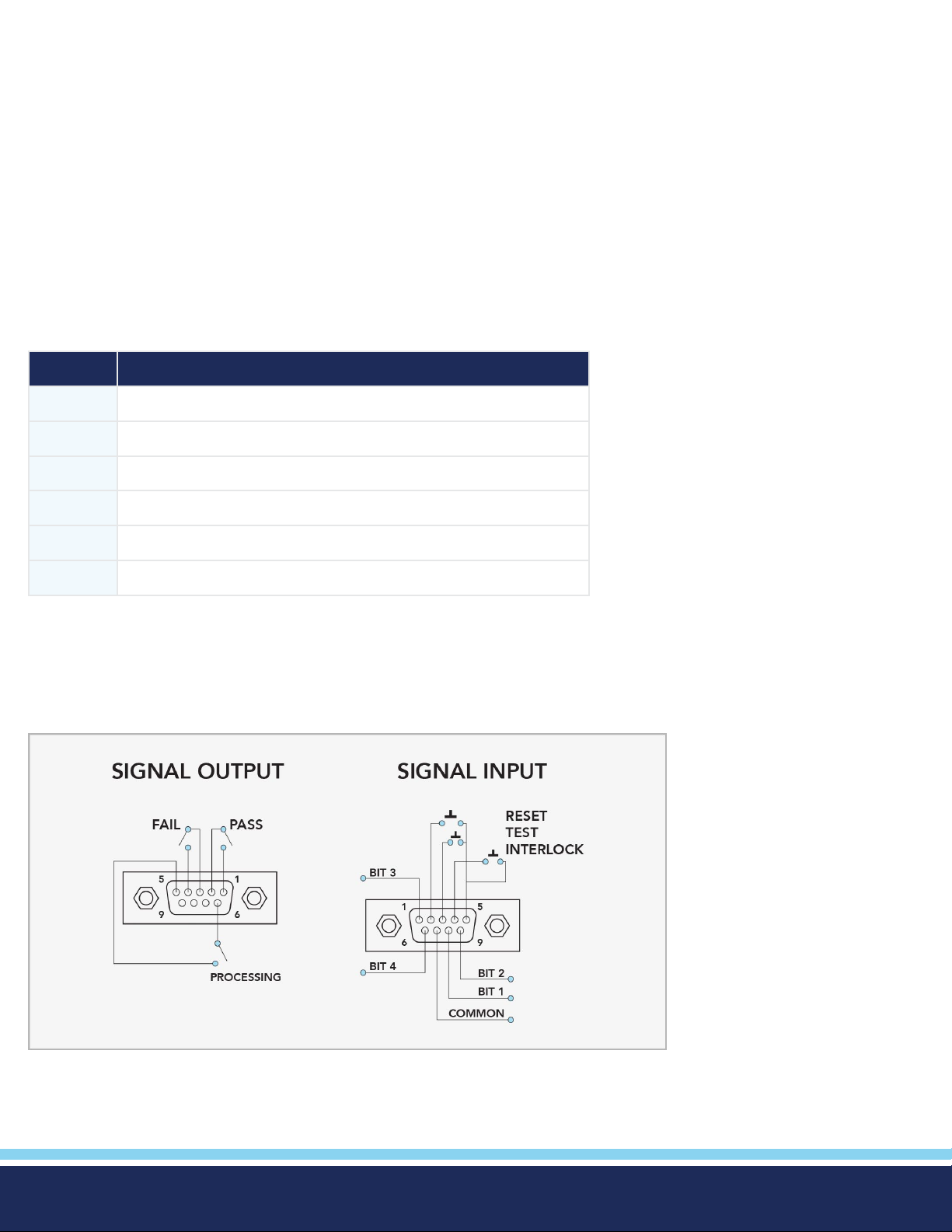
Appendix C - Options
Introduction
This section contains a list and descriptions of available factory installed options at the time of this printing. The list of options
contains an option code number which can be referenced on the model option label on the rear panel of the unit when options
are present.
Model Option Label
On the rear panel of the instrument, you will nd a label that contains the option code.
For example, your options code will appear as follows:
tted with option 01 OPT: 01
tted with option 01 and 02 OPT: 0102
Hypot Options
CODE DESCRIPTION
04 3mA AC/DC Output
05 5mA AC/DC Output
06 5Ω Continuity
14 Mimic H3 Command Set
15 PLC Ready Output
16 7 Memory Remote Select
16 7 Memory Remote Select
© Ikonix USA 2021
73
Page 74
Remote Signal Inputs and Memory Access
• The Remote File Select function gives you the capability to quickly select and initiate a test remotely.
• You can access rst three (3) pre-programmed test les by connecting pins 1, 8 and 9 to the common pin 7, in different
combinations. (7 memories available with added option)
• The memory select bits should be set simultaneously and remain set for a
minimum of 20ms to guarantee that the correct memory will be selected.
• The memory select bits may be set in sequential manner, provided that the
time delay between each bit is less than 4ms.
• When the desired bit pattern has been established it should remain set for a
minimum of 20ms to guarantee that the correct memory will be selected.
• It may be necessary to “OR” the momentary switches (relay contacts) to
prevent incorrect program selection due to timing errors.
REMOTE FILE SELECT TRUTH TABLE
BIT 3 BIT 2 BIT 1 FILE #
0 0 1 01
0 1 0 02
0 1 1 03
1 0 0 04
DID YOU KNOW...
The Remote Signal Input connector may
be used with various accessories, including
light curtains, foot switches, and safety
probes. Contact Associated Research for
more information.
1 0 1 05
1 1 0 06
1 1 1 07
1= Momentary Contact closure between BIT and COMMON
0= No Contact closure between BIT and COMMON
Activating memory program functions through the remote connector, selects the program and starts
WARNING
Activation des fonctions de mémoire programme via le connecteur remote , sélectionne le programme et lance le test qui est
préprogrammé dans cette mémoire
CAUTION
Ne pas connecter tension ou de courant aux entrées de signal, cela pourrait provoquer des dommages au circuit de contrôle
the test which is preprogrammed into that memory
Do not connect voltage or current to the signal inputs, this could result in damage to the control
circuitry.
© Ikonix USA 2021
74
Page 75
14 Mimic H3 Command Set
The Mimic H3 Command Set option for the new Hypot allows you to emulate the Hypot III making it a drop-in replacement for
the older model. The new interface commands and structure of the Hypot can emulate those of the Hypot III interface. This will
allow Hypot III users to integrate the new model into existing test systems easier. For a complete list of bus commands for this
option refer to the Hypot III product manual.
06 5Ω Continuity
The 5Ω Continuity option increases the Ground Continuity maximum limit from 1.5Ω to 5Ω and increases the Ground Continuity
offset range from 0.0Ω – 0.50Ω to 0.0Ω – 0.50Ω. The following specications have been changed for this option.
Output Current, DC 0.1A ± 0.01A, xed
HI-Limit, resistance, Ω 0.00 - 5.00 0.01
LO-Limit, resistance, Ω 0.00 - 5.00 0.01
Offset resistance, Ω 0.00 - 1.00 0.01 ± (3% of setting + 0.02 Ω)
04 3mA AC/DC Output
The 3 mA AC Output option limits the AC Dielectric Withstand Mode output current with software control. The trip points are
adjusted to a maximum of 3 mA and the software has been modied so the high-speed maximum current shutdown is xed at 3
mA. The following table shows the specications for this option:
3mA AC / DC Output
AC WITHSTAND VOLTAGE
SETTINGS
HI and LO-Limit Current, mA 0.000-3.000 0.001 ± (2% of setting + 6 counts)
MEASUREMENT
HI and LO-Limit (Total), Current, mA 0.000-4.000 RMS 0.001 ± (2% of setting + 2 counts)
3.50-5.00 mA RMS 0.01
Short Circuit Protection Minimum current 3.5mA RMS at short circuit, Response time < 2ms
DC WITHSTAND VOLTAGE
SETTINGS
Current, uA HI-Limit 0 - 3000 1 ± (2% of setting + 2 counts)
LO-Limit 0 - 999.9 0.1
DC Current, μA 0.0 – 400.0 DC 0.1 ± (2% of setting + 10 counts)
(0.000 - 565.7 Peak) Low Range is
ON
DC Current, mA 0.350 – 4.000 DC 0.001 ± (2% of setting + 2 counts)
3.50 - 5.00 RMS 0.01
Short Circuit Protection Minimum current 5.8mA DC at short circuit, Response time < 2ms
© Ikonix USA 2021
75
Page 76
15 PLC Ready Output
The PLC Ready Output option creates a signal that acts as an instrument power-on indicator. The signal is available through the
Remote I/O output connector which is located on the back of the instrument. This option closes the relay contact between pin
(1) and pin (2) on the output connector once the instrument is powered on. The PLC Ready Output signal replaces the Pass signal
that is present on the standard instrument.
It should be noted that the term “Ready” in “PLC Ready Output” only implies that the instrument is powered on. To perform a
test, it should be veried that an interlock device is used or the interlock disable connector that was provided with the instrument
is installed, and that there are no failure indicators active on the instrument. For more information on the Remote I/O signals/
connections and Remote Interlock refer to section Using Remote I/O and PLC Control.
05 5mA AC/DC Output
The 5mA Output option limits the output current with software control. The trip points are adjusted to a maximum of 5mA and
the software has been modied so the high-speed maximum current shutdown is xed at 5mA. The following table shows the
specications for this option:
5mA AC / DC Output
AC WITHSTAND VOLTAGE
SETTINGS
HI and LO-Limit, current, mA 0.000-5.000 0.001 ± (2% of setting + 2 counts)
MEASUREMENT
HI and LO-Limit (Total), current, mA 0.000-4.000 RMS 0.001 ± (2% of setting + 2 counts)
3.50 - 5.00 mA RMS 0.01
Short Circuit Protection Minimum current 5.8mA RMS at short circuit, Response time < 2ms
DC WITHSTAND VOLTAGE
SETTINGS
HI and LO-Limit, current, uA 0 - 5000 1 ± (2% of setting + 2 counts)
0 - 999.9 0.1
MEASUREMENT
DC Current, μA 0.0 - 400.0 DC 0.1
DC Current, mA 0.350 – 4.000 DC 0.001
3.50 - 5.00 RMS 0.01
Short Circuit Protection Minimum current 5.8mA DC at short circuit, Response time < 2ms
± (2% of setting + 2 counts)
© Ikonix USA 2021
76
Page 77
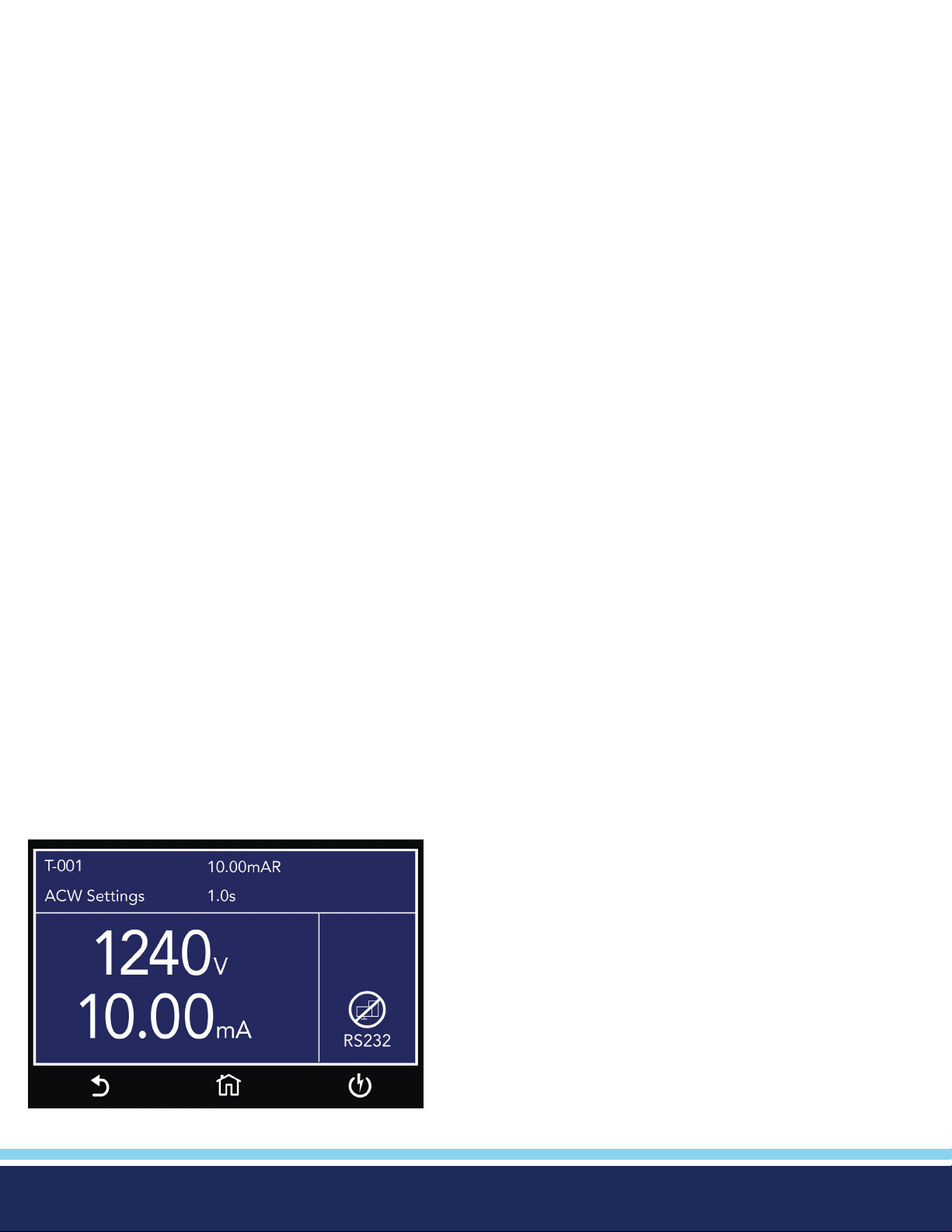
Appendix D - Remote BUS Interface: USB
This section provides information on the proper use and conguration of the bus remote interface. The USB remote interface is
standard on the Hypot.
The USB interface requires you to download a driver in order for the instrument to recognize the USB interface.
The driver can be found on the Associated Research website:
http://www.arisafety.com/products/software/USB-driver.aspx
Click on “USB/RS-232 Driver” to download the driver. This link contains an automatic extract and install program. Follow the
instructions of the installation program to initialize the driver install. NOTE: The USB port acts as a USB to RS-232 converter.
As a result, the PC will recognize the USB port as a virtual COM port.
USB Interface
This interface provides all of the control commands and parameter setting commands of the GPIB interface with the exception of
some of the 488.2 Common Commands and SRQ capability. All commands can be found in USB Command List. The identication command *IDN and the Status Reporting commands are also available through USB.
Communications Port Conguration
The COM port should have the following conguration:
• 38400 baud
• 8 data bits
• 1 stop bit
• No parity
This interface does not support XON/XOFF protocol or any hardware handshaking.
Disconnect USB Communication Icon
Once the USB communication to the instrument is established the front panel touch screen operations will be restricted and a
new icon will appear on the bottom right of the screen. To regain access to the front panel touch screen, rst stop any active
communication from a PC and next touch the Disconnect RS-232 icon. This icon will reappear if there is an active communication
via the USB port.
© Ikonix USA 2021
77
Page 78

Sending and Receiving Commands
Sending Data
Once a command is sent to the instrument over the USB bus the instrument will send one of two responses. If the transfer was
recognized and completed the instrument will return with 06 hex or 6 decimal, the Acknowledge (ACK) ASCII control code. If
there is an error with the command string that is sent, the instrument will respond with 15 hex or 21 decimal, the Not Acknowl-
edge (NAK) ASCII control code. The ACK or NAK response allows for software handshaking to monitor and control data ow.
Receiving Data
When requesting data from the instrument it will automatically send the data back to the controller input buffer. The controller
input buffer will accumulate data being sent from the instrument, including the ACK and NAK response strings, until it has been
read by the controller.
USB Interface Command List
USB Responses
The USB bus will automatically send any response back to the controller’s input buffer.
Rules for Sending Commands to the Instrument
The following conventions are used to describe the commands syntax for Hypot:
• Braces ({ }) enclose each parameter for a command string.
• Triangle brackets (< >) indicate that you must substitute a value for the enclosed parameter.
• The Pipe ( | ) is used to separate different parameter options for a command.
• The command and the parameter data must be separated with a space.
• Each command string should be terminated by the ASCII control code, New Line (NL), (OAh) or the end of line (EOL)
message for GPIB.
• All commands that end with a question mark (?) are query commands and required an IEEE-488 read command to retrieve
the data from the device’s output buffer.
© Ikonix USA 2021
78
Page 79

Test Execution Commands
The following commands are used to control actual output voltage and current from the instrument. Please observe all safety
precautions.
COMMAND DESCRIPTION
TEST Execute a Test
RESET Abort a test in Process or Reset Failures
SACO Set Auto Offset Continuity
SACG Set Auto-Charge-LO
TEST
Starts the test sequence at the selected step loaded into memory (RAM).
RESET
Stop or abort a test. Also used to reset a latched failure condition.
SACO
Set the offset for the Continuity. The cables and any test xture should be connected before executing the command.
This command will perform an actual test and all safety precautions should be observed when using this command.
SACG
Set the Charge-LO parameter for the DCW or IR test. The cables and any test xture should be connected before executing
the command. The test parameters that are set for the step will be used when performing the auto setting. This command will
perform an actual test and all safety precautions should be observed when using this command.
File Editing Commands
The following commands are used to create or modify Test Setup Files.
• Commands should be separated from parameters by a space.
• If multiple parameters are entered, they should be separated by commas.
© Ikonix USA 2021
79
Page 80

COMMAND DESCRIPTION VALUE
FL <memory number> File Load memory number = 001-2000
FL? Query FILE Number
FN nn,xxxx File Name nn=01-2000, xxxx=name
(Maximum 8 characters)
FR xxx File Name xxxx=name (Maximum 8 characters)
FD File Delete Current le in use
FD nn File Delete nn nn=1-2000
FS File Save Current le in use
FSA nn,xxxx File Save As nn=1-2000, xx=Name
FT? File Tot al
ST? Step Total
SS <step number> Step Select step number step number = 1-2000
SS? Step Select ?
SAA Step Add ACW test
SAD Step Add DCW test
SAI Step Add IR test
ADD <n,p1,p2,p3…> Add all parameters of a test step n=test type, p=parameters
SD Step Delete current
SD nn Step Delete nn nn=01-2000
SP <prompt mes-sage> Step Prompt Create Prompt message = Valid ASCII (1)
Maximum 32 characters
SP Step Prompt Delete
LP? List Prompt
LP nn List Prompt current nn=01-2000
© Ikonix USA 2021
80
Page 81

(1) "Valid ASCII" is the character set that is available from the front panel LCD user interface. Consisting of upper case alphabet
(A-Z), numbers (0-9) and decimal point (.), asterisk (*), dash (-), under bar (_), tilde (~) and space (SP).
FL <memory number>
Load a le by memory number from non-volatile memory into random access memory RAM.
FN < le name>
Creates a new le name for the active memory loaded into RAM.
SS <step number>
Selects the active selected step to load into RAM. The step must rst be selected before any specic parameters can be edited.
SAA, SAD, SAI
These commands add the appropriate test type within the memory at the step location that has been selected. The parameters
of the previous test type will be deleted and the default values for the new test type will be recalled. If the same test type is
selected that already exists, the default values will replace the previous parameters.
ADD <n, p1,p2,p3…>
This command adds a step with all parameters to the current le. See the command summary tables below to see the specic
test type for each of these commands
The parameter <n> indicates the test type. The values ACW, DCW, or IR must be used. The parameters <p1,p2> etc. indicate
the individual settings for each parameter of the test. All parameters must be included with the command and should appear in
the same order that is shown in the table below. Also, like the individual parameter editing commands, the unit should not be
included with the value; only the numeric value should be included in the command string. When the scanners are being used
they should be appended to the end of the string, with the internal scanner rst if installed, followed by the external
scanner if connected to the rear panel scanner control port.
The list of parameters can also be found in the default parameters section of the manual, or refer to Test Parameter Editing
Commands and Companion Queries for the proper values.
The parameter values for le editing commands should use complete text (i.e. "ON" and "OFF" or “Real” and “Total”) and not
use the coded values that are associated with the test parameter setting commands discussed in Test Parameter Editing
Commands and Companion Queries. The LS? companion command will also list all parameters in complete text in the order as
they appear in the following table, preceded by the step number. The following table shows examples of the ADD and
LS commands:
ADD all parameters for one STEP
ADD ACW, Voltage(V), HI-Limit(mA), LO-Limit(mA), Ramp Up(s), Dwell Time(s), Ramp Down(s), Arc Sence, Arc Detect, Frequen-
cy,Continuity, Cont. HI-Limit(Ω), Cont. LO-Limit(Ω), Cont. Offset(Ω)
ADD DCW, Voltage(V), HI-Limit(uA), LO-Limit(uA), Ramp Up(s), Dwell Time(s), Ramp Down(s), Charge-Lo(uA), Arc Sence, Ramp-
HI(uA), Arc Detect, Continuity, Cont. HI-Limit(Ω), Cont. LO-Limit(Ω), Cont. Offset(Ω)
ADD IR, Voltage(V), HI-Limit(MΩ), LO-Limit(MΩ), Ramp Up(s), Delay Time(s), Dwell Time(s), Ramp Down(s), Charge-Lo(uA)
© Ikonix USA 2021
81
Page 82
LS? & LS nn? Response Data format
Step, ACW, Voltage(V), HI-Limit(mA), LO-Limit(mA), Ramp Up(s), Dwell Time(s), Ramp Down(s), Arc Sense, Arc Detect, Frequen-
cy, Continuity, Cont. HI-Limit(Ω), Cont. LO-Limit(Ω), Cont. Offset(Ω)
Step, DCW, Voltage(V), HI-Limit(uA), LO-Limit(uA), Ramp Up(s), Dwell Time(s), Ramp Down(s), Charge-Lo(uA), Arc Sense, Ramp-
HI(uA), Arc Detect, Continuity, Cont. HI-Limit(Ω), Cont. LO-Limit(Ω), Cont. Offset(Ω)
Step, IR, Voltage(V), HI-Limit(MΩ), LO-Limit(MΩ), Ramp Up(s), Delay Time(s), Dwell Time(s), Ramp Down(s), Charge-Lo(uA)
ACW DCW IR
1 Step Step Step
2 Tes t Test Test
3 Voltage Voltage Voltage
4 Hi-Limit Hi-Limit Hi-Limit
5 Lo-Limit Lo-Limit Lo-Limit
6 Ramp Up Ramp Up Ramp Up
7 Dwell Time Dwell Time Dwell Time
8 Ramp Down Ramp Down Dwell Time
9 Arc Semse Charge-Lo Ramp Down
10 Arc Detect Arc Sense Charge-Lo
11 Frequency Ramp-Hi
12 Continuity Arc Detect
13 Cont. Hi-Limit Continuity
14 Cont. Lo-Limit Cont. Hi-Limit
15 Cont. Off-Set Cont. Lo-Limit
16 Cont. Off-Set
© Ikonix USA 2021
82
Page 83

ADD Command String Examples
Use the following ADD command string to setup a corresponding test with the listed parameters. The command string below can
be copied exactly as it appears. The parameters can be edited and sent to the tester via BUS command.
ACW Tes t
Test
Voltage (V)
ACW 1240 0.10 1.01 0.1 1.0 0.0 5 OFF 60 OFF 1.50 0.00 0.00
ADD ACW,1240,0.10,0.010,0.1,1.0,0.0,5,OFF,60,OFF,1.50,0.00,0.00
DCW Test
HI-Limit (mA)
LO-Limit (mA)
Ramp Up (s)
Dwell Time (s)
Ramp Down (s)
Arc Sense
Arc Detect
Frequency
Continuity
Cont. HI-Limit (Ω)
Cont. LO-Limit (Ω)
Cont. Offset (Ω)
Test
Voltage (V)
DCW 1500 7500 0.0 0.4 1.0 0.0 0.0 5 0.0 OFF OFF 1.50 0.0 0.0
ADD DCW,1500,7500,0.0,0.4,1.0,0.0,0.0,5,0.0,OFF,OFF,1.50,0.00,0.00
IR Test
Test
IR 500 0.00 0.10 0.1 0.5 0.5 0.0 0.000
ADD IR,500,0.00,1.00,0.1,0.5,0.5,0.0,0.000
HI-Limit (uA)
Voltage (V)
LO-Limit (uA)
HI-Limit (MΩ)
Ramp Up (s)
LO-Limit (MΩ)
Dwell Time (s)
Ramp Up (s)
Ramp Down (s)
Delay Time (s)
Charge LO (uA)
Dwell Time (s)
Arc Sense
Ramp Down (s)
Ramp Hi (uA)
Charge-LO (uA)
Arc Detect
Continuity
Cont. HI-Limit (Ω)
Cont. LO-Limit (Ω)
Cont. Offset (Ω)
© Ikonix USA 2021
83
Page 84
TYPE TD? & RD n? Response Data Format
ACW Step, ACW, Status, Voltage(kV), Current(mA), Time(s)
DCW Step, DCW, Status, Voltage(kV), Current(uA), Time(s)
IR Step, IR, Status, Voltage(V), Resistance(MΩ), Time(s)
DISPLAYED MESSAGE EXAMPLE QUERY RESPONSE
STEP TEST TYPE STAT US METER 1
(VOLTAGE)
Dwell 1 ACW Dwell 0.30kV 0.296mA 0.5s
Dwell 2 DCW Dwell 1.00kV
Dwell 3 IR Dwell 0.50kV
DISPLAYED MESSAGE EXAMPLE QUERY RESPONSE
Pass 1, ACW, PASS, 0.30, 0.296, 0.5
HI-LMT 2, ACW, HI-LMT, 0.30, 0.192, 0.2
LO-LMT 3, ACW, LO-LMT, 0.15, 0.090, 0.1
OTP 4, ACW, OTP, 0.10, 0.122, 10.0
CONT- F 1, ACW, CONT-F, 0.30, 0.291, 0.4
METER 2
(LEAK AGE
CURRENT)
METER 3
(TIMER)
Dwell 2, ACW, Dwell, 0.30, 0.296, 0.2
Abort 3, ACW, Abort, 0.30, 0.296, 0.2
Ramp 4, ACW, Ramp, 0.30, 0.296, 0.2
Output Error 1, ACW, OUT-ERROR, -.--, -.--, 0.0
Delay 1, ACW, Delay, 1.97, 0.613, 1.2
© Ikonix USA 2021
84
Page 85

SP <prompt message>
Adds or edits a prompt message for the active step.
SP
Removes or deletes the prompt that had been created for the active step.
Test Parameter Editing Commands and Companion Queries
These commands are used to modify the test parameter within each step. These commands require a parameter value to be
included with the command. The companion query command will read the parameter. The writing of the parameter requires that
the unit not be included with the value, only the numeric value should be included with the command. Also, when the query
commands are used the response will not include the unit’s characters. Many of the commands will function the same way for
multiple test types; however, the input range may be different and therefore used a different possible set of values.
COMMAND NAME TEST TYPES VALUE
EV <value>
EV?
ECG < value >
ECG?
ECT {1|0}
ECT?
ECH
ECH?
ECL
ECL?
ECO n Edit Continuity Offset 0.00 - 0.50Ω
ERU < value>
ERU?
ERD <value >
ERD?
ERH n
ERH?
Edit Voltage ACW
DCW
IR
Edit Charge-Lo DCW
IR
Edit Continuity ACW
DCW
Edit Continuity Hi-Limit 0.00 - 1.50Ω
Edit Continuity Lo-Limit 0.00 - 1.50Ω
Edit Ramp-Up ACW
DCW
IR
Edit Ramp-Down ACW
DCW
IR
Edit Ramp-Hi n DCW n=0-7500uA
0 - 5000V
0 - 6000V
30 - 1000V
0.0 - 350.0uA
0.000 - 3.500uA
1= On, 0=Off
0.1 - 999.9s
0.1 - 999.9s
0.1 - 999.9s
0.0 - 999.9s
0, 1.0 - 999.9s
0, 1.0 - 999.9s
EDW < value >
EDW?
EDE < value >
EDE?
ECO < value >
ECO?
EA < value >
EA?
EAD {1|0}
EAD?
© Ikonix USA 2021
Edit Dwell ACW
DCW
IR
Edit Delay IR 0.5 – 999.9s
Edit Offset CONT 0.0 - 0.5Ω
Edit Arc ACW
DCW
Edit Arc-Detect ACW
DCW
0, 0.2 - 999.9s
0, 0.4 - 999.9s
0, 0.3 - 999.9s
1 - 9
1= On, 0=Off
Continued on next page
85
C
Page 86

EH < value >
EH?
Edit HI-Limit ACW
DCW
IR
0.0- 20.00mA
0.0 - 7500uA
0 - 50000MΩ
EL < value >
EL?
EF n
Edit Min-Lmt / LO-Limit ACW
DCW
IR
0.000 - 9.999mA
0.0 - 20000uA
0.1 - 50000MΩ
Edit Frequency ACW n=0-3, 0=50Hz, 1=60Hz
EF?
System Parameter Editing Commands and Companion Queries
These commands are used to modify the system parameters for the instrument. These commands require a parameter value to
be included with the command. The companion query command will read the parameter using the same value that is used for
setting the parameter.
COMMAND NAME VALUE
SPR {1|0}
PLC Remote 1= On, 0=Off
SPR?
SSI {1|0}
Single Step 1= On, 0=Off
SSI?
SF {1|0}
Fail Stop 1= On, 0=Off
SF?
SDM n
Edit Diagnostic Memory 1= On, 2= Off
SDM?
SAL < value >
SAL?
SL {1|0}
SL?
SSG n
SSG?
SR {2|1|0}
SR?
SCA {1|0}
SCA?
SCDA < value >
SCDA?
SCDU < value >
SCDU?
SA < value >
SA?
SDT < value >
SDT?
SDF < value >
SDF?
Alarm Volume 0-9
Lock 1= On, 0=Off
Smart GFI n=0
1= On, 2= Off
Results 0=ALL, 1=P/F, 2=LAST
Cal Alert 1= On, 0=Off
Cal Date mm,dd,yy or yy,mm,dd or dd,mm,yy according to SDF setting
Cal Due mm,dd,yy or yy,mm,dd or dd,mm,yy according to SDF setting
Alert Date mm,dd,yy or yy,mm,dd or dd,mm,yy according to SDF setting
System Date mm,dd,yy or yy,mm,dd or dd,mm,yy according to SDF setting
Date Format 0=yy,mm,dd, 1=mm,dd,yy, 2=dd,mm,yy
STM < value >
STM?
STF {1|0}
STF?
© Ikonix USA 2021
Time hh,mm (24hr)
hh,mm,AM or hh,mm,PM (12hr) according to STF setting
Time Format 0=12hr, 1=24hr
Continued on next page
86
C
Page 87
COMMAND NAME VALUE
SIS Import System
SIF xxxxxxxx Import File xxx=name
SRF? Read USB.H4 File
SIAF xxxxxxxx Import All Files xxx=name
SIAD xxxxxxxx Import All Data xxx=name
SES xxxxxxxx Export System xxx=name
SEF xxxxxxxx Export File xxx=name
SMM n
SMM?
SAN n
SAN?
SLA n
SL A?
SCS n
SCS?
SH3 n
SH3?
STS n
STS?
SDUT n
SDUT?
SRS n
SRS?
STR n
STR?
Home Screen n=0-2, 0=Perform Tests, 1=Menu, 2=My Menu
Animation n= 0-1
0=Continue, 1=Pause
Language n = 0 -7,
0=English, 1=Traditional Chinese
2=Simplied Chinese,3=Spanish
4=Portuguese, 5=Turkish
6=German, 7=French
Color Style n=0-2
0=White, 1=Black, 2=Blue
Edit H3 Mode 1= On, 2= Off
Touch Sound n=0 -1
0=Off, 1=On
Dual Test n=0-1
0=Off, 1=On
Result Save n=0-1
0=Internal memory, 1=USB Disk
Test Results n=0-3
0=None, 1=Fail, 2=Pass, 3=All
SRL n Results Limit n=0-1500
SRL?
STL n
Time Limit n=0-99
STL?
SRN xxxxxxxx
Results Name xxx=name
SRN?
SUL n? User n=0-299 Name, Password, Level
SUA p,p,p,p User Add SUA Pointer,Name,Password,Level
Pointer: 1-5
Name: 8 character max
Password: 8 number max
Level: 0=Run Only,
1=Recall Setup,
2=Edit Step,
3=Full System
© Ikonix USA 2021
Continued on next page
87
C
Page 88
COMMAND NAME VALUE
SUD n User Delete n=1- 5
SUE p,p,p,p User Edit SUA Pointer,Name,Password,Level
Pointer: 1-5
Name: 8 character max
Password: 8 number max
Level: 0=Run Only,
1=Recall Setup,
2=Edit Step,
3=Full System
SBI n
SBI?
SAS n
SAS?
Barcode IP Format n=0-4
0=Off, 1=Ser/Prod, 2=Serial#, 3=Product#, 4=Run File
Auto Start Format n= 0-1
0=Off, 1=On
© Ikonix USA 2021
88
Page 89
Query Commands
These query commands will retrieve data from the instrument. These commands include functions for retrieving test data, test
results and remote hardware status, as well as setup le information.
COMMAND NAME VALUE
TD? List Testing Data Test In Process
RDM? Read Max Current ACW: Total current, Real Current
DCW: current
RD <step number>? List Results Data step number = 1-200
RR? Read Remote Reset 1=Open, 0=Closed
RI? Read Remote Interlock 1=Open, 0=Closed
RU? Read USB Stick 0=NO, 1=YES
LF? List File Name Active selected memory
LF nn? List File Name Active selected le
LP? List Prompt Active selected Step
LP <step number>? List Prompt by step number Step number = 1-50
LS? List Step Parameters
LS <step number>? List Step Parameters by step number Step number = 1-50
TD?
Read the active data being displayed on the LCD display while the test is in process. Also read the last data taken when the
test sequence has completed. Each parameter is separated by commas and includes step number, test type, test status, and
metering. The syntax for this command response is {step, test type, status, meter 1, meter 2, meter 3}. ACW test displays 3
meters. Each meter will contain only the value and not the units. In the case of DCW current where both uA and mA are used on
the display, the command response will always indicate the current in uA for example 2.0mA will respond with 2000 for 2000uA.
RD <step number>?
Read the results for an individual step. The step number is the actual step number that has been saved within the le, not the
order of which the steps were executed. For example if the test was executed starting from step 3 and ending with step 5 then
the rst step test results will be found in location 3 not in location 1. Each parameter is separated by commas and includes step
number, test type, test status, and metering. The syntax for this command response is {step, test type, status, meter 1,meter
2,meter 3}. ACW test displays 3 meters. Each meter will contain only the value and not the units. In the case of DCW current
where both uA and mA are used on the display the command response will always indicate the current in uA for example 2.0mA
will respond with 2000 for 2000uA.
RR?
Read the remote Reset input signal. When the remote reset has been activated by closing the contacts the query will return a
value of 1 to indicate the instrument is being Reset.
RI?
Read the remote Interlock input signal. When the remote Interlock has been activated by opening the contacts the query will
return a value of 0 to indicate the instrument is in the Interlock state and will not be able to generate output voltage or current.
LF?
Lists the le name of the memory loaded into active memory (RAM).
© Ikonix USA 2021
89
Page 90

LFN?
Lists the memory number of the active memory le loaded into active memory (RAM).
LF <memory number>?
List the le name of any of the 50 memories.
LP?
Lists the prompt that is created for the selected step within active memory (RAM).
LP <step number>?
Lists the prompt that has been created for a particular step of the le within active memory (RAM).
LS?
Lists all the parameters for the individual step that is currently selected. See the ADD command for the list of parameters.
A comma (,) will separate each parameter and will be preceded with the step number.
LS <step number>?
Lists all the parameters for the individual step indicated by step number = 1-30. See the ADD command for the list of
parameters. A comma (,) will separate each parameter and will be preceded with the step number.
IEEE 488.2 Common Commands
These commands are required by the IEEE-488.2 standard with the exception of *PSC, *PSC?. Most of these commands are not
available over the USB/RS-232 bus except for the *IDN? command which can be used to retrieve the instrument identication
information, and the four status reporting commands *ESR?, *ESE, *ESE? and *STB?
COMMAND NAME VALUE
*IDN? Identication Query Associated Research Inc., Model Number, Serial Number,
Firmware Revision
*RST Reset Command Resets HYPOT
*TST? Self-Test Query 00H=OK
01H=TEST EEPROM ERROR
*CLS Clear Status Command Clear Standard Event Status Register
Clear Service Request Register
*OPC Operation Complete Command When all selected pending operations complete, ESR
BIT0 =1
*OPC? Operation Complete Query When all selected pending operations complete, Output
Queue=1
*WAI Wait-to-Continue Command
*PSC {1|0} Power-on Status Clear Command 1 = Power-on clear enable registers
0 = Power-on load previous enable registers
*PSC? Power-on Status Clear Query
*ESR? Standard Event Status Register Query 0 - 255
*ESE <value> Standard Event Status Enable Command Value = 0 - 255
*ESE? Standard Event Status Enable Query 0 - 255
*STB? Read Status Byte Query Read Status Byte
*SRE <value> Service Request Enable Command Value = 0 - 255
*SRE? Service Request Enable Query 0 - 255
© Ikonix USA 2021
90
Page 91

*IDN?
Read the instrument identication string. Company = Associated Research Inc.
*RST
Reset the instrument to original power on conguration. Does not clear Enable register for Standard Summary Status or Standard Event Registers. Does not clear the output queue. Does not clear the power-on-status-clear ag.
*TST?
Performs a self-test of the instrument data memory. Returns 0 if it is successful or 1 if the test fails.
*CLS
Clears the Status Byte Summary register and Event registers. Does not clear the Enable registers.
*OPC
Sets the operation complete bit (bit 0) in the Standard Event register after a command is completed successfully.
*OPC?
Returns an ASCII "1" after the command is executed.
*WAI
After the command is executed, it prevents the instrument from executing any further query or commands until the no-opera-
tion-pending ag is TRUE.
*PSC {1|0}
Sets the power-on status clear bit. When set to 1 the Standard Event Enable register and Status Byte Enable registers will be
cleared when power is turned ON. 0 setting indicates the Enable registers will be loaded with Enable register masks from
non-volatile memory at power ON.
*PSC?
Queries the power-on status clear setting. Returns 0 or 1.
*ESR?
Queries the Standard Event register. Returns the decimal value of the binary-weighted sum of bits.
*ESE <value>
Standard Event Enable register controls which bits will be logically OR’d together to generate the Event Summary bit 5 (ESB)
within the Status Byte.
*ESE?
Queries the Standard Event enable register. Returns the decimal value of the binary-weighted sum of bits.
*STB?
Read the Status Byte. Returns the decimal value of the binary-weighted sum of bits.
*SRE <value>
Service Request Enable register controls which bits from the Status Byte should be used to generate a service request when the
bit value = 1.
*SRE?
Queries the Service Request enable register. Returns the decimal value of binary-weighted sum of bits.
© Ikonix USA 2021
91
Page 92
Status Reporting
The status reporting system is congured using two types of registers. An Event register and a Summary register. The Summary
register is known as the Status Byte register and records high-level summary information acquired by the Event registers.
An Event register report denes conditions or messages at each bit. The bits are latched and remain at an active state until the
register is either Read or Cleared. Reading the Event register automatically clears the register and sets all bits to inactive state
or 0. When querying an Event register the information is returned as a decimal number representing the binary-weighted sum
of all bits within the register.
The Enable registers bits represent the selection of bits that will be logically OR’d together to form the summary bit in the Status
Byte. The *CLS command will not clear the Enable registers and if you wish to clear the register you must set it to a value of 0.
Like the Event register, the enable register is represented as a decimal number that equals the binary-weighted sum of all bits.
The Enable register will clear to value a of 0 at power up unless the *PSC 0 command had been executed before power-off. The
*PSC command tells the device whether or not it should clear the Enable registers at power-on. Using this command will allow
SQRs to function immediately after power-on.
Bit Binary
Weight
0 1
1 2
2 4
3 8
4 16
5 32
6 64
7 128
EVENT REGISTER
Event Register Enable Register
Operation Complete
not used
Query Error
Device Error
Execution Error
Command Error
not used
Power On
*ESR? *ESE *STB? | SPOLL *SRE
*ESE? *SRE?
ALL PA SS
FAIL
ABORT
TEST IN PROCESS
Message Available (MAV)
Event Summary Bit (ESB)
Request Service (RQS) or
Master Summary Status (MSS)
PROMPT
EVESTATUS BYTE REGISTER
Summary Register Enable Register
not used
© Ikonix USA 2021
92
Page 93

Appendix E - Replacement Parts List
PART NUMBER QT Y. REF. DESIGNATOR DESCRIPTION
Supplied Accessories
2
40032
2
40031
2
37581
378801 1 - 3.15 Amp, fast acting 250VAC
384302 1 - 115Vac, 230VAC - 15A/250VAC Slow-Blow
04040A-08 1 - High Voltage Cable
39066 1 - USB Cable AB-Type 1.8m
1
33189
2
38071
38075 1 - Interlock Connector
36544 1 - Adapter Box
2 - 3U Rack Mount Bracket
2 - 3U Rack Mount Handle
4 - Screw for Rack Mount Handle
1 - Cable Input Cordset USA (3805/65/70)
1 Cable Input Cordset USA (3880)
02100A-13 2 - Cable Assembly Return
39681 1 - LCD Protective Film
39571 1 - 8GB White USB Flash Drive
Panel Components
2
40048
40049
40043
40044
2
1
1
1 - High Voltage Connector Front w/Wire
1 - High Voltage Connector Rear w/Wire
1 - High Voltage Connector Front w/Wire
1 - High Voltage Connector Rear w/Wire
35999 4 - Black Banana Jacks
37571 1 - Earth Connector
40004 1 TEST Test Switch Green Lighted
40005 1 RESET Reset Switch Red Lighted
40001 1 - Feet Kit w/o Rubber Inserts
38102 2 - Rubber Insert for Front Feet
40000 2 - Rubber Insert for Rear Feet
39572 1 - Color LCD Touch Screen
2
38972
2
39575
1
3805, 3865, 3870 Only
2
3880 Only
1 - DC Fan
1 - Fan Grill
© Ikonix USA 2021
93
Page 94
PART NUMBER QT Y. REF. DESIGNATOR DESCRIPTION
PCB Assemblies
1
39959
39965
2
1 CON 3870 Main Control Board
1 CON 3880 Main Control Board (3880)
39960 1 HRY 3870 High Voltage Relay Board
1
39957
39964
39959
40026
2
1
2
1 AMP 3870 Power Amplier Board
1 AMP 3880 Power Amplier Board (3880)
1 CNT 3870 Continuity Board
1 CNT 3880 Continuity Board
39961 1 KEY 3800 Keypad Board
39963 1 USB 3800 USB/Barcode Board
39962 1 LED 3800 High Voltage Indicator
Internal Components
399801 1 T2 High Voltage Output Transformer
399792 1 T2 500VA Output Transformer (3880)
1
3805, 3865, 3870 Only
2
3880 Only
© Ikonix USA 2021
94
Page 95

Appendix F – Calibration Procedure
DID YOU KNOW?
This instrument has been
fully calibrated at the factory
in accordance to our
published specications and
with standards traceable
to the National Institute of
Standards & Technology
(NIST).
You will nd in this manual a copy of the “Certicate of Calibration”. It is recommended
that you have this instrument recertied at least once per year. Associated Research recom-
mends you use “Calibration Standards” that are NIST traceable or traceable to agencies recog-
nized by NIST to keep this instrument within published specications. Unless necessary, do not
recalibrate the instrument within the rst 12 months.
End user metrology standards or practices may vary. These metrology standards determine
the measurement uncertainty ratio of the calibration standards being used. Calibration
adjustments can only be made in the Calibration mode and calibration checks or verications
can only be made while operating in Test mode.
NOTE: Verication should be performed before and after calibration. Calibration effects will
only be noticeable after exiting calibration mode.
Warranty Requirements
Associated Research offers a standard three year manufacturer’s warranty. This warranty can be extended an additional ve years
provided that the instrument is returned each year to Associated Research for its annual recertication. In order to be eligible for
the extended warranty instruments must be returned to Associated Research for certication service at least once every twelve
months.
A return material authorization number (RMA) must be obtained from Associated Research before returning this instrument for
calibration. To obtain an RMA number or for information regarding our warranty, please contact our customer support
representatives at 1-800-858-TEST (8378) or setup an RMA online at http://www.arisafety.com/support/rma-request/
Required Calibration Equipment
• 0 - 5 KV AC/DC Metered Voltage Divider.
• 20 mA AC, 10 mA DC Ammeter.
• 1Ω, 0.25 watt resistor, 250 volt.
• 50MΩ, 0.25 watt resistor, 1000 volt.
• 500MΩ, 0.25 watt resistor, 1000 volt.
• 100KΩ, 250 watt resistor, 5000 volt.
• 1MΩ, 20 watt resistor, 5000 volt.
© Ikonix USA 2021
95
Page 96
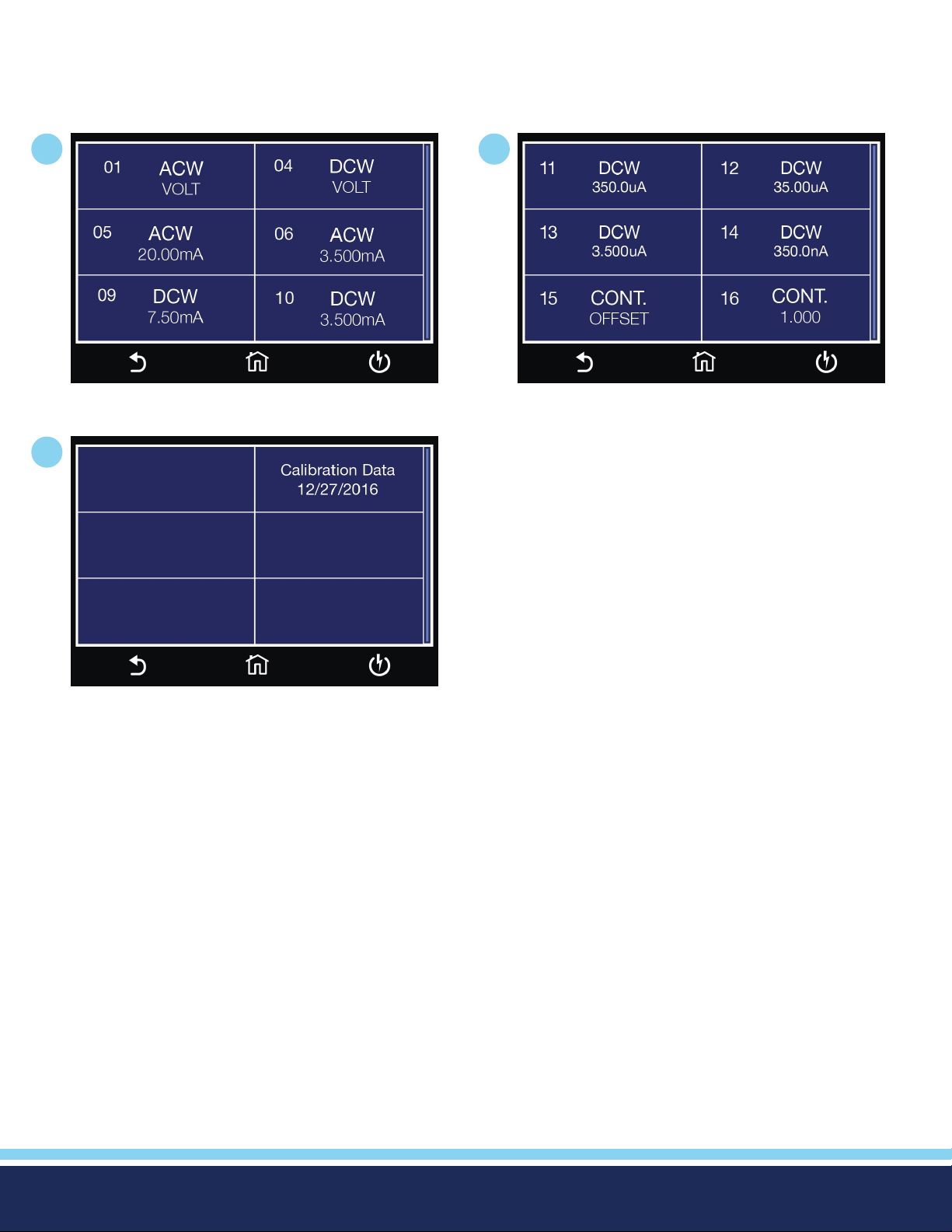
Calibration Initialization
Press and hold the calibration key on the rear panel with a pen, pencil, or small screwdriver while powering ON the Hypot. The
Hypot enters calibration mode after the power on sequence is complete. When the calibration is initialized the calibration screen
will display each calibration point and appear as follows:
1
3
2
From the Calibration screens, use the touchscreen to select the parameter you wish to calibrate. A calibration prompt screen will
now appear that describes the necessary load and connection information for the parameter being calibrated.
Once you press TEST, the Calibration data entry screen will appear for the selected parameter. Read the measurement from your
standard and enter it using the numeric keypad. Once a value is entered the screen for the next step will appear.
© Ikonix USA 2021
96
Page 97
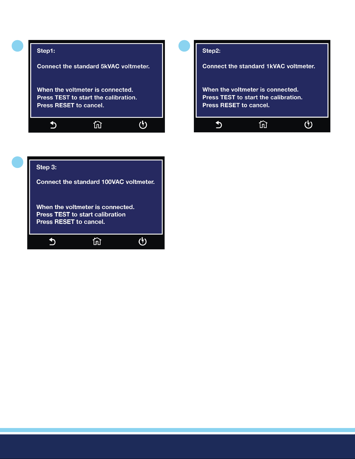
Calibration Examples
Calibration of AC Hipot Voltage
1
Follow on screen instruction to complete Step 1. Follow on screen instruction to complete Step 2.
2
3
Follow on screen instructions to complete Step 3.
© Ikonix USA 2021
97
Page 98
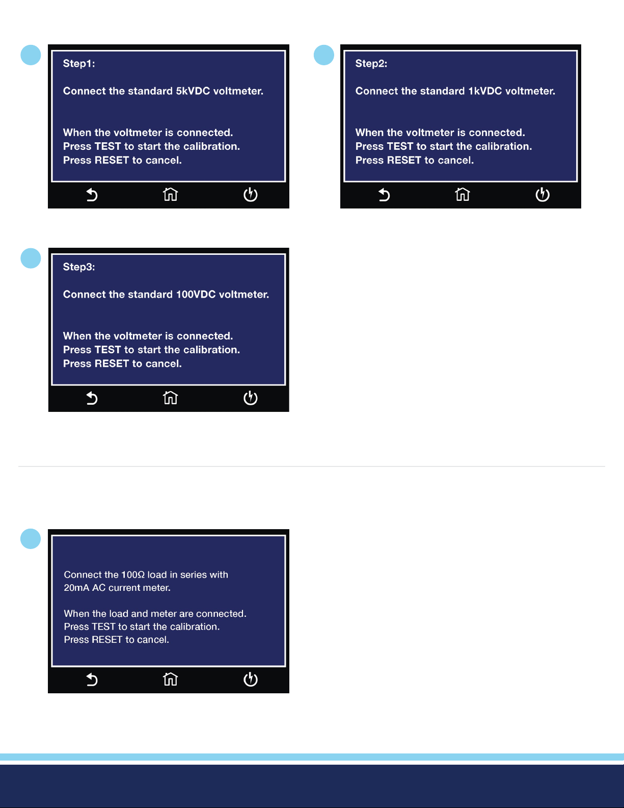
Calibration of DC Hipot Voltage
1
Follow on screen instruction to complete Step 1.
3
2
Follow on screen instruction to complete Step 2.
Follow on screen instruction to complete Step 3.
Calibration of 20mA AC Current Range
1
Follow on screen instruction to complete Step 3.
© Ikonix USA 2021
98
Page 99
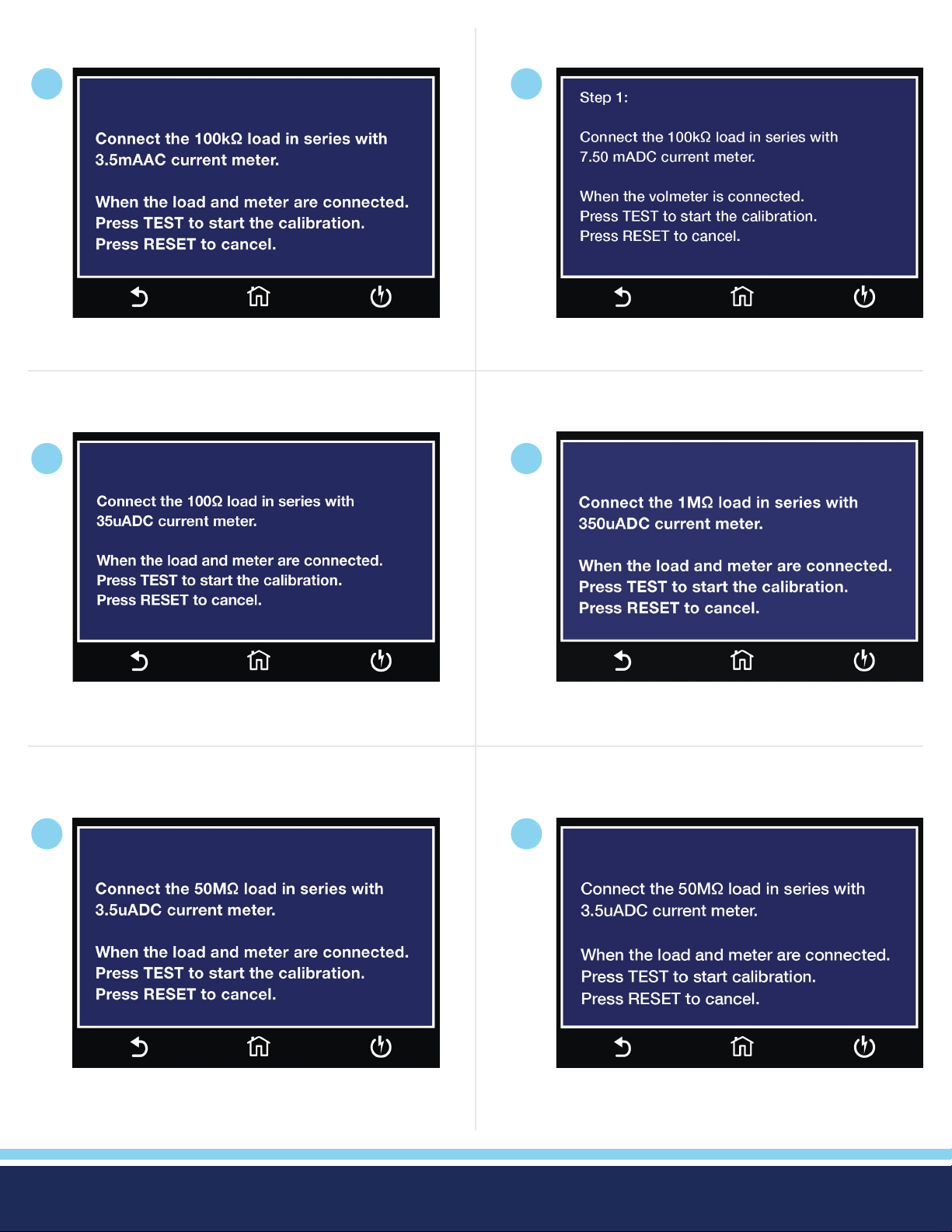
Calibration of 3.5mA AC Current Range
Calibration of 7.50 mA DC Current Range
1
Follow on screen instruction to complete this step.
Calibration of 3.5uA DC Current Range
1
1
Follow on screen instruction to complete this step.
Calibration of 3.500mA DC Current Range
1
Follow on screen instruction to complete this step.
Calibration of 35uA DC Current Range
1
Follow on screen instruction to complete this step.
Follow on screen instruction to complete this step.
Calibration of 3.5uA DC Current Range
1
Follow on screen instruction to complete this step.
© Ikonix USA 2021
99
Page 100
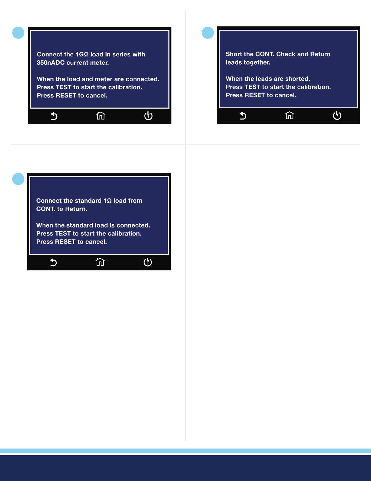
Calibration of 350nA DC Current Range
Calibration of DC Continuity Offset
1
Follow on screen instruction to complete this step.
Calibration of DC Continuity 1Ω
1
1
Follow on screen instruction to complete this step.
Follow on screen instruction to complete this step.
© Ikonix USA 2021
100
 Loading...