

Page 1
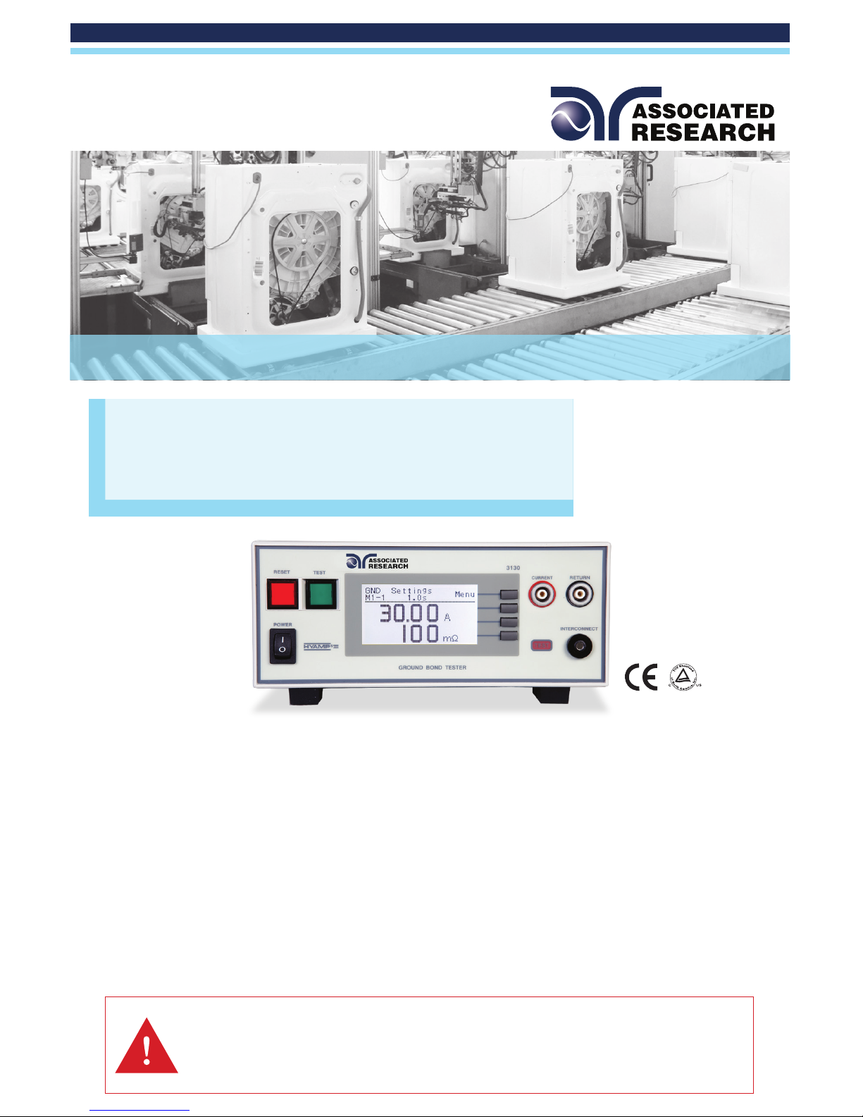
HYAMP® III
Models 3130, 3140, 3145, 3160
SAFETY CHECKLIST
Survey the test station. Make sure it is safe & orderly.
Always keep unqualied/unauthorized personnel away from the test area.
Familiarize yourself with safety protocols in the event of a problem.
Exercise caution and never touch products or connections during a test.
Train operators. Never touch clips directly and always connect the return lead rst.
You should always know when a test is being performed.
WARNING: THIS GUI DE WAS CREATED F OR OPERATORS HAV ING SOME FAMI LIARIT Y WITH ELEC TRICAL SAFET Y
TESTING. AN ELECTRICAL SAFETY TESTER PRODUCES VOLTAGES AND CURRENTS THAT CAN CAUSE HARMFUL
OR FATAL ELECTRIC SHOCK. TO PREVENT ACCIDENTAL INJURY OR DEATH, THESE SAFETY PROCEDURES MUST
BE STRICTLY OBSERVED WHEN HANDLING AND USING A TEST INSTRUMENT. CONTACT US AT
[email protected] FOR MORE INFO ON HOW TO GET TRAINED ON ELECTRICAL SAFETY TESTING.
Quick Start Guide
Page 2
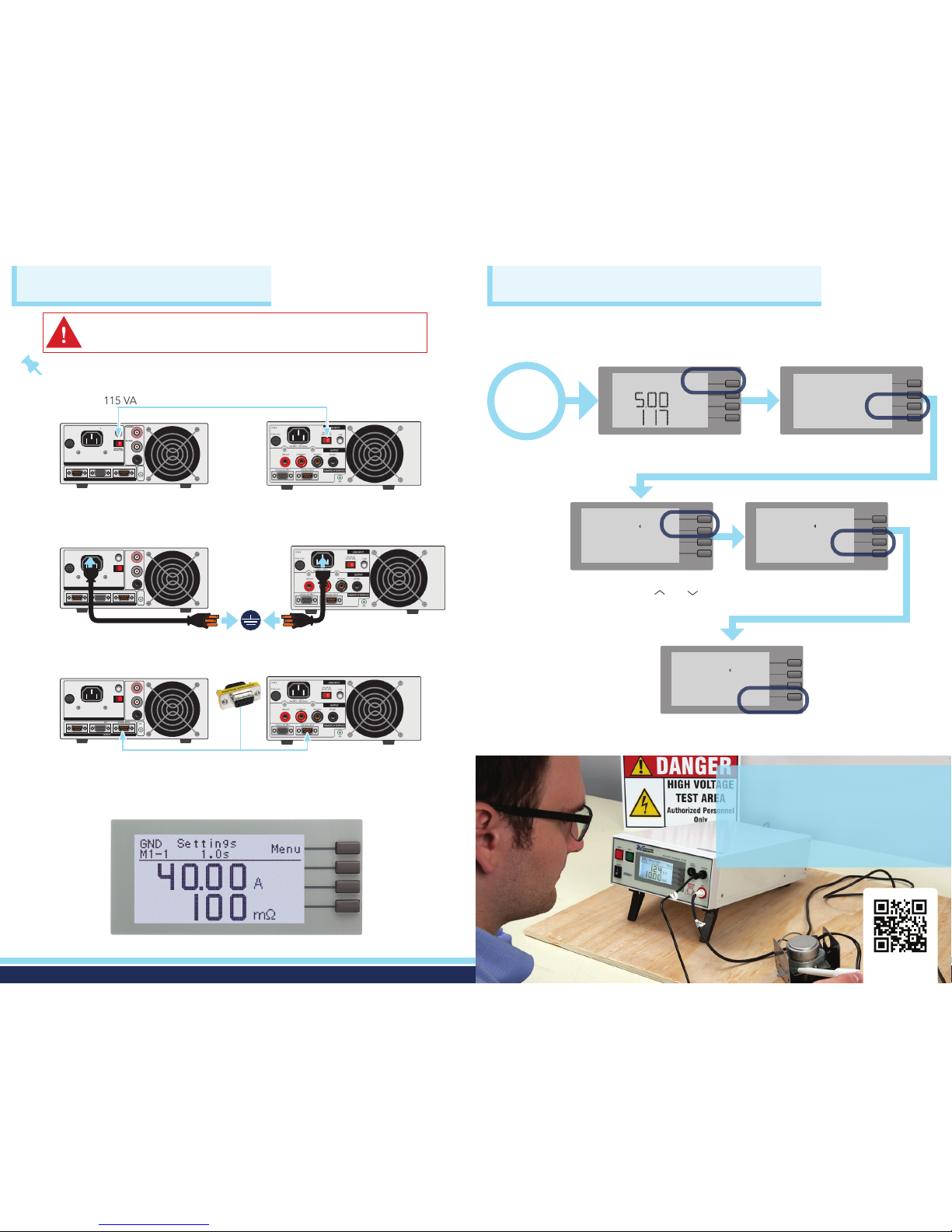
EDIT SYSTEM PARAMETERS
Select the correct input line voltage on the rear panel of the instrument,
either 115 VAC or 230 VAC.
Connect the female end of the power input plug into the rear of the
instrument and plug the male end of the cord into a grounded power source.
Plug the Interlock Disable Key into the signal/input connector on the rear
panel of the instrument.
Turn the POWER switch to ON.
The initialization screen will appear. After three seconds the Perform Test
screen will appear as shown below.
Note: 3160 Owners: Please reference your product manual for rear panel controls.
Congure the instrument system parameters to your preferences. The instrument
system parameters are global and will affect all tests that you perform regardless
of memory location and memory step.
SIGNAL INPUT
CAL
SIGNAL OUTPUTOPTION
CAT.II
T6.3A 250V
VOLTAGE
SELECTOR
INTERCONNECT
RETURN
CURRENT
GND
115V~/ 230V~
6.3A MAX., 50Hz/60Hz
115
REMOTE INTERFACE
LINE INPUT
SIGNAL INPUT
CAL
SIGNAL OUTPUTOPTION
CAT.II
T6.3A 250V
VOLTAGE
SELECTOR
INTERCONNECT
RETURN
CURRENT
GND
115V~/ 230V~
6.3A MAX., 50Hz/60Hz
115
REMOTE INTERFACE
LINE INPUT
SIGNAL INPUT
CAL
SIGNAL OUTPUTOPTION
CAT.II
T6.3A 250V
VOLTAGE
SELECTOR
INTERCONNECT
RETURN
CURRENT
GND
115V~/ 230V~
6.3A MAX., 50Hz/60Hz
115
REMOTE INTERFACE
LINE INPUT
3130
3130
3130
Perform Test Screen
WARNING: LOCATE A SUITABLE TESTING AREA WITH A THREE-PRONG, GROUNDED
OUTLET. BE SURE THAT YOUR THREE-PRONG OUTLET HAS BEEN TESTED FOR PROPER
WIRING. READ THE SAFETY CHECKLIST OF THIS GUIDE BEFORE STARTING TO TEST.
INSTRUMENT SETUP
3140/3145
3140/3145
3140/3145
START
From the Perform Test screen,
select the MENU soft key twice.
Select the SYSTEM soft key.
Select the “+” soft key to change
the parameter.
GND Settings
M1-1 1.0s
____________________________
Menu
A
mÍ
M1-1 GND
Settings
________________
5.00A
117mÍ
0mÍ
1.0s
Results
Test
System
Exit
PLC Remote OFF
Single Step ON
Alarm 5
Contrast 1
Results Last
Lock OFF
Mem Lock ON
<More>
+
Exit
>
>
PLC Remote OFF
Single Step ON
Alarm 5
Contrast 1
Results Last
Lock OFF
Mem Lock ON
<More>
+
Exit
>
>
Select a parameter to edit by
scrolling with the and
soft keys.
Select EXIT twice to save changes
and return to the Perform Test screen.
PLC Remote OFF
Single Step ON
Alarm 6
Contrast 1
Results Last
Lock OFF
Mem Lock ON
<More>
+
Exit
>
>
To Grounded
Power Source
2 3
With our PPE Safe
Workstation Packages
KEEP YOUR
OPERATOR SAFE
Scan for d etails
Page 3
POWER
TESTRESET
3140
GROUND BOND TESTER
SENSE+
CURRENT RETURN
SENSE-
TEST
POWER
TESTRESET
3130
GROUND BOND TESTER
CURRENT
INTERCONNECT
RETURN
TEST
TEST CONNECTIONCHANGE TEST SETTINGS
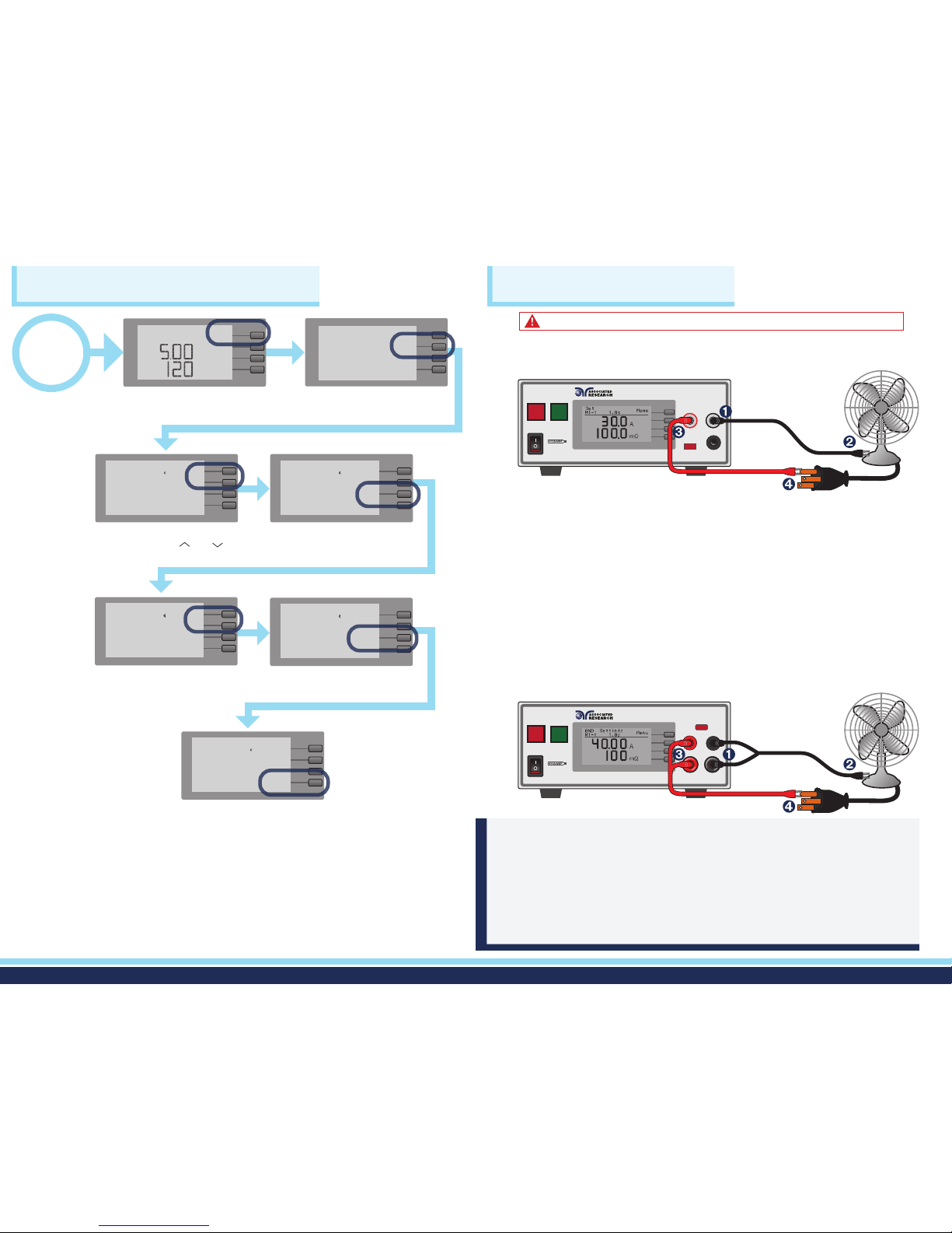
Setting up a test connection on the HYAMP III is straightforward, but differs
slightly by model.
3140/3145/3160 Set Up
3130 Set Up
Connect the black return test lead to the black Return terminal located on
the front panel of the instrument.
For 3140/3145/3160 models connect the sense lead to the Sense(-)
terminal located just above the return terminal.
Clip the end of the black return test lead to the chassis ground of
the DUT.
Connect the red high current test lead to the red Current terminal on the
front panel of the instrument.
For 3140/3145/3160 models connect the sense lead to the Sense(+)
terminal.
Connect the end of the red high current test lead clip to the ground/earth
contact of the DUT.
Push the provided current and return test leads into their mating terminal until
seated against the rubber grommet. Avoid excessive force in seating. If the
grommet becomes compressed, the lock feature may not activate. To release the
lock and remove the leads, push the lead in toward the instrument and then pull
back on the lead to fully remove lead.
DID YOU KNOW?
Always connect the ground return clip rst and double check that both clips
have a solid connection to the DUT.
START
From the Perform Test screen,
select the MENU soft key twice.
On the Test Settings screen,
select the TEST soft key.
Select EDIT once you have
chosen the correct parameter.
Use the + or - soft keys to adjust
the parameter value.
GND Settings
M1-1 1.0s
____________________________
Menu
A
mÍ
M1-1 GND
Settings
________________
5.00A
120mÍ
0mÍ
1.0s
Results
Test
System
Exit
Current 5.00A
Max Lmt 120mÍ
Min Lmt 0mÍ
Dwell 1.0s
Frequency 60Hz
Offset 0mÍ
Connect OFF
Edit
Exit
>
>
Current 5.00A
Max Lmt 120mÍ
Min Lmt 0mÍ
Dwell 1.0s
Frequency 60Hz
Offset 0mÍ
Connect OFF
Edit
Exit
>
>
Current 5.00A
Max Lmt 120mÍ
Min Lmt 0mÍ
Dwell 1.0s
Frequency 60Hz
Offset 0mÍ
Connect OFF
+
-
Edit
Exit
Select a parameter to edit by
scrolling with the and
soft keys.
Current 5.00A
Max Lmt 120mÍ
Min Lmt 0mÍ
Dwell 1.0s
Frequency 60Hz
Offset 0mÍ
Connect OFF
+
-
Edit
Exit
Select ENTER to save your test
settings.
Select EXIT twice to return to the
Perform Test screen.
Current 5.00A
Max Lmt 120mÍ
Min Lmt 0mÍ
Dwell 1.0s
Frequency 60Hz
Offset 0mÍ
Connect OFF
+
-
Enter
Esc
WARNING: DO NOT TOUCH THE DEVICE UNDER TEST ONCE YOU START THE TEST.
4 5
Page 4
SIGNAL INPUT
CAL
SIGNAL OUTPUTOPTION
CAT.II
T6.3A 250V
VOLTAGE
SELECTOR
INTERCONNECT
RETURN
CURRENT
GND
115V~/ 230V~
6.3A MAX., 50Hz/60Hz
115
REMOTE INTERFACE
LINE INPUT
HYPOT®III INTERCONNECTION
SIGNAL INPUT
CAL
SIGNAL OUTPUT
CAT.II
T10A 250V
SENSE+ CURRENT RETURN SENSE-
VOLTAGE
SELECTOR
GND
115V~/ 230V~
10A MAX., 50Hz/60Hz
115
LINE INPUT
OUTPUT
REMOTE INTERFACE
SIGNAL INPUT
CAL
SIGNAL OUTPUTOPTION
CAT.II
T6.3A 250V
VOLTAGE
SELECTOR
INTERCONNECT
RETURN
CURRENT
GND
115V~/ 230V~
6.3A MAX., 50Hz/60Hz
115
REMOTE INTERFACE
LINE INPUT
SIGNAL INPUT
CAL
SIGNAL OUTPUT
CAT.II
T3.15A
250V
VOLTAGE
SELECTOR
LINE INPUT
RS232
GND
115V~/ 230V~
3.15A MAX.,
50Hz/60Hz
115
REMOTE INTERFACE
H.V.
RETURN
CONT.
CHECK
CAUTION
CAUTION
HIGH VOLTAGE
RISK OF ELECTRICAL SHOCK. DO NOT REMOVE COVER.
REFER SERVICE TO MANUFACTURER’S SERVICE CENTER.
FOR CONTINUED PROTECTION AGAINST FIRE. REPLACE ONLY
WITH 250V FUSE OF THE SPECIFIED CURRENT RATING.
CAUTION
HIGH VOLTAGE
5KVAC MAX.
6KVDC MAX.
NL
INTERLOCK
DISABLE
INTERLOCK
DISABLE
SIGNAL INPUT
CAL
SIGNAL OUTPUT
CAT.II
T3.15A
250V
VOLTAGE
SELECTOR
LINE INPUT
RS232
GND
115V~/ 230V~
3.15A MAX.,
50Hz/60Hz
115
REMOTE INTERFACE
H.V.
RETURN
CONT.
CHECK
CAUTION
CAUTION
HIGH VOLTAGE
RISK OF ELECTRICAL SHOCK. DO NOT REMOVE COVER.
REFER SERVICE TO MANUFACTURER’S SERVICE CENTER.
FOR CONTINUED PROTECTION AGAINST FIRE. REPLACE ONLY
WITH 250V FUSE OF THE SPECIFIED CURRENT RATING.
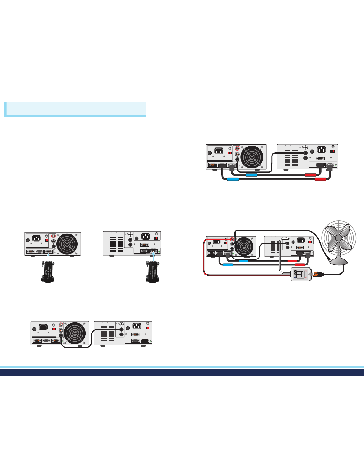
You can interconnect a HYAMP III to all Hypot III models to form a complete test
system. This guide illustrates the 3130 below. Please refer to specic product
manual for exact connections on 3140/3145/3160 models.
Activate the PLC REMOTE on the Hypot III.
Select MENU twice from the Perform Test screen on the Hypot III.
Select SYSTEM then select PLC REMOTE.
Use the + and - soft keys to turn the PLC REMOTE setting to ON.
Select EXIT to return to the Perform Test screen.
INTERCONNECTION OF HYAMP III TO HYPOT III AND CONNECTION
TO A DEVICE UNDER TEST
Plug double sided interlocks (P/N 38142) into the signal inputs of both
instruments.
Using the rear panel connections, connect the following cord:
• P/N HS-8-11 - Plug one end into the Interconnect terminal on the HYAMP
III Ground Bond tester. Plug the other end into the Return terminal on
the rear panel of the Hypot III.
Using the rear panel connections, connect the following cords:
• P/N 5030DT-21 - Plug the blue coded end into the Ground Bond interlock
connector. Plug the red coded end into Hipot signal output.
• P/N 5030DT-22 - Plug the blue coded end into the Ground Bond signal
output. Plug the red coded end into the Hipot interlock connector.
• P/N 05002D-37 - Plug the black return test lead into the rear panel Return
terminal on the 3130. Next, clip the end of the test lead to chassis ground
of the DUT.
• P/N 036541 - Plug the high current lead of the adapter box into the rear panel
Current terminal on the 3130. Plug the white Alden plug into the rear panel
High Voltage terminal on the Hipot tester.
Plug the DUT line cord into the adapter box.
Once the test parameters are set, start the test from the 3130.
If the Ground Bond test passes, the Hipot test will automatically start. If a
test fails, the test sequence will abort and failure results are displayed.
HYAMP 3130
HYAMP 3130
HYAMP 3130
HYAMP 3130
HYPOT III
HYPOT III
HYPOT III
HYPOT III
SIGNAL INPUT
CAL
SIGNAL OUTPUTOPTION
CAT.II
T6.3A 250V
VOLTAGE
SELECTOR
INTERCONNECT
RETURN
CURRENT
GND
115V~/ 230V~
6.3A MAX., 50Hz/60Hz
115
REMOTE INTERFACE
LINE INPUT
SIGNAL INPUT
CAL
SIGNAL OUTPUT
CAT.II
T3.15A
250V
VOLTAGE
SELECTOR
LINE INPUT
RS232
GND
115V~/ 230V~
3.15A MAX.,
50Hz/60Hz
115
REMOTE INTERFACE
H.V.
RETURN
CONT.
CHECK
CAUTION
CAUTION
HIGH VOLTAGE
RISK OF ELECTRICAL SHOCK. DO NOT REMOVE COVER.
REFER SERVICE TO MANUFACTURER’S SERVICE CENTER.
FOR CONTINUED PROTECTION AGAINST FIRE. REPLACE ONLY
WITH 250V FUSE OF THE SPECIFIED CURRENT RATING.
INTERLOCK DISABLE
SIGNAL INPUT
CAL
SIGNAL OUTPUTOPTION
CAT.II
T6.3A 250V
VOLTAGE
SELECTOR
INTERCONNECT
RETURN
CURRENT
GND
115V~/ 230V~
6.3A MAX., 50Hz/60Hz
115
REMOTE INTERFACE
LINE INPUT
SIGNAL INPUT
CAL
SIGNAL OUTPUT
CAT.II
T3.15A
250V
VOLTAGE
SELECTOR
LINE INPUT
RS232
GND
115V~/ 230V~
3.15A MAX.,
50Hz/60Hz
115
REMOTE INTERFACE
H.V.
RETURN
CONT.
CHECK
CAUTION
CAUTION
HIGH VOLTAGE
RISK OF ELECTRICAL SHOCK. DO NOT REMOVE COVER.
REFER SERVICE TO MANUFACTURER’S SERVICE CENTER.
FOR CONTINUED PROTECTION AGAINST FIRE. REPLACE ONLY
WITH 250V FUSE OF THE SPECIFIED CURRENT RATING.
INTERLOCK
DISABLE
INTERLOCK
DISABLE
6 7
Page 5
Safety Is Our Only Focus
®
SCAN FOR
QUICK
START
VIDEO
For additional information about these and other key features of the HYAMP® III, please consult the
full Operation and Service Manual or call us toll-free 1-800-858-TEST (8378) or +1-847-367-4077
©2017 Associated Research • arisafety.com
1/2 017
FOLLOW US!
 Loading...