

Page 1

MODEL 6036B-24
This manual contains important safety and operating instructions for the battery tester you have purchased. You may need to refer to these instructions at a later date.
The electrolyte in automotive batteries is sulfuric acid, which is capable of causing severe damage to skin, eyes, and clothing. When contact with battery acid occurs, proceed as follows:
Eyes: Force open and flood with cool running water at least for 10 minutes, then obtain medical attention immediately. Never use eyes drops or other medication before seeing a doctor.
While batteries are being charged or tested, an explosive gas mixture forms inside each cell. Some of this gas can escape through the vent holes in the filler caps and may remain around the battery in an explosive
condition. Sparks or flames igniting this gas mixture will burn back through the vent hole and explode inside the battery cell. Such an explosion is dangerous not only because of its own force, but also because of the acid
Add distilled water in each cell until battery acid reaches level specified by battery manufacturer. This helps purge excessive gas from cells. Do not over-fill. For a battery without cell caps, carefully follow
WORKING IN VICINITY OF LEAD-ACID BATTERY IS DANGEROUS. BATTERIES GENERATE EXPLOSIVE GASES DURING NORMAL BATTERY OPERATION. FOR THIS REASON IT IS OF
To reduce the risk of battery explosions, follow these instructions and those published by the battery manufacturer and the manufacturer of any equipment you intend to use in the vicinity of the battery. Review
Do not break live electrical circuits at the terminals of batteries because a spark may occur at that point causing an explosion. Always turn battery chargers or tester
For acid contact on skin or clothing, remove clothing and wash skin immediately with soap and water. For acid in eye, immediately flood eye with running cold water for at least 10 minutes and obtain medical
Be extra cautious to reduce risk of dropping a metal tool onto a battery. The tool may spark or short-circuit the battery or other electrical parts which may cause an explosion.
Remove personal metal items such as rings, bracelets, necklaces, and watches when working with a lead-acid battery. A lead-acid battery can produce a short-circuit current high enough to instantly weld a ring
BATTERY TESTER
ASSOCIATED
OPERATOR’S MANUAL
IMPORTANT SAFETY INSTRUCTIONS
SAVE THESE INSTRUCTIONS
CAUTION:
a)
Remove contaminated clothing and flood skin for at least 10 minutes with clear, cool water.
b)
electrolyte which would spray onto anything in the vicinity.
TO PREVENT EXPLOSIONS:
Use well ventilated areas for charging and testing batteries.
a)
b)
manufacturer’s instructions.
Allow no smoking, sparks or open flames near batteries being charged, tested or batteries recently charged and to be tested.
c)
WARNING - RISK OF EXPLOSIVE GASES.
a)
UTMOST IMPORTANCE TO READ THIS MANUAL AND FOLLOW THE INSTRUCTIONS EXACTLY EACH TIME YOU USE THIS BATTERY TESTER.
b)
cautionary marking on these products and on the engine.
c)
the clamps from the battery terminals.
PERSONAL PRECAUTIONS:
a) Wear complete protection and avoid touching eyes while working near battery.
b)
attention immediately. Never use eye drops or other medication before seeing a doctor.
NEVER smoke or allow a spark or flame in the vicinity of battery or engine.
c)
d)
e)
or the like to metal, and cause severe burn.
f) Spilled acid: Neutralize with a solution of baking soda ( 1 pound per gallon of cold water ) or household ammonia (1 pint per gallon of cold water)
1
Page 2
UNPACKING AND UNLOCKING THE UNIT
Connect and disconnect DC output clamps only after setting fan switch to “Automatic” position, and the LOAD CONTROL knob is counter-clockwise (CCW.) as far as possible. (Don’t force knob).
When attaching clamps to battery posts, twist or rock clamp back and forth several times to make a good connection. This tends to prevent the clamps from slipping off of the terminals and helps reduce risk of
Either when receiving the unit new or when the unit has been sitting around awhile. The carbon stacks in the unit will collect moisture from the air and will need to be evaporated out. To do this, the unit will
need to be pre-loaded, by turning the knob to a 100 amps and holding the knob for 5 to 10 seconds and releasing the knob (Do this on a good battery that you are not testing). This releases any water that
If a lot of water or steam come out of the unit, do this a few more times to get most of the moisture
Visually inspect batteries for obvious damage. Do not test a battery if the posts are loose, the case is cracked or the fluid level is below the top of the plates. With “maintenance free” batteries, see manufacturer’s
Depress FAN switch to “Automatic” and the fan will automatically turn on as the LOAD CONTROL on top of tester is turned clockwise, and automatically go to off as the LOAD CONTROL is turned counter-
1. To remove the unit from the carton, grasp the side handles in the packing and pull both the packing and the unit out of the carton.
Remove the internal packing from the unit and return it to the carton. Set the carton and internal packing aside for future use.
2. Hold onto the knob to keep the shaft from spinning after it is unlocked. Loosen the set screw in the locking collar with the 3/32 hex
wrench provided. DO NOT remove the set screw from the locking collar. Allow the shaft to back out slowly until it stops.
(Locking down the carbon stack helps to prevent the carbon disk and ceramic tubes from breaking during shipping, or anytime the
unit needs to be transported.)
NOTE:
When shipping or transporting the unit, be sure to lock the shaft down by turning the knob all the way down and tightening
the the locking collar set screw with the 3/32 hex wrench provided.
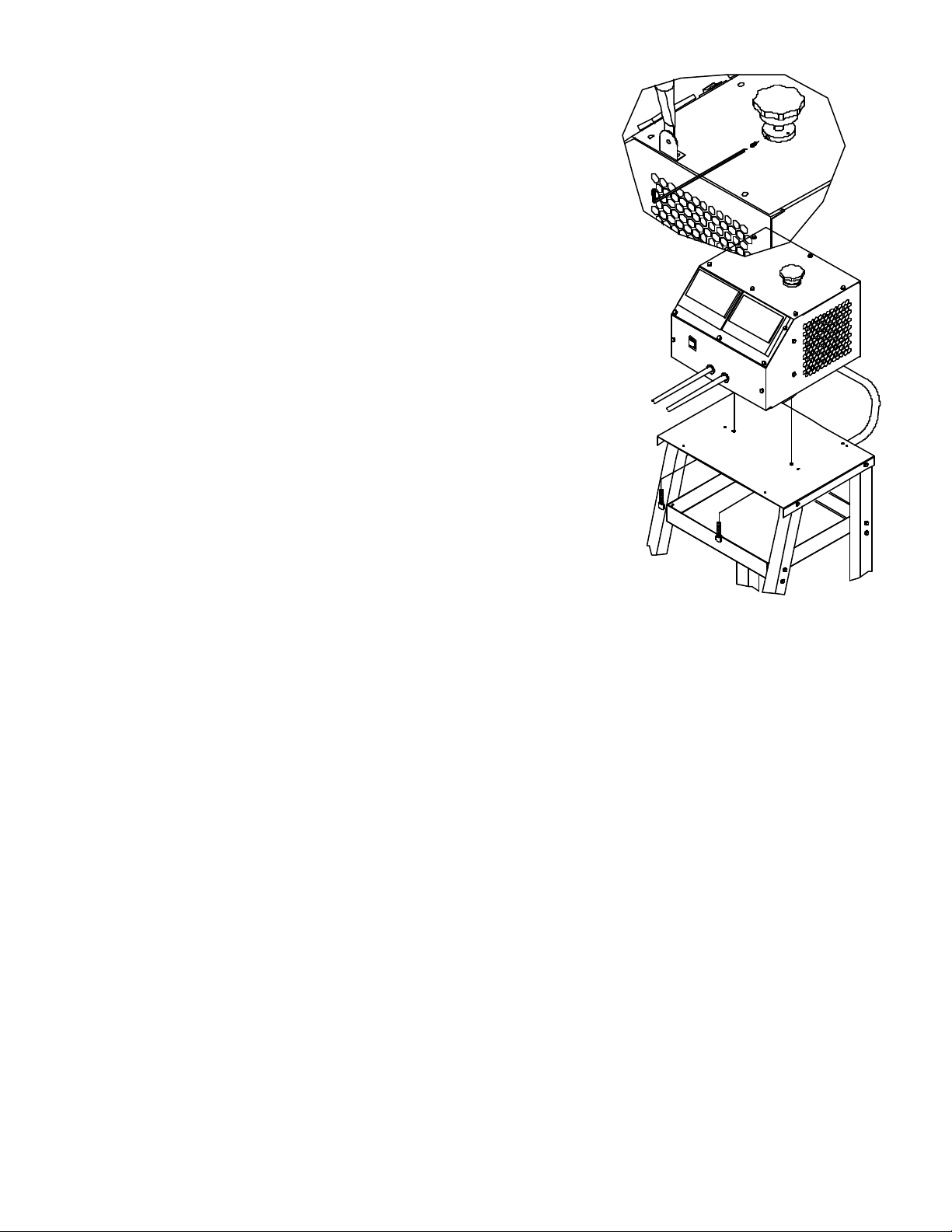
ATTACHING THE 6036B TO OPTIONAL 6038 UTILITY CART
If you have also purchased the optional two wheel utility cart model 6038, the two pieces are assembled as follows.
1. Set the 6036B on top of the cart with the front of the unit facing away from the handle. Align the two holes in the mounting plate with the
threaded inserts in the bottom of the tester.
2. Insert the spade bolt through the hole in the mounting plate and thread the spade bolt into the insert as shown.
PREPARING TO TEST
a) When it is necessary to remove the battery from the vehicle for testing, always remove the ground terminal first. Make sure all accessories
in the vehicle are turned off, so as not to cause an arc.
b) Clean battery terminals. Be careful to keep corrosion from coming in contact with eyes.
c) Determine the cold cranking amps (CCA) rating of battery by referring to the car owner’s manual or label on the battery.
TESTER LOCATION
a) Locate tester as far away from the battery as DC cables permit.
b) Never allow battery acid to drip on tester or other items when handling a hydrometer, reading specific gravity or filling a battery.
c) Do not set a battery on top of the tester.
d) Position cables to reduce risk of danger by hood, door or moving engine parts.
e) Stay clear of fan blades, belts, pulleys, and other parts that can cause personal injuries.
f) Do not block air passaging through the tester.
CONNECTIONS AND PRECAUTIONS
a)
b)
sparking.
NOTE:
might be in the carbon stacks and prevents the carbons from cracking during normal operation. Note:
out.
OPERATING INSTRUCTIONS
1.
instructions for checking water level. Do not test a frozen battery.
2. Be sure Voltmeter and Ammeter pointers are zeroed. Zero meters by adjusting screw on face of meter until meter points to zero.
3. See connection precautions before connecting or disconnecting clamp prior to test.
4.
clockwise.
5. Connect RED clamp to POSITIVE (POS, +, P) battery post and BLACK clamp to NEGATIVE (NEG, -, N) battery post.
2
Page 3

CAUTION:
DO NOT CONNECT OR DISCONNECT FROM BATTERY WHILE FAN
. To safely remove clamps depress the FAN switch to “Automatic” and turn LOAD CONTROL KNOB counter-clockwise as far as
Adjust LOAD CONTROL knob clockwise (CW) to 100 amps for 3 seconds. Adjust LOAD CONTROL knob counter-clockwise until the meter reads zero. Read Voltmeter.
Adjust “LOAD CONTROL” knob to the one-half of the battery’s cold cranking amperage (CCA) rating using AMPERES LOAD meter as a reference. Hold this reading. During this 15 seconds interval the
amperage will probably change due to resistance changes in the cables, carbons and the battery. Readjust the LOAD CONTROL during this 15 seconds interval to maintain the amp figure required. At the end
of 15 seconds and with the load on, read the battery’s voltage on the volt scale. TURN THE LOAD CONTROL KNOB COUNTER-CLOCKWISE AS FAR AS POSSIBLE. (OFF) SEE CAUTION ABOVE
The voltage reading obtained from a battery changes in relation to the temperature of the battery and also in relation to the amperage being drawn from the battery. The “Battery Temperature Compensation”
that should be obtained for the test procedure given. i.e.: The outside temperature is 60 degrees F. From chart note that the minimum volts for a
good battery is 9.5 at 60 degrees F. When at the end of the 15 second test you find that the battery’s voltage is equal to or greater than 9.5, the battery is good. When the voltage is 9.4 or less the battery is
To determine if a battery is adequate for an application, a stress test may be applied to a battery. Determine the maximum current draw, minimum acceptable voltage, and maximum cranking time of the vehicle in
Be sure that the battery in the car tests good. Start engine with tester connected to the battery. The charging voltage of the alternator should allow the pointer to fall in the green
zone. If the pointer is in the red zone to the left of the green zone, the voltage is too low to fully charge the battery. If the pointer is in the red zone to the right of the green zone, the voltage is too high and may damage
Connect tester to battery. Be sure battery is fully charged. Ground the ignition, by removing the coil cable from the distributor cap. Ground the cable to the engine block with a
jumper wire to prevent arcing of high-voltage spark that could cause a fire, someone getting shocked, or damage to the ignition system. (On GM car with HEI ignition, simply disconnect the small lead connected to the
BAT. terminal on the distributor.) Turn ignition switch on and allow starter to run for 5 seconds. Read the voltage on the VOLT scale while cranking. With car circuit off and with the tester connected to the battery
terminals, adjust LOAD CONTROL knob to set the VOLTMETER reading to be the same as measured while cranking the engine. Read Amps on ammeter and the reading is the starting current of the car.
A static charge may build-up on the meter face, causing the needle to be off zero. For the meter to read correctly, this charge must be neutralized. Spray “Static Guard” or equivalent on the meter or wipe
WHEN TESTING 24V BATTERIES AT CURRENTS GREATER THAN 500 AMPS, YOU MUST USE THE MANUAL FAN SETTING AND ALLOW THE
CARBON PILE ASSEMBLY TO COOL FOR 3 MINUTES OR LONGER AFTER EACH TEST. FAILURE TO OBSERVE THIS CAUTION WILL RESULT
IN SHORTENED LIFE OR SERIOUS DAMAGE TO THE CARBON PILE DUE TO THE GREATER HEAT GENERATED WHILE TESTING LARGE 24V
BATTERIES.
NOTE: Depress FAN switch to “Manual” and the fan will run for as long as the tester is connected to a battery.
IS RUNNING, OR SWITCH IS IN “MANUAL” POSITION
possible. Fan will automatically be OFF and then the clamps may safely be removed from battery.
6. DETERMINE STATE OF CHARGE OF BATTERY
a)
Results:
b)
1. Pointer in green zone - proceed to LOAD TEST.
2. Pointer in red zone to left of green zone - battery is tool low to test. Recharge & repeat procedure.
Green band indicates a battery that is at least 75% charged.
c)
BATTERY TEMPERATURE COMPENSATION 15 SECOND LOAD TEST MINIMUM VOLTS
°C 21 16 10 4 -1 -7 -12 -18
°F 70 60 50 40 30 20 10 0
6V BATTERY 4.8 4.75 4.7 4.65 4.55 4.45 4.35 4.25
12V BATTERY 9.6 9.5 9.4 9.3 9.1 8.9 8.7 8.5
24V BATTERY 19.2 19.0 18.8 18.6 18.2 17.8 17.4 17.0
LOAD TEST
7.
a) Figure the value of one-half of Cold Cranking Amps (CCA) rating of battery to be tested.
b)
WHEN TESTING 24V BATTERIES.
c)
given here and on the face of the tester gives the minimum voltage
defective.
When smoke is emitted from any cell of the battery, the battery is defective regardless of the test indications
8. STRESS TEST:
a)
which the battery is to be installed.
b) Run a load test at the determined current and time and check that the battery voltage is above the minimum required.
APPLICATION DATA:
ALTERNATOR TEST:
the battery. NOTE: In very cold weather, the alternator may read above the green zone. Check owner’s service manual.
STARTER CURRENT TEST:
VOLTMETER: The tester may be used as a voltmeter to troubleshoot electrical problems on any 6, 12, or 24 volt vehicle. Read voltages on volt scale.
NOTE:
with a cloth dampened with soap and water.
WIRING DIAGRAM
3
Page 4

REPL
ACEMENT PARTS
AMMETER
VOLTMETER
SHUNT ASSEMBLY
BRACKET & NUT ASSY.
TOP PLATE ASSY.
CARBON STACK W/CERAMIC TUBE
CERAMIC TUBES
CIRCUIT BOARD
FAN RESISTOR
Parts may be purchased from your local authorized service depot listed in the Service Procedure Manual supplied with your
products.
If you elect to order parts from the factory, you may do so by mail or by phone. The minimum order from the factory is $25.00. Orders
received that are under the minimum will not be processed. Taxes and freight are extra and are not considered to be part of the
dollar value of the order. We DO NOT have a C.O.D. policy. Casher checks, Money order, Master Card, or Visa are acceptable. If you
use a Master or Visa Card, send only the number an the expiration date. DO NOT SEND THE CARD.
X2303 Rev. 6/98 027-0446
...........................................................................
.........................................................................
....................................................................
.................................................................
.....................................................................
........................................................
......................................................................
.......................................................................
.......................................................................
ASSOCIATED EQUIPMENT CORPORATION
5110 Brown Avenue St. Louis, Missouri 63115
(314) 385-5178
610333
610565
610335
610337
610338
610889
610872
610567
610566
FIG. PLT. FILE NAME DESCRIPTION
1 LOGO.EPS LOGO
2 27293-2.PLT LOCK-DOWN
3 27293-3.plt assembly view of tester to cart
4 B3287.PLT WIRING DIAGRAM
4
 Loading...