

Page 1

MODEL 6021
OPERATOR'S MANUAL
ASSOCIATE
IMPORTANT SAFETY INSTRUCTIONS
D
1. SAVE THESE INSTRUCTIONS. This manual contains important safety and operating instructions for battery
charger/tester you have purchased. You may need to refer to these instructions at a later date.
CAUTION. To reduce risk of injury, charge only wet cell, lead-acid, automotive type rechargeable batteries. Other types of batteries may
2.
burst causing personal injury and property damage.
3. Do not expose the charger to rain or snow if specifically warned on the unit not to do so.
4. Use of an attachment not recommended or sold by the battery charger manufacturer may result in a risk of fire, electric shock, or injury to
persons.
5. To reduce the risk of damage to the electric plug and cord, pull by the plug rather than the cord when disconnecting the charger.
6. Make sure the cord is located so that it will not be stepped on, tripped over, or otherwise subjected to damage or stress.
7. An extension cord should not be used unless absolutely necessary. Use of a improper extension cord could result in a risk of fire and electric
shock. If an extension cord must be used, make sure:
a. That the pins on the plug of extension cord are the same number, size, and shape as those of the plug on the charger;
b. That the extension cord is properly wired and in good condition; and
c. If the length of the extension cord is less than 25 feet, use a 16AWG cord, If 50 feet- 12AWG, 100 feet-10AWG, 150 feet-8AWG.
8. Do not operate the charger with a damaged cord or plug, replace them immediately.
9. Do not operate the charger if it has received a sharp blow, been dropped, or otherwise damaged in any way; take it to a qualified serviceman.
10. Do not disassemble the charger; take it to a qualified serviceman when service or repair is required. Incorrect reassembly may result in risk of
electric shock or fire.
11. To reduce the risk of electric shock, unplug the charger form the outlet before attempting any maintenance or cleaning. Turning off the controls
will not reduce this risk.
WARNING - RISK OF EXPLOSIVE GASES
12.
a. WORKING IN VICINITY OF A LEAD-ACID BATTERY IS DANGEROUS. BATTERIES GENERATE EXPLOSIVE GASES DURING
NORMAL BATTERY OPERATION. FOR THIS REASON IT IS OF UTMOST IMPORTANCE THAT EACH TIME BEFORE USING YOUR
CHARGER, YOU READ THIS MANUAL AND FOLLOW THE INSTRUCTIONS EXACTLY.
b. To reduce the risk of battery explosion, follow these instructions and those published by the battery manufacturer and manufacturer of any
equipment you intend to use in vicinity of the battery. Review cautionary markings on these products and on the engine.
PERSONAL PRECAUTIONS
13.
a. Someone should be within range of your voice or close enough to come to your aid when you work near a lead-acid battery.
b. Have plenty of fresh water and soap nearby in case battery acid contacts skin, clothing, or eyes.
c. Wear complete eye protection, and clothing protection. Avoid touching eyes while working near battery.
d. If battery acid contacts skin or clothing, wash immediately with soap and water. If acid enter eyes, immediately flood eyes with running cold
water for at least 10 minutes and get medical attention immediately.
e. NEVER smoke or allow a spark or flame in vicinity of the battery or engine.
f. Be extra cautious to reduce risk of dropping a metal tool onto the battery. It might spark or short circuit the battery or other electrical parts
that may cause an explosion.
g. Remove personal metal items such as rings, bracelets, necklaces, and watches when working with a lead-acid battery. A lead-acid battery
can produce a short circuit current high enough to weld a ring or the like to metal, causing a severe burn.
h. Use this charger for charging a LEAD-ACID battery only. It is not intended to supply power to a low-voltage electrical system other than in
an automotive application. Do not use this battery charger for charging dry-cell batteries that are commonly used with home appliances.
These batteries may burst and cause injury to persons and damage to property.
I. NEVER charge a frozen battery.
PREPARING TO CHARGE
14.
a. If necessary to remove battery from vehicle to charge, always remove the grounded terminal from the battery first. Make sure all
accessories in the vehicle are off, so as not to cause an arc.
b. Be sure the area around the battery is well ventilated while the battery is being charged. Gas can be forcefully blown away by using a
piece of cardboard or other non-metallic material as a fan.
c. Clean the battery terminals. Be careful to keep corrosion from coming in contact with eyes.
d. Add distilled water in each cell until battery acid reaches level specified by the battery manufacturer. This helps purge excessive gas from
cells. Do not overfill. For a battery without cell caps, carefully follow the manufacturer's recharging instructions.
e. Study all battery manufacturer's specific precautions such as removing or not removing the cell caps while charging and the recommended
rates of charge.
f. Determine voltage of the battery by referring to the car owner's manual and make sure that the output voltage selector switch is set at the
correct voltage. If the charger has adjustable charge rate, charge the battery initially at the lowest rate.
1
Page 2
15. CHARGER LOCATION
a. Locate the charger as far away from the battery as the DC cables permit.
b. Never place the charger directly above the battery being charged; gases from the battery will corrode and damage the charger.
c. Never allow battery acid to drop on the charger when reading the specific gravity or filling battery,
d. Do not operate the charger in a closed-in area, or restrict ventilation in any way.
e. Do not set a battery on top of the charger.
DC CONNECTION PRECAUTIONS
16.
a. Connect and disconnect the DC output clamps only after setting the charger switches to the OFF position and removing the AC cord from
the electric outlet. Never allow the clamps to touch each other.
b. Attach the DC clamps to the battery post and twist or rock back and forth several times to make a good connection. This tends to keep the
clamps from slipping off the terminals and helps to reduce the risk of sparking.
FOLLOW THESE STEPS WHEN THE BATTERY IS INSTALLED IN A VEHICLE. A SPARK NEAR THE BATTERY
17.
MAY CAUSE A BATTERY EXPLOSION. TO REDUCE THE RISK OF A SPARK NEAR THE BATTERY:
a. Position the AC and DC cords to reduce the risk of damage by the hood, door, or moving engine parts.
b. Stay clear of fan blades, belts, pulleys, and other parts that can cause injury to persons.
c. Check the polarity of the battery post. The POSITIVE (POS, P, +) battery post usually has a larger diameter than the NEGATIVE (NEG, N,
-) post.
d. Determine which post of the battery is grounded (connected) to the chassis. If the negative post is grounded to the chassis (as in most
vehicles), see item "e". If the positive post is grounded to the chassis, see item "f".
e. For negative-grounded vehicles, connect the POSITIVE (RED) clamp from the battery charger to the POSITIVE (POS, P, +) ungrounded
post of the battery. Connect the NEGATIVE (BLACK) clamp to the vehicle chassis, heavy gauge metal part of the frame, or engine block,
away from the battery. Do not connect to the carburetor, fuel lines, or sheet metal body parts.
f. For positive-grounded vehicles, Connect the NEGATIVE (BLACK) clamp from the battery charger to the NEGATIVE (NEG, N, -)
ungrounded post of the battery. Attach the POSITIVE (RED) clamp to the vehicle chassis or engine block away from the battery. Do not
connect the clamp to the carburetor, fuel lines, or sheet-metal body parts.
g. When disconnecting the charger, turn the switches to OFF, disconnect the AC cord, remove the clamp from the vehicle chassis, and then
remove the clamp from the battery terminal.
h. See the operating instructions for length of charge information.
FOLLOW THESE STEPS WHEN THE BATTERY IS OUTSIDE THE VEHICLE. A SPARK NEAR THE BATTERY
18.
MAY CAUSE BATTERY EXPLOSION. TO REDUCE THE RISK OF A SPARK NEAR THE BATTERY:
a. Check the polarity of the battery post. The POSITIVE (POS, P, +) usually has a larger diameter than the NEGATIVE (NEG, N, -) post.
b. Attach at least a 24 inch long 6-gauge (AWG) insulated battery cable to the NEGATIVE (NEG, N, -) battery post.
c. Connect the POSITIVE (RED) charger clamp to the POSITIVE (POS, P, +) post of the battery.
d. Position yourself and the free end of the cable as far away from the battery as possible, then connect the NEGATIVE (BLACK) charger
clamp to the free end of cable.
e. Do not face the battery when making the final connection.
f. When disconnecting the charger, always do so in reverse sequence of connecting procedure, and break the first connection while standing
as far away from the battery as practical.
g. A marine (boat) battery must be removed and charged on shore. To charge it on board requires equipment specially designed for marine
use.
GROUNDING AND AC POWER CORD CONNECTION INSTRUCTIONS
19.
The charger should be grounded to reduce the risk of electric shock. This charger is equipped with an electric cord having an equipment
grounding conductor and a grounding plug. The plug must be plugged into an outlet that is properly installed and grounded in accordance with
all local codes and ordinances.
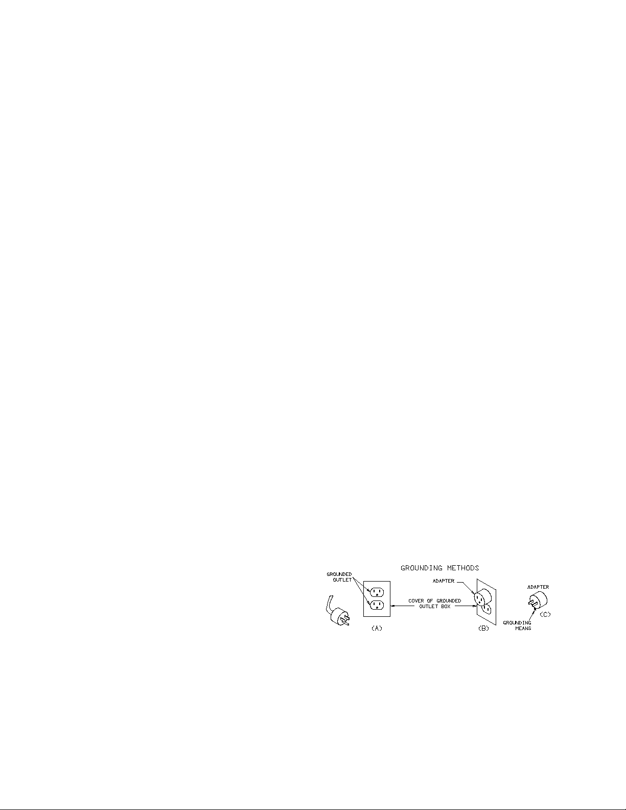
DANGER. Never alter the AC cord or plug provided - if it will not fit the outlet, have a proper outlet installed by a qualified electrician.
Improper connection can result in a risk of an electric shock. This battery charger is for use on a nominal 120-volt circuit, and has a grounding
plug that looks like the plug illustrated in FIGURE (A). A temporary adapter, which looks like the adapter illustrated in FIGURE (C), may be used
to connect this plug to a two-pole receptacle, as shown in FIGURE (B), until a properly grounded outlet can be installed by a qualified
electrician.
DANGER. Before using an adapter as illustrated, be certain
that the center screw of the outlet plate is grounded. The greencolored rigid ear or lug extending from the adapter must be
connected to a properly grounded outlet - make certain it is
grounded. If necessary, replace the original outlet cover plate
screw with a longer screw that will secure the adapter ear or lug
to the outlet cover plate and make ground connection to
grounded outlet.
NOTE: USE OF AN ADAPTER IS NOT ALLOWED IN CANADA. IF A GROUNDING TYPE RECEPTACLE IS NOT AVAILABLE, DO NOT
USE THIS APPLIANCE UNTIL THE PROPER OUTLET IS INSTALLED BY A QUALIFIED ELECTRICIAN.
2
Page 3

20. LENGTH OF CHARGE
a. Test the battery for state of charge. Do not charge if it is over 75% charged or the battery is determined to be defective.
b. Set beginning amps charge rate for size of battery and state of charge per charts
c. Charge for length of time per chart.
d. Discontinue charge when the specific gravity of electrolyte reaches 1.260 or above. A temperature compensating hydrometer should be
used for this reading. Discontinue charge if the battery begins to gas excessively or when the temperature of the electrolyte reaches
approximately 120EF. Do not overcharge batteries. Overcharging results in excessive water loss and eventual damage to the battery.
BATTERY SIZE TABLE
Battery Size Small Medium Large
Ampere Hours 40 60 80+
Reserve Capacity 60 90 100+
Cold Cranking Amps 275 350 400+
STATE OF CHARGE TABLE
State Of Charge 75% 50% 25% DEAD
Specific Gravity 1.225 1.185 1.140 1.110
Open Circuit Voltage 6V 6.2 6.05 5.95 5.9
Open Circuit Voltage 12V 12.4 12.1 11.9 11.8
Open Circuit Voltage 24V 24.8 24.2 23.8 23.6
ASSEMBLY INSTRUCTIONS
21.
1. Remove the four screws from the back of charger and attach the handle in an upright position.
2. Remove the four screws on the bottom toward the front of the charger and attach the leg with the screws
provided.
3. Put one of the axle nut on one side of the axle by tapping the nut on with a hammer. Then slide the axle
through one of the wheels and then through the hole in the charger until it comes out the other end. Put the
other wheel and axle nut on.
Battery Size % Charge
Small 25–50% 30 20 20 15 15 10
Medium 25–50% 45 30 25 20 20 20
Large 25–50% 60 40 35 30 30 30
CHARGE RATE Vs MINUTES CHARGE
0–25% 45 30 30 25 25 20
50–75% 15 10 10 10 5 5
0–25% 70 50 45 40 35 30
50–75% 25 15 15 10 10 10
0–25% 90 55 55 50 45 45
50–75% 30 20 20 15 15 15
MINUTES
15 30 45 60 75 90
A
M
P
E
R
E
S
OPERATING INSTRUCTIONS
22.
CAUTION - This battery charger must be fully assembled before operating. Failure to do so may result in
risk of injury.
TO CHARGE BATTERIES
Make the connections to the battery per the instructions in the previous sections.
Determine if the battery is 6 or 12 volts. Set the CHARGE VOLTAGE switch to 6/12 LO CHARGE for a 6 or 12
volt battery. If higher rate is desired, set at 12 HIGH. DO NOT
low or charge any battery on 12V engine start.(Damage may occur to the battery.) Turn the timer on and the
Ammeter will show the amount of current delivered to the battery. Length of charge should be per the above
chart and instructions.
charge a 6 volt battery at setting other than 6/12
12 VOLT ENGINE START
Turn off all lights and accessories in the stalled vehicle. Connect the charger to battery per previous instructions. Charge the battery on 12 HI for
at least five minutes before attempting to start the vehicle. Put the switch in the 12V ENGINE START position. Start the vehicle with the charger
connected to the battery. Follow the duty cycle on the unit.
NOTE: DO NOT
the vehicle fails to start, while waiting for the starter to cool, allow the charger to continue to charge the battery. Turn the switch to OFF and
remove the AC power cord from the electric outlet before disconnecting the DC clamps.
crank the engine more than 20 seconds in any five minute period; excessive cranking may overheat and damage the starter. If
BATTERY LOAD TEST
This test evaluates the battery's ability to crank an engine. The tester draws current from the battery while measuring its voltage level. The
voltage level of a good battery will remain relatively steady under load, but a defective battery will show a rapid loss in voltage. Battery size
3
Page 4

(CCA rating) and temperature will affect test results - follow instructions carefully.
1. Turn off engine, accessories and battery test equipment.
2. Connect negative (black) clamp to the negative (NEG, N,-) battery post. Connect positive (red) clamp to positive (POS, P, +) battery post.
"Rock" clamps back and forth to insure a good electrical connection.
3. With clamps connected, tester's meter will indicate battery's STATE OF CHARGE. If state of charge is less then 12.4 (6.2) volts ("V"
symbol on meter), the battery should be recharged before load testing. If recharging does not bring voltage to 12.4 (6.2), battery is
defective. If meter needle is off scale to the left, check for loose or reversed clamps; otherwise battery is defective.
4. Note battery's rating in Cold Cranking Amps (CCA). If the rating is not printed on the battery, use the following guidelines to estimate
battery size. Small (4 cyl) -300 CCA; Medium (6 cyl) -400 CCA; Large (8 cyl) -500 CCA.
5. Depress load switch for 10 seconds.
6. Read meter at the end of 10 seconds - with switch depressed. Refer to LOAD TEST ANALYSIS chart.
COMPENSATING FOR LOW TEMPERATURES
Low temperature has a degrading effect on batteries and will affect test results. This can be compensated by reading a different scale.
If battery is 50E, read scale 100 CCA less then battery rating.
If battery is 30E, read scale 200 CCA less than battery rating.
If battery is 10E, read scale 300 CCA less than battery rating.
LOAD TEST ANALYSIS
METER ACTION AT END OF 10 SECONDS BATTERY CONDITION INDICATED
NEEDLE IN TEMPERATURE CORRECTED GREEN SCALE BATTERY IS GOOD
LITTLE IF ANY MOVEMENT. NEEDLE IN TEMPERATURE
CORRECTED YELLOW SCALE
NOTICEABLE METER MOVEMENT AND/OR NEEDLE IN
TEMPERATURE CORRECTED RED SCALE.
NOTE: ALLOW TESTER TO COOL TWO MINUTES BETWEEN LOAD TESTS - MAXIMUM OF 3 LOAD TESTS IN 5 MINUTE PERIOD.
EXCEEDING DUTY CYCLE MAY CAUSE INCORRECT READING AND DAMAGE THE UNIT.
BATTERY QUESTIONABLE. RECHARGE AND RETEST.
BATTERY IS DEFECTIVE. REPLACE
CHARGING VOLTAGE TEST - (12 VOLT ONLY)
This test measures the output voltage of the alternator/regulator. Check for under or overcharging - which leads to poor battery performance
and short life.
ENGINE SHOULD BE AT NORMAL OPERATING TEMPERATURE
1. Connect tester clamps to battery as described in Steps 1-2 under Battery Load Test.
2. Turn off all lights and accessories. Operate engine at fast idle (approximately 1500 RPM).
3. Do not operate tester's load switch.
4. Read meter voltage. Meter needle should be in Green (OK) area of Charging System scale.
5. Turn on high beam lights and blower on high. Meter needle should remain in Green (OK) area.
6. If meter needle goes to the Red (LO or HI) areas, the charging system is not operating correctly.
Trouble Shooting Hints
LO Voltage - may be caused by loose belt, defective voltage regulator or defective alternator.
HI Voltage - may be caused by loose or corroded connections or defective voltage regulator.
STARTER MOTOR TEST
This test identifies excessive starter current draw, which makes starting difficult and shortens battery life. Perform Battery Load Test - proceed if
battery is "Good".
ENGINE MUST BE AT NORMAL OPERATING TEMPERATURE
1. Connect tester clamps to battery as described in Steps 1-2 under Battery Load Test.
2. Disable the ignition so the car will not start.
3. Crank the engine and note the voltage reading during cranking.
4. A meter reading of 9 volts or less indicates excessive current draw. This may be due to bad connections or a failing starter motor; or the
battery is too small for the vehicle's requirements.
MAINTENANCE INSTRUCTIONS
Worn clamps should be replaced. Worn parts can lead to poor connections and present a safety hazard. See parts list for part number of DC Cable
Set.
Any Maintenance or repair of this unit that involves disassembly of the cabinet should be done only by a qualified serviceman. Incorrect reassembly
may result in a risk of electric shock when the unit is subsequently used.
Wiring Diagram
4
Page 5

Item Description Part No.
Part List
1 Transformer............................................................................ 611007
2 Rectifier ............................................................................... 610364
3 Load Switch ............................................................................ 610263
4 Volt meter ............................................................................. 611018
5 Charge Rate Switch...................................................................... 605675
6 Timer ................................................................................. 610895
7 Ammeter .............................................................................. 611008
8 Front panel ............................................................................ 611009
9 Fan blade.............................................................................. 610189
10 Fan motor ............................................................................. 610190
11 Load assembly ......................................................................... 611010
12 DC circuit breaker ....................................................................... 610536
13 Back panel ............................................................................. 610561
14 Right side panel ......................................................................... 611032
15 Top panel .............................................................................. 611011
16 Base panel ............................................................................. 610054
AC power cord.......................................................................... 610696
Positive DC cable ....................................................................... 611012
Negative DC cable ....................................................................... 611013
Left side panel .......................................................................... 611031
Jaw kit (repairs 1 jaw) .................................................................... 610970
Clamps (1 pair w/jaws) ..................................................................... 6202
Front Leg .............................................................................. 605671
Axle w/nuts ............................................................................ 610052
Wheel w/Nuts (2) ........................................................................ 605672
Handle ................................................................................ 605213
Parts not shown
27-709E.MAN 6021 ENGLISH MANUAL GRAPHIC LIST
FIG. FILE NAME DESCRIPTION
1 LOGO.EPS AEC LOGO
5
Page 6

2 PLUG-ENG.PLT GROUNDING ADAPTER -ENGLISH
3 27-385A.PLT ASSEMBLY
4 27-709WE.PLT WIRING DIAGRAM ENGLISH
5 27-709.PLT EXPLODED VIEW
6
 Loading...