

Page 1

Battery Electrical System Analyser
(12-1015)
For testing all 12V automotive starting batteries
rated in CCA, SAE, DIN, JIS#, IEC, EN and CA.
Also for testing vehicle Electric
al System.
Quick Start Guide
Caution: Never lay tools on the
battery top. You may short the
terminals together causing harm to
yourself, the tools or the battery.
Always follow Battery Council
International safety
recommendations.
Warning: Battery terminals contain
lead compounds which is
hazardous to our body if consumed.
Please wash your hand
immediately after handling.
1
LIMITED WARRANTY
This Battery Electrical System Analyser [12-1015] is
warranted to be free from defects in material and
workmanship for a period of 12 months from the date
of purchase and is subjected to the following terms
and conditions:
1. Within the warranty period, the manufacturer will
repair or replace, at their options, any defective
parts and return to the owner in good working
order.
2. Any repaired or replaced parts will be warranted
for the balance of the original warranty or 90 days
from the date of repair, whichever is longer.
3. Cost of delivery charges incurred for the repair of
the product (to and from the manufacturer) will be
borne by the owner.
4. The warranty covers only the defects arises as a
result of normal use and does not cover those
arise from:
• Unauthorized modification and repair
Performing Battery Test while it is still in the car:
Vehicle that was running has to have its engine OFF
first and then switch ON the headlights for 30 seconds
to remove the surface charge. After the headlights
had switched OFF, let the battery rest for at least 1
minute to recover before testing commences.
The car engine and all other accessory loads must be
OFF during test in order to have an accurate result.
When attaching the analyser clips, make sure that the
battery posts were not oxidized or badly corroded.
Clean them first before clamping to it. Do not clamp
onto the steel bolts directly which may give inaccurate
and inconsistent results.
Testing on stand-alone batteries:
Clean the battery posts with a wire brush prior testing.
For side- post batteries, install stud adaptors. Do not
use steel bolts for better results.
• Improper operation or misuse
• Accident or neglect such as dropping onto
hard surfaces.
• Contact with water, rain or extreme humidity
or heat.
• Physical damages such as cables broken,
surface cracks, etc.
Page 2
1. Connect the tester clamps to the battery
posts, Red to the positive (+) terminal and
Black to the negative (-) terminal. Rock each
clamp back and forth for better contact.
2. It will run through a self-test and when
completed it displays the Main Menu as
shown below:
Select Menu
New: Clear Memory
Continue Testing
View last Test
Setup Menu
Then press [Enter].
New: Clear Memory
Selecting this item will allow the tester to clear the last
tested results stored in its memory and begin a new
test.
Continue Testing
Selecting this item will allow you to continue the last
test on the same car from where you had stopped.
View Last Test
Review the test results of the last tested car
After you have made your choice, selecting “New:
Clear Memory” or “Continue Test…” press key
will proceed to the display below:
3. After you have made your choice, selecting
“New: Clear Memory” or “Continue…Test” will
proceed to the display below:
Select Test
Battery Test
Grounding Test
Starter Test
Alternator Test
Then press [Enter].
2
BATTERY TEST
4. If the surface charge is too great for the
analyser to handle, it will prompt you with the
instructions as shown below:
5. Wait until the surface charge removal had
completed, the tester will advise as follows
and then press key.
6. If there is no surface charge present, then it
will straight away enter into “Select Battery”
menu screen as shown below:
Battery surface charge
is present!
Turn the ignition key
to ON position.
Switch ON the
headlights to remove
surface charge.
Battery surface charge
has been removed.
Turn ignition key to
OFF position.
Switch OFF the
headlights and then
press [Enter].
Select Battery
SLI (Wet Type)
AGM (Flat/Spiral)
[Enter] to proceed
Page 3
Vehicle
Approximate Battery
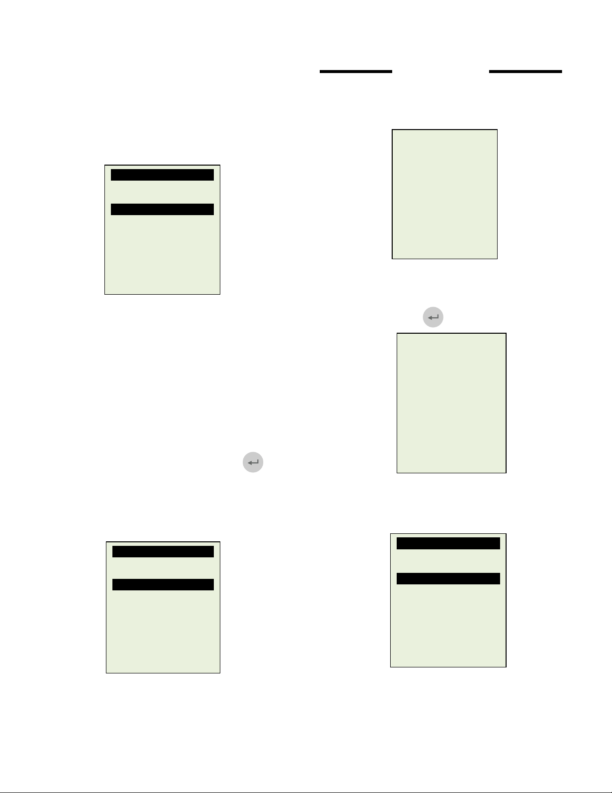
7. Pressing again will proceed to
Battery Test as shown below.
Select Rating
CCA
SAE
DIN
JIS
IEC
EN
CA
Unknown
8. Select the rating system: CCA, SAE, DIN,
JIS#, IEC, EN, CA; according to the battery
rating. If you cannot find its rating then select
Unknown.
9. If the battery is rated in JIS#, refer to the
conversion list provided to convert to CCA
rating before keying into the Analyser.
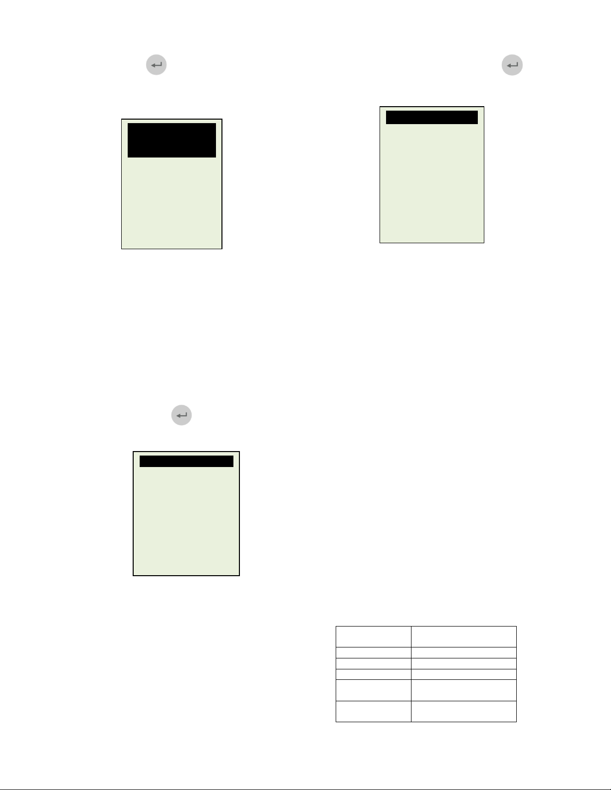
10. Once you had the system rating in mind,
select and press key and the display
will show:
Key in the battery rating values using the
or key for increase or decreases the
values by step of 100 units. For double digits
increase or decrease, use the or key by
step of 5 units each press.
Input Battery Rating
Increase/decrease:
Single digit
⊳ By hundredth
500 CCA
Press [Enter] to
proceed.
3
11. Once the rating is confirmed, press
key will start the testing process and will
display the result in less than 5 sec.
Battery: Good
Measured: 406 CCA
Rating: 630 CCA
Volts: 12.45 V
Int. R: 6.72 mOhm
Life: 76%
RESULTS: Good
‘Good’ indicates the battery in good
condition. ‘Replace’ indicates that the battery
needs to be replaced.
Voltage: 12.45V
This indicates the tested battery voltage
(12.45V). It depends on the stage of charge
on the battery:
CCA (Cold Cranking Amps): 406 CCA
CCA rating is being used here. If other rating
(SAE or DIN or JIS# or IEC or EN or CA)
then it will base on the selected respective
rating to calculate the results.
Int. R (Internal Resistance): 6.72mΩ
Internal resistance should fall between
2.0mΩ ~ 15.0mΩ for normal condition.
LIFE: 76%
Indicates the battery life expectancy in
percentage.
If the reading is greater than 45%,
RESULT will display Good. Anything less
than 45%, RESULT display Replace.
ROUGH CCA GUIDE
Given below is a rough CCA ratings guide for any
unknown battery model basing on the capacity of the
vehicle:
Capacity
1200 ~ 1600 cc 350 CCA
1600 ~ 2000 cc 500 CCA
2000 ~ 3000 cc 650 CCA
3000 cc and
above
M. Benz over
3000 cc
CCA Rating
750 CCA
760 A
Page 4

12. Press key will return to the Main Menu
as shown below:
13. Pressing key once will scroll down to the
“Grounding Test”
14. Press key will proceed to the display
as follows.
15. Now transfer the BLACK tester clip from the
battery [-] terminal to a suitable position on
the engine or chassis body leaving the RED
clip still attached to the battery [+] terminal.
Select Test
Battery Test
Grounding Test
Starter Test
Alternator Test
Then press [Enter].
Grounding Test
Select Test
Battery Test
Grounding Test
Starter Test
Alternator Test
Then press [Enter]
Grounding Test
Clip the Black clip to
engine body or the car
chassis and the Red
clip to the battery [+]
post.
16. Now press key again and it will starts
analysing.
Analysing ...
Please wait!
17. Once it has finished analysing, it will prompt
you with an instruction stating that you should
unclamp the Black tester clip from the engine
or chassis body and transfer to the battery
negative [-] terminal within 20 seconds time
limit if not the testing procedure has to be
repeated again as the gathered data will be
lost.
Grounding Test
Now transfer the Black
clip to the battery [-]
post.
The time limit given is
20 seconds before the
memory is lost.
NOTE: 20 seconds is given to establish the
contact to the battery [-] post failing which the
data obtained earlier will be lost. Then you
need to repeat the whole testing procedures
again.
18. Once the Black clip is clamped onto the
battery [-] terminal, the Analyser display will
light up as shown.
Grounding Test
Press [Enter] to
continue the test.
4
Page 5

19. Now you need to press key to proceed
and the display will show as follows
20. If the measured resistance reading is within
limits, then it will display as follows:
21. If the measured resistance reading has gone
beyond the limits, then it will display the
screen as follows:
Note:
The above indicates that the ground contact
from the engine body to the battery is bad.
Check for rusted or corroded point of contacts.
If found, dismantle it for cleaning or replace
before fixing back. Repeat the test again after
fixing.
Analysing ...
Please wait!
Results: OK
The grounding
resistance of the
engine or car chassis
is within limit.
Results: High Ohms
The grounding
resistance of the engine
or car chassis is high.
Clean the cable
contacts or replace
cable if necessary.
22. If you did not follow the right procedures
during the testing, it will display the results
as follows:
Results: Not detected
Wrong procedures.
Try again and follow
the step by step
instructions given.
23. To exit the program, pressing the key
at any moment will exit and return back to
main menu screen
Starter Test
Note: Before performing this test, make sure
that the battery is fully charged and in
good condition.
24. With engine OFF, place the vehicle
transmission in NEUTRAL for Manual and
PARK for Automatic then apply the parking
brake.
25. Pressing key once will scroll down to the
“Starter Test”
Select Test
Battery Test
Grounding Test
Starter Test
Alternator Test
Then press [Enter].
5
Page 6

26. Press key to continue and the display
will show as follows:
27. Switch the ignition key to ON and start
28. If the voltage drop is too great during the
Starter Test
Battery: 12.45V
Crank engine now
until it starts. Then
press [Enter].
cranking the engine until it starts. Immediately
after that press key and the results will
show as follows:
Result: OK
Min. Volts: 10.56V
Volt Drop: Normal
Press [Exit] to main
menu.
cranking, the tested results will display as
follows and will prompt you to check the
starter system.
Result: High Drop
Min. Volts: 8.56V
Volt Drop: High
Check starter relay,
battery terminals or
battery has aged.
Press [Exit] to main
menu.
29. During cranking when it detects that there is
no drop in voltage, it will display the following
screen:
Result: Not detected
No change in volt drop.
Check clamping at
battery side and test
again.
Press [Exit] to main
menu.
30. To exit the program, pressing the
key at any moment will exit and return back
to the main menu screen.
No load testing at 3000 RPM:
31. With engine OFF, place the vehicle
transmission in NEUTRAL for Manual and
PARK for Automatic and apply the parking
brake.
32. Pressing key once will scroll down to the
“Alternator Test”
Alternator Test
Select Test
Battery Test
Grounding Test
Starter Test
Alternator Test
Then press [Enter]
6
Page 7

33. Press key to continue and the display
will show:
34. Starts the engine then press key again
and the screen will prompt you as shown
below:
35.
After that press key again and it
show as below:
36. Press key will show the results of the
test:
No Load Test
Start the car engine and
keep it running.
Then press [Enter] to
begin.
No Load Test
Make sure all electrical
loads are turn OFF. Rev
the engine to 3,000 rpm.
Press [Enter].Hold on to
this 3,000 rpm for 10
seconds and release the
pedal.
No Load Test
At 3,000 rpm:
Av Volts: 14.2V
<15.0V: Max. 14.6V
>13.3V: Min. 13.8V
Press [Enter] for results.
Results: Good
At 3,000 rpm,
No load Test:
Average Charging
Volts: 14.2V
Press [Enter] to
continue to Loading
Test.
37. If either minimum or maximum charging volts
are not within the voltage range limits then it
will display one of the screen as below (Fig. 1
& Fig. 2) and it will prompt you to check the
alternator system for the fault.
Results: Low charge
At 3,000 rpm,
No load Test:
>13.3V: Min 13.2V
Check for loose belt
and the alternator.
Fig.1
Results: High charge
At 3,000 rpm,
No load Test:
<15.0V: Max. 15.6V
Check alternator and the
regulator.
Fig.2
7
Page 8

Testing with load at 2,000 RPM:
This test is to check the alternator’s
behavior during loading.
38. Continue from the previous test, proceed to
the next step by pressing key will enter
to the display as follows.
Loading Test
Switch ON all electrical
loads. Rev engine up to
2,000 rpm. Press
[Enter].Hold on to this
2,000 rpm for 10
seconds and release the
pedal.
39. You need to switch ON all loads (Head
Lights, Radio, Air-condition, Heater, etc) and
press key and it show as below:
40. Press key again and the result will be
Loading Test
At 2,000 rpm:
Av.Volts: 13.3V
>13.5V: Max. 13.8V
>12.5V: Min. 12.8V
Press [Enter] for
results.
shown as below:
Results: Good
At 2,000 rpm,
Loading Test:
Average Charging
Volts: 13.3V
41. If either minimum or maximum charging volts
are not within the voltage range limits then it
will display one of the screen as below (Fig. 3
& Fig. 4) and it will prompt you to check the
alternator system for the fault.
Fig.3
Fig.4
42. To exit the program, pressing the key
at any moment will exit and return back to the
main menu screen.
Results: Low charge
At 2,000 rpm,
Loading Test:
>13.5V: Max. 13.3V
Check for loose belt
and the alternator.
Results: Low charge
At 2,000 rpm,
Loading Test:
>12.5V: Min. 12.4V
Check for loose belt
and the alternator.
8
Page 9

HELP KEY
43. Selecting this key will help you familiarize with
the analyser by explaining the various
functions and the results.
To access to this function, just press the
key during the wakeup and the display:
44. Use the or key to scroll to the item you
45. Press key to scroll to next page.
46. To exit this function, just press the key
will return back to the main menu display.
Battery Test
How to operate
Voltage
Battery ratings
Internal R.
LIFE
Press [Help] to read
[Exit] to menu.
need and then press
How to operate
Operation:
Engine must be OFF.
Locate the battery.
Clamp Tester to Battery
[+] and [-] posts. Check
battery rating [CCA,
SAE, JIS, DIN, IEC, EN,
CA].Key the rating
values. The Tester will
lead you through the
whole testing process.
posts. Check battery
rating [CCA, SAE, JIS,
DIN, IEC, EN, CA].Key
the rating values. The
Tester will lead you
through the whole
testing process.
[Exit] to menu.
PRINTING THE LAST TEST RESULTS
Printing all the Last Test Results can only be done
while in this View Last Test mode. This is to ensure
that the results printed will be the final ones as every
test redone will be updated in its memory.
Select Menu
New: Clear Memory
Continue Testing
View last Test
Setup Menu
Press key will proceed to display the last test
results depends on the type of test you had performed
earlier.
Then press [Enter].
Battery: Good
Measured: 406 CCA
Rating: 630 CCA
Volts: 12.45 V
Int. R: 6.72 mOhm
Life: 76%
Important:
The tester has to be connected to a 12V battery
in order to work with the mobile printer. This is
because it needs higher Amps to operate which
the PC USB output is unable to provide.
To print 1 test at a time, just press key on,
while the test results are still on the screen. The
mobile printer will start printing.
Battery: Good
Measured: 406 CCA
Rating: 630 CCA
Volts: 12.45 V
Int. R: 6.72 mOhm
Life: 76%
9
Page 10

10
Figure
5
a
Figure
5
b
Figure
5
c
PRINTER SETUP
SELECT DISPLAY LANGUAGE
1. The printer will only work when connected
directly to a 12Volt car battery because it
needs higher amps than an USB port from
the PC can provide. The red LED indicates
the printer is ON and the green LED will blink
when the printer has run out of paper. If
there is paper present and it still blinks then
the printer has overheating problem. The
green LED will also stay lighted up when
there is no paper if BST 12 is connected to
the PC through the USB port.
2. Open the printer cover (Fig. 5a). Place the
thermo paper roll into the slot with the paper
edge facing up (Fig. 5b). Make sure the
paper is about ¾ in out when the printer
cover is closed (Figure 5c).
1. To change the display language of the
Analyser, first go to Setup Menu by pressing
key until it has been highlighted and then
press key to enter.
Inside the Setup Menu press to gain access to the
Language Menu
Select the preferred language by pressing key to
scroll to the item.
Select Menu
New: Clear Memory
Continue Testing
View last Test
Setup Menu
Then press [Enter].
Setup Menu
Language
LCD Brightness
Printer
PC Link
[Enter] to proceed.
[Exit] to quit.
Select Language
English
Deutsch
Español
Italiano
[Enter] to save.
Page 11

Then confirm it by pressing save. Once it had
been saved, the display will change to the language
selected. Press key to exit and get back to
the Main menu screen to continue your test.
PC LINK
2. This analyser is also designed to link with PC
for data storage and printout through normal
printer. To do so, the PC has to install the
driver and the software provided in order to
operate.
3. Select the correct driver for your computer
operating system and double click on the icon
followed by the PC set-up.
11
4. Now link up BESA with PC. In the Setup
Menu display press key to highlight
“PC Link” and then press key to
activate.
5. To confirm the whether there is
communication; click on [Get Data From] tab
and the Last Test Result will appear. See
example below.
 Loading...