

Asset ATLANTIS 60, ATLANTIS 180 Touch TT, ATLANTIS 120, ATLANTIS 180 US Installation, User And Maintenance Manual
Page 1
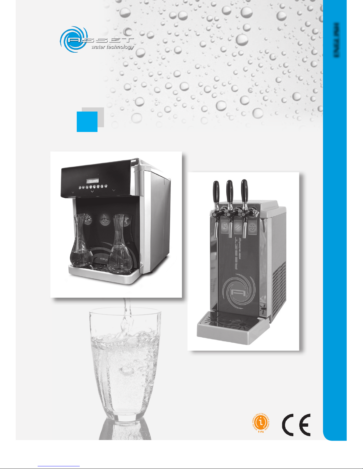
Rev. February 2011 - Code Man-02-ENG
ASSET S.r.l. Loc. Isola del Pero, 16 - 17041 - ALTARE (SV) - ITALY
Tel: +39 019 58 48 30 Fax: +39 019 51 42 186 - e-mail: [email protected] - www.assetitalia.it
ENGLISH
Installation, User and
Maintenance Manual
prodotto conforme
D.M.174/2004
ATLANTIS
Page 2
ABSENCE
ME TAL
HEAVY
94/6 2/CE
prodotto conforme
D.M.174/2004
Certificate Number TIFQ-1206TA03F3P7
Page 3

I-1
ATLANTIS - Installation, Use and Maintenance - Man cod.-02 - Rev. 02/2011
Table of Contents
CHAPTER 1
INTRODUCTION .................................... 1-3
1.1 General information .................................... 1-3
1.2 Aim ofo the manual .................................... 1-4
1.3 Where and how to keep the manual ................... 1-4
1-4 Manual updating .................................... 1-5
1.5 Cooperation with the user ................................ 1-5
1.6 Manufacturer .................................... 1-6
1.7 Manufacturer’s responsibility and warranty ........ 1-7
1.7.1 warranty terms .....................................1-7
1.8 Thecnical assistance service .............................. 1-8
1.9 Copyright .................................... 1-8
CHAPTER 2
TECHNOLOGICAL DESCRIPTION .................................... 2-1
2.1 Available models .................................... 2-1
2.1.1 atlantis 60/120 .....................................2-1
2.2 Technical data .................................... 2-2
2.3 Emission of machine noise ............................... 2-5
CHAPTER 3
SAFETY REQUIREMENTS .................................... 3-1
3.1 General notes .................................... 3-1
3.2 Symbols .................................... 3-1
3.3 Safety warnings .................................... 3-2
3.3.1 operator’s qualification .....................................3-3
CHAPTER 4
UNPACKING .................................... 4-1
4.1 Visial check .................................... 4-1
4.1.1 check of machine and equipment supplied ..............4-1
4.2 Unpacking .................................... 4-2
4.3 Packing list .................................... 4-2
CHAPTER 5
INSTALLATION .................................... 5-1
5.1 Environmental characteristics ........................... 5-1
5.2 Cleaning .................................... 5-1
5.3 Positioning .................................... 5-1
5.4 Connections .................................... 5-2
5.4.1 outer accessories .....................................5-2
5.4.2 taps assembly .....................................5-3
5.4.3 water filter insertion (optional) ...........................5-4
5.4.4 insertion of the litrecounter (optional) .................5-4
5.4.5 connection to the water mains ............................5-5
5.4.6 power supply connection .................................... 5-6
5.4.7 connection of the Co2 ..................................... 5-7
Page 4

I-2
ATLANTIS - Installation, Use and Maintenance - Man cod.-02 - Rev. 02/2011
CHAPTER 6
DISPENSER USE ....................................6-1
6.1 Control panel ....................................6-1
6.2 First start up ....................................6-2
6.3 Temperature setting ....................................6-4
6.4 Ice bank defrosting ....................................6-4
6.5 Ice bank emptying and ice bank water
replacement .................................... 6-5
6.6 Touch screen user interface .............................. 6-6
6.7 Anomalies signalling leds ................................ 6-7
6.8 Touch Models Dispay .................................... 6-7
6.9 Water Temperature Adjustment ........................6-8
6.10 Energy Saving Function .................................... 6-8
6.11 Automatic Water Dispesing Dosage ................... 6-9
6.12 Enable Tone .................................. 6-10
6.13 Keyboard Lock .................................. 6-11
6.18 Dedicated Litre Counter .................................. 6-12
6.19 Firmware Version .................................. 6-12
CHAPTER 7
TROUBLE SHOOTING .................................... 7-1
7.1 Solutions to problems .................................... 7-1
CHAPTER 8
MAINTENANCE .................................... 8-1
8.1 Ordinary scheduled maintenance cycles
(HACCP) .................................... 8-1
8.2 Replacement of the monouse or rechargeable
CO2 bottle .................................... 8-2
8.2.1 replacement of the monouse bottle ...................... 8-2
8.2.2 replacement of the rechargeable bottle .................. 8-2
8.3 Filter replacement .................................... 8-3
8.4 Replacement of the UV lamp (outer accessory) .. 8-5
8.5 Cleaning .................................... 8-5
8.6 Water dispenser sanitization ............................. 8-6
8.6.1 dispenser sanitization procedure
(with Everpure filter) ..................................... 8-6
8.6.2 Tap sanitization .....................................8-7
8.7 Technical assistance .................................... 8-8
CHAPTER 9
DISMANTLING .................................... 9-1
9.1 Dispenser dismantling .................................... 9-1
9.2 Electronic components disposal ........................ 9-1
CHAPTER 10
SPARE PARTS ..................................... 10-1
10.1 Identification and ordering modes .....................10-1
Page 5

I-3
ATLANTIS - Installation, Use and Maintenance - Man cod.-02 - Rev. 02/2011
Page 6

I-4
ATLANTIS - Installation, Use and Maintenance - Man cod.-02 - Rev. 02/2011
Page 7

I-5
ATLANTIS - Installation, Use and Maintenance - Man cod.-02 - Rev. 02/2011
Pictures summary
CHAPTER 1
INTRODUCTION .................................... 1-3
Fig
1.1 Atlantis ..................................... 1-3
1.2 Atlantis 180 Touch .....................................1-3
1.3 Atlantis 180 US ..................................... 1-3
1.4 Identification label on the dispenser back side .......1-6
CHAPTER 2
TECHNOLOGICAL DESCRIPTION .................................... 2-1
Fig
2.1 Atlantis ..................................... 2-1
2.2 Atlantis parts description ....................................2-2
CHAPTER 4
UNPACKING .................................... 4-1
Fig
4.1 Packaging ..................................... 4-1
CHAPTER 5
INSTALLATION .................................... 5-1
Fig
5.1a Outer connections on upper part of Atlantis 120 .....5-2
5.1b Outer connections on back side of Atlantis 120 ....... 5-2
5.2 Outer connections on back side of Atlantis 60 .........5-2
5.3 Taps assembly ..................................... 5-3
5.4 Taps tightening ..................................... 5-3
5.5 Stainless steel tap for sparkling water ...................5-3
5.6 Spanner for taps tightening .................................5-3
5.7 Litrecounter .....................................5-4
5.8 Drinking water pipe connection to mains ...............5-5
5.9 Power supply cable connection ............................. 5-6
5.10 CO2 gas pipe connection ..................................... 5-7
5.11 Rechargeable bottle .....................................5-7
5.12 Rechargeable bottle pressure reducer ..................... 5-7
5.13 Monouse bottle .....................................5-7
5.14 Rechargeable bottle opening ................................ 5-8
5.15 Pressure reducer opening ..................................... 5-8
CHAPTER 6
START UP AND OPERATION .................................... 6-1
Fig
6.1 Atlantis ..................................... 6-1
6.2 Control panel ..................................... 6-1
6.3 Dispenser upper cover opening ............................. 6-2
6.4 Dispenser upper part ..................................... 6-2
6.5 Rechargeable bottle opening ................................ 6-2
6.6 Pressure reducer adjustment ................................. 6-2
Page 8

I-6
ATLANTIS - Installation, Use and Maintenance - Man cod.-02 - Rev. 02/2011
6.7 Dispenser upper part ..................................... 6-3
6.8 Safety valve ring ..................................... 6-3
6.9 Cold water dispensing tap .................................... 6-4
6.10 Thermostat for water temperature adjustment ......... 6-4
6.11 Control Panel (Touch Models) ...............................6-7
CHAPTER 8
MAINTENANCE .................................... 8-1
Fig
8.1 Monouse bottle replacement ...............................8-2
8.2 Rechargeable bottle replacement .........................8-2
8.3 Chip card slot (Touch Model only) ........................8-4
Page 9

1-1
ATLANTIS - Installation, Use and Maintenance - Man cod.-02 - Rev. 02/2011
Dear Customer,
Asset Srl would like to thank you and congratulate for your
choice.
Water is a vital and essential element. Water represents 70%
of the human body and, every day, we ought to drink at least
2 litres of it to be in health and to refresh ourselves.
For this reason, the most important thing to do is to be sure of
the goodness and quality of the water we daily drink.
This useful and functional dispenser with MICROFILTRATION
system is manufactured with the most modern and innovative
technologies. Its quality materials are subjected to a rigorous
control according to our company standard. All the materials
and components are tested during the entire production process to satisfy your expectations.
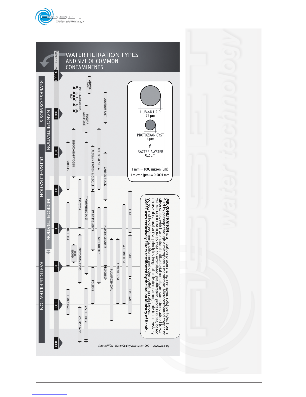
MICROFILTRATION is a filtration process which removes solid particles from a fluid by passage through a microporous
membrane. Microperforated copper or silver scales, which are
natural antibacterial metals, are sometimes added to water
MICROFILTRATION so that an articulated pre-filtration process
is set, based on use of natural active principles (vegetal activated carbon) able to extensively collect and hold sediments,
chlorine and other polluting substances.
ASSET uses exclusively Filters certificated by the Italian Ministry of Heath.
ATTENTION: On the table shown on the next page it is possible
to check which elements are filtered by the dispenser through
MICROFILTRATION.
We ask you to read and respect these simple instructions to
guarantee the best results, since at the first use of the dispenser.
This manual includes important information, not only for the
use but, also, for your safety and for maintenance; it is part
of the machine.
ATTENTION: It is necessary to carry out periodical maintenance on this device in order to preserve
the drinkable characteristics of dispensed water.
Page 10
1-2
ATLANTIS - Installation, Use and Maintenance - Man cod.-02 - Rev. 02/2011
Page 11
1-3
ATLANTIS - Installation, Use and Maintenance - Man cod.-02 - Rev. 02/2011
1.1 General information
The machine is realized in compliance with the directives
in force in the European Community and with the required
technical rules, as certified by the Declaration of Conformity
issued by the Manufacturer and enclosed to the manual.
This publication, hereinafter simply called the ”manual”,
includes all the information for use and for a safe maintenance of the device mentioned in the Declaration of
Conformity.
This device, that in the course of the manual will be generically called “machine” or “dispenser”, is manufactured
by the company ASSET srl, whose details are indicated
hereinafter in this publication.
This publication is intended for subjects, generically
defined as ‘users’, who are intended to use the machine.
In particular, they can be identified as follows:
- operators directly involved in transport, storage, in-
stallation, use and ordinary/extraordinary maintenance
of the machine, from its launch onto the market up to
the day of disposal;
- direct users.
The original text of this publication, drawn up in Italian
language, represents the only reference for the settlement
of possible disputes related to the interpretation of the
translation in the community languages.
This publication must be considered as an integral part
of the machine, and therefore it must be preserved for
future reference up to the final disposal and scrapping
of the machine.
1. Introduction
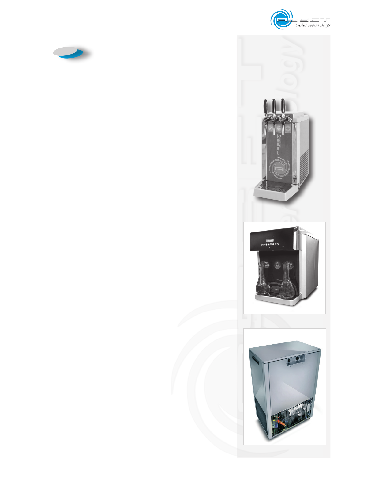
fig.1.1 ATLANTIS 60/120
fig.1.2 ATLANTIS 180 Touch TT
fig.1.3 ATLANTIS 180 US
Page 12

1-4
ATLANTIS - Installation, Use and Maintenance - Man cod.-02 - Rev. 02/2011
1.2 Aim of the manual
The aim of this manual is to give the indications to use
the machine safely and to carry out the ordinary maintenance procedures.
Any calibrations, adjustments and extraordinary maintenance operations are not included in this booklet, since
they are carried out exclusively by the service technician, that must operate on the machine in respect of
the technical and project characteristics for which is
was manufactured.
The machine intended use and configuration are the only
ones admitted by the Manufacturer; do not try to use
the machine disagreeing with the indications supplied.
Any other use or configuration must be previously agreed
upon with the Manufacturer in writing, and be enclosed
to this manual.
Concerning installation and use, the user must follow the
specific laws in force in the Nation where the machine
is installed.
The user is expected to know and consult the laws,
directives, etc. recalled in the text in order to achieve
the aims that the manual sets.
1.3 Where and how to keep the
manual
This manual (and any possible enclosures related to it)
must be kept in a protected and dry place, and always
be available for reference.
It is recommended to make a copy of the manual and
keep it in the archive.
Refer to the data of the machine identification label
when exchanging information with the Manufacturer or
with authorized assistance staff.
This manual must be kept for the whole life of the machine,
and in case of need (for ex. damage that compromises
consulting it also partially) the user must obtain a new
copy by requesting it exclusively to the Manufacturer,
indicating the publication code positioned on the cover.
Page 13

1-5
ATLANTIS - Installation, Use and Maintenance - Man cod.-02 - Rev. 02/2011
1.4 Manual updating
The Manual reflects the machine state of art at the time
of its launch onto the market, being an integral part of it.
The publication is compliant with the directives in force
at that time; the Manual cannot be considered unsuitable
further to possible updates of standards or modifications
on the machine.
Any supplements of the Manual that the Manufacturer
considers suitable to send to the users, must be kept with
the Manual and become an integral part of it. To check if
this Manual version is the last one available, please visit
the Manufacturer website at www.assetitalia.it , where –
on every single product page - it is possible to download
the electronic version (as a pdf file) of the last updated
Manual release.
1.5 Cooperation with the user
The Manufacturer is available to supply additional information to customers and to consider any suggestions for
improvement in order to bring this manual more into line
with the requirements for which it was published.
If the machine is sold, the original user must give this
manual to the new user and communicate the address
of the new owner to the manufacturer so that it may be
provided with any essential information or updates.
All property rights of the contents included in this publication are reserved to Asset s.r.l., therefore it cannot be
reproduced totally or partly unless written authorization
by the manufacturer.
Page 14
1-6
ATLANTIS - Installation, Use and Maintenance - Man cod.-02 - Rev. 02/2011
1.6 Manufacturer
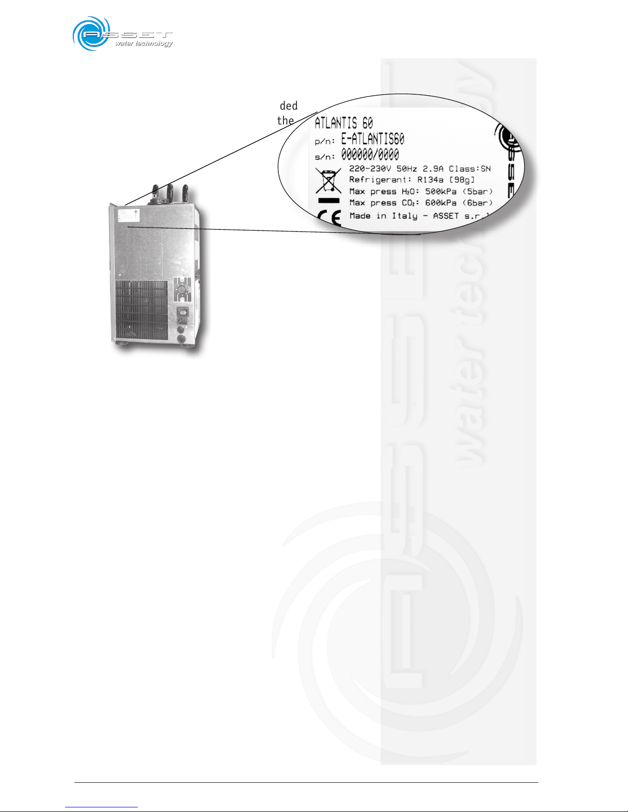
The machine identification data are included
in the label positioned on the rear of the
machine.
The label includes the following data in this order:
- model;
- serial number;
- power supply voltage (V), frequency (Hz), absorbency
only of the refrigerant part (A) and the pertaining
Climatic Class;
- type of refrigerant and quantity in grams;
- maximum pressure of the water supply to which the
dispenser can be connected (kPa);
- maximum pressure of the CO2 supply to which the
dispenser can be connected (kPa);
- country of manufacture;
- European CE conformity marking
ATTENTION: The removal or, however, every type of
tampering of the identification label, makes the
warranty expire.
fig.1.3
Page 15

1-7
ATLANTIS - Installation, Use and Maintenance - Man cod.-02 - Rev. 02/2011
1.7 Manufacturer’s responsibility
and warranty
In order to take advantage of the warranty supplied by the
Manufacturer, the user must carefully follow the measures
indicated in the manual, and in particular:
- always operate within the machine limit of use;
- always carry out constant and accurate cleaning and
maintenance operations;
The manufacturer declines any responsibility, direct and
indirect, caused by:
- machine use different than what indicated in this
manual;
- use by staff who did not read and fully understand the
contents of this manual;
- use not in conformity with specific standards in force
in the Country of installation;
- modifications carried out on the machine, on the
software, on the operation logic, if not authorized in
writing by the Manufacturer;
- unauthorized repairs;
- exceptional events.
If the machine is sold to third parties also this manual
must be delivered to the new owner; any right of the Purchaser will be automatically invalided if the manual is not
delivered, including the warranty terms where applicable.
If the machine is sold to third parties, in a Country where
is spoken a different language than the language indicated
in this manual, the old user is responsible to supply a
faithful translation of this manual in the language of the
Country where the machine will operate.
1.7.1 Warranty terms
The machine is guaranteed by ASSET srl for a 24 (twenty
four) month period from the invoice date.
This guarantee covers manufacturing and assembling defects.
ASSET srl undertakes to replace or repair at is own charge
at its factory, carriage free, any part that the manufacturer
considers defective.
If service by a repair technician of the Manufacturer (or
by a authorized technician) is required at the user’s site,
Page 16

1-8
ATLANTIS - Installation, Use and Maintenance - Man cod.-02 - Rev. 02/2011
it is understood that the travel, board and lodgings costs
are at user’s charge.
The acknowledgment of a free supply of the parts under
warrantee is always subject to inspection by the Manufacturer (or authorized person).
The extension of guarantee following a technical intervention or repair of the machine is excluded;
Damages to the machine are not included in the warrantee if caused by:
- transport;
- negligence;
- improper use and/or not in conformity with the
instructions given in the use manual;
- wrong electrical connection.
The warranty becomes null and void in case of:
- repairs carried out by staff not authorised of the
Manufacturer;
- modifications not authorized by the Manufacturer;
- use of parts and/or equipment not supplied or approved by the Manufacturer;
- identification label removal or tampering.
1.8 Technical assistance service
For any intervention of technical service directly contract
the Manufacturer or the authorised Dealer, and always
indicate the model and the serial number, imprinted on
the identification label.
1.9 Copyright
The information contained in this manual must not be
disclosed to third parties. Any reproduction, partial or
total, not authorized in writing by the Manufacturer,
obtained by photocopying, reproduction or with other
systems, also electronic acquisition, infringes the copyright
conditions and will be prosecuted according to the law.
Page 17
1-9
ATLANTIS - Installation, Use and Maintenance - Man cod.-02 - Rev. 02/2011
DICHIARAZIONE DI CONFORMITA’ CE
2004/118/EC, EC 2006/95/EC.
ASSET S.r.l.
Loc. Isola del Pero, 16 - 17041 Altare (SV) - Italy
dichiariamo sotto la nostra responsabilità che il
prodotto
EROGATORE D'ACQUA Modello
ATLANTIS
al quale si riferisce questa dichiarazione è conforme
alle seguenti norme:
• Sicurezza di elettrodomestici e apparecchi elettri-
ci - Parte 1 - Requisiti generali - EN 60335-1 (2002)
+ A1(2004) + A2(2006) + A11(2004) + A12 (2006) +
A13(2008).
• Sicurezza di elettrodomestici e apparecchi elettrici -
Parte 2-24 - Requisiti specici per apparecchiature refrigeranti, gelatiere e produttori di ghiaccio - EN 603352-24:2003 + A11:2004 + A1:2005 + A2:2007.
• Metodi di misurazione per campi elettromagnetici in
apparecchi elettrici di uso domestico e similari con riferimento all’esposizione umana - EN 62233:2008.
• Sicurezza di elettrodomestici e apparecchi elettrici
- Parte 2-15 - Requisiti specici per apparecchi per
riscaldare liquidi - EN 60335-2-15:2002 + A1:2005 +
A2:2008.
• Compatibilità elettromagnetica (EMC) - Requisiti di
emisissioni per apparecchi elettrici di uso domestico e
similari - Parte 1 - Emissioni - EN 55014-1:2006.
• Compatibilità elettromagnetica (EMC) - Requisiti di
immunità per apparecchi elettrici di uso domestico e
similari - Parte 2 - Immunità - Norma per famiglia di
prodotti - EN 55014-2:1997 + A1:2001.
• Compatibilità elettromagnetica (EMC) - Parte 3-2 - Li-
miti - Limiti per le emissioni di corrente armonica (corrente in ingresso dell’apparecchiatura ≤ 16A per fase)
- EN 61000-3-2:2006.
• Compatibilità elettromagnetica (EMC) - Parte 3-3 - Li-
miti - Limitazione delle uttuazioni del voltaggio e dei
picchi di tensione nei sistemi di alimentazione a bassa
tensione per apparecchiature con corrente nominale ≤
16A. - EN 61000-3-3:1995 + A1:2001 + A2:2005.
Secondo le disposizioni delle direttive:
2004/108/EEC, 2006/95/EC.
Altare (SV), lì 15/01/2011
Project Manager
Paolo Tesi
EC DECLARATION OF CONFORMITY
2004/118/EC, 2006/95/EC.
ASSET S.r.l.
Loc. Isola del Pero, 16 - 17041 Altare (SV) - Italy
declare under our responsability that the
product
WATER DISPENSER Model
ATLANTIS
to which this declaration relates is in conformity with the
following standards or other normative documents:
• Household and similar electrical appliances - Safety
- Part 1: General requirements - EN 60335-1:2002
+ A1:2004 + A2:2006 + A11:2004 + A12:2006 +
A13:2008.
• Safety of household and electrical appliances - Part
2-24 : Particular requirements for refrigerating appliances, ice-cream appliances and ice-makers - EN
60335-2-24:2003 + A11:2004 + A1:2005 + A2:2007.
• Measurement methods for electromagnetic elds of
household appliances and similar apparatus with regard to human exposure - EN 62233:2008.
• Household and similar electrical appliances - Safety
- Part 2-15: Particular requirements for appliances for
heating liquids - EN 60335-2-15:2002 + A1:2005 +
A2:2008.
• Electromagnetic compatibility (EMC) - Requirements
for household appliances, electric tools and similar apparatus - Part 1: Emission - EN 55014-1:2006.
• Electromagnetic compatibility (EMC) - Requirements
for household appliances, electric tools and similar apparatus - Part 2: Immunity - Product family standard
- EN 55014-2:1997 + A1:2001.
• Electromagnetic compatibility (EMC) - Part 3-2: Limits
- Limits for harmonic current emissions (equipment input current ≤ 16 A per phase) - EN 61000-3-2:2006.
• Electromagnetic compatibility (EMC) - Part 3-3: Limits
- Limitation of voltage changes, voltage uctuations
and icker in public low-voltage supply systems, for
equipment with rated current ≤ 16 A per phase and not
subject to conditional connection - EN 61000-3-3:1995
+ A1:2001 + A2:2005.
Following the provision of the directives:
2004/108/EEC, 2006/95/EC.
Altare (SV) - February 15
th
, 2011
Project Manager
Paolo Tesi
Page 18

1-10
ATLANTIS - Installation, Use and Maintenance - Man cod.-02 - Rev. 02/2011
Intentionally blank page
Page 19
2-1
ATLANTIS - Installation, Use and Maintenance - Man cod.-02 - Rev. 02/2011
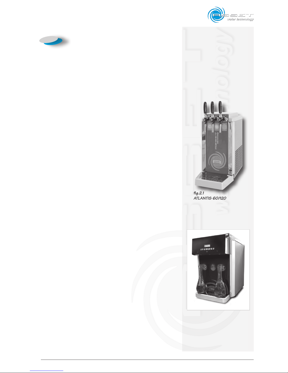
2.1 Available models
1 ATLANTIS 60
2 ATLANTIS 120
3 ATLANTIS 180 Touch TT
ATLANTIS 60 and ATLANTIS 120 featured by three lever
dispensing taps.
ATLANTIS 180 Touch featured by a front Touch panel with
a multi-function display.
2.1.1 ATLANTIS 60/120/180
Stainless steel and first quality Italian components ensure
reliability and strength to this Made in Italy gem.
ATLANTIS is the new range of water dispensers, table
top and under counter, that Asset has conceived for the
HoReCa (Hotel, Restaurant, Cafè) sector.
Asset is present where best performance and immediate
support is required, making available to the Customer a
direct pre-sale consulting line and an after-sales support,
very important values in this professional segment.
By using the “Ice Bank” technology, the ATLANTIS range
dispenses 60, 120 or 180 litres per hour, completely satisfying the demand of small, medium and big restaurants
with high performances and compact dimensions.
The ATLANTIS 60/120/180 range is a quiet, easy to install
and use dispenser with low power consumption that stands
out for its stylish line and compactness.
2. Technological description
fig.2.1
ATLANTIS 60/120
ATLANTIS 180 Touch TT
Page 20
2-2
ATLANTIS - Installation, Use and Maintenance - Man cod.-02 - Rev. 02/2011
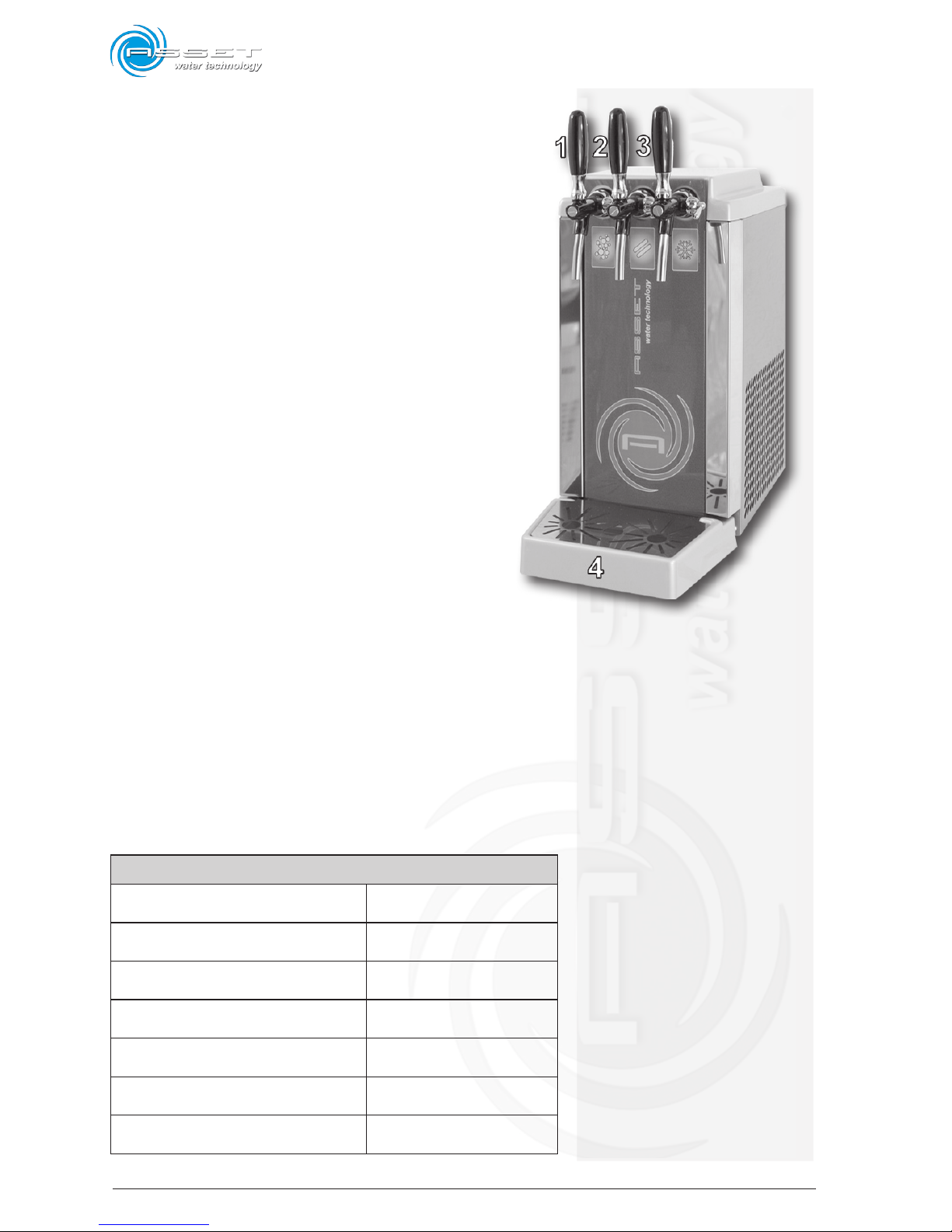
1 cold sparkling water dispensing tap;
2 room temperature water dispensing tap;
3 cold water dispensing tap;
4 drip tray equipped with supporting grid.
2.2 Technical data
The following data are related to the dispenser with
serial configuration.
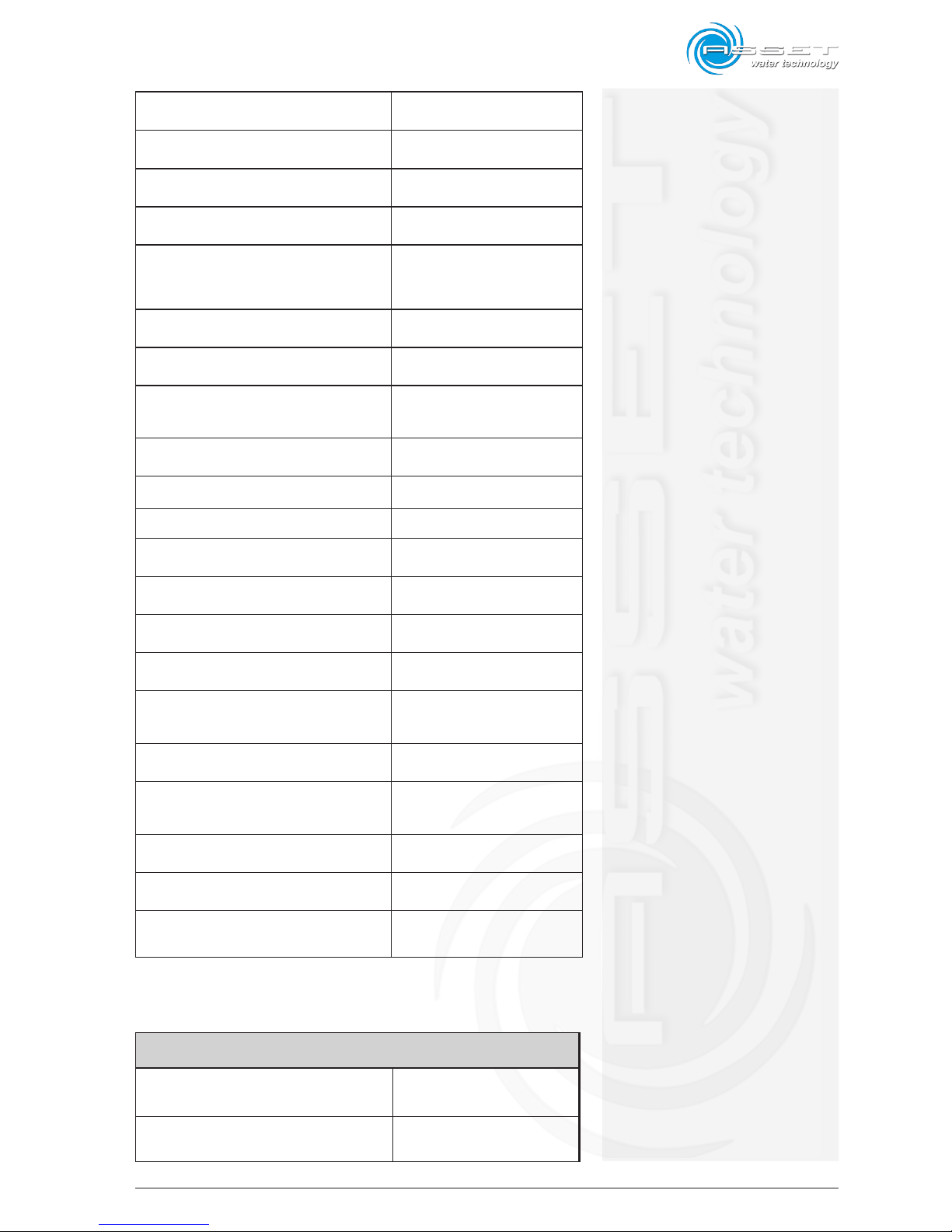
ATLANTIS 60
TABLE TOP
POWER SUPPLY VOLTAGE
220/230V 50/60Hz
monophase
MAX POWER CONSUMPTION
670W - 2,9A
Climatic Class SN
ROOM WORK TEMPERATURE 10-32 °C / 50-89,6°F
COMPRESSOR POWER Hermetic 65W
QUANTITY OF REFRIGERANT GAS R134a 98g
CONDENSATION OF VENTILATED AIR YES
WATER PUMP TYPE Rotary
fig.2.2
Page 21
2-3
ATLANTIS - Installation, Use and Maintenance - Man cod.-02 - Rev. 02/2011
CARBONATION SYSTEM Saturator
MINIMUM INLET WATER TEMPERATURE 5 °C / 41°F
MAXIMUM INLET WATER TEMPERATURE 25 °C / 77°F
DISPENSED WATER TEMPERATURE Adjustable 2÷8 °C
COLD AND SPARKLING WATER OUTPUT
16l/h ∆t = 10 °C / 50 °F
(Room Temperature 25°C /
77°F - Humidity 75%)
WATER INLET FITTING
Quick Fitting - Ø 8mm
CO2 INLET FITTING
Quick Fitting - Ø 8mm
WATER SYSTEM WORKING PRESSURE
MIN-MAX
1.5 – 5 bar
CARBONATOR CAPACITY 2 l
ICE BANK TANK CAPACITY 16 l
ICE BANK 8 Kg
CO2 WORKING PRESSURE MIN-MAX 3.5 – 6 bar
NET WEIGHT (ACCESSORIES EXCLUDED) 25 kg
GROSS WEIGHT (ACCESSORIES EXCLUDED)
29 kg
WEIGHT WITH PACKAGE 33 kg
DISPENSER DIMENSIONS LxWxH
INCLUDING DRIP TRAY
260X450X485mm
PACKAGE DIMENSIONS LxWxH 310X380X540mm
HAND DISPENSING TAP WITH FLOW
REGULATION
1 for each type of water
dispensed
SOUND PRESSURE LEVEL 50 dB(A)
SOUND POWER LEVEL 62 dB(A)
STORAGE TEMPERATURE min/max
Min 2°C/35,6 °F - Max 40
°C/104 °F
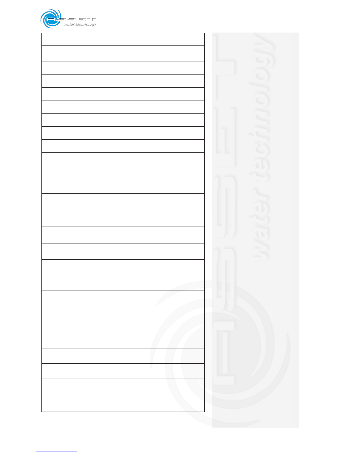
ATLANTIS 120
TABLE TOP
POWER SUPPLY VOLTAGE
220/230V 50/60Hz
monophase
MAX POWER CONSUMPTION
830W - 3,6A
Climatic Class SN
Page 22
2-4
ATLANTIS - Installation, Use and Maintenance - Man cod.-02 - Rev. 02/2011
ROOM WORK TEMPERATURE 10-32 °C / 50-89,6°F
COMPRESSOR POWER 350W
QUANTITY OF REFRIGERANT GAS R134a 125g
CONDENSATION OF VENTILATED AIR YES
WATER PUMP TYPE Rotary
CARBONATION SYSTEM Saturator
MINIMUM INLET WATER TEMPERATURE 5 °C / 41°F
MAXIMUM INLET WATER TEMPERATURE 25 °C / 77 °F
DISPENSED WATER TEMPERATURE Adjustable 2÷8 °C
COLD AND SPARKLING WATER OUTPUT
120l/h ∆t = 10 °C / 50 °F
(Room Temperature 25°C /
77°F - Humidity 75%)
WATER SYSTEM WORKING PRESSUR
MIN-MAX
1.5 - 5 bar
CARBONATOR CAPACITY 2.5 l
ICE BANK TANK CAPACITY 16 l
ICE BANK 8 Kg
MIN - MAX CO2 WORKING PRESSURE 3.5 - 6 bar
NET WEIGHT (ACCESSORIES EXCLUDED) 27 kg
GROSS WEIGHT (ACCESSORIES EXCLUDED)
35 Kg
WEIGHT WITH PACKAGE 30 kg
DISPENSER DIMENSIONS LxWxH
INCLUDING DRIP TRAY
260X597X485mm.
PACKAGE DIMENSIONS LxWxH 310X520X540mm
HAND DISPENSING TAP WITH FLOW
REGULATION
1 for each type of water
dispensed
SOUND PRESSURE LEVEL 50 dB(A)
SOUND POWER LEVEL 62 dB(A)
STORAGE TEMPERATURE min/max
Min 2°C/35,6 °F - Max 40
°C/104 °F
DRAIN PIPE FOR TANK TOO FULL Directly in the drip tray
Page 23
2-5
ATLANTIS - Installation, Use and Maintenance - Man cod.-02 - Rev. 02/2011
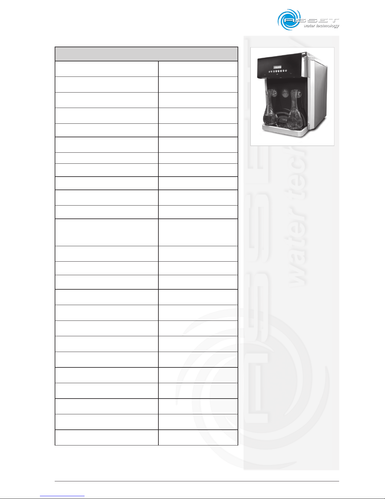
ATLANTIS 180 Touch TT
TABLE TOP
POWER SUPPLY VOLTAGE
220/230V 50/60Hz
monophase
MAX POWER CONSUMPTION
680W - 3,1A
Climatic Class SN
ROOM WORK TEMPERATURE 10-32 °C / 50-89,6°F
COMPRESSOR POWER 520W - 1/3 Hp
QUANTITY OF REFRIGERANT GAS R134a 190g
CONDENSATION OF VENTILATED AIR YES
WATER PUMP TYPE Rotary
CARBONATION SYSTEM Saturator
MINIMUM INLET WATER TEMPERATURE 5 °C / 41°F
MAXIMUM INLET WATER TEMPERATURE 25 °C / 77°F
DISPENSED WATER TEMPERATURE Adjustable 2÷4 °C
COLD AND SPARKLING WATER OUTPUT
180l/h ∆t = 10 °C / 50 °F
(Room Temperature 25°C /
77°F - Humidity 75%)
WATER SYSTEM WORKING PRESSUR
MIN-MAX
1.5 - 5 bar
CARBONATOR CAPACITY 2.5 l
ICE BANK TANK CAPACITY
28 l
ICE BANK 14 Kg
MIN - MAX CO2 WORKING PRESSURE 3.5 - 6 bar
NET WEIGHT (ACCESSORIES EXCLUDED) 55 Kg
GROSS WEIGHT (ACCESSORIES EXCLUDED)
58 kg
DISPENSER DIMENSIONS LxWxH
INCLUDING DRIP TRAY
470x630x570mm
PACKAGE DIMENSIONS LxWxH 500x660x590mm
SOLENOID VALVES 3
DISPLAY YES with Touch Screen
AUTO DOSING SYSTEM
YES with 2 dose for each type
of dispensed waters
OZONE SANIFICATION YES - Optional
Page 24
2-6
ATLANTIS - Installation, Use and Maintenance - Man cod.-02 - Rev. 02/2011
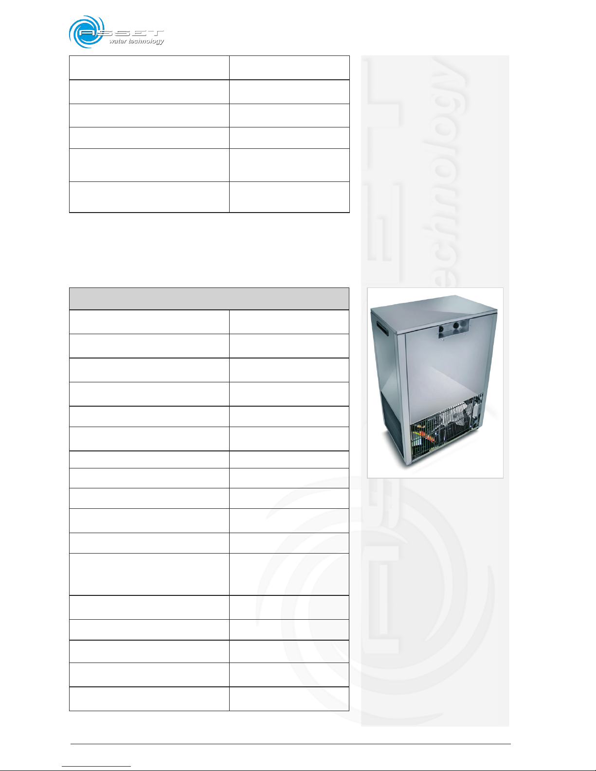
SIMULTANEOSLY DISPENSED WATERS
YES - MAX 2 waters
simultaneously
ANTY-LEAKAGE SECURITY VALVES Included
SOUND PRESSURE LEVEL 50 dB(A)
SOUND POWER LEVEL 62 dB(A)
STORAGE TEMPERATURE min/max
Min 2 °C/35,6 °F - Max 40
°C/104 °F
DRAIN PIPE FOR TANK TOO FULL Directly in the drip tray
ATLANTIS 180 US - Under Sink
UNDER SINK
ROOM WORK TEMPERATURE
220/230V 50/60Hz
monophase
MAX POWER CONSUMPTION
680W - 3,1A
Climatic Class SN
ROOM WORK TEMPERATURE 10-32 °C / 50-89,6°F
COMPRESSOR POWER 520W - 1/3 Hp
QUANTITY OF REFRIGERANT GAS R134a 180g
CONDENSATION OF VENTILATED AIR YES
WATER PUMP TYPE Rotary
CARBONATION SYSTEM Saturator
MINIMUM INLET WATER TEMPERATURE 5 °C / 41°F
MAXIMUM INLET WATER TEMPERATURE 25 °C / 77°F
DISPENSED WATER TEMPERATURE Adjustable 2÷4 °C
COLD AND SPARKLING WATER OUTPUT
180l/h ∆t = 10 °C / 50 °F
(Room Temperature 25°C /
77°F - Humidity 75%)
WATER SYSTEM WORKING PRESSUR
MIN-MAX
1.5 - 5 bar
CARBONATOR CAPACITY 2.5 l
ICE BANK TANK CAPACITY
28 l
ICE BANK 14 Kg
MIN - MAX CO2 WORKING PRESSURE 3.5 - 6 bar
Page 25
2-7
ATLANTIS - Installation, Use and Maintenance - Man cod.-02 - Rev. 02/2011
NET WEIGHT (ACCESSORIES EXCLUDED) 44 Kg
GROSS WEIGHT (ACCESSORIES EXCLUDED)
48 kg
DISPENSER DIMENSIONS LxWxH
INCLUDING DRIP TRAY
455x300x700mm
PACKAGE DIMENSIONS LxWxH 490x330x730mm
SOLENOID VALVES NO
DISPLAY NO
AUTO DOSING SYSTEM NO
OZONE SANIFICATION NO
SIMULTANEOSLY DISPENSED WATERS NO
ANTY-LEAKAGE SECURITY VALVES NO
SOUND PRESSURE LEVEL 50 dB(A)
SOUND POWER LEVEL 62 dB(A)
STORAGE TEMPERATURE min/max
Min 2 °C/35,6 °F - Max 40
°C/104 °F
DRAIN PIPE FOR TANK TOO FULL YES - Ø 8mm
RECIRCULATION CIRCUIT YES
RECIRCULATION CIRCUIT FITTINGS Quick Fitting - Ø 8mm
IN/OUT FITTING Quick Fitting - Ø 8mm
Page 26

2-8
ATLANTIS - Installation, Use and Maintenance - Man cod.-02 - Rev. 02/2011
2.3 Emission of machine noise
The noise level with continuous operation is less than 70
dB(A). These data are available in the Technical File in
the Manufacturer’s archive.
Page 27
3-1
ATLANTIS - Installation, Use and Maintenance - cod. Man-02 - Rev. 02/2011
3.1 General notes
The dispenser was designed and manufactured in compliance with the requirements of the Machinery Directive
2006/42/EC, taking into account its ordinary use and the
reasonably intended use.
The dispenser was manufactured for the application
mentioned in the declaration of conformity enclosed to
this manual.
It is not allowed for any reason to use it for purposes
different that those for which it was designed, or to use
it with modalities different than those indicated in this
manual. The different interventions must be carried out
in accordance with the criteria and the order described
in this manual.
3.2 Symbols
Some operations are indicated in this manual by graphical symbols that recall attention on the hazardousness of
the operations. The symbols are positioned on the lateral
column, as shown in this page.
3. Safety requirements
WARNING
Before carrying out any operation
on the machine it is necessary to read the whole manual
thoroughly, paying special attention to this chapter.
WARNING
This symbol indicates the possibility that an event occurs that can
cause serious injury or considerable
damage to the machine, if suitable
precautionary countermeasures
are not adopted.
CAUTION
This symbol indicates the possibility
that an event occurs that
could cause minor injury or m
terial damage to the machine, if
suitable precautionary countermeasures are not adopted.
IMPORTANT
This symbol indicates the possibilitythat an event occurs that could
causeminor injury or material damageto
the machine, if suitableprecautionary
countermeasures arenot adopted..
Page 28

3-2
ATLANTIS - Installation, Use and Maintenance- cod. Man-02 - Rev. 02/2011
3.3 Safety warnings
• Please, read carefully this instruction manual before using
the dispenser in order to be sure that it is used in the
best safety conditions.
• This device is not intended to be used by persons
(included children) with reduced physical, sensory
abilities or with scarce experience and knowledge,
unless they are under supervision of a person in
charge of their safety or they are informed by him/
her on the use of the device. It is necessary to keep
children under control to prevent them from playing
with the device.
• The repair of the product must be carried out only by
a skilled technician or in a Service Centre authorized
by Asset srl, for your security and in compliance with
the standards.
• Install the water dispenser in a proper way to guarantee a right ventilation for the machine cooling or
a distance – on all sides – of at least 15 cm from
any wall or object.
• In case of abnormal functioning do not manipulate or
tamper with the internal components of the dispenser.
Contact our technical assistance service.
• Keep this instruction manual in order to deliver it to
the new owner if the dispenser is sold.
• Do not place objects on the water dispenser.
• Do not place the dispenser upon other objects.
• In case of damage, contact the technical assistance.
• In case of breakdown, disconnect the power supply,
close the water mains and contact the technical assistance.
Page 29

3-3
ATLANTIS - Installation, Use and Maintenance - cod. Man-02 - Rev. 02/2011
• Interventions not specified in this manual must be
carried out only by skilled staff or in one of Asset’s
authorized Service Centres.
• This device is not intended to be used outdoors in the
rain and/or snow
3.3.1 Operator’s qualification
The operator must follow the instructions supplied for his
own safety and for users, in particular he must respect
the requirements contained in this manual during the
operating phases.
Typical activities foreseen:
• use of the machine and its normal operating conditions
and restoring of the operation after a stop;
• taking the necessary measures to maintain the performance quality;
• nozzle cleaning;
• water dispenser sanitization;
• collaboration with the staff in charge of the extraordinary
maintenance operations (“skilled technician”).
Page 30

3-4
ATLANTIS - Installation, Use and Maintenance- cod. Man-02 - Rev. 02/2011
Intentionally blank page
Page 31
4-1
ATLANTIS - Installation, Use and Maintenance - Man cod.-02 - Rev. 02/2011
4.1 Visual check
At the arrival the packaging shall be in perfect conditions:
- without signs of collision or breaks;
- without signs that lead to suppose that it was exposed
to heat sources, frost, water , etc.;
- without signs of tampering.
Any deformations indicate collisions that occurred during
the transport, which could compromise the normal operation of the machine.
4.1.1 Check of machine and equipment
supplied
The machine, its main body, the related accessories and
in general the equipment supplied must be in perfect
preservation conditions.
Parts included in the supply are subject to a careful control
procedure before being dispatched; however it is advisable to always check at the delivery that the material is
complete and in order.
Make sure that:
- the shipping data (address of the consignee, n° of
packages, n° of order, etc.) correspond to the data of
the accompanying documents.
- the technical-legal documentation supplied with the
machine includes the instruction manual corresponding
to the type of machine, as well as the CE declaration
of conformity.
4. Unpacking
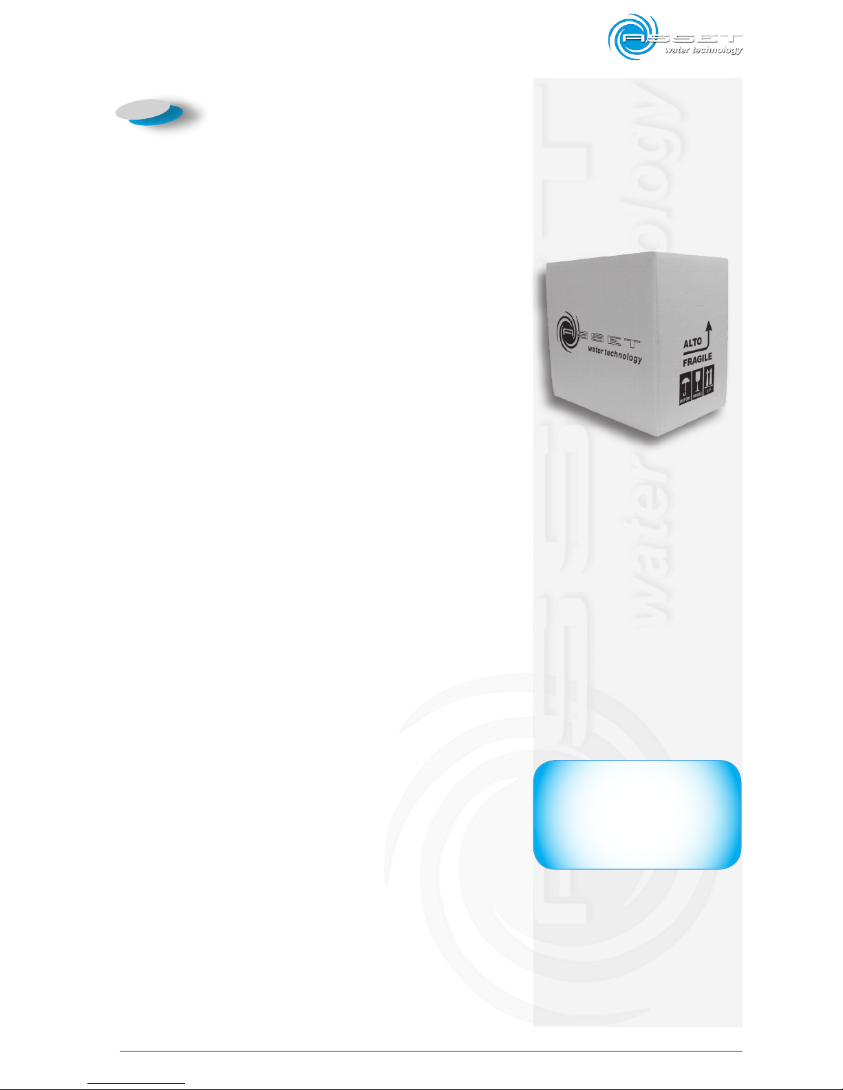
fig. 4.1
IMPORTANT
In case of defects and/or missingmat erial immedi ately communicate it to the Dealer and
follow his instructions before putting the machine into operation
Page 32
4-2
ATLANTIS - Installtion, Use and Maintenance - Man cod.-02 - Rev. 02/2011
4.2 Unpacking
Refer to the “ARROW” on the external box in order to
remove the packing material.
To remove the equipment from the packing, follow the
procedure below:
1 cut the safety plastic straps from the packing (if these
are present);
2 open the upper part of the carton box and remove
it;
3 remove the protective pluriball sheet if present;
4 analyse the equipment to check for possible damage.
Immediately inform the carrier and the Dealer if ap-
parent damage is noticed.
WARNING: Keep the packing materials in case it will
be necessary to ship again the device to the Technical
Assistance Centres!!!
4.3 Packing list
The packing list includes all the parts supplied. The
contents can change for each single machine, in accordance with the commercial agreements, with the optional
parts supplied, etc.
Indicatively the supply includes:
- water dispenser
- electric power supply cable (2m)
- water connection hose 6x8 (4m)
- 3/8” fitting for connection to the water mains
- CO2 connection hose diameter 4 mm
- n° 3 taps (Atlantis 60 e 120 Model ONLY)
- this manual
IMPORTANT
Packaging utilised comply with the
environmental requirements set by the
European packaging standards (Official
journal of the European communities,
L. N. 365/19).Carton containers are
easy to recycle. Plastic wrappings are
made with materials free from dangerousnmetals. For their disposal it is
recommended to contact the competent
Authority in the pertaining territory.
Page 33
5-1
ATLANTIS - Installation, Use and Maintenance - Man cod.-02 - Rev. 02/2011
5.1 Environmental characteristics
The operating environment must have the following
characteristics:
- Temperature: + 5 ÷ + 40 °C (41 ÷ 104 °F)
- Maximum relative humidity: 80%
The dispenser must not be used in open areas and/or
exposed to atmospheric agents or in environments with
steam, fumes or corrosive and/or abrasive dusts, with risk
of fire or explosion, and however where the use flameproof
components is required.
5.2 Cleaning
Before starting up the dispenser it could be necessary to
clean the equipment from dust, foreign substances and dirt
accumulated during the transport and storage periods.
For cleaning do not use used or dirty cloths since the
dispensing point that was sanitized before the dispatch
could be inexorably contaminated. For example, for cleaning use a new piece of blotting-paper slightly dampened
with not aggressive detergent and disinfectant products
diluted in water. Do not use solvents or alcohol-based
products. Do not touch the dispensing points with dirty
hands. The ventilation slits of the dispenser, on the right
side, must be cleaned by using a dry brush.
5.3 Positioning
The dispenser must be placed on a surface which can
support its weight including water (gross weight, see
technical sheet) or on a proper optional stand in a vertical position.
5. Installation
CAUTION
If environmental conditions different than those required are noticed
during installation, or if they change
over time, immediately contact the
Manufacturer beforeusing the dispenser for the necessary checks.
CAUTION
Do not use liquids containing
solvents or abrasive materials
to clean the dispenser.
Page 34
5-2
ATLANTIS - Installation, Use and Maintenance - Man cod.-02 - Rev. 02/2011
However, the water dispenser positioning must allow
sufficient ventilation, in particular, its back and upper
sides must have a minimum free space for ventilation
of at least of 15 cm. For this reason, the dispenser must
not be placed near direct or indirect heat sources (ex.
ovens, radiators, stoves, coffee machines, etc.).
Plugs for power and water supply must be available near
the water dispenser, and must correspond to the characteristics stated in the technical sheet and be positioned
in way that the power cable and the water hose are not
of any obstacle.
The environment, where the equipment is installed, must
be free of dust or corrosive/explosive gasses.
The location must be without vibrations.
The machine must be sufficiently illuminated in order to
correctly understand the different functions.
In case of a different positioning from the vertical one,
during the transport or installation, once in the right
position wait for at least 24 hours before getting it
started.
5.4 Connections (all models)
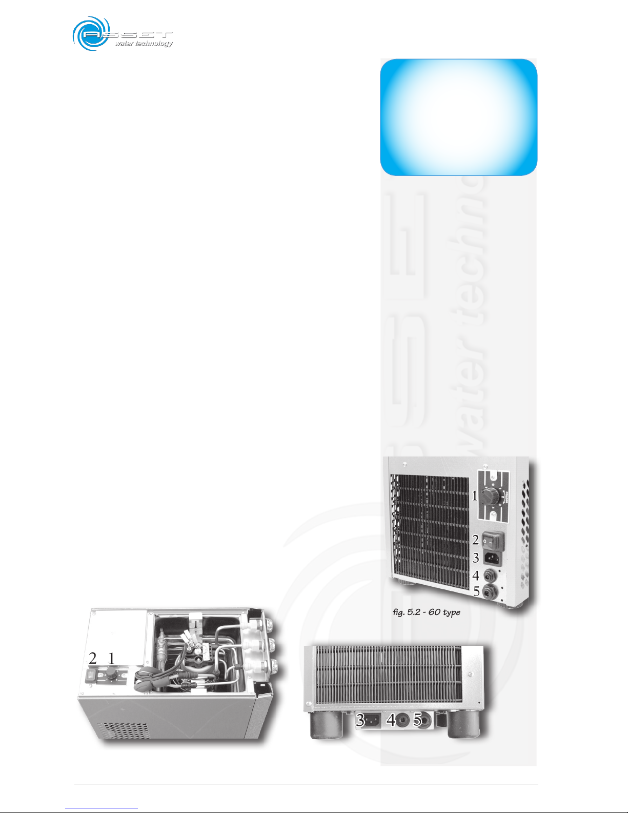
5.4.1 Outer accessories
1 Thermostat
2 main switch
3 power supply
4 CO2 gas supply
5 water supply
IMPORTANT
In accordance with UNI EN 10380
standard lighting for a generic
working area must be of 300 lux
on average (acceptable values
between 200 and 500 lux). If
the equipment is installed in a
Country different from Italy, refer
to the related regulations in force.
fig. 5.2 - 60 type
fig. 5.1a 120 type - top
fig. 5.1b 120 type - back
Page 35
5-3
ATLANTIS - Installation, Use and Maintenance - Man cod.-02 - Rev. 02/2011
5.4.2 Taps assembly
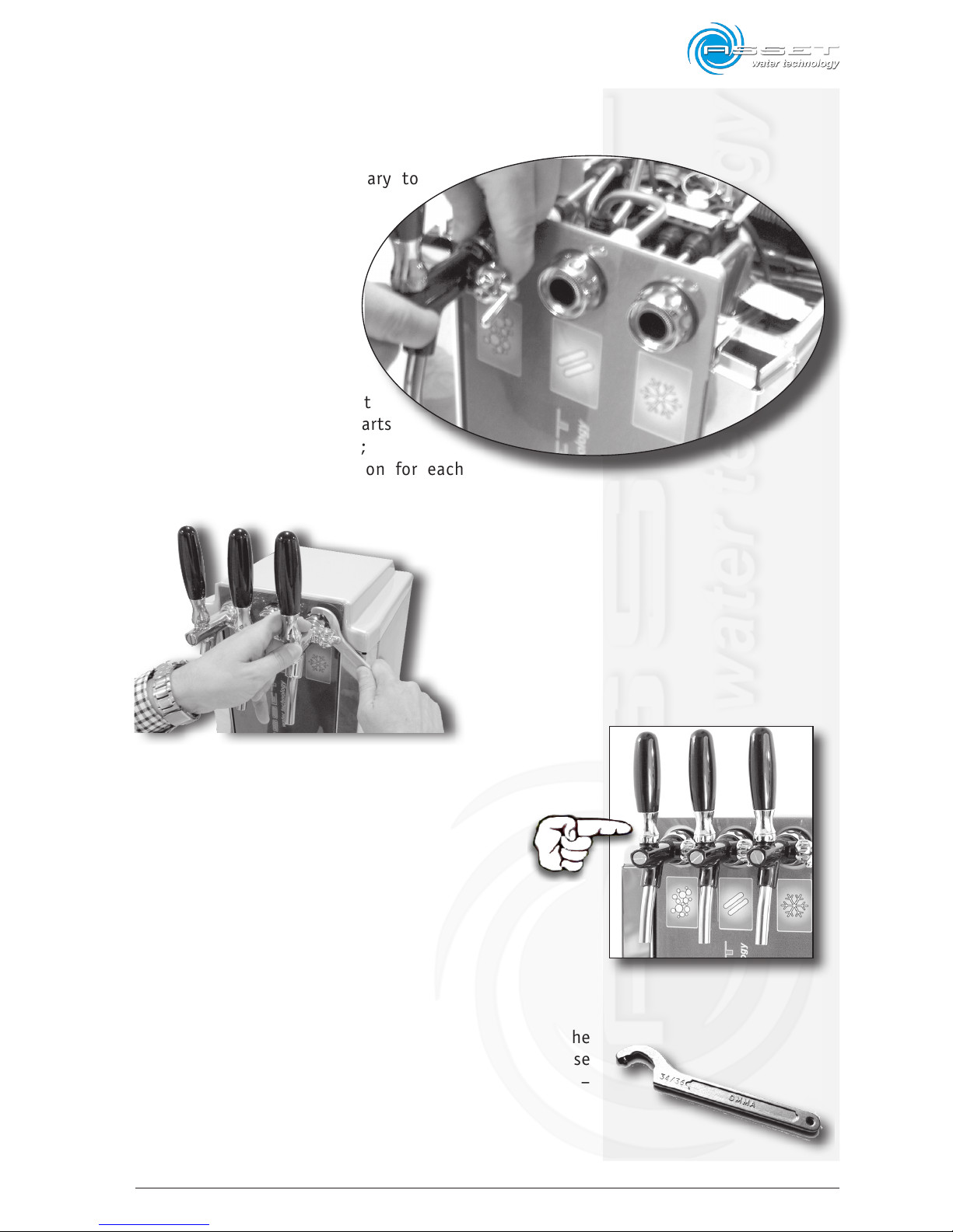
The device is supplied with disassembled
taps, therefore it is necessary to
reposition them.
Proceed as follows (see fig.
5.3):
- insert the conical part of
the tap in the tap holding
cavity already assembled
on the dispenser;
- Turn the chrome ring nut
counterclockwise screwing it
on the tap until the two parts
are completely tightened;
- Repeat the same operation for each
tap.
ATTENTION:
the three taps are NOT equal; packing list includes 2
Tap + 1 stainless steel Tap. For the sparkling water
you MUST absolutely install the stainless steel Tap.
Do not use pliers, wrenches or other tools to tighten the
ring nuts of the taps, just tighten them manually or use
the appropriate spanner supplied. (CODE M-CHIAVEXATL –
PIN WRENCH FOR ATLANTIS PRE-MIX TAPS).
fig. 5.3
fig. 5.6
fig. 5.4
fig. 5.5
Page 36
5-4
ATLANTIS - Installation, Use and Maintenance - Man cod.-02 - Rev. 02/2011
5.4.3 Water filter insertion
(optional)
Proceed as follows:
- cut the water supply tube in the insertion point of
the prefilter
- insert the supply tube, interception valve side, on
the inlet fitting of the prefilter
- insert the free end of the supply tube on the outlet
fitting of the filter
- position a suitable container at the free end of the
tube that will be inserted in the dispenser and open
the interception valve to drain and clean the tube
and the external prefilter (if assembled), drain at
least 2 l of water, after this operation close again
the interception valve.
- connect the free end of the tube to the rotary fitting
positioned on the dispenser
- open the interception valve to check that there are
no leakages from the fittings previously assembled
It is, however, compulsory to insert a filtering unit, having the specific characteristics for the device, in series
with the water supply line; the manufacturer declines any
responsibility for the consequences due to non observation of this requirement.
In any case, any filtering unit which has to be connected
to the water dispenser must be necessarily drained.
Moreover, verify that the unit agrees with the hygienic
and security standards in force and its compatibility with
the technical features of the dispenser as stated in the
previous technical sheet.
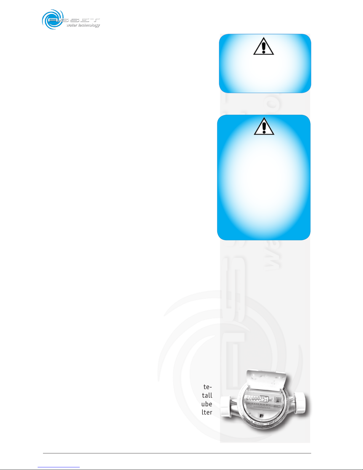
5.4.4 Insertion of the litrecounter
(optional)
In order to better check the filter life and the mainte-
nance gaps of the device, it is recommended to install
a litrecounter after the filter on the water supply tube
of the device following the same procedure for the filter
installation.
WARNING
Use specific filters that dose
anti-limescale products to prevent the formation of limescale
in the hot parts of the device.
WARNING
The Manufacturer declines any responsibility for possible damage to
persons or things due to connection of the dispenser to electrical
mains not in conformity with the
regulations and laws in force in the
country where the device will be
installed. In particular, the electric
mains must be equipped with a high
sensitivity circuit breaker switch
(cut-out switch), with tripping power
not greater than 30mA, and a grounding system in conformity with the
standards and regulations in force.
fig. 5.7
Page 37
5-5
ATLANTIS - Installation, Use and Maintenance - Man cod.-02 - Rev. 02/2011
5.4.5 Connection to the water mains
Any temporary connections are forbidden for a good functioning of the dispenser. The following operations must
be carried out by a skilled staff.
During the installation, new water supply pipes for connection to the water mains must replace the old ones that
must not be used again.
The water supply plug of the water dispenser must be
made up of an interception valve (tap) and a non-return
valve.
For a good functioning of the dispenser the water mains
must satisfy the following the characteristics:
• no overpressure;
• pressure values according with the previous technical
data sheet (see chapter 2.2).
If the pressure of the water mains is greater than 4,5 bar,
it will be necessary to install a pressure reducer after the
interception valve, by setting the pressure on 4 bar.
Fittings and pipes for connection to water mains must be
certified for food compatibility. All the pipes and fittings
provided agree with the abovementioned feature. Optional
accessories such as filters, pre-filters, to be assembled
on the water mains after the interception valve, must be
certified for food compatibility.
For a correct installation to the water mains, proceed as
follows:
1. screw the non-return valve on the interception valve,
the pressure reducer if necessary and the 3/8” x 8 fitting in order to connect the water supply tube included
in the supply
2. connect the supply tube to the water supply fitting
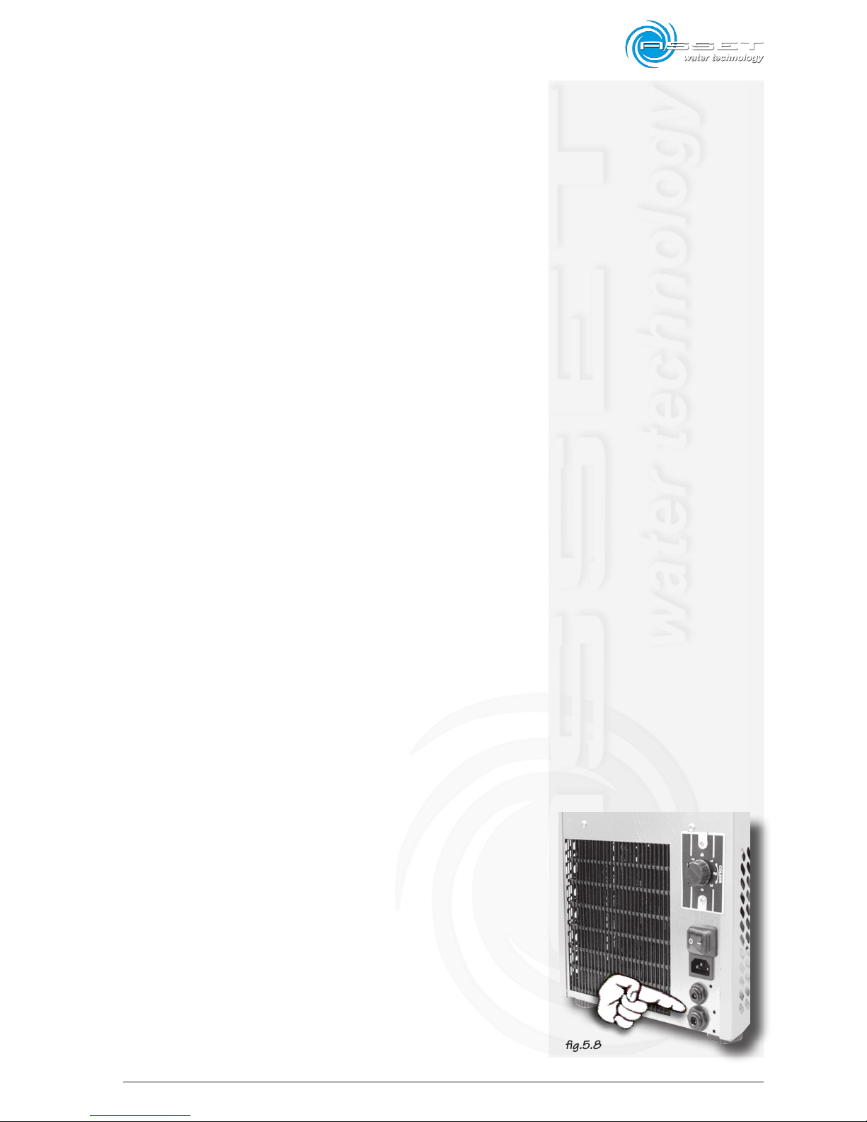
(fig. 5.8)
3. position a suitable container at the free end of the tube
to be inserted in the dispenser and open the interception valve to drain and clean the tube, the external
filter and the outer accessories (if any) by draining
at least 5 l of water, after this operation close again
the interception valve
fig.5.8
Page 38
5-6
ATLANTIS - Installation, Use and Maintenance - Man cod.-02 - Rev. 02/2011
4. connect the free end of the tube to the water inlet
fitting positioned on the back side of the dispenser
5. open the interception valve to check that there are
no leakages from the fittings previously assembled.
6. It is suggested to carry out the dispenser sanitization
by using the appropriate kit (optional and not supplied
with the dispenser)
Water supply connections with a length longer than 4-5
metres must be realized with a greater section pipe. The
pipe delivered with the supply will be used just for the
connection to the water dispenser and to the optional accessories (filters, prefilters, etc.) which must be installed
in line with the mains.
5.4.6 Power supply connection
The dispenser is in accordance with the current EEC norms.
For this reason, it is marked with the CE symbol.
The Manufacturer declines any responsibility for possible
damage to persons or things due to connection of the
dispenser to electrical mains not in conformity with the
regulations and laws in force in the country where the
device will be installed. In particular, the electric mains
must be equipped with a high sensitivity circuit breaker
switch (cut-out switch), with tripping power not greater
than 30mA, and a grounding system in conformity with
the standards and regulations in force.
Anyway, it will be necessary to check that characteristics
of the power supply line are suitable for the dispenser,
as indicated in the technical data sheet.
In case the power supply cable is damaged, it must be replaced with a new one having the same characteristics.
Any attempt to repair the cable is forbidden!
After the required checks, it will be possible to insert the
female plug with trapezoidal section of the power cable
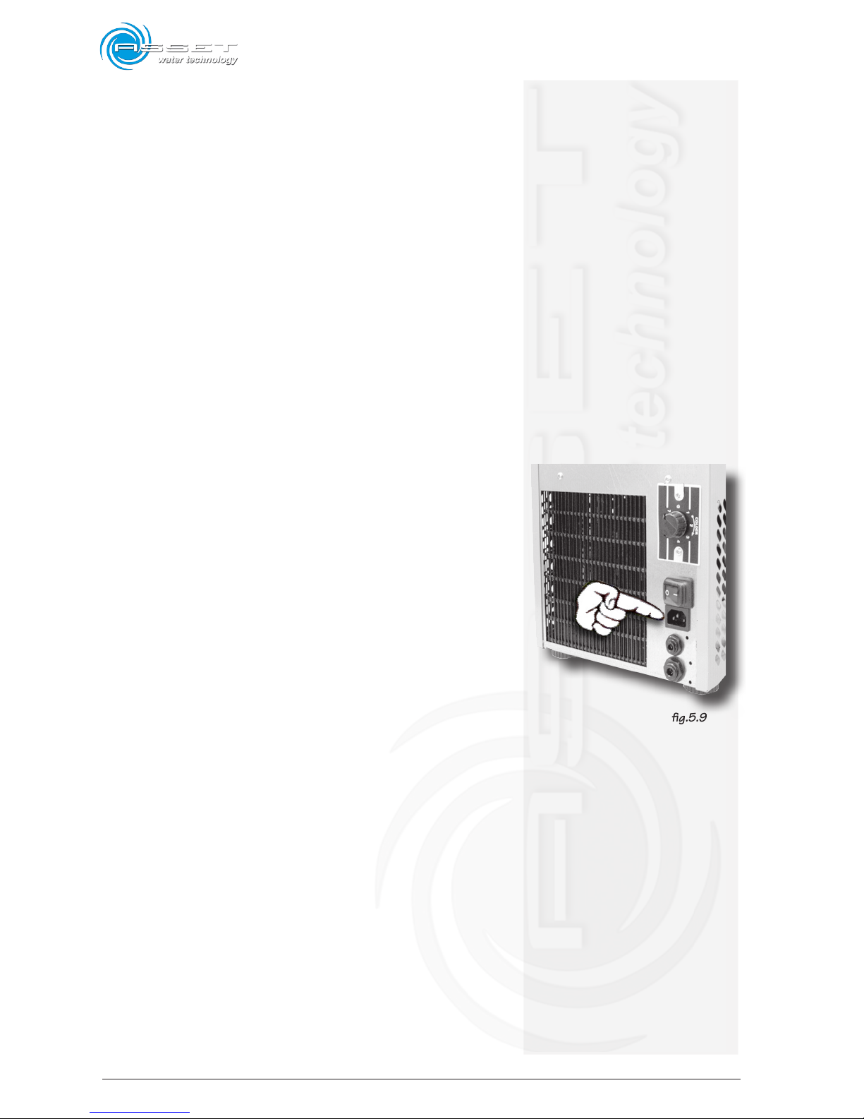
in the proper socket, in the back side of the dispenser
(fig. 5.9).
fig.5.9
Page 39
5-7
ATLANTIS - Installation, Use and Maintenance - Man cod.-02 - Rev. 02/2011
Before inserting the power connection plug of the dispenser
in the socket, make sure that the main switch is positioned
on O (see photo) and then open the water interception
valve and the CO2 bottle, fill the ice bank tank up to the
level indicated (see fig. 4) and follow the instructions
included in the paragraph First Start-up.
5.4.7 Connection of the CO
2
Arrange the CO2 gas line by using the proper plastic tube
with a diameter of 4 mm.
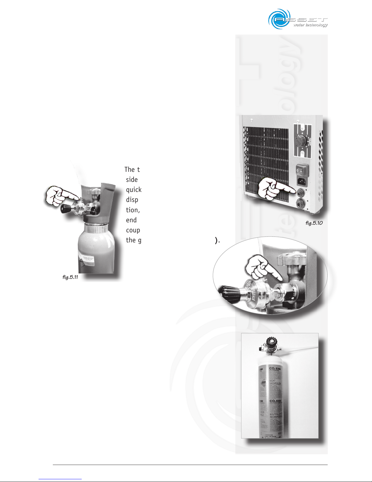
The tube has to be inserted on one
side (see fig. 5.10) in the proper
quick coupling placed behind the
dispenser above the water connection, and the other end of the tube
end has to be inserted into the quick
coupling of the pressure reducer of
the gas bottle. (see fig. 5.11).
Screw the pressure reducer on the gas bottle with a proper
spanner (28mm) if a rechargeable bottle is used (fig. 5.12); in
case a 600gr. single-use gas bottle is used, screw the reducer
on the bottle by hand. (fig. 5.13).
Pay attention to do not lay the bottle during the pressure
reducer screwing phase. Position and fix the bottle in vertical position.
fig.5.10
fig.5.11
fig.5.12
fig.5.13
Page 40
5-8
ATLANTIS - Installation, Use and Maintenance - Man cod.-02 - Rev. 02/2011
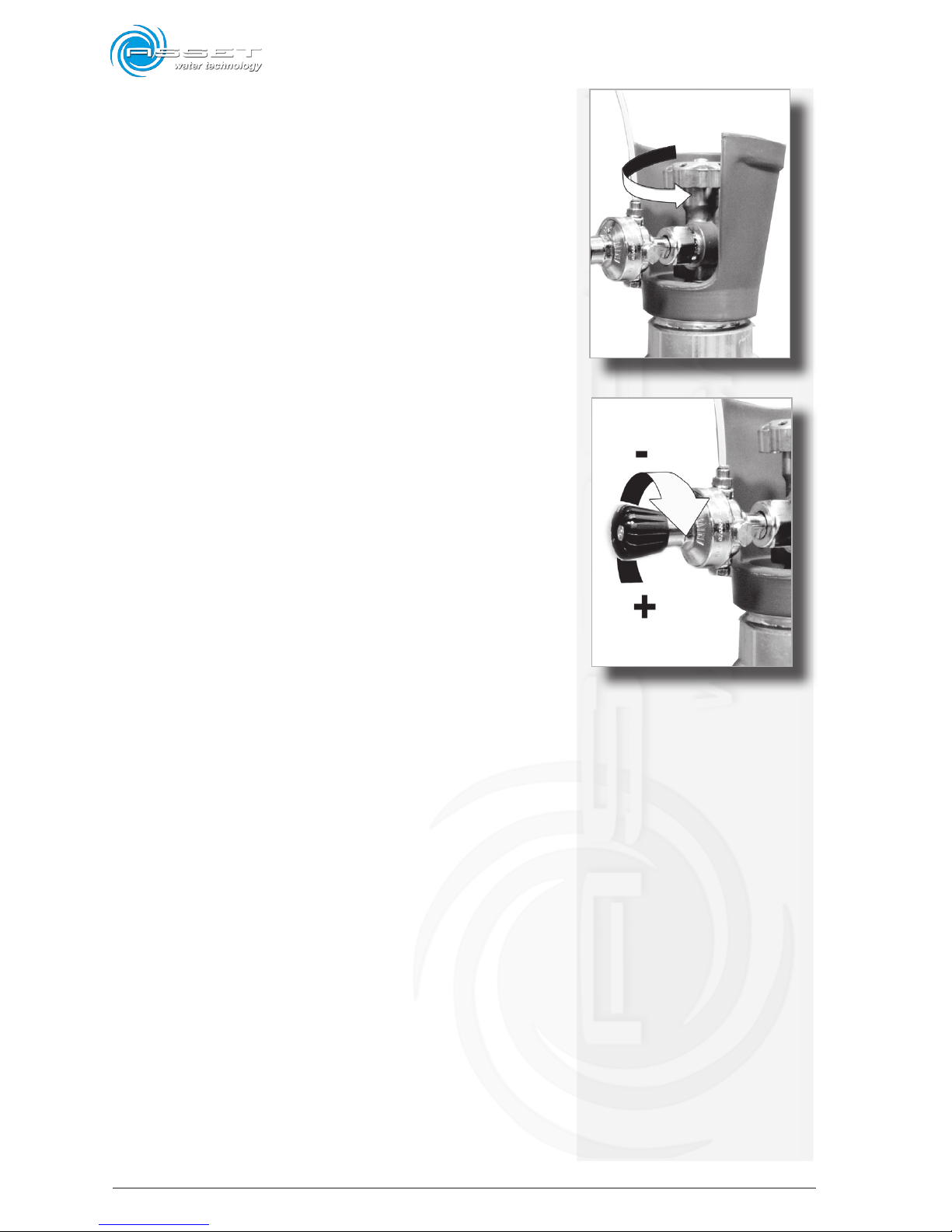
Open the (rechargeable) gas bottle by turning the upper
handgrip counterclockwise (fig. 5.14).
Turn clockwise the black knob of the pressure reducer
(screwing deeply towards the + sign) and check that there
are no leakages on the connection points by using soapsuds
water (fig. 5.15).
fig.5.15
fig.5.14
Page 41
6-1
ATLANTIS - Installation, Use and Maintenance - Man cod.-02 - Rev. 02/2011
6.1 Control panel
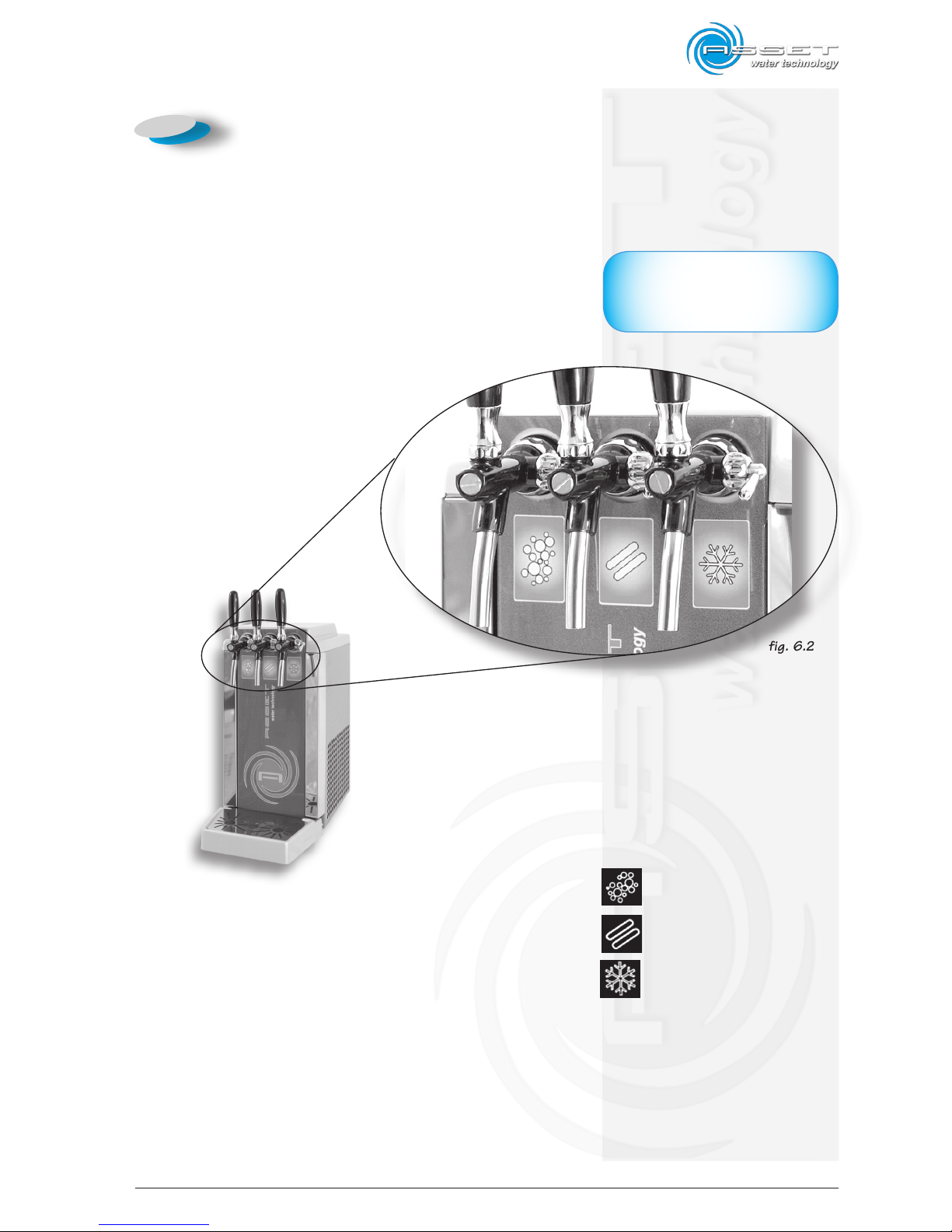
Atlantis 60 and 120 models are professional water dispensers with three hand tap dispensing points equipped
with manually-adjustable flow regulator.
Dispensing taps are identified by a symbol impressed on
the front panel that indicates the type of water
dispensed:
1 cold sparkling water dispensing
2 room temperature still water dispensing
3 cold still water dispensing
IMPORTANT
The picture shows the position of
the controls on a standard machine.
fig. 6.2
fig. 6.1
6. Dispenser use
Page 42
6-2
ATLANTIS - Installation, Use and Maintenance - Man cod.-02 - Rev. 02/2011
6.2 First start up (all models)
After the carrying out all the operations described in
chapter 5, proceed as follows:
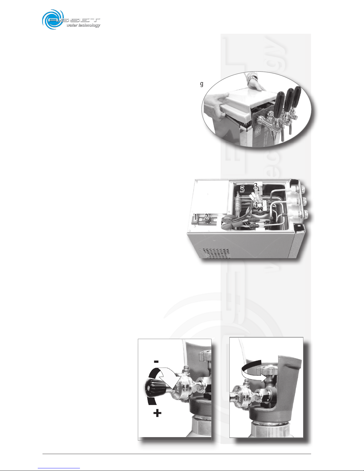
1 lift the upper plastic cover of the device pulling
it up;
2 fill the ice bank tank (point 5) with clean
water using a bucket or a carafe paying
great attention to prevent wetting the
electrical parts (thermostat and general
switch for model Atlantis 120);
3 fill the tank up to the arrow that indicates
the maximum level (see point 3), do not
fill the tank excessively. After filling the
device it must not be moved from its position. Any movement of the device could
make water outcome from the ice bank causing great
risks for the person handling or using the dispenser;
4 dry any splashes or drops that are out of the tank
5 open the CO2 gas by operating the tap on the bottle
and adjusting the pressure
reducer by turning the knob
clockwise;
fig. 6.3
fig. 6.4
fig. 6.5
fig. 6.6
Page 43
6-3
ATLANTIS - Installation, Use and Maintenance - Man cod.-02 - Rev. 02/2011
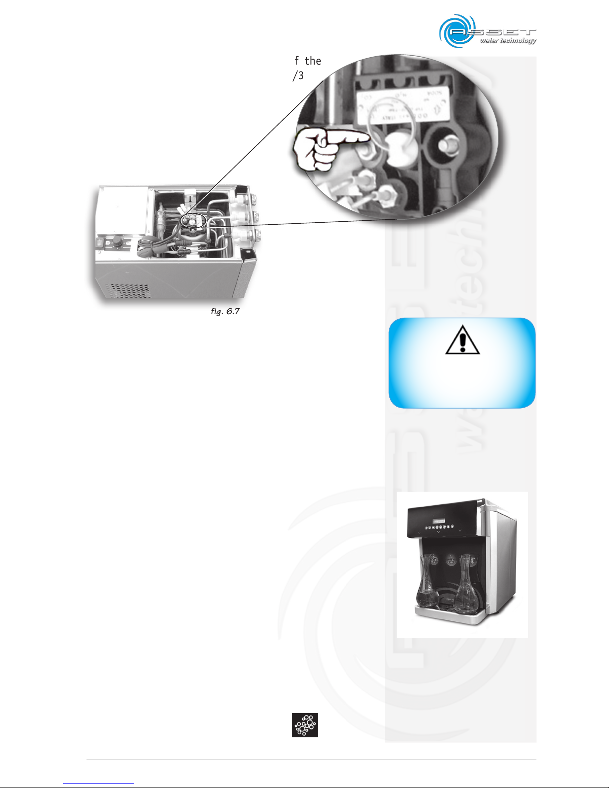
6 Pull the ring of the safety valve of the
carbonator purging gas for at least 2/3
seconds (see at side);
7 Open the water interception tap;
8 Check that they are no leakages on the internal and
external fittings of the device and near the tube connection points;
9 Place a container, with a capacity of at least 5 litres,
under the dispensing taps;
10 dispense at lest 3/4 litres of room temperature still
water;
11 dispense at lest 3/4 litres of cold still water;
12 Insert the power connection plug and position the
switch on 1 (on) to start the device (point 1);
13 Position the thermostat knob on number 7 (point 2);
14 Wait 2/3 minutes;
15 Position the container under the left
dispensing
WARNING
if the device is operated without
water in the ice bank it will cause
serious damage to the device.
fig. 6.7
fig. 6.8
ATLANTIS 180 Touch TT (Table Top)
Page 44
6-4
ATLANTIS - Installation, Use and Maintenance - Man cod.-02 - Rev. 02/2011
tap (cold sparkling water), pull the lever (if Touch
Models press the key) and dispense water until gas
comes out;
16 Close the upper plastic cover, fitting it in its
seat, and wait about 90/120 minutes before
dispensing water again in order to allow the ice
bank formation;
17 Once started the device, it must be left operat-
ing permanently. If electric supply is interrupted for
more than 2/3 hours it could cause an alteration to
the ice bank thickness with consequent freezing of
the water coil.;
18 In case a similar anomaly occurs, follow the procedure
described in paragraph “Ice bank defrosting”.
6.3 Temperature setting
Atlantis 60, 120 and 180 are professional water dispensers equipped with ice bank refrigerating system
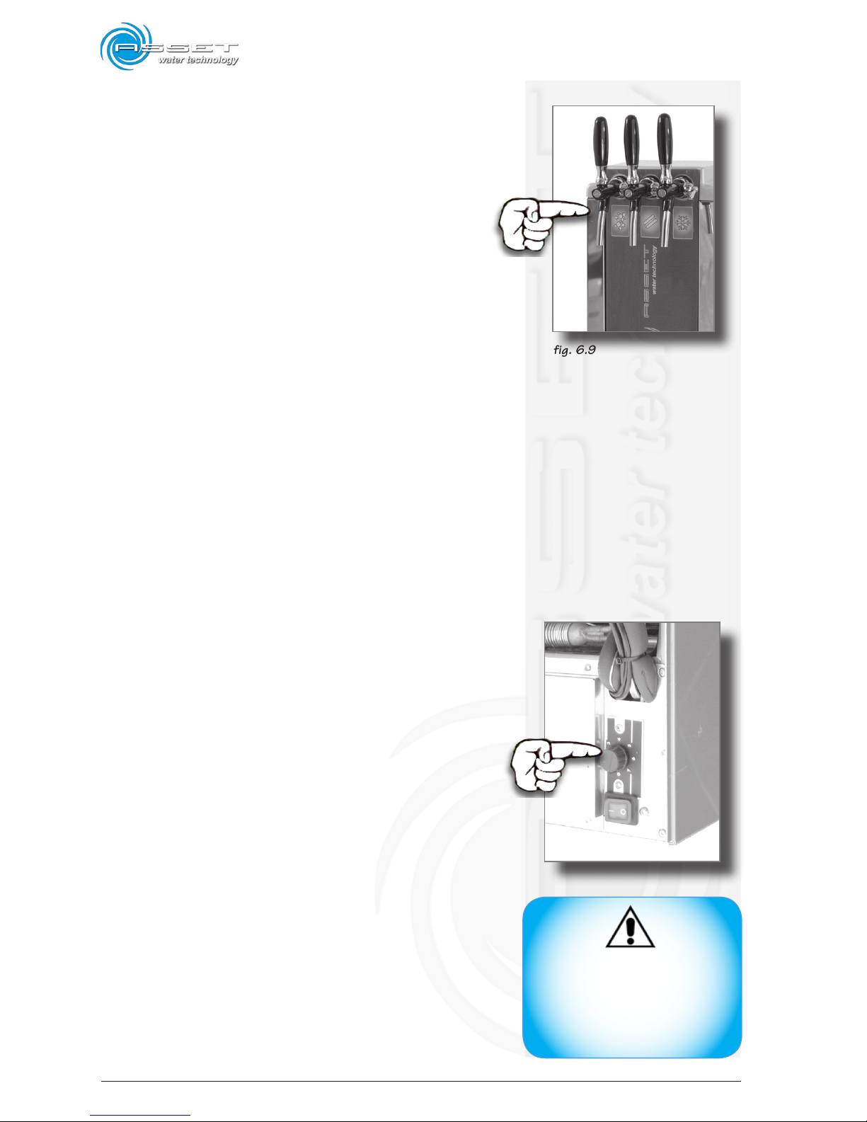
controlled by a thermostat (see fig. 6.10).
The thermostat setting adjusts the water temperature
and the quantity of ice inside the tank; the minimum
water temperature and the maximum cold water
dispensing capacity is achieved by positioning the
thermostat on number 6 and 7.
By positioning the thermostat from 1 to 5, the
water temperature will be higher and the capacity
of dispensing cold water is reduced.
WARNING
Do not remove water from the
ice bank by tilting the device;
water could penetrate in the
electrical parts causing serious damage to the device.
fig. 6.9
fig. 6.10
Page 45
6-5
ATLANTIS - Installation, Use and Maintenance - Man cod.-02 - Rev. 02/2011
6.4 Ice bank defrosting
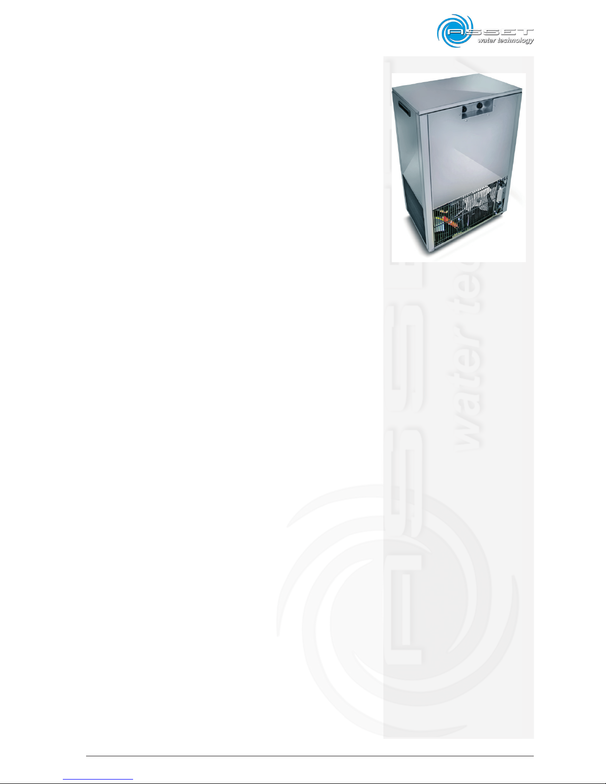
Lift the upper cover of the device (Atlantis 120 model),
turn the knob of the thermostat on 0 and leave the switch
on 1 (on).
Close the cover and frequently dispense cold water from
the right tap.
The device must be power supplied at least for 12 - 24
hours.
Lift again the upper plastic cover and check that there
is no ice.
Set the thermostat on 6 or 7 and wait at least 90/120
minutes to restore the ice bank.
6.5 Ice bank emptying and ice
bank water replacement
It is necessary to replace water in the ice bank yearly
proceeding as follows:
- after carrying out the defrosting phase, (paragraph
6.4), close water, CO2 gas and remove the power
connection plug;
- make available a rubber tube long 2 metres;
- insert the end of the tube to the bottom of the ice
bank tank and suck water by the siphon letting it
flow in an underneath container until the ice bank
is completely emptied.
ATLANTIS 180 US (Under Sink)
Page 46
6-6
ATLANTIS - Installation, Use and Maintenance - Man cod.-02 - Rev. 02/2011
6.6 Touch screen user interface
Atlantis 60, 120 and 180 Touch TT (Table Top) models
are professional water dispensers with three dispensing
points equipped with touch screen keypad and electronic
display.
The touch screen keypad technology is by now applied on
many house appliances and consumer devices that we
commonly use, the absence of mechanical moving parts
makes this system robust, no-wear, water-proof and
hygiene features thanks to the absence of interstices
where dirt and bacteria can accumulate.
For a correct use of the touch screen keypad touch the key
in a decisive way with the finger. If the finger touches the
key slowly or laterally, the key will not consider it valid and
therefore the dispensing will not occur.
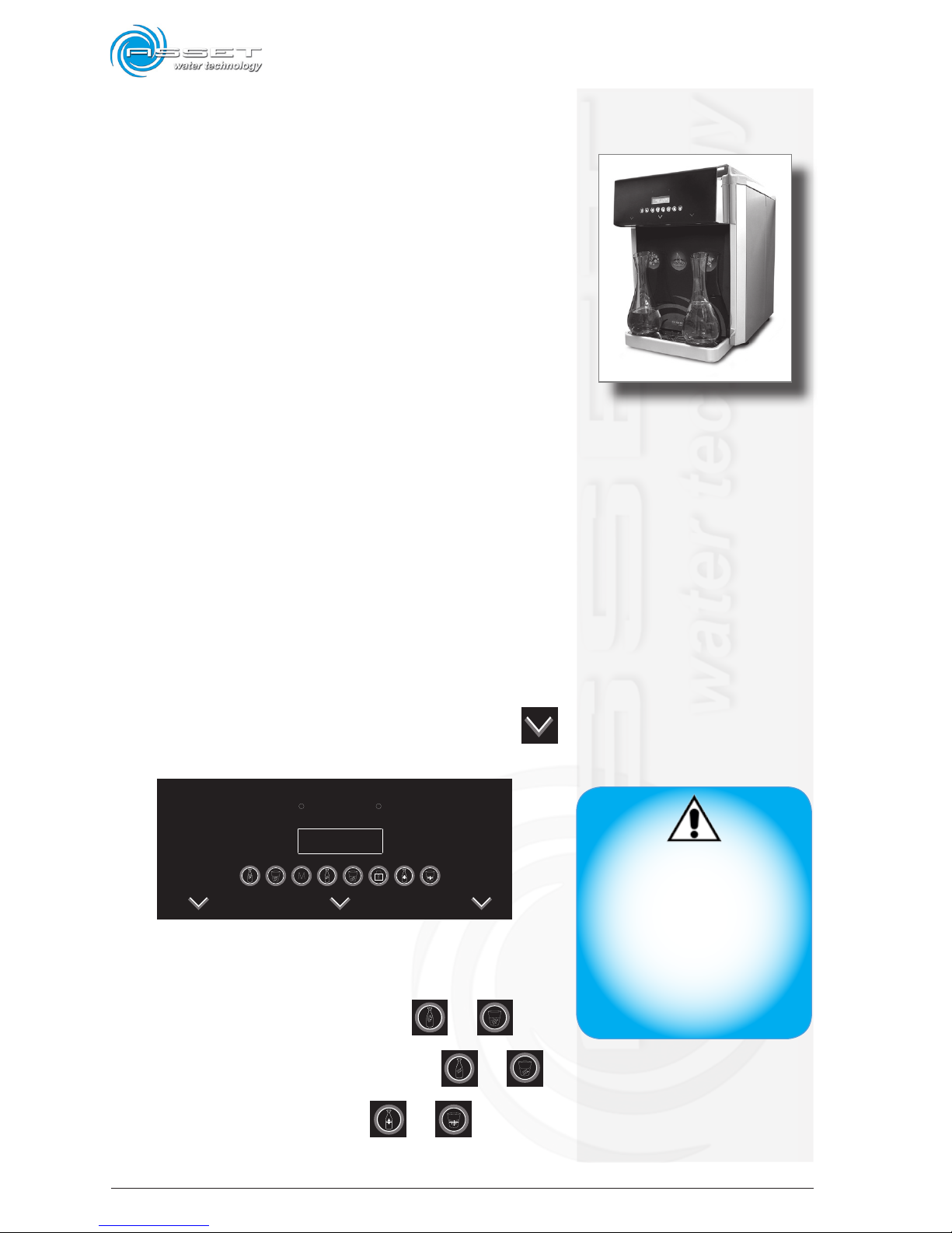
The touch keys for dispensing, keypad lock, anomaly led
and display are positioned on the front part of the dispenser. (see at side). During standard operation (Energy
Saving set to 2) the display is on and illuminated with
blue light and the dispensing keys are off; when any keys
is touched they all illuminate immediately with white
light without dispensing.
The 3 dispensing points are identified by a symbol
impressed on the front panel.
1 2 3
1 cold sparkling water dispensing: or
2 room temperature water dispensing: or
3 cold still water dispensing: or
CAUTION
When electric power is supplied
to the dispenser the touch screen
keypad carries out a self-setting,
to prevent false settings, before
powering the dispenser, clear the
keypad from any objects, cloths
or other objects placed on it and
wait 3 seconds after powering
the device before touching the
keypad. with fingers.
ATLANTIS 180 Touch TT (Table Top)
Page 47
6-7
ATLANTIS - Installation, Use and Maintenance - Man cod.-02 - Rev. 02/2011
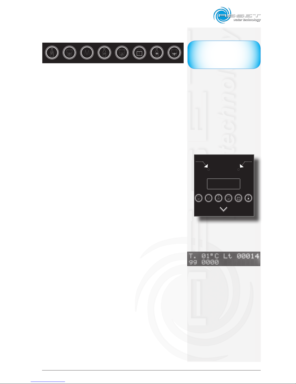
The symbols on the control keypad refer to the following
functions:
1 2 3 4 5 6 7 8
1 - Cold sparkling water dispensing (Bottle - Fisrt Dosing)
2 - Cold sparkling water dispensing (Glass - Second Dosing)
3 - Save Dosing
4 - Room temperature water dispensing (Bottle - Fisrt Dosing)
5 - Room temperature water dispensing (Glass - Second Dosing)
6 - Keyboard lock / Menu Access Key
7 - Cold still water dispensing (Bottle - Fisrt Dosing)
8 - Cold still water dispensing (Glass - Second Dosing)
6.7 Anomalies Signalling Led
Above the display there are two leds that indicate possible
failures which illuminate with fixed or intermittent light in
accordance with the problem to signal (fig. 6.11).
Led 1 at left above the dispensing key is for the filter prealarm and blockage for exhausted filter.
Led 2 at right above the key indicates the alarms with codes
and short description (see DIAGNOSTICS chapter).
6.8 Touch Models Display
In standard operating conditions the display shows the
manufacturer’s or dealer’s information, the data related to
water temperature inside the dispenser, dispensed litres,
filter days of use and gas (CO2) pressure in bar (optional) are
displayed pressing any dispensing key.
NB: The dispensed litres counter is updated after several
dispensing operations therefore the value displayed must
never be considered as absolute value, this is true also
for the days of use.
The display shows also the possible alarms signalled by the
Led 2 positioned above the display, the message includes
also the alarm code and the partial description of the alarm.
The alarms are displayed by pressing any dispensing key.
fig. 6.11
Led 1 Led2
IMPORTANT
The pictures shows the position of
the controls on a standard machine.
Page 48
6-8
ATLANTIS - Installation, Use and Maintenance - Man cod.-02 - Rev. 02/2011
6.9 Water Temperature Adjustment
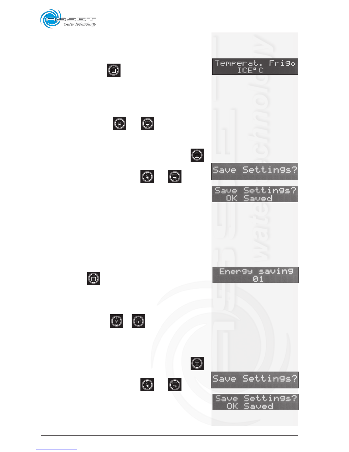
1. The User Menu is accessed by pressing the front
Menu Access Key for at least 3 seconds - or
until the beep is heard; (same key must be used to
scroll between the Menu sections).
2. the [REFRIG. TEMP] message is displayed (default value
=ICE°C)
3. by operating on the and keys is possible
to change the Temperature among 2°- 4°C , or to
ICE°C (default) or to OFF.
4. when the desired value is set, press the key
until the [SAVE SETTINGS?] message is displayed;
5. press simultaneously the keys and to save
the settings; the [OK SAVED] message should be
displayed followed by a confirming beep, after few
seconds the display will shown the home screen.
6.10 Energy Saving Function
1. The User Menu is accessed by pressing the front Menu
Access Key for at least 3 seconds - or until the
beep is heard;
2. press again the rear menu key until the [ENERGY
SAVING] message is displayed;
3. by operating on the or keys it is possible to
change the function choosing “0” (all keys backlight
ON) disabled or “1” (all keys backlight intermittent
flash) or “2” (all keys backlight OFF) enabled;
4. when the desired value is set, press the key
until the [SAVE SETTINGS?] message is displayed;
5. press simultaneously the keys and to save
the settings; the [OK SAVED] message should be
displayed followed by a confirming beep, after few
seconds the display will shown the home screen.
Page 49
6-9
ATLANTIS - Installation, Use and Maintenance - Man cod.-02 - Rev. 02/2011
When the Energy Saving function is set to “0” (that means
that the Energy Saving function is disabled) all the keys
backlight are illuminated.
When the Energy Saving function is set to “1” (that means
that the Energy Saving function is enabled) all the keys
backlight intermittent flash.
When the Energy Saving function is set to “2” (that means
that the Energy Saving function is enabled) all the keys
backlight are off but - when keys are touched - they illuminate immediately without dispensing; it starts dispenses
when the key related to the desired water type is touched.
NB: The system returns to the energy saving function 120
seconds after the last dispensing.
6.11 Automatic Water Dispensing
Dosage
This option allows to dose the water automatic dispensing 2 different quantity of water for every type of water
available from the dispenser.
On the fron panel there are 2 keys for each type of dispensed water; first key shows a bottle while the second
key shows a glass.
ATTENTION: In all dispensers the automatic timed water dispensing program is not enabled for default and
therefore – if desired – it is necessary to enable it.
Once enabled, it will be possible to press one time only the
related key to dispense the memorized quantity of water.
It’s possible to dispense a different quantity of water by
simply keep pressed the related keys.
The dispensed litres counter is updated after several dispensing operations therefore the value displayed must
never be considered as absolute value.
ATTENTION: if you are planning to use this feature we
strongly racommend to install a pressure reducer; it’s
also considered a normal behavior to have about 10-15ml
of difference between each consecutive dispensed dose.
ATTENTION
In all dispensers the automatic
timed water dispensing program is not enabled for default
and therefore – if desired –
it is necessary to enable it.
Page 50
6-10
ATLANTIS - Installation, Use and Maintenance - Man cod.-02 - Rev. 02/2011
To enable it, proceed as follows:
1. The User Menu is accessed by pressing the front Menu
Access Key for at least 3 seconds - or until the
beep is heard;
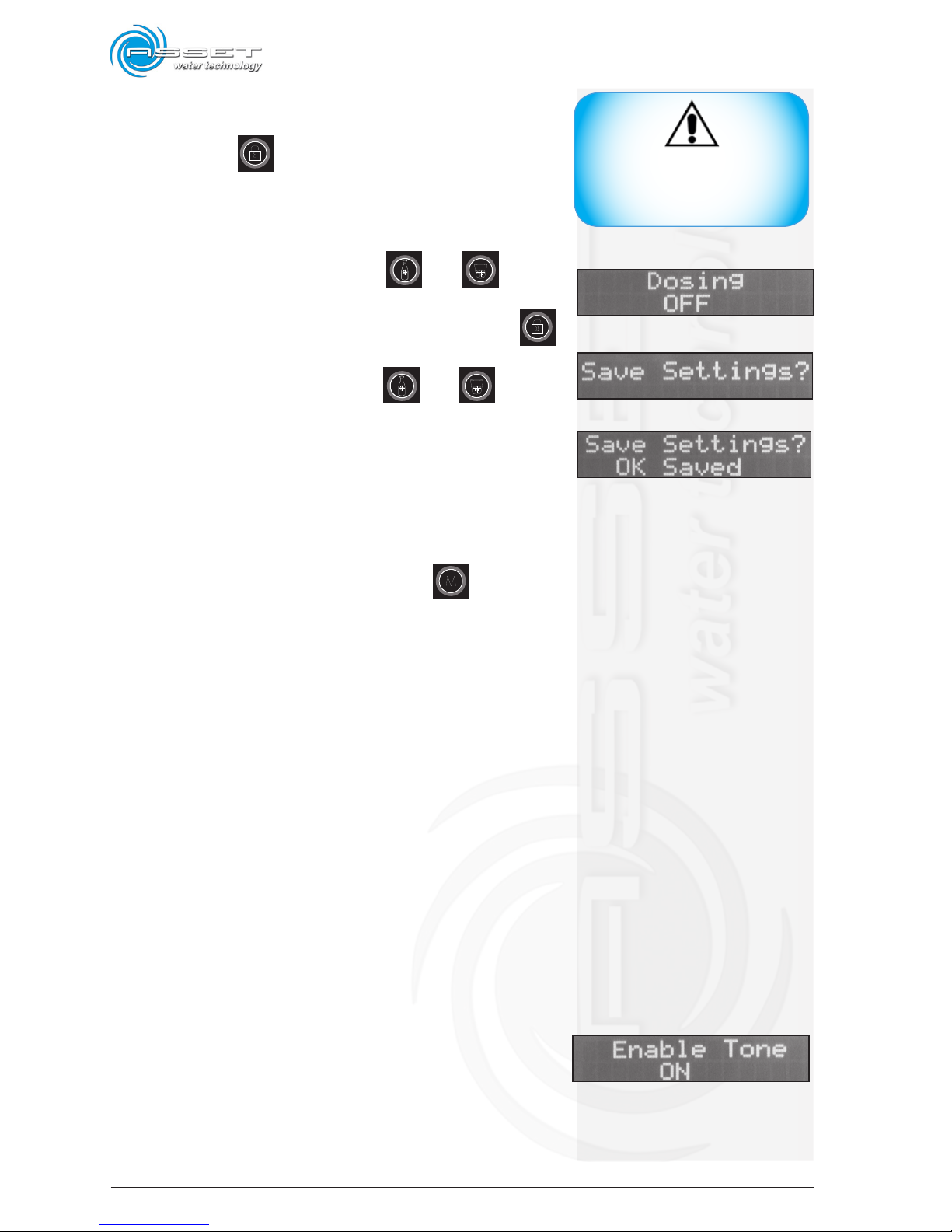
2. press again the rear menu key until the [DOSING]
message is displayed. Factory default value is set
to [OFF]; by operating on the and keys it
is possible to change the function choosing “ON”.
3. when the desired value is set, press the key
until the [SAVE SETTINGS?] message is displayed;
4. press simultaneously the keys and to save
the settings; the [OK SAVED] message should be
displayed followed by a confirming beep, after few
seconds the display will shown the home screen.
Now the dispenser is ready to receive the automatic dosing
settings for timed water dispensing for the single avai-
lable waters; press the Save Dosing key for 5 sec.
Now press the desired key (it will become red) and dispense the desired quantity of water and this value will
be automatically saved when the key is released.
Repeat the same operation for all the available types of
water.
Repeat this procedure every time it is necessary to change
the quantity of automatically dosed water dispensing.
ATTENTION: To stop unintentional dispensing just press
any key !!! It’s possible to dispense a different quantity of water by simply keep pressed the related keys.
6.12 Enable Tone
The Enable Tone function allows to enable/disable any
acustic notification everytime a key is pressed.
ATTENTION
To stop unintentional dispensing just press any key !!!
Page 51
6-11
ATLANTIS - Installation, Use and Maintenance - Man cod.-02 - Rev. 02/2011
6.13 Keybord Lock
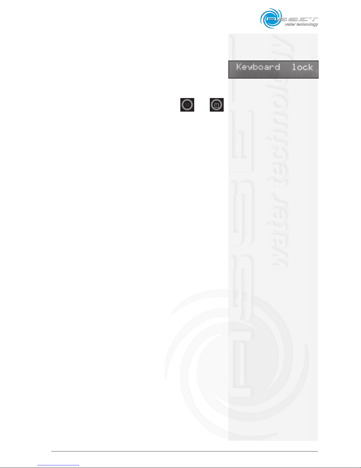
The Keyboard Lock function allows to momentarily stop the
dispensing function preventing unintentional dispensing
and allowing to clean the keyboard without necessarily
disconnecting power supply to the dispenser.
To enable the keyboard lock press the key and
for at least 3-4 seconds; when the key illuminates with red
light followed by a beep the function is active, [KEYBOARD
LOCK] will appear on the display.
To disable the function press again the key for at least
3-4 seconds until the keys turns off followed by a beep.
6.14 Eco-Save Reset
NOT IMPLEMENTED YET
6.15 Optical Sensor Presence 1 and 2
NOT IMPLEMENTED YET
6.16 Optical Sensor Setting 1 and 2
NOT IMPLEMENTED YET
6.17 Sanification Alarm
NOT IMPLEMENTED YET
Page 52
6-12
ATLANTIS - Installation, Use and Maintenance - Man cod.-02 - Rev. 02/2011
6.18 Dedicated Litre Counter
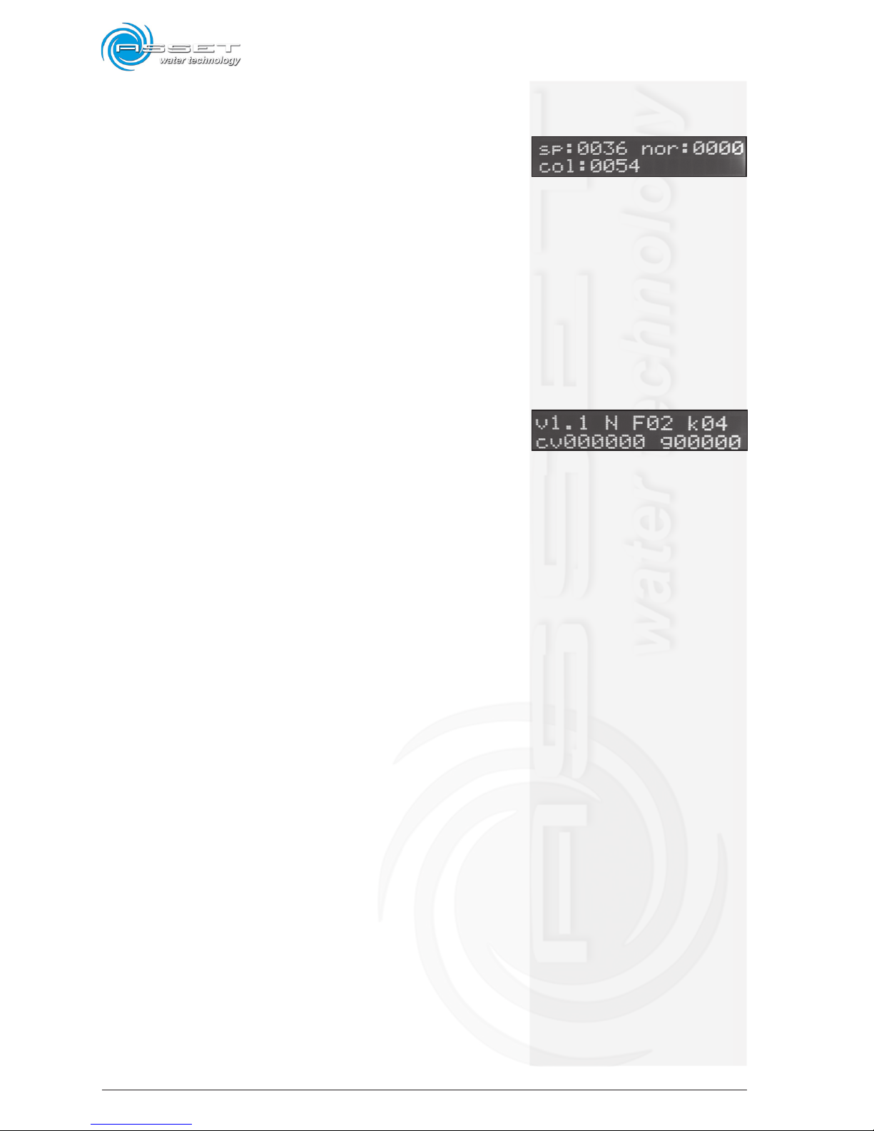
ATTENTION: Dedicated Litre Counter function ONLY works
if you have first enabled the Automatic Dispensing
Water Dosage [DOSING] Function.
Display will then show the total amount (expressed in
litres) of the dispensed water, divided by typologies.
• sp=sparkling water dispensed litres
• nor=room temperature dispensed litres
• col=cold still water dispensed litres
6.19 Firmware Version
This Menu section describes the Firmware version currentry
installed, the Filter Type an the optional Merchant Code.
• v=firmware version
• F=installed filter type
• cv=merchant code
• g=not implemented yet
Page 53

6-13
ATLANTIS - Installation, Use and Maintenance - Man cod.-02 - Rev. 02/2011
Intentionally blank page
Page 54

6-14
ATLANTIS - Installation, Use and Maintenance - Man cod.-02 - Rev. 02/2011
Intentionally blank page
Page 55
7-1
ATLANTIS - Installation, Use and Maintenance - Man cod.-02 - Rev. 02/2011
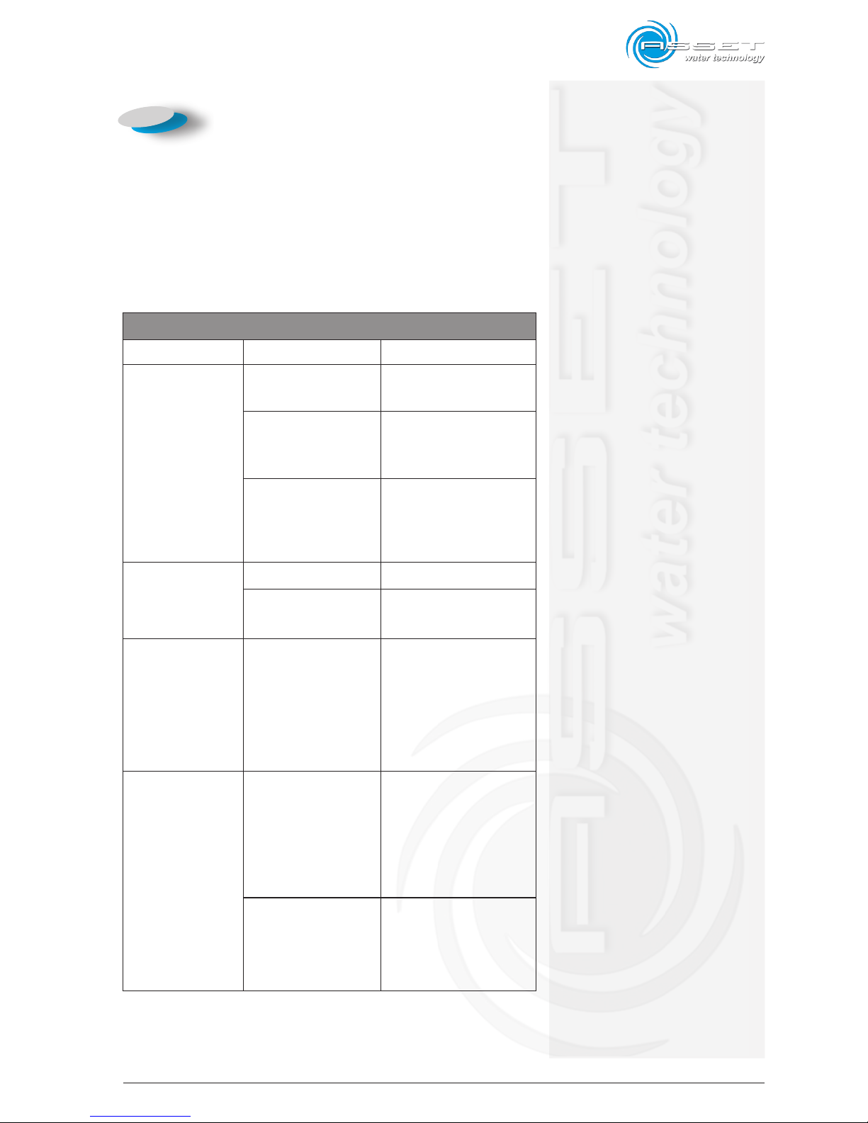
7.1 Solutions to problems
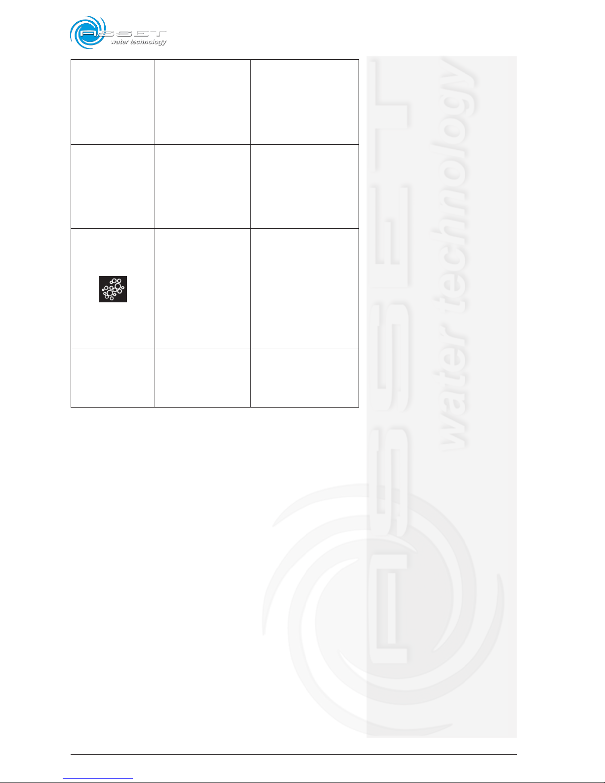
The following table shows some operating problems of the
dispenser that can be solved directly by the user without
involving the service centers.
PROBLEM CAUSE SOLUTION
The dispenser doesn’t
dispense water
Closed water tap Open the tap
Connection pipe to the
tap pressed;
or with throttling
Choose a path for the
pipe which prevents pressing
and throttlings
Lack of
power supply
Check the correct connection
between the power connec-
tion cable and/or the correct
operation of the electrical
system
The dispenser
dispenses little water
Obstructed filter Replace the filter
Low inlet water pressure
Contact the technical assi-
stance service
The dispenser cools
less
Insufficient or prevented
ventilation.
Check the correct position
of the dispenser
See paragraph Installation
Positioning. If the problem
persists, contact the technical
assistance service.
Water leakage
Filter installed in
a wrong way
Disconnect the power supply
plug, close the tap and
follow the instructions in the
Maintenance paragraph, filter
replacement
Internal damage
Disconnect the power supply
plug, close the tap, contact
the technical assistance
service
7. Trouble shooting
Page 56
7-2
ATLANTIS - Installation, Use and Maintenance - Man cod.-02 - Rev. 02/2011
The dispenser doesn’t
dispense sparkling
water when the
sparkling water
dispensing lever is
pulled.
Lack of CO
2
Replace or verify to have
opened the CO2 bottle
The dispenser
dispenses only gas
when the sparkling
water dispensing lever
is pulled
Blocked pump
Disconnect the power supply
plug for about 30 sec. Then,
connect it again. If the
problem persists, contact the
technical assistance service.
After pressing the
dispensing key
just a little sparkling
water is dispensed
Low pressure of the car-
bon dioxide.
Low pressure of the carbon
dioxide.
Increase pressure by rotating
gradually the handle of the
pressure regulator towards
the + sign If the problem
persists replace the CO
2
bottle; see paragraph
Maintenance – Start-up or
CO2 bottle replacement
The dispenser does not
dispense cold water
Frozen coil
Trouble to the ice bank
Carry out the ice bank defro-
sting procedure.
Adjust a higher temperature
on the thermostat
Page 57

7-3
ATLANTIS - Installation, Use and Maintenance - Man cod.-02 - Rev. 02/2011
Intentionally blank page
Page 58

7-4
ATLANTIS - Installation, Use and Maintenance - Man cod.-02 - Rev. 02/2011
Intentionally blank page
Page 59
8-1
ATLANTIS - Installation, Use and Maintenance - Man cod.-02 - Rev. 02/2011
The buyer and/or user can only carry out the interventions
specified in this manual.
The manufacturer declines any responsibility for any
intervention made by the buyer and/or user if not indicated
in this manual. Interventions not specified in the manual
and made by the buyer and/or the end-user during the
guarantee period, makes it expire immediately.
Interventions which result necessary and not specified
in the manual can be carried out only by the Technical
Assistance Centre or by the authorized Dealer.
8.1 Ordinary scheduled
maintenance cycles (HACCP)
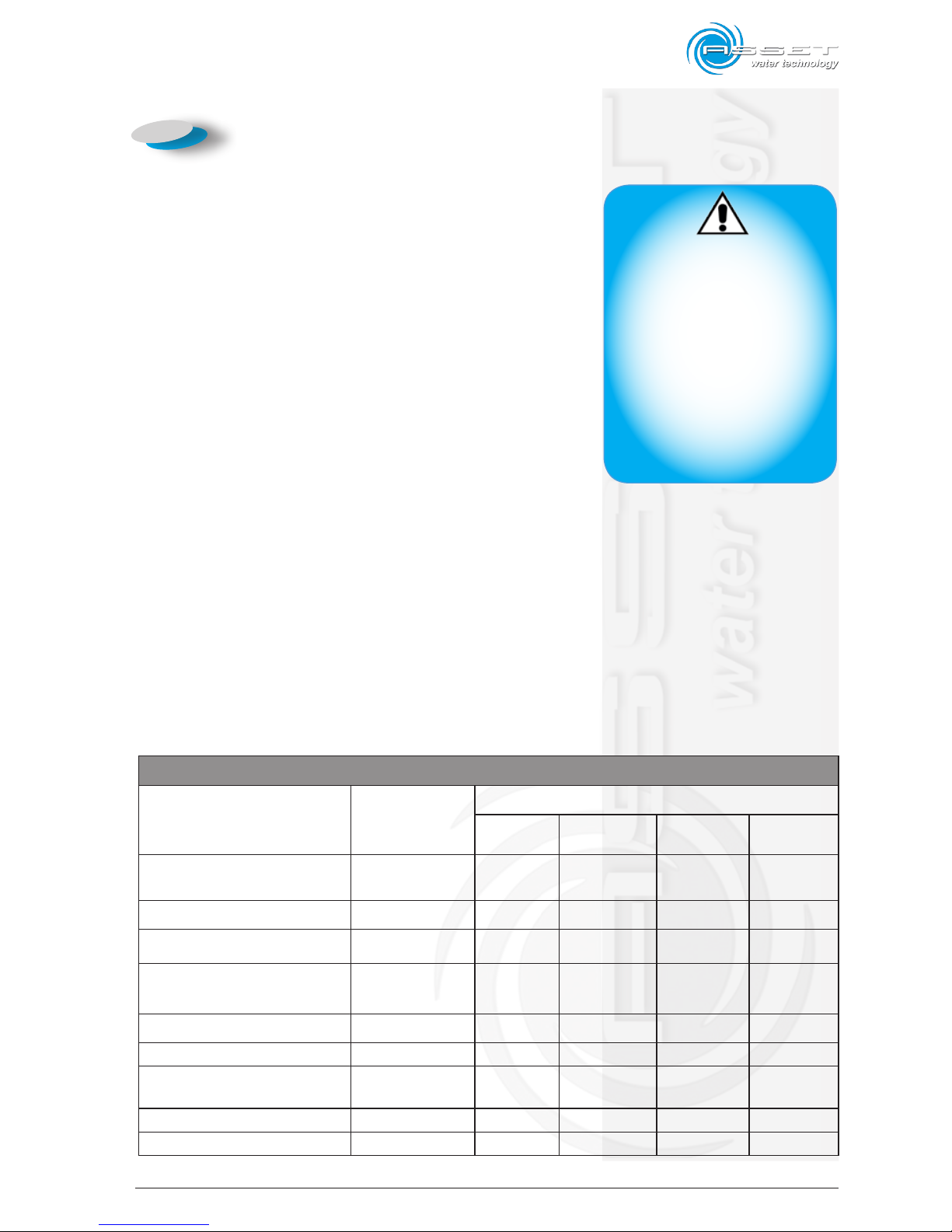
The following table states all the interventions of ordinary
maintenance to be carried out.
These periods of time refer to the normal condition of use
as established in the technical sheet. A more intensive
use can determine a reduction of the required intervals
of time.
ORDINARY SCHEDULED MAINTENANCE CYCLES (HACCP)
COMPONENT
TYPE OF
OPERATION
OPERATIONS FREQUENCY
Daily Weekly Half-yearly Yearly
External covering and front
panel
Cleaning X
Water Dispenser Sanitization X
Water filter Replacement X
UV lamp
(outer accessory)
Replacement X
Nozzle Sanitization X
Refrigerator condenser Cleaning X
Drip tray
Emptying and
cleaning
X
Ice bank water Replacement X
Ozone generator (if present) Replacement 24 months
8. Maintenance
WARNING
All the maintenance operations
must be carried out when the
machine is switched off and
power and water supplies disconnected. It is recommended to be
extremely carefully to remove
the power plug from the power
supply. Non-authorized interventions, on the machine, and/or
interventions made by unskilled
staff during the warranty period
makes it expire automatically.
Page 60
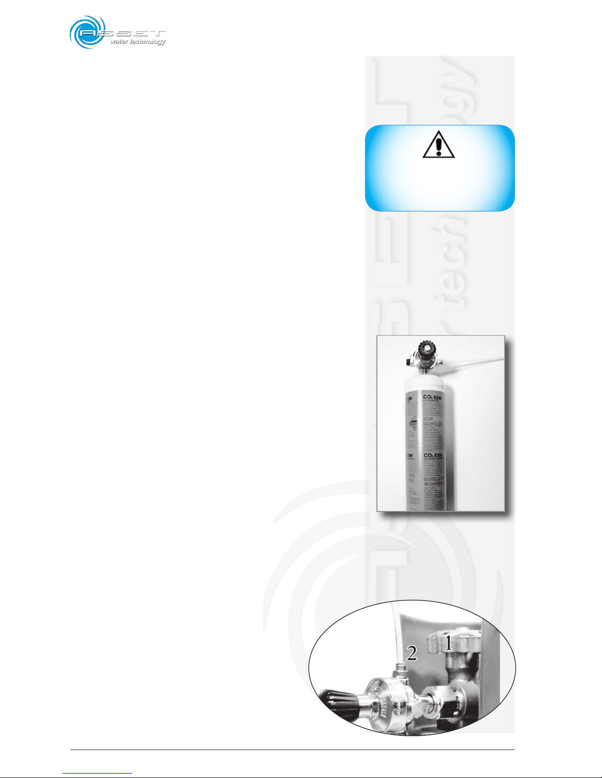
8-2
ATLANTIS - Installation, Use and Maintenance - Man cod.-02 - Rev. 02/2011
8.2 Replacement of the monouse or
rechargeable CO2 bottle
When gas is over, the device starts dispensing less
carbonated water and with a very reduced flow, so it is
necessary to replace the CO2 bottle.
It is possible to use monouse or rechargeable bottles;
the monouse can be utilized once; the rechargeable can
be refilled and used again and usually they have a bigger
content and autonomy.
8.2.1 Replacement of the monouse
bottle
Unhook the bottle (fig. 8.1) from its support binder and
with one hand clutch the pressure reducer and with the
other hand the bottle and unscrew it until it comes out
from the reducer.
Screw the new bottle on the pressure reducer by keeping it
vertical; near the end it is possible to hear a gas leakage
which will disappear with the complete blockage of the
bottle into the pressure reducer.
Position the bottle in its place and block it with the proper
chain belt.
If the gas leakage does not end, lock strongly the bottle
to the reducer or replace the sealing gasket. Do not expose
hands or any other part of the body to the gas because it
could cause freeze burns.
8.2.2 Replacement of the rechargeable
bottle
Close the upper hand wheel of the bottle
(fig.8.2 - n°1)by turning it clockwise until
it is completely locked.
Unscrew the hexagonal ring nut (n°2) which
couples the reducer to the bottle by using a
28mm adjustable spanner; check the status
of the gasket and if it is necessary, replace it.
CAUTION
Do not expose hands or any other
part of the body to the gas because it could cause freeze burns.
fig 8.1
fig 8.2
Page 61
8-3
ATLANTIS - Installation, Use and Maintenance - Man cod.-02 - Rev. 02/2011
Screw again the hexagonal ring nut of the reducer on the
new bottle and lock strongly with the adjustable spanner;
open the upper hand-wheel of the bottle.
Position the bottle in its place and block it with the
proper chain or belt.
8.3a Filter replacement (No Touch
Model)
ATTENTION: This operation must be carried out by skilled
technical staff or by technical service center or by the
authorized reseller only.
In relation to the type of filter, with a standard use of
the dispenser it is compulsory to change the water filter
cartridge at least once a year or every six months.
Once the filter is wet, even if the dispenser is not used,
it has to be replaced within a period of 12 months or in
accordance with the technical specifications of the filter
manufacturer.
At each filter change, it is a good rule to note down the
date of replacement by directly writing it permanently on
the new filter installed.
Proceed as follows:
- close the water interception tap;
- pull the room temperature water lever until the dispenser
doesn’t dispense water;
- release the new filter and insert the new one;
- open the interception tap of water and check the seal,
pull the room temperature water lever and dispense at
lest 10 litres of water.
However, dispense al least 3 – 4 litres of each type of
water also if the dispenser is not used for short time
(2-3 days).
After the filter replacement, it is compulsory to purge the
machine by dispensing at least 5 litres of water by pressing
the key (room temperature water dispensing).
Disregard of the purge operation could cause irreversible
damage to the machine.
It will be necessary to follow a sanitization cycle to prevent
possible bacteria contaminations. This operation must be
carried out by skilled technical staff or by technical service
center or by the authorized reseller only.
CAUTION
Before every filter replacement
it is suggested to carry out the
dispenser sanitization by using
the appropriate kit (optional and
not supplied with the dispenser);
this procedure must be carried
out exclusively by skilled technical staff, failure will make the
guarantee of the product expire.
IMPORTANT
Pay attention that the plastic
hose is not flattened or stretched.
Page 62
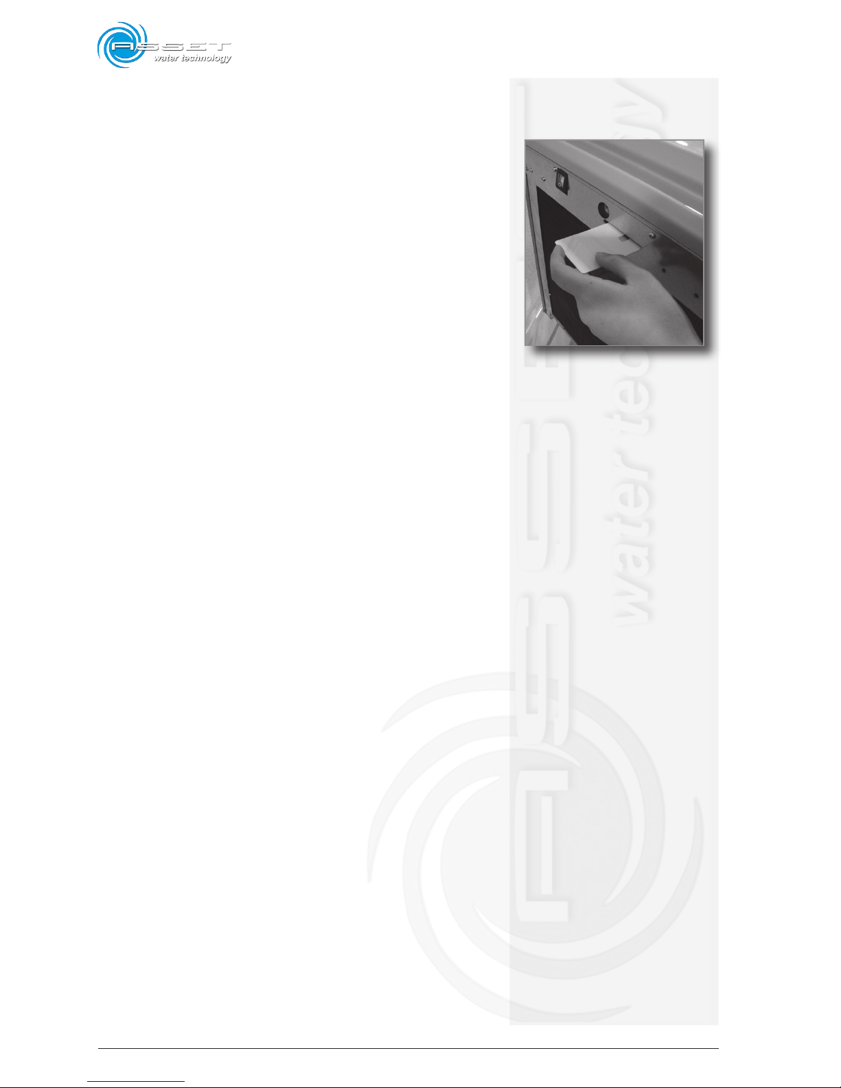
8-4
ATLANTIS - Installation, Use and Maintenance - Man cod.-02 - Rev. 02/2011
8.3b Filter replacement (Touch Model)
ATTENTION: This operation must be carried out by
skilled technical staff or by technical service center
or by the authorized reseller only.
ATLANTIS Touch Model is controlled by a microprocessor
which, through special sensors, signals any malfunction
and turns off the dispenser when dangerous conditions
arise, such as leaks. Inside the dispenser there is a
special monitoring system that, supported by the chip
card, controls the filter service life and advises the user
when it should be replaced.
In relation to the type of filter, with a standard use of
the dispenser it is compulsory to change the water filter
cartridge at least once a year or every six months.
Once the filter is wet, even if the dispenser is not used,
it has to be replaced within a period of 12 months or
in accordance with the technical specifications of the
filter manufacturer.
Each spare filter is equipped with an electronic smart card
that will be necessary to unblock the dispenser if one
of the previous conditions, that require the filter replacement, occurs.
The dispenser will also be blocked if the smart card is not
inserted or inserted in a wrong way.
At each filter change, it is a good rule to note down the
date of replacement by directly writing it permanently
on the new filter installed.
Proceed as follows:
1. insert the smart card, supplied with the new filter,in
the proper fissure (fig.8.3);
2. close the water interception tap;
3. press the room temperature water key and keep it
pressed until the dispenser doesn’t dispense water;
4. Place a cloth under the cartridge and subsequently
turn the coupling head of the cartridge of one-half
turn and remove it by pulling down;
5. fit again;
6. open the interception tap of water and check the seal,
press the room temperature water dispensing
key and dispense at least 10 litres of water;
7. make available a cloth, position it under the cartridge and subsequently turn the coupling head of the
fig 8.3
Page 63
8-5
ATLANTIS - Installation, Use and Maintenance - Man cod.-02 - Rev. 02/2011
cartridge of one-half turn and remove it by pulling
down (fig. 8.6);
8. insert again the new cartridge, pushing it up and screw
it again of one-haft turn;
9. open the interception tap of water and check the seal,
press the temperature water dispensing key and
dispense at least 10 litres of water;
Dispense al least 3-4 litres of each type of water also if
the dispenser is not used for short time (2-3 days).
Note: it is not necessary to insert the smart card for
the first start up of the dispenser.
It will be necessary to follow a sanitization cycle to prevent
possible bacteria contaminations. This operation must be
carried out by skilled technical staff or by technical
service center or by the authorized reseller only.
8.4 Replacement of the UV lamp
(outer accessory)
As indicated in the table of page 1, in devices equipped
with UV lamp (ultraviolet rays) it is necessary to replace
the bulb lamp every 12 months (maximum).
This operation has to be carried out only by skilled
staff and, for this reason, it is necessary to contact the
technician or the authorized reseller.
Note: UV radiations can cause damages to the eyes and
skin: never expose to direct radiation.
8.5 Cleaning
To keep the dispenser in good conditions even after a
long use, it will be necessary to clean periodically its
external surfaces.
To clean it, turn off the machine, disconnect from the
power supply and close the water tap.
For cleaning do not use used or dirty cloths since the
dispensing point that was sanitized before the dispatch
could be inexorably contaminated. For example, for cleaning
WARNING
Never disconnect the power cable
but – if the dispenser is not used for
long time – only close the water tap.
WARNING
UV radiations can cause damages to the eyes and skin:
never expose to direct radiation
Page 64

8-6
ATLANTIS - Installation, Use and Maintenance - Man cod.-02 - Rev. 02/2011
use a new piece of blotting-paper slightly dampened
with not aggressive detergent and disinfectant products
diluted in water.
Do not touch the dispensing points with dirty hands.
Do not use solvents or alcohol-based products. The
ventilation slits of the dispenser, on the right side, must
be cleaned by using a dry brush.
8.6 Water dispenser sanitization
Every 6 ÷ 12 months of use of the dispenser, it will be
necessary to follow a sanitization cycle to prevent possible
bacteria contaminations.
This operation must be carried out by skilled technical
staff or by technical service center or by the authorized
reseller only.
In case of a long inactive period in which the dispenser
is not used, it is compulsory to carry out a sanitization
cycle; sanitize the dispenser after each filter replacement
or after a period in which the dispenser is not used for
one or more weeks. Every week of use, as stated in the
previous table, sanitize the dispensing nozzle.
Unscrew the nozzle and dip it in a sanitizing liquid for
food use, for about 10-15 min. Then, rinse the dispensing
nozzle copiously, with water and screw it again in its seat.
8.6.1 Dispenser sanitization procedure
(with Everpure filter)
ATTENTION: This operation must be carried out by
skilled technical staff or by technical service center
or by the authorized reseller only.
By using the appropriate sanitization kit, proceed as
follows:
1. Close the tap that supplies water to the dispenser.
2. Pull the room temperature water lever (central tap)
until the dispenser doesn’t dispense water.
3. Release the water filter to be replaced from the sup-
port, rotating it of one half-turn.
4. Insert a dose (1 glass) of sanitizing liquid (laundry
bleach, for ex. AMUCHINA) in the container of the
Page 65

8-7
ATLANTIS - Installation, Use and Maintenance - Man cod.-02 - Rev. 02/2011
sanitization kit (optional - not included) using the
dosing cap and then fill the water container to the
rim (use preferably warm water).
5. Insert the container in place of the filter, pushing it
up and screwing it half-turn making sure that it is
correctly hooked in its seat.
6. Open the tap that supplies water to the dispenser.
7. Pull the room temperature water lever (central lever)
and dispense 2 glasses of water.
8. Pull the cold water lever (right lever) and dispense 3
glasses of water.
9. Pull the sparkling water lever (left lever) and dispense
one litre of water.
10. Wait 30 minutes and repeat the operations of points
7 - 8- 9 ; wait other 10 minutes and dispense
at least
4 litres of water for each tap in order to eliminate
any residue of sanitizing liquid.
11. If a chlorine flavour is perceived after the sanitization, dispense more water in order to remove it.
12. Close the tap that supplies water to the dispenser.
13. Pull the room temperature water lever (central lever)
until the dispenser doesn’t dispense water.
14. Unscrew the container of the sanitization kit of one
half-turn, pulling it down until it comes out.
15. Insert the filter that was previously removed or the
new filter if it was to be replaced, pushing it up and
screwing it half-turn making sure that it is correctly
hooked in its seat (see paragraph 8.3 filter replacement).
16. Open the tap that supplies water to the dispenser.
17. Note down the date of the sanitization operation and
the litres displayed on the litrecounter (if present).
8.6.2 Taps sanitization
It is necessary to sanitize the Taps frequently and to remove any formation of Mineral salt or limescale. Proceed
as follows:
- place a container (for ex. a glass) containing a scale-
dissolver solution for domestic use available in the
market;
- immerse the Taps in the container with the substance
and let it work for the time suggested;
- rinse with clean water.
Page 66

8-8
ATLANTIS - Installation, Use and Maintenance - Man cod.-02 - Rev. 02/2011
8.7 Technical assistance
In order to optimize the Support and Assistance service,
ASSET makes use of a network of Resellers and Authorized
Distributors that supports Clients for any possible request
of Service.
Therefore the Final User must only contact the Reseller
where he purchased the machine for any request of
Assistance or Technical Support.
ASSET Resellers have complete access to our Technical
Support resources and a full knowledge of the possible
problems that could stand out.
They are also the sole able to send a RMA request to our
Company since ASSET does not sell directly to Final Users.
Page 67
9-1
ATLANTIS - Installation, Use and Maintenance - MAN cod.-02 - Rev. 02/2011
9.1 Dispenser dismantling
The dispenser must be dismantled after disassembling the
different parts that make it up.
Request the Retailer for specific information regarding
the dismantling operations.
Once disassembled the different parts, subdivide the different components separating metal from plastic, copper,
etc. according with the type of separate waste disposal in
force in the Country where the dispenser is dismantled.
In case it is necessary to store the different components
waiting to be accepted in the dump, pay attention to preserve them in a safe place sheltered against atmospheric
agents, in order to prevent contamination of ground and
water.
9.2 Electronic components
disposal
The community directive 2002/96/EC, adopted in Italy
with legislative decree n. 151 of the 25th of July 2005,
imposes to manufacturers and users of electric and electronic
equipment a series of obligations related to the collection,
treatment, reuse and disposal of this kind of waste.
Pay attention to the waste disposal regulations in
force.
Keep in mind that unauthorized disposal of this kind of
waste involves application of financial penalties provided
by regulations in force.
9. Dismantling
CAUTION
Instructions related to this
chapter are to be intended
just as an indication. Refer to
the regulations in force in the
Country where the device is used.
Page 68

9-2
ATLANTIS - Installation, Use and Maintenance - MAN cod.-02 - Rev. 02/2011
Intentionally blank page
Page 69

10-1
ATLANTIS - Installation, Use and Maintenance - Man cod.-02 - Rev. 02/2011
10.1 Identification and ordering
modes
Diagrams and drawings to identify the different parts
are available in the technical file of the machine in the
Manufacturer’s archives, therefore any request of spare
parts must be sent to Manufacturer.
For trading parts, if the Manufacturer considers it useful,
it is possible to supply technical manuals or the original
documentation of the supplier.
If these are not supplied, they are however included in the
Technical File of the machine in the Manufacturer’s archives,
as provided by the Ministerial Decree 2006/42/EC.
If necessary contact the Technical Service to identify
the needed part.
If the needed parts are not included in any position, or
it is impossible to identify them, contact the Technical
Service indicating the type of machine, the serial number
and the year of manufacture.
These data are included in the identification label positioned on the machine.
10. Spare parts
Page 70

10-2
ATLANTIS - Installation, Use and Maintenance - Man cod.-02 - Rev. 02/2011
Intentionally blank page
Page 71
Start up
This device was started up on:
by the qualified Company:
Name of the Qualified Installer:
Signature:
Location address:
Device owner:
Maintenance certificate
Hereby we confirm that the device was checked after the maintenance and
repair service and is perfectly operating.
Service carried out on:
Date: Qualified Company:
Signature: Name of the Qualified Installer:
Hereby we confirm that the device was checked after the maintenance and
repair service and is perfectly operating.
Service carried out on:
Date: Qualified Company:
Signature: Name of the Qualified Installer:
Hereby we confirm that the device was checked after the maintenance and
repair service and is perfectly operating.
Service carried out on:
Date: Qualified Company:
Signature: Name of the Qualified Installer:
Page 72

ASSET S.r.l.
Loc. Isola del Pero, 16 - 17041 - ALTARE (SV) - ITALY - Tel: +39 019 58 48 30
Fax: +39 019 51 42 186 - e-mail: [email protected] - www.assetitalia.it
ASSET declines all liability for any damage to people or property caused by incorrect use of this product.
Subject to change without prior notice.
 Loading...