

Page 1
ASSEMBLAD s.a.s. - Costruzioni Elettroniche
50013 - Campi Bisenzio - Firenze - Italy
SAMPLING SMOKE METER
Model OPA-189
USER MANUAL
February 1997, Rev. V1.00
ASSEMBLAD - Engineering Department - Automotive Division
File: c:\winword\189\M189gb10.doc
Page 2

OPA 189 User Manual
2
TABLE OF CONTENTS
1 INTRODUCTION page 4
1.1 Fittings supplied page 4
1.2 Smoke Meter - Front page 4
1.3 Smoke Meter - Back page 5
2 TECHNICAL FEATURES page 6
2.1 Photodetector - Technical Features page 6
2.2 Measuring Chamber - Technical Features page 6
2.3 Method for Taking Measurements page 6
2.4 Standards page 6
2.5 Electronic Structural Features page 7
2.6 Settings and Controls page 7
2.7 Power Supply page 7
2.8 Supplementary Functions page 7
2.9 Other Features page 8
3 KEYPAD page 9
4 INFRARED REMOTE CONTROL page 12
5 STARTING THE SMOKE METER page 13
5.1 Power Supply Connections page 13
5.2 Start-Up page 13
5.3 Preparation for Measurements page 14
5.4 Messages at Start-up page 15
6 SMOKE MEASUREMENTS page 16
6.1 Keypad Settings page 16
6.2 Continuous Smoke Measurement page 16
6.3 Smoke Measurement as per CUNA Standards (Italy) page 17
6.4 Smoke Measurement according to directive ECC 72/306 page 18
7 RESETTING WITH THE FILTER page 19
8 REPLACING THE HALOGEN LAMP page 20
9 CLEANING THE MEASURING CHAMBER page 21
10 TEMPERATURE READINGS page 22
Page 3

OPA 189 User Manual
3
11 PRESSURE/DEPRESSION MEASUREMENTS page 22
12 POWER SUPPLY VOLTAGE page 22
13 PRINTER page 23
14 REPLACING FUSES page 24
15 ERRORS page 25
15.1 Function Errors Reported to the Operator page 25
15.2 Function Errors That Cannot Be Immediately resolved page 26
16 SMOKE-INTERCEPT SOLENOID VALVE
MAINTENANCE page 27
APPENDIX page 28
WARRANTY page 29
Page 4
OPA 189 User Manual
4
1 INTRODUCTION
1.1 FITTINGS SUPPLIED
N. 1 Rubber sampling hose
N. 3 Exhaust pipe connectors
N. 1 Ballast
N. 1 220 VAC mains lead
N. 1 Battey mains lead
N. 1 Calibration filter
N. 1 Infrared remote control device (without battery)
N. 1 User manual
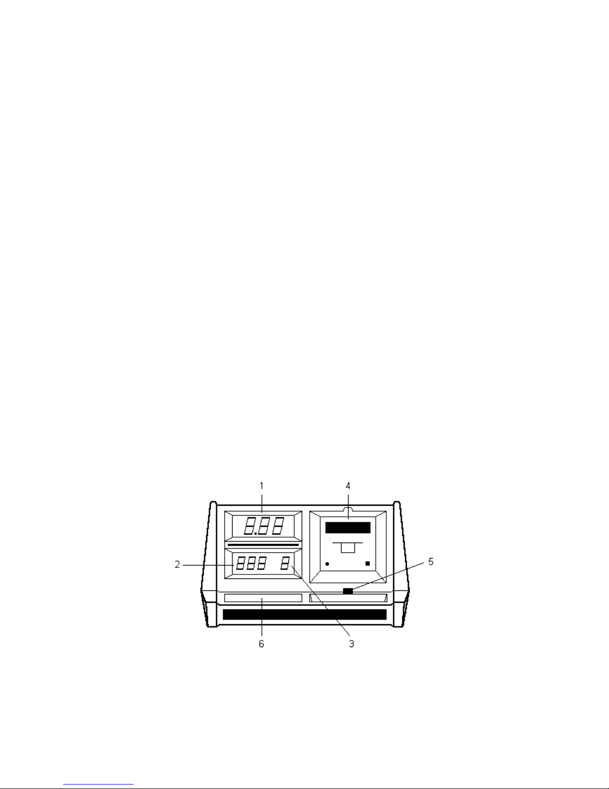
1.2 SMOKE METER - FRONT
1) Smoke value display
This display shows the SMOKE values of the vehicle exhaust gases expressed as
percentage from 00.0 to 99.9% and in K from 0.00 to 9.99 (m-1).
2) Temperature display
This display show the temperature of the gas entering the measuring.
3) Display of test number being performed/that can be performed.
4) 24 column pin printer
5) Infrared remote control receiver
6) Control keypad and function lights
Keys: ON/OFF, %/K, MODE, COUNT ADV, ZERO, PRINT, PAPER ADV.
LEDS: ON, +15%, -15%, %, K, CONT, ITALY, CEE.
Figure 1
Page 5

OPA 189 User Manual
5
Page 6
OPA 189 User Manual
6
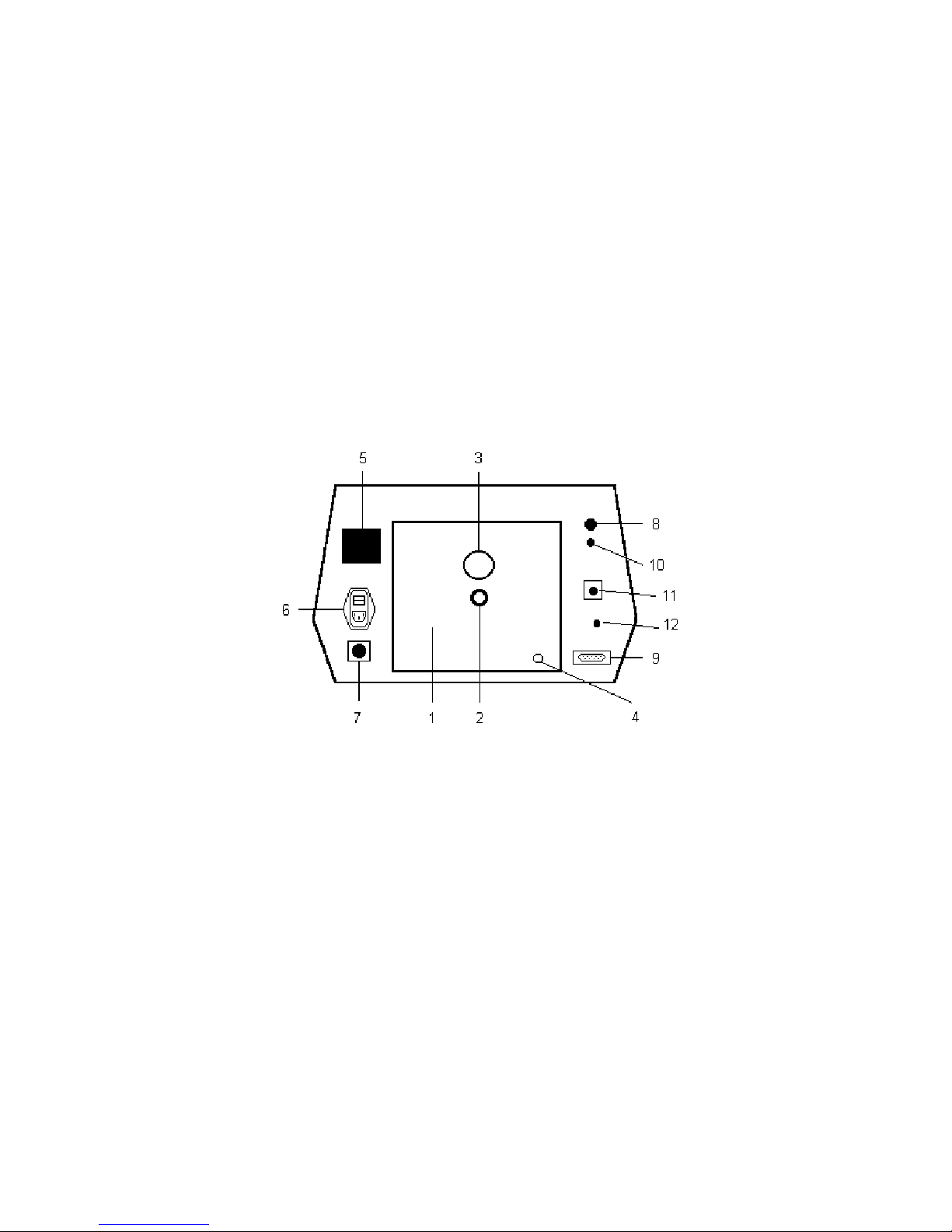
1.3 SMOKE METER - BACK
1) Measuring Chamber
2) Fitting for exhaust gas input
3) Exhaust gas vent
4) Fitting for releasing condensate formed in the measuring chamber
5) Metal label-plate
6) Switch filter complete with: prestart filter, fuses, mains outlet
7) Connector for vehicle-battery power supply (13.8 VDC)
8) Not used
9) Not used
10) Not used
11) Not used
12) Calibration Filter
Figure 2
Page 7

OPA 189 User Manual
7
2 TECHNICAL FEATURES
2.1 Photodetector - Technical Features
"Reflection" type transceiver:
Transmitter - 6V 10W halogen lamp
Color temperature - 3000°K
Lamp filament voltage - Microprocessor controlled
Average lamp life - 2000 hours
Receiver - BPW21 photodiode
Response corrector filter - L.I.S.S. passband
Periodic settings - Neutral wire supplied
2.2 Measuring Chamber - Technical Features
Chamber ventilation - Controlled
Measuring cell length - 198 mm
Measuring cell, inside diameter - 36 mm
Actual length of an exhaust gas
specimen - 400 mm
Exhaust gas input - Balanced
Clean air input - Balanced
Exhaust gas intercept - 1/2 inch solenoid value
Clean air intercept - 1/8 inch solenoid valve
Gas discharge - By ventilation
Pressure/depression sensor - Differential, solid state
Temperature probe - Integrated circuit
Measuring chamber - Interchangeable
Chamber mechanics - Inspectable
Condensate drainage - At the base of the chamber
2.3 Method for Taking Measurements
Continuous measurement - For motors being bench-tested
Italy measurements - 5 accelerations as per Italian Law n. 615 dated
13/07/66
EEC measurements - 6 to 8 accelerations in accordance to directive ECC
72/306
2.4 Standards
Meets CUNA NC-005/11 standards
Page 8

OPA 189 User Manual
8
2.5 Electronic Structural Features
Setting - Automatic when switched on
Microprocessors - 2 (Motorola MC68705R5 and MC68705U5)
Measurement processing - Microprocessor controlled (measure-
ment card)
Measurement display - Microprocessor controlled (display card)
Printer - Impact, 24 columns
Smoke display - 3, 7-segment high intensity LEDS 20 mm high, red
Temp display - 3, 7-segment high intensity LEDS 20 mm high,
green
Test N° Display - 1, 7-segment high intensity LED 14 mm high, green
Measurements displayed - Smoke: from 00.00 to 99.9%
Smoke K (m-1) from 0.00 to 9.99
Gas temp: from 0 to 150°C
Solenoid valves - Stabilized power supply
Chamber ventilation - Controlled delivery
Start-up and self-test time - 1 min, normal
Time to reach optimum operating
rates - 5 min, normal (at 25°C)
Messages - On display and printed
Operating temperature - +0° to +45°C
Humidity range - 45%-90%
Clearing measurement device - Automatic, press ZERO key
2.6 Settings and Controls
Console keypad - Synoptic touch type
Function keys - Seven
Measuring lights - Eight LEDs on keypad
Remote control - Infrared
Remote control signal receiver - On front of console
2.7 Power Supply
From mains - Single phase 50 Hz (±2%)
220V (±10%)
From battery - 13.8 VDC (-15%+10%C)
Absorbed power - from mains, 50VA, normal
from battery, 50 W, normal
2.8 Supplementary Functions
Gas temperature probe - built-in
Page 9

OPA 189 User Manual
9
2.9 Other Features
Approximate dimensions - 480 x 300 x 630 mm
Weight - 25 kg, approx.
Exhaust pipe connectors - To be connected to the hose connected to the
instrument; 3 different sizes, inside diameters of 10,
17 and 27 mm
Ballast - 2 kg approx; to connect to the hose
connected to the instrument to take
stable gas specimens
Page 10
OPA 189 User Manual
10
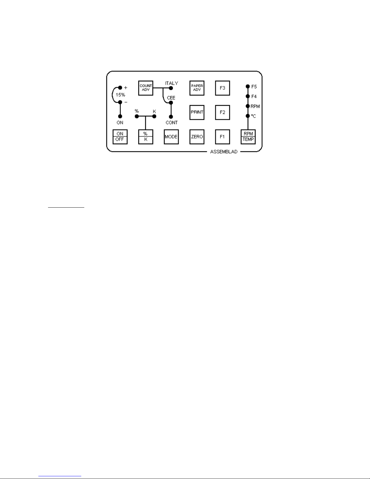
3 KEYPAD
Figure 3
Description:
ON/OFF This key switches the smoke meter on and off. It only
functions if the ON led is lit. The key is timed at about 0.5
seconds to prevent inadvertent switching. Each time the
instrument is turned on, the smoke meter automatically goes
through a self-test and setting procedure (the messages
concerning instrument status are either printed or shown on the
display).
%/K Use this key to display smoke values, that is in terms of
percentage on a 00.0% to 99.9% scale, or with the K (m-1)
factor. The form you select is confirmed by the % and K LEDs.
The machine is automatically in the % mode when it is switched
on.
MODE Use this key to set the desired measuring mode. You can select
from: CONT (continuous measurement of smoke values), ITALY
(measurement of mean smoke value according to CUNA NCOO5/11 standards - law n.615 dated 13.07.1966) or CEE
(measurment of mean smoke value according to the ECC
directive n. 72/306).Your selection will be shown on the
respective LED CONT, ITALY, CEE. When measuring in the
ITALY or CEE modes, the MODE key is inhibited by the
program; it will only be released if you give a clear or PRINT
command when measuring is completed. The machine is
automatically in the CONT mode when it is switched on.
Page 11

OPA 189 User Manual
11
COUNT ADV Use this key to increment measurements in the ITALY or CEE
modes. The measuring increment is timed for 3 seconds to
prevent program skips if you do not press the key properly. If you
are measuring in the ITALY mode, the increment will stop at the
fifth test; in the CEE mode increments are possible up to the
tenth test.
ZERO Use this key to clear the measurement in progress and recover
the initial drift after the pre-heating phase. Press this key each
time you start a new measuring procedure During this phase the
smoke meter will clean out gases from the chamber and recheck
the settings.
PRINT Press this key to if you want a print-out of the results of a
measurement. If the machine is in the CONT mode you can print
at any time. If it is in the ITALY or CEE mode it will only print
after having completed the number of measurements required
for the test. You can make as many reprints of a measurement
as you want until you press the ZERO key.
PAPER ADV Use this key to advance the printer paper. If you keep the key
depressed as you press the ON/OFF key (switching on the
smoke meter) you will obtain a function TEST of the printer.
RPM/TEMP Not used
F1 Not used
F2 Not used
F3 Not used
Page 12

OPA 189 User Manual
12
The LEDS:
ON When this LED is lit, it means that the smoke meter is already
connected to the vehicle's battery or the 220VAC mains power
supply. If the device is connected to the mains, the switch on the
back has to be set to ON. When this LED is lit, it means that the
smoke meter is ready to be switched on.
+15% When this LED is lit it means that the power supply to the smoke
meter is 15% above the rated value. This can damage the
smoke meter or impact the results of the measurements if it is
not corrected.
-15% When this LED is lit it means that the power supply to the smoke
meter is 15% below the rated value. This can alter results of the
measurements, or yield a printout with a pre-depression error
signal if it is not corrected.
% When this LED is lit, it means that the smoke measurements on
the display are expressed in percentage terms.
K When this LED is lit, it means that the smoke measurements on
the display are expressed according to the K(m-1) factor.
CONT When this LED is lit, it means that the CONTINUOUS mode has
been selected for measuring smoke values.
ITALY When this LED is lit, it means that the smoke values will be
measured in accordance with CUNA 005/11 standards as per
Italian law n.615 dated 13.07.66.
CEE When this LED is lit, it means that smoke values will be
measured in accordance with the directive ECC 72/306.
C° Not used
RPM Not used
F4 Not used
F5 Not used
Page 13

OPA 189 User Manual
13
4 INFRARED REMOTE CONTROL
This device consists of 4 keys that you need to start the measuring functions, even while
driving the vehicle.
KEYS
:
MODE Use this key to select the measurement mode: CONTINUOUS
(CONT) according to CUNA standards, as per Italian Law N.615
dated 13.07.66 (ITALY), and according to the directive 72/306
(CEE). Each time you press the MODE key, the machine will
shift over to the next method. The position is shown on the
LEDS.
ADV Use this key to increment test number when working in the
ITALY or CEE modes.
ZERO Use this key to clear the smoke meter
PRINT Use this key to print the results of measurements, you can print
multiple copies.
The remote control device is powered by a 9VDC battery (use an alkaline
type battery); the battery housing is on the back of the devices.
IMPORTANT: The infrared receiver on the console (see Fig.1, item 5) must never receive
strong, direct light, such as lamps with strong infrared rays, or sunlight; this can "blind" the
device and the remote control will not work any more. If necessary turn the machine
around so that any direct light falls on the back part and not on the front.
Page 14

OPA 189 User Manual
14
5 STARTING THE SMOKE METER
5.1 Power Supply Connections
Select the power supply for the smoke meter. Usually 220VAC mains power is used. If it is
not available, connect the smoke meter to the battery of the vehicle being tested, or to a
fully-charged shop battery.
MAINS POWER SUPPLY
Connect the smoke meter to a 220VAC outlet using the cable supplied with the device; set
the switch on the back to ON. The ON LED on the keypad with will light up (if you set the
switch to OFF, the LED will go out very slowly).
BATTERY POWER SUPPLY
Connect the smoke meter to a 12V battery using the cable that is supplied with the device.
Make sure that the cable is properly inserted and screwed into the round connector on the
back of the device before connecting the battery. Check polarity as you connect to the
battery: Red clip = Positive, Black clip = Negative. The smoke meter is protected against
inversions, but be careful when making these connections. As soon as the battery cable is
connected the ON LED will light up, irrespectively of the back switch position.
5.2 Start-Up
When the ON LED is lit, press the ON/OFF key. The smoke meter will now switch on, and
go through a series of selftest and setting procedures automatically.The self-test series
consists of several steps; you can see the following ones:
a) All the displays will read 8
All the LEDs are lit.
b) The displays will all read zero, except for N°TEST that will read 1.
The ON, %, CONT, C° LEDS will remain lit.
The printer will start sending a partial message.
c) The N° TEST display will read 2.
The two other displays will blink on zero.
The printer will stop.
d) All the displays will read zero.
The printer will complete its message.
e) The temperature display will show the actual temperature in the measuring chamber.
The smoke display will show a value around zero, oscillating by a few units. (The
initial oscillation is due to the intrinsic stabilization of the filament, and will continue
for a few minutes after the device is turned on).
Page 15

OPA 189 User Manual
15
Select the unit of measure K (%/K key) if you want to see the smoke value display in
terms of the K factor rather than a percentage (the % position is selected automatically
when the machine is turned on).
Select the measurement mode using the MODE key to select ITALY or CEE (CONT is
selected automatically when the machine is turned on).
Press the ZERO key to clear the smoke values from the display The display will blink
during the automatic clearing phase. Clearing may not work the first time, therefore,
repeat the procedure until you get zero (the value on the display should not be higher than
00.5%).
NOTE: If any problems occur during this initialization procedure such as inadequate
settings, defects inside the machine, etc., the smoke meter will go into the alarm mode
and will send messages via the printer specifying the type of problem and, whenever,
possible how to solve it. If the problem is more serious, all the displays will blink and LEDS
will blink at the same time (see the section on errors).
5.3 Preparation for Measurements
Bring the engine to its normal operating temperature.
Connect the vehicle exhaust pipe to the smoke meter using the hose that comes with the
instrument. Fit the hose into the 19mm fitting on the back of the measuring chamber.
Connect the other end of the hose onto the vehicle's exhaust pipe. To take gases from
inside the exhaust pipe, use one of the three metal fittings supplied with the instrument
(use the small probe with the conical fitting for pipes with diameters up to 35 mm; the
medium size probe for pipes with diameters of 35 to 80 mm, and the biggest one for
exhaust pipes with diameters exceeding 80 mm).
Use the ballast to prevent the engine's vibrations from shaking the hose loose during
testing.
Page 16

OPA 189 User Manual
16
5.4 Messages at Start-Up
When you turn on the instrument the printer will issue a message like this:
ASSEMBLAD
COSTRUZIONI ELETTRONICHE
FIRENZE - ITALY
OPACIMETRO MOD. 189
OMOL. PROT. 601/4103/8-L
AUTOTEST AUTOTARATURA
IN PROGRESSIONE
which means that self-testing and self-setting are in progress.
After this first message, the machine will complete all the internal tests as required by the
program. Then, if everything is in proper order, the printer will continue with:
AUTOTEST = OK
AUTOTARATURA = OK
which means
Self-test = OK
Self-setting = OK
If any errors or other malfunctions are found, the printer will send a message specifying
the problem and, if possible, how to solve it.
Page 17

OPA 189 User Manual
17
6 SMOKE MEASUREMENTS
6.1 Keypad Settings
CONTINUOUS MODE
When the smoke meter is switched on it is automatically ready to work in this mode, and
to give readings on the percentage scale. To be able to take measurements, the CONT
LED must be on (otherwise, press the MODE key).
You can print the values shown on the display at any time.
ITALY MODE (CUNA Standards - Law 615 dated 13.07.66)
After the automatic self-test/self-setting sequence, you must press the MODE key until the
ITALY LED lights up. The program will now be ready to measure smoke levels according
to the requirementsof CUNA NC 005/11 standards - Law 615 dated 13.07.66.
CEE MODE ( In accordance to directive ECC 72/306 )
After the automatic self-test/self-setting sequence you must press the MODE key until the
CEE LED lights up. The program will now be ready to measure smoke levels according to
the requirements of the ECC directive 72/306.
6.2 Continuous Smoke Measurement
Measurements are continuous in the sense that the smoke values of the gases are shown
continously: the value on the display is the smoke value that is being "read" at that instant.
This type of measurement is particularly useful in bench tests, since it shows the smoke
values as they rise and fall.
The print-outs of these results do not have any legal value since the reading is an
absolute result and not the results of an average of readings taken according to specific
standards.
Page 18

OPA 189 User Manual
18
6.3 Smoke Measurement as per CUNA Standards (Italy)
This method makes it possible to work in accordance with the requirements of Italian Law
n.615 dated 13 July 1966. To take measurements follow the procedure described below:
a) Before starting the test disconnect any devices on the vehicle that can reduce the
pollutants in the exhaust gases by mixing them with air.
b) Connect the smoke meter's sampling hose to the vehicle exhaust pipe.
c) Before taking the measurements, accelerate fully three times and as quickly as
possible, and bring the engine to maximum power each time, if there is a governor,
then to the maximum allowed. Take the measurements during further complete
accelerations immediately following the first three.
d) Press the MODE key and select ITALY.
e) Press the ZERO key and wait for the instrument to clear.
f) Press the COUNT ADV key (the N° TEST display will read 1). Accelerate all the way,
until you reach maximum power and then release the accelerator. The display will
show the maximum smoke or pollution value reached in that phase.
g) Press the COUNT ADV key (the N° TEST display will read 2). Accelerate as
described in (f), above.
h) Repeat steps (f) and (g) for a total of 5 measurements.
i) After the fifth acceleration (N° TEST 5) press the PRINT key. The printer will give
the mean caculated on the basis of the 3 closest values. The display will show that
mean value.
NOTE: Up to and including the fourth test you can interrupt the measurements and clear
the smoke meter. After you have run the fifth test you cannot clear the machine, you must
press the PRINT key (the reason for this is to prevent you from losing all the
measurements you have taken if you accidentally press the ZERO key).
The printer will give the 5 (five) data on smoke levels obtained during the 5
measurements, expressed in the selected unit of measure (% or K), but the mean value
will be expressed in (%).
Page 19

OPA 189 User Manual
19
6.4 Smoke Measurement according to directive ECC 72/306
This method makes it possible to work in accordance with the requirements of the
directive 72/306 . To take measurements follow the procedure described below:
a) Before starting the test disconnect any devices on the vehicle that can reduce the
pollutants in the exhaust gases by mixing them with air.
b) Connect the smoke meter's sampling hose to the vehicle exhaust pipe.
c) Before taking the measurements, accelerate fully three times and as quickly as
possible, and bring the engine to maximum power each time, if there is a governor,
then to the maximum allowed. Take the measurements during further complete
accelerations immediately following the first three.
d) Press the MODE key and select CEE.
e) Press the ZERO key and wait for the instrument to clear.
f) Press the COUNT ADV key (the N° TEST display will read 1). When the engine is at
the minimum number of RPMs, accelerate quickly but gently until the injection
delivery is at maximum. Maintain this position until the engine reaches its maximum
number of RPMs. Then release the accelerator until the engine returns to the
minimum number of RPMs.
g) Press the COUNT ADV key (the N° TEST display will read 2). Accelerate as
described in (f), above.
h) Repeat steps (f) and (g) press COUNT ADV until the 6 minimum test (max. 8).
i) After you have reached the stabilized average press the PRINT key. The printer will
give the mean calculated on the basis of the selected standard. The display will show
that mean value expressed in K(m-1).
NOTE:
The printer will give the data on smoke levels obtained during the measurements
performed, expressed in the selected unit of measure (% or K), and finally the mean
smoke value calculated as described in i), above.
The symbol "#" will appear next each of the 4 measurements used to calculate the
average.
The maximum number of tests is 8.
Page 20
OPA 189 User Manual
20
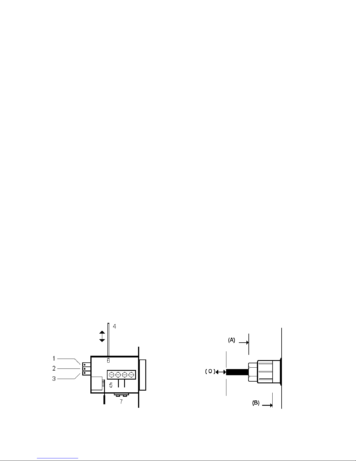
7 RESETTING WITH THE FILTER
A filter is supplied with the smoke meter. The filter's absorption factor is specified so you
can use it to check the accuracy of the smoke meter's measurements and/or settings.
To check or set the values shown on the instrument, proceed as follows:
1 Switch on the smoke meter.
2 The following LEDS should light up: ON, %, CONT, °C.
3 Open the top hinged cover on the smoke meter.
4 Let the initial drift stabilize (about 15 minutes).
5 Press the ZERO key to clear the measurement.
6 Place the filter (4) in the rear slot on the photoelectric cell unit (6), or insert (O) as far
as the position (B)
7 Watch the display; it should show a percentage absorption value equal to that shown
on the filter ±1.0%.
8 If the difference exceeds ±1.0% you have to reset the device, use the potentiometer
(2) to do this.
9 Once you have reached the indicated value, remove the filter [or to free (O)].
10 Press the ZERO key and wait for the device to clear.
11 Reinsert the filter and make sure that the nominal value on the filter is exactly the
same as the value on the display (±0.5%). If necessary, reset repeating from step
(8).
IMPORTANT: NEVER CLEAR THE SMOKE METER WITH THE FILTER INSERTED.
Page 21

OPA 189 User Manual
21
Figure 4
Page 22

OPA 189 User Manual
22
8 REPLACING THE HALOGEN LAMP
To replace the lamp on the photoelectric cell, proceed as follows:
1 Switch off the smoke meter and disconnect it from all power supplies.
2 Open the hinged door on top of the smoke meter.
3 Use the 3 mm Allen key supplied with the device to loosen the two screws (7) that
support the lampholder's fastening plate.
4 Replace the lamp with another 6V 10W halogen lamp; we recommend OSRAM
HALO STAR N.64410.
5 Insert the lamp into the shoe as centrally as possible.
6 Clean the lamp with denatured alcohol before you put it into the photoelectric cell
(dirt or grease will drastically reduce the service life of all halogen lamps).
7 Put the fastening plate back onto the photoelectric cell; make sure that the
lampholder is properly guided and fastened into position by the two pointed screws
(their length is preset in the factory and must not be adjusted).
8 Replace the two Allen screws and tighten securely.
9 Switch on the smoke meter.
10 Carry out the procedure described in the previous section "7. RESETTING WITH
THE FILTER".
Figure 5
Page 23
OPA 189 User Manual
23
9 CLEANING THE MEASURING CHAMBER
To clean the measuring chamber, proceed as follows:
1 Switch off the smoke meter and disconnect it from all power supplies.
2 Open the hinged cover on top of the smoke meter.
3 Remove the cover from the measuring chamber.
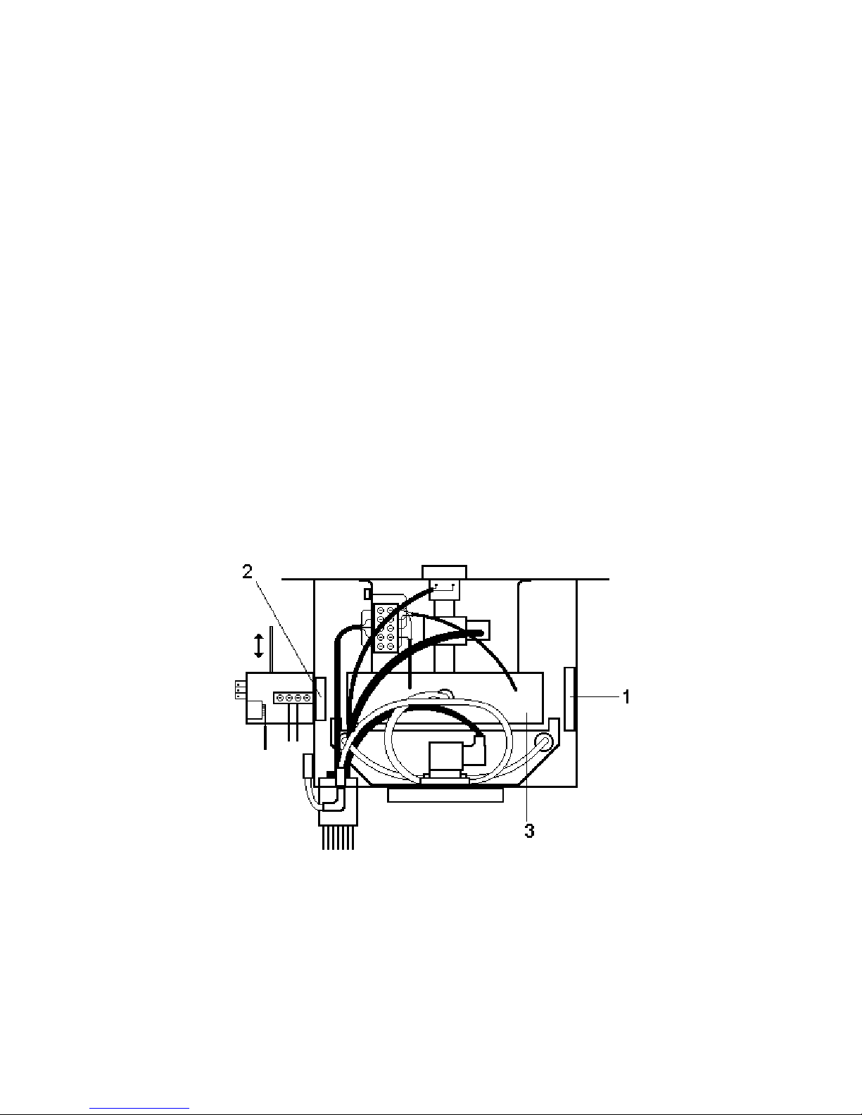
4 Moisten a piece of cotton with denatured alcohol and clean the mirror (1) and the two
glass plates (2) on the photoelectric cell.
5 We do not recommend using compressed air to clean the chamber. However,
sometimes it may be necessary to blow some air to remove soot. Pressure, leaving
the gun should never exceed 2/3 bar.
HIGHER PRESSURES CAN CAUSE PERMANENT DAMAGE TO THE DIFFERENTIAL
PRESSURE SENSOR.
Figure 6
Page 24

OPA 189 User Manual
24
10 TEMPERATURE READINGS
The TEMP/RPM display show the exhaust gases temperature.
The gas temperature sensor is an integrated circuit mounted on the inlet duct. You can
inspect it by removing the two screws that hold the fastening plate in position.
The temperature range is 2 - 150 °C.
11 PRESSURE/DEPRESSION MEASUREMENTS
The pressure sensor is of the differential type. It detects the difference in pressure
between the measuring chamber and the outside environment.
It is mounted directly on the chamber output pipe so that vibrations affecting the chamber
are damped.
The pressure sensor does not require any maintenance at all. NEVER use compressed air
to clean it; pressures of only 0.3 Bar can damage the sensor.
Pressure or depression in the chamber at the time of measure ment is printed on the test
results. Pressure or depression values exceeding 75 mm H20 are not allowed during the
tests; if this occurs, the control device stops the smoke meter and transmits an error
message on the printer.
12 POWER SUPPLY VOLTAGE
The smoke meter can be powered in two ways: from the mains, single phase, 220VAC
50Hz, or from a 13.8 VDC battery.
A 12 VDC battery installed on a vehicle with the engine running and with an efficient
recharging system, usually reaches an average of 13.8 DC. Therefore, this is considered
nominal voltage for the smoke meter.
Internal feeders stabilize voltage coming from the mains or a battery. Stabilization is better
than ±15% for both sources. Any greater changes are signalled by the respective LEDs on
the keypad.
Page 25
OPA 189 User Manual
25
13 PRINTER
The printer provides the initial Autotest and Autosetting message, results of the tests and
a series of error messages for the entire system.
PRINT and printer TEST functions can be obtained via the keypad.
To test the printer proceed as follows:
with the smoke meter switched off, press the PAPER ADV key, while keeping it pressed,
switch on the smoke meter using the ON/OFF key. The printer will send a message
showing the series of available characters; when this message is completed it can resume
normal operations.
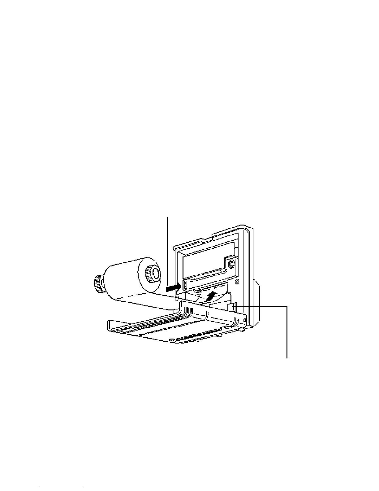
To replace the ink cartridge and paper, see the drawing below.
(Ink cartridge = EPSON ERC 09; Paper = w 56 mm; diam. 50 mm)
PRESS "PUSH" TO REMOVE USED CARTRIDGE
PRESS THE BUTTON UNTIL THE PAPER COMES OUT OF THE PRINTING MECHANISM
Figure 7
Page 26

OPA 189 User Manual
26
14 REPLACING FUSES
The smoke meter is equipped with two types of fuses: 0.5A/250 (5x20) for protections
towards the 220VAC mains, and 2A/250 (5x20) to protect the halogen lamp circuit. The
two fuses of 0.5A/250 are located in the filter/power switch unit. To replace it:
- disconnect the smoke meter from the 220V AC power supply.
- use your finger or a small screwdriver to remove the fusecarrier housing located above
the power plug.
- pull out the broken fuse and replace it with a new one.
- replace the fuse carrier.
- close the snap on cover.
The 2A/250 fuse is located on the power supply card (situated horizontally at the back of
the smoke meter); to replace it:
- switch off the smoke meter and disconnect it from the power supply.
- raise the hinged door on the cover.
- raise the protective cover.
- removed the blown fuse and replace it with a new one.
- replace the cover.
Page 27

OPA 189 User Manual
27
15 ERRORS
15.1 Function Errors Reported to the Operator
During the Autosetting, Autotest and measuring phases the smoke meter can and does
detect certain problems. The system software makes it possible to send the operator
warning messages and in serious cases, to shut down the machine.
In some cases, the system reports the error and even suggests possible remedies.
Typical error messages are:
ERRORE 01
FOTOCELLULA FUORI RANGE
Verificare pulizia parti
ottiche camera di misura
which means
ERROR 01
PHOTOELECTRIC CELL OUT OF RANGE
Make sure optical components
in the measuring chamber are clean.
ERRORE 02
LAMPADA SPENTA/BRUCIATA
Controllare lampada foto
cellula e fusibile lamp.
which means
ERROR 02
LAMP OFF/BURNT OUT
Check photoelectric cell lamp
and lamp fuse.
ERRORE 03
Misura opacità dei fumi
non consentita per Legge
Pressione nella camera
superiore a 75 mm acqua
which means
ERROR 03
Smoke measurement not allowed
by law.
Pressure in chamber exceeds
Page 28

OPA 189 User Manual
28
75 mm H2O
ERRORE 04
Misura opacità dei fumi
non conesntita per Legge
Depressione nella camera
superiore a 75 mm acqua
which means
ERROR 04
Smoke measurement not allowed
by law.
Depression in chamber exceeds
75 mm H2O.
etc.
As you can see, the first two messages give possible remedies, the other two do not
because it is clear that the problem is caused by gas adduction, therefore the sampling
point has to be shifted.
These are problems that you can solve more or less easily on your own without having to
call the Technical Service Department.
15.2 Function Errors That Cannot Be Immediately Resolved
In addition to the errors described above, the computer system makes it possible to detect
other errors that you cannot resolve by yourself.
This type of error shuts down the smoke meter and sends a message via the printer, such
as:
ERRORE S.A.1 - revolgersi al servizio assistenza tecnica
which means
ERROR S.A.1. - call the technical service department
ERRORE S.A.2. - rivolgersi al servizio assistenza tecnica
which means
ERROR S.A.2. - call the technical service department
etc.
Function errors are indicated by the letters S.A. and a progressive number. When you call
the technical service department, be sure to give the complete error code, with the
number. This lets the technician identify the error, even before he sees the machine.
NOTE: before calling the technical service department, switch off the smoke meter and
check to make sure that all cables and wires are properly connected. Then, switch it on
again and see if the error signal is still being given.
If there error signal persists, call the technical service department.
Page 29
OPA 189 User Manual
29
16 SMOKE-INTERCEPT SOLENOID VALVE MAINTENANCE
If the smoke meter is not used for long periods, and especially after heavy work cycles,
the solenoid valve may not open. This is due to the fact that, after the deposited gases
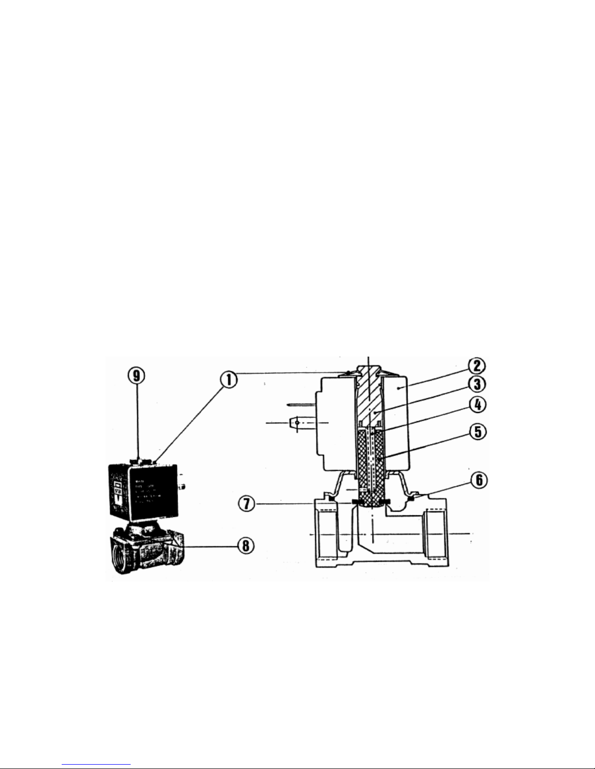
have dried, they hold back the seals restraining the core (7). In this case the smoke meter
can give an error signal or the display will read zero throughout the various tests.
A firm tap on the fitting for exhaust gas input (see Fig.2, item 2), on the head (9) or on the
brass body is usually sufficient to start the solenoid valve working again. If this does not
work, or each time you want to clean the solenoid valve circuits, proceed as folows:
a) Disconnect the smoke meter from the mains or battery power supply.
b) Open the measuring chamber.
c) Loosen the 4 screws (8), to access each one, rotate the coil (2) on its own axis. (The
coil can only be removed if you first release the cup spring (1), but this is usually not
necessary).
d) Raise the coil/pin unit.
e) Clean all the internal parts with a brush and compressed air at medium pressure (1-2
Atm).
f) Reassemble.
Figure 8
1) Cup spring 2) Coil
3) Guide unit 4) Core return spring
5) Core 6) OR Gasket
7) Seal 8) Screws M4x10
Page 30

OPA 189 User Manual
30
APPENDIX
CONVERSION TABLE:
Smoke readings expressed in PERCENTAGES (%) and ABSORPTION FACTOR K(m-1)
% K(m-1) % K(m-1)
05.0 = 0.13 54.0 = 1.94
10.0 = 0.26 55.0 = 2.00
15.0 = 0.41 56.0 = 2.05
20.0 = 0.55 57.0 = 2.11
25.0 = 0.71 58.0 = 2.17
30.0 = 0.89 59.0 = 2.23
31.0 = 0.93 60.0 = 2.29
32.0 = 0.96 61.0 = 2.35
33.0 = 1.00 62.0 = 2.42
34.0 = 1.03 63.0 = 2.49
35.0 = 1.07 64.0 = 2.55
36.0 = 1.11 65.0 = 2.62
37.0 = 1.15 66.0 = 2.70
38.0 = 1.19 67.0 = 2.77
40.0 = 1.28 68.0 = 2.85
41.0 = 1.31 69.0 = 2.93
42.0 = 1.36 70.0 = 3.01
43.0 = 1.40 71.0 = 3.09
44.0 = 1.45 72.0 = 3.18
45.0 = 1.49 73.0 = 3.27
46.0 = 1.54 74.0 = 3.37
47.0 = 1.59 75.0 = 3.46
48.0 = 1.63 76.0 = 3.57
49.0 = 1.68 77.0 = 3.67
50.0 = 1.73 78.0 = 3.79
51.0 = 1.78 79.0 = 3.90
52.0 = 1.83 80.0 = 4.02
53.0 = 1.89 90.0 = 5.76
MAXIMUM ALLOWED SMOKE LEVELS
Europe = 2.26 K(m-1) equal to 59.5%
Italy:
New automobiles and trucks: 50% equal to 1.73 K(m-1)
Used automobiles and trucks: 70% equal to 3.01 K(m-1)
New city buses: 45% equal to 1.49 K(m-1)
Used city buses: 65% equal to 2.62 K(m-1)
Page 31

OPA 189 User Manual
31
WARRANTY
This device was built with care and carefully inspected before it left the factory. It is
guaranteed for one year from the date of purchase by the final user.
To enjoy full rights under this warranty and avoid the risk of invalidation, you must mail a
copy of the Warranty Certificate to the factory within 10 days of the purchase date.
The warranty covers all defects in materials and workmanship.
The warranty does not cover: wiring, probes, the remote control unit and the accessories.
These items are subject to wear and their efficiency depends on how they are handled.
The warranty does not cover damage caused by accidents, impact or dropping the
instrument, or by negligence, improper use, non-compliance with the instructions and
improper storage.
If the device has such defects as to require technical serivce, you must return it to
Assemblad or an authorized service center. Shipping charges shall be covered by the
customer.
The warranty shall immediately become invalid if the device shows any signs of
tampering.
The sole court of jurisdiction for any disputes arising from the application and/or
intepretation of this warranty is the Court of Florence (Italy).
Page 32
OPA 189 User Manual
32
COPYRIGHT
by
ASSEMBLAD s.a.s.
via Marzabotto, 4
50013 Campi Bisenzio (Florence) ITALY
Tel. +39 / 55 / 890485 Fax +39 / 55 / 890496
Reproduction and/or disclosure prohibited
Release: February 1997
EMC 89/336
EN 50081-1 / EN 50082-1
EN 60204-1
File:M189gb10.doc
Edition: February 1997
and
are Registered Trademark
Page 33

OPA 189 User Manual
33
 Loading...