


User Manual
Online Option
ASSA ABLOY Hospitality
1

Copyrights
The information in this document is subject to change at the sole discretion of
ASSA ABLOY without notice.
Any use, operation or repair in contravention of this document is at your own risk.
ASSA ABLOY does not assume any responsibility for incidental or consequential
damages arising from the use of this manual.
All information and drawings in this document are the property of ASSA ABLOY.
Unauthorized use and reproduction is prohibited.
VingCard and Elsafe are registered trademarks of ASSA ABLOY.
ASSA ABLOY Hospitality
2

Table of contents
.................................................................................................6 FCC and IC statements
........................................................................................................................ 6FCC statements
........................................................................................................................ 7IC statements
................................................................................................................................................ 7
OEM responsibilities
................................................................................................................................................ 8
End product labeling
.................................................................................................9 1. Introduction
........................................................................................................................ 101.1 ZigBee standard
........................................................................................................................ 101.2 Server
........................................................................................................................ 101.3 Gateway
................................................................................................................................................ 11
1.3.1 Without DHCP server
........................................................................................................................ 121.4 Router
........................................................................................................................ 121.5 Endnode
........................................................................................................................ 121.6 Lock
........................................................................................................................ 121.7 Permit joining/Forbid joining
........................................................................................................................ 131.8 Discovery
........................................................................................................................ 131.9 Orphan join
........................................................................................................................ 131.10 SysMon and the client
........................................................................................................................ 151.11 Link quality
........................................................................................................................ 151.12 Abbreviations
.................................................................................................16 2. Installing the option
.................................................................................................17 3. Installing online devices
........................................................................................................................ 183.1 Installing a server
................................................................................................................................................ 18
3.1.1 TL Concentrator
3.8.1 Right-click menu choices for GWs
3.8.2 Right-click menu choices for RTs
3.8.3 Right-click menu choices for ENs
....................................................................................................................................... 19
3.1.1.1 TL Concentrator setup
....................................................................................................................................... 19
3.1.1.2 TL Concentrator monitor
........................................................................................................................ 203.2 Installing a gateway
........................................................................................................................ 223.3 Adding routers to a gateway
........................................................................................................................ 253.4 Adding endnodes to a router
........................................................................................................................ 263.5 Using routers as repeaters
........................................................................................................................ 273.6 Adding locks to gateways
........................................................................................................................ 273.7 Forcing parents
........................................................................................................................ 283.8 Right-click menus in SysMon
................................................................................................................................................ 29
................................................................................................................................................ 32
................................................................................................................................................ 33
.................................................................................................34 4. Online settings in the client
ASSA ABLOY Hospitality
3

........................................................................................................................ 344.1 Setting up door parameters in a hotel system
................................................................................................................................................ 34
4.1.1 Door ajar alarm
................................................................................................................................................ 35
4.1.2 Status
4.1.3 Miscellaneous
4.1.4 Alarms
4.1.5 Safes
....................................................................................................................................... 35
4.1.2.1 Intruder status
....................................................................................................................................... 35
4.1.2.2 Offline status
................................................................................................................................................ 36
................................................................................................................................................ 37
................................................................................................................................................ 38
........................................................................................................................ 384.2 Setting up door parameters in an access control system
........................................................................................................................ 394.3 Setting up operator templates in a hotel system
........................................................................................................................ 404.4 Setting up operator templates in an access control system
........................................................................................................................ 414.5 Preventing invalid staff card usage (only applicable for hotel systems)
.................................................................................................42 5. Issuing a ZigBee configuration card
.................................................................................................43 6. System operation
........................................................................................................................ 436.1 Events
................................................................................................................................................ 43
6.1.1 Acknowledge
................................................................................................................................................ 43
6.1.2 Retransmission
................................................................................................................................................ 43
6.1.3 Fallback
........................................................................................................................ 436.2 Online functionality
................................................................................................................................................ 44
6.2.1 Commands
6.2.2 Alarm list
6.2.3 Endnode list
6.2.4 Router list
6.2.5 Gateway list
....................................................................................................................................... 44
6.2.1.1 Buffered commands
................................................................................................................................................ 44
................................................................................................................................................ 45
................................................................................................................................................ 46
................................................................................................................................................ 47
........................................................................................................................ 476.3 Setting in construction mode
.................................................................................................48 7. Commissioning
........................................................................................................................ 487.1 Printing a status report
........................................................................................................................ 497.2 Pinging a door
........................................................................................................................ 507.3 Checking online status with card
.................................................................................................51 8. Power loss and hardware failure
........................................................................................................................ 518.1 Lock electronics
........................................................................................................................ 518.2 Endnode
........................................................................................................................ 528.3 Router
........................................................................................................................ 538.4 Gateway
........................................................................................................................ 538.5 Server
.................................................................................................54 9. Redundancy and recovery
........................................................................................................................ 549.1 Communication channel
................................................................................................................................................ 55
9.1.1 Automatic channel change
........................................................................................................................ 559.2 Recovery
................................................................................................................................................ 55
9.2.1 Polling
ASSA ABLOY Hospitality
4

................................................................................................................................................ 55
9.2.2 Fallback
.................................................................................................56 Appendix A: Online devices
........................................................................................................................ 56Gateway
........................................................................................................................ 57Router
.................................................................................................58 Appendix B: Mounting of gateway and router
.................................................................................................59 Appendix C: Example configurations
.................................................................................................61 Appendix D: Web interface for gateway
.................................................................................................62 Appendix E: Reset of gateway
.................................................................................................63 Appendix F: Gateway boot-up
.................................................................................................65 Appendix G: More about how the gateway finds the server
........................................................................................................................ 66Commissioning of gateways
................................................................................................................................................ 66
Single server - commissioning of gateways with DNS
................................................................................................................................................ 66
Multiple servers - commissioning of gateways with DNS
................................................................................................................................................ 67
Commissioning of gateways without DNS
........................................................................................................................ 67Switching to backup server
................................................................................................................................................ 67
Single server - switching to backup server with DNS
................................................................................................................................................ 67
Multiple servers - switching to backup server with DNS
................................................................................................................................................ 67
Switching to backup server without DNS
.................................................................................................68 Appendix H: Firmware upgrade
ASSA ABLOY Hospitality
5

FCC and IC statements
FCC (Federal Communications Commission) statements
These devices comply with Part 15 of the FCC Rules. Operation is subject to the following
two conditions:
(1) these devices may not cause harmful interference, and
(2) these devices must accept any interference received, including interference that may
cause undesired operation.
Important note: To maintain compliance with FCC´s RF exposure guidelines, this equipment
should be installed and operated with minimum distance 20 cm between the radiator and your
body. Use only the supplied antenna.
This equipment complies with FCC radiation exposure limits set forth for an uncontrolled environment.
These transmitters must not be co-located or operating in conjunction with any other antennas
or transmitters.
Changes or modifications not expressly approved by the party responsible for compliance could
void the user's authority to operate the equipment.
Note: This equipment has been tested and found to comply with the limits for a Class B digital
device, pursuant to part 15 of the FCC Rules. These limits are designed to provide reasonable
protection against harmful interference in a residential installation. This equipment generates,
uses and can radiate radio frequency energy and, if not installed and used in accordance with
the instructions, may cause harmful interference to radio communications. However, there is
no guarantee that interference will not occur in a particular installation. If this equipment does
cause harmful interference to radio or television reception, which can be determined by turning
the equipment off and on, the user is encouraged to try to correct the interference by one or
more of the following measures:
- Reorient or relocate the receiving antenna.
- Increase the separation between the equipment and receiver.
- Connect the equipment into an outlet on a circuit different from that to which the
receiver is connected.
- Consult the dealer or an experienced radio/TV technician for help.
The concerned end product must be labeled to say 'Contains FCC ID: WYV-EN110'.
The concerned end product must be labeled to say 'Contains FCC ID: WYV-EN055'.
The concerned end product must be labeled to say 'FCC ID: Y7V-683081067C1'.
The concerned end product must be labeled to say 'Contains FCC ID: WYV-RT067'.
The concerned end product must be labeled to say 'FCC ID: Y7V-683081066C1'.
The concerned end product must be labeled to say 'FCC ID: Y7V-GW683081066'.
ASSA ABLOY Hospitality
6
66 3081 004-22

IC (Industry Canada) statements
Name/Model
Gain
Impedance
Inverted F-antenna
3.0 dBi
50 ohm
These devices comply with Industry Canada licence-exempt RSS standard CAN ICES-3 (B)/NMB-3(B) B.
Operation is subject to the following two conditions:
(1) these devices may not cause interference, and
(2) these devices must accept any interference, including interference that may cause undesired
operation of the devices.
Les présents appareils sont conformes aux CNR d’Industrie Canada applicables aux appareils radio
exempts de licence. L’exploitation est autorisée aux deux conditions suivantes:
(1) les appareils ne doivent pas produire de brouillage, et
(2) l’utilisateur des appareils doit accepter tout brouillage radioélectrique subi,
même si le brouillage est susceptible d’en compromettre le fonctionnement.
Important note: To comply with Industry Canada RF radiation exposure limits for general population,
the antennas used for these transmitters must be installed such that a minimum separation distance
of 20 cm is maintained between the radiator (antenna) and all persons at all times and must not be
co-located or operating in conjunction with any other antenna or transmitter.
Under Industry Canada regulations, these radio transmitters may only operate using an antenna of a
type and maximum (or lesser) gain approved for the transmitter by Industry Canada. To reduce potential
radio interference to other users, the antenna type and its gain should be so chosen that the equivalent
isotropically radiated power (e.i.r.p.) is not more than that necessary for successful communication.
These radio transmitters IC8231A-EN110, IC8231A-EN055, IC9514A-683081067C1, IC8231A-RT067,
IC9514A-683081066C1 and IC9514A-683081066 have been approved by Industry Canada to operate
with the antenna types listed below with the maximum permissible gain and required antenna
impedance for each antenna type indicated. Antenna types not included in this list, having a gain
greater than the maximum gain indicated for that type, are strictly prohibited for use with these devices.
The term "IC" before the equipment certification number only signifies that the Industry Canada
technical specifications were met.
Le terme "IC" devant le numéro de certification signifie seulement que les specifications techniques
Industrie Canada ont été respectées.
OEM responsibilities
The endnode module has been certified for integration into products only by OEM integrators under
the following conditions:
1. The antenna must be installed such that a minimum separation distance of 20cm is maintained
between the radiator (antenna) and all persons at all times.
2. The transmitter module must not be co-located or operating in conjunction with any other
antenna or transmitter.
As long as the two conditions above are met, further transmitter testing will not be required.
However, the OEM integrator is still responsible for testing their end-product for any additional
compliance requirements required with these modules installed (e.g., digital device emissions,
PC peripheral requirements, etc.).
Important note: In the event that these conditions can not be met (for certain configurations or
co-location with another transmitter), then Industry Canada certification is no longer considered valid
and the IC Certification Number can not be used on the final product. In these circumstances, the OEM
integrator will be responsible for re-evaluating the end products (including the transmitter) and obtaining
a separate Industry Canada authorization.
ASSA ABLOY Hospitality
7
66 3081 004-22

End product labeling
The endnode module is labeled with its own IC Certification Number. If the IC Certification Number is not
visible when a module is installed inside another device, then the outside of the device into which the module
is installed must also display a label referring to the enclosed module. In that case, the final end product
must be labeled in a visible area with the following:
'Contains IC: 8231A-EN110'
'Contains IC: 8231A-EN055'
The OEM of the respective module must only use the approved antenna listed above, which have been
certified with this module. The OEM integrator has to be aware not to provide information to the end user
regarding how to install or remove this RF module or change RF related parameters in the user’s manual
of the end products.
ASSA ABLOY Hospitality
8
66 3081 004-22

1. Introduction
Figure 1: Example of online configuration. Several other configurations are possible;
see Appendix C for some examples.
With the online option, the locks can both send and retrieve information. Commands
can be sent from the front desk (hotel systems)/company reception (access control
systems) to the lock. e.g., in hotel systems a guest can change rooms without
needing to go to the reception. Events are directly sent to the application server.
This chapter describes the online network topology all the way from the server to
the lock. Commands sent from the server to a lock will pass through the items in the
order they are mentioned. Answers will pass through the same items but in the
opposite direction.
Note: The most information in this manual is common for hotel systems and access
control systems. In some cases there are however specific sections, which is clearly
stated in the heading.
Note: Some online functions require the Online advanced option; see the section
about options in the client user manual for details.
ASSA ABLOY Hospitality
9
66 3081 004-22
1.1 ZigBee standard
The online option is based on the ZigBee standard, a standard for transmission of
data via radio. The ZigBee devices have low power consumption and the standard is
aimed at control applications with relatively low data rate. Below are some basic facts
for the standard:
based on IEEE 802.15.4 (Open ISM 2.4GHz band; ISM = industrial, scientific
and medical)
16 channels spread spectrum (DSSS, Direct Sequence Spread Spectrum)
250kbit/s (~2kbit/s @ 1% duty-cycle)
consists of a virtually unlimited number of small networks (PANs, personal area
networks)
1.2 Server
The server is the manager of the whole network for a property. It can manage a
virtually unlimited number of gateways. All commands sent from the server are
encrypted.
1.3 Gateway
The gateways connect to the server via TCP/IP and automatically adjusts to
10 or 100 Mbit/s networks. The gateway starts by retrieving an IP address via
DHCP (Dynamic Host Configuration Protocol) and then automatically finds the server.
Note: The DHCP protocol is specified according to the standard RFC 2131.
Note: A ping is sent to each gateway once an hour. The statistics is evaluated once
a day. An alarm is triggered if more than one per cent of the pings fail. The statistics
is shown in the System Settings report in the client.
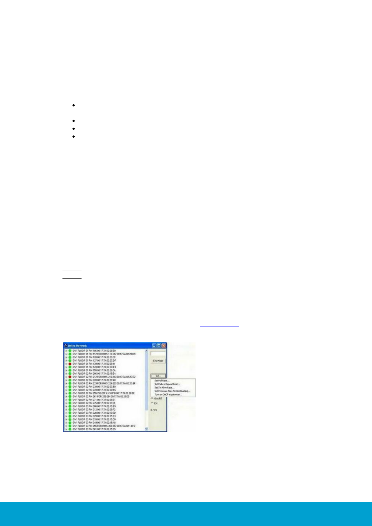
If DHCP has previously been turned off manually, it can be enabled again by clicking
the Set button in the Online Network dialog of SysMon (System Monitor) and
choosing Turn on DHCP in gateway. See section 1.10 for more information
about SysMon.
Figure 2
ASSA ABLOY Hospitality
10
66 3081 004-22

The dialog Enter MAC address will be shown; fill it in and click OK.
Figure 3
The gateway contains functionality for coordination of a PAN (Personal Area
Network). The PAN is a wireless network that communicates on the 2.4GHz band.
The gateway allows routers (see section 1.4) and endnodes (see section 1.5) to join
the PAN and assigns network addresses. Each ZigBee node has a unique 64-bit IEEE
address similar to Mac addresses used in TCP/IP.
The gateway chooses which of the 16 channels in the 2.4GHz band the nodes in
the PAN should use.
The gateway is powered either over Ethernet or by a power adapter.
The total number of gateways is virtually unlimited.
The maximum theoretical limit of endnodes per PAN is high, but a practical limit
is some hundred. In most cases, only some ten to 20 endnodes will be
connected to each gateway. However, this can change due to the building
construction, materialwise etc.
The gateway can have either five routers or 15 endnodes connected as direct
descendants.
See Appendix A for more information about the gateway, including a
detailed picture.
See Appendix B for preferred way of mounting the gateway.
See Appendix C for configuration examples.
1.3.1 Without DHCP server
1. The IP address on the gateway will change to an IP address in the range
169.254.1.0 – 169.254.254.255; this IP address range is based on the
zero config standard.
2. Have a web browser available, to reach a web interface where the gateway
parameters can be changed. Follow the steps below:
- Press the F button on the gateway for a short while (see in Appendix A where
the button is located). The status LED on top of the gateway will blink yellow.
- Use Wireshark to find out the zero config IP address of the gateway.
- Enter the zero config IP address in the web browser (http://ipaddress) to reach
the web interface (ZigBee Gateway Setup page) where the desired changes can
be made. Note: See Appendix D e.g. screenshot and more details about the web
interface. Note: For a reset to factory default values, press and hold the F button
while powering up the gateway.
ASSA ABLOY Hospitality
11
66 3081 004-22

1.4 Router
A router acts either as a repeater for range extension, or as a parent for endnodes.
It will also act as a buffer for messages sent to endnodes connected to the router.
Routers are externally powered.
The router can have either five routers or 15 endnodes connected as direct
descendants.
There can be a maximum of five hops down the gateway; i.e. gateway – router
– router – router – router – endnode. This limits the physical coverage of a
PAN. Important: Even though it is possible to have five hops, it is
recommended to have maximum three hops, i.e. gateway - router router - endnode. The link quality index (LQI) should be at least 30%.
See section 1.11 for more information about the LQI.
See Appendix A for more information about the router, including a detailed picture.
See Appendix B for preferred way of mounting the router.
See Appendix C for configuration examples.
1.5 Endnode
An endnode is built into each lock. It is optimized for low power consumption.
The parent router will act as a buffer for commands from the server. A command
sent from the server to a lock will be sent from the gateway to the lock’s parent
router. The command will be sent through the routers that may be located between
the gateway and the lock’s parent router. Any message sent from the lock will be
passed on to the server through the parent router, any intermediate routers and the
gateway. Messages from the lock are sent instantly. The total number of endnodes is
virtually unlimited.
1.6 Lock
The locks are the destination for commands and the source of events.
1.7 Permit joining/Forbid joining
In order to prevent nodes from joining randomly, 'permit joining' can for each PAN
only be made at one router or its 'parent gateway' at a time. When a node is to be
joined to the PAN, 'permit joining' must be made at the router or gateway that shall
be its parent. When the node has joined, 'forbid joining' should be made at the
parent. 'Forbid joining' will automatically be made on the parent after 15 minutes
in case it is forgotten. Note: It is only possible to make 'permit joining' at one RT
per PAN at a time. If you make 'permit joining' at one RT and then at another RT
in the same PAN, the first RT will automatically make 'forbid joining'.
ASSA ABLOY Hospitality
12
66 3081 004-22

The commands for 'permit joining' and 'forbid joining' are sent from SysMon.
The 'permit joining'/'forbid joining' states of routers can also be toggled by pressing
the F1 button. The LED on the router indicates 'permit joining' by fast blinking;
short blink every 0.5 seconds. 'Forbid joining' is indicated by slow blinking; short
blink every two seconds. See Appendix A for a router picture with buttons, LED etc.
1.8 Discovery
Discovery is the process when a node shall join a PAN. It starts by the node
broadcasting a discovery message. Any plausible parent will answer and the
node will join the one on which “permit joining” has been made, provided that
it is within range.
Routers make discovery when given a reset while the F1 button is being pressed;
see Appendix A for a router picture with buttons.
An endnode makes discovery when a Discovery card is presented at the lock; see
chapter 5 Issuing a ZigBee configuration card. When the card is presented, the lock
will chirp once and/or a show a green LED signal (depending on lock model). If the
endnode in the lock is busy at the moment, there will instead be a tick sound and/or
a very short green LED signal. In this case, make a new try by presenting the
Discovery card at the lock again.
1.9 Orphan join
As it can take up to three hours for the endnodes to get online after recovery from
a power cut, there is an Orphan Join card that will initiate an orphan join when
presented at a lock; see chapter 5 Issuing a ZigBee configuration card. When the
card is presented at the lock, the lock will chirp once and/or a show a green LED
signal (depending on lock model). If the endnode in the lock is busy at the moment,
there will instead be a tick sound and/or a very short green LED signal. In this case,
make a new try by presenting the Orphan Join card at the lock again.
1.10 SysMon and the client
The System Monitor (SysMon; found in the folder where the server software has
been installed) is used for managing the online network. In SysMon all connected
gateways, routers, endnodes etc are shown. Depending on what operator template
that the logged on operator belongs to, the operator is authorized to perform
different operations in SysMon.
Note: If the distributor is going to log on to SysMon, system manager must be logged
on first.
ASSA ABLOY Hospitality
13
66 3081 004-22
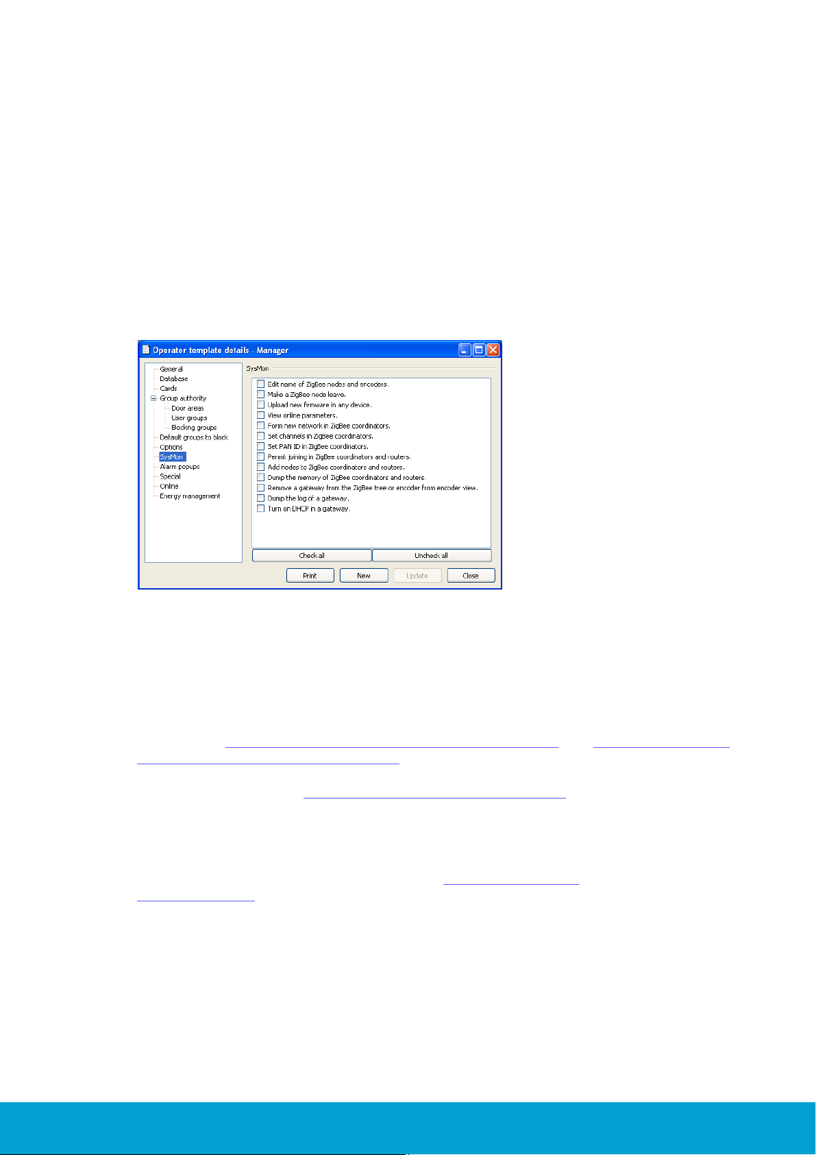
To set up SysMon authorities:
Figure 4
1. Double click on Operator templates under the Lists tab in the navigation window
of the client.
2. Mark an existing operator template and click Properties, or click Add to create
a new operator template.
3. In the Operator Template Details dialog, click SysMon in the left pane.
4. Mark the applicable checkboxes for operations that operators belonging to the
template should be allowed to perform in SysMon.
5. If an existing operator template was updated with SysMon information, click
Update and Close. If a new operator template was created, enter applicable
information for the operator template under the other panes General, Database
etc and then click Save and Close.
Online settings and commands are made in the client.
If a dialog in the client should be refreshed due to online changes, this is shown with
a * in the dialog caption. Click the Refresh button in the dialog.
Different operator templates can be given different authorities for online commands;
see sections 4.3 Set up operator templates in a hotel system and 4.4 Set up operator
templates in an access control system respectively.
For online settings, see chapter 4 Online settings in the client.
For online commands, see the user manual for the client (the sections about
online commands for a door and about commands under the Online tab).
For supervision of the system, see chapters 6 System operation and
7 Commissioning.
ASSA ABLOY Hospitality
14
66 3081 004-22
1.11 Link quality
Figure 5
Figure 6
Figure 7
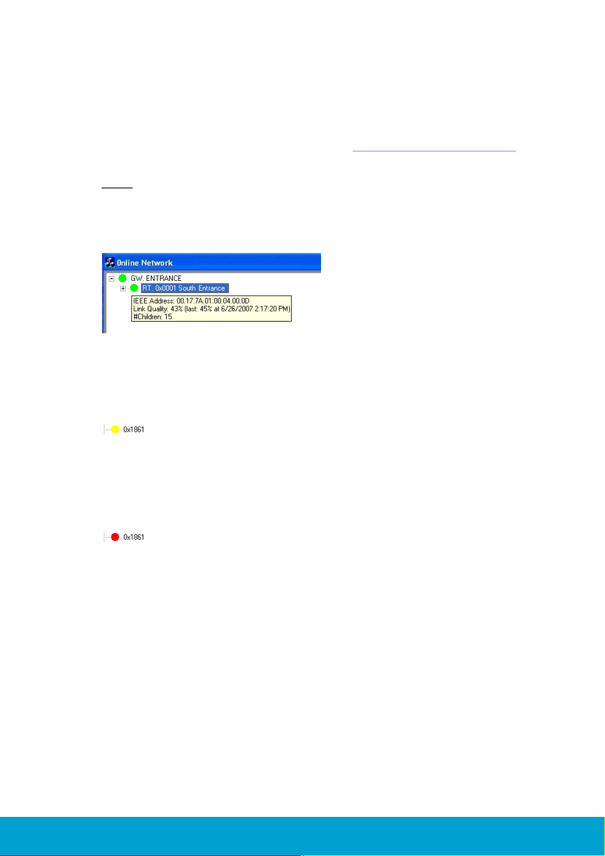
The Link Quality Index (LQI) is an average percentage that should not be below 30%.
It is displayed when the mouse hovers over a node in the SysMon Online Network
view; see example in the screenshot below. See section 3.2 Installing a gateway for
information about how to log on to SysMon and find the Online Network view.
Note: The LQI value which is shown when the mouse hovers over a node is not an
instantaneous value but an average; the last instantaneous value, with timestamp,
is however shown within parantheses after the average. To get an instantaneous
value of the LQI, right click on a router or endnode in the SysMon Online Network
view and choose Get User Description.
The LQI is valid for the link between the node and its parent.
If the LQI is below 30%, the dot in front of the node in SysMon is yellow; see
example in Figure 6.
If the LQI is below 15%, the dot in front of the node is SysMon is red; see example
in Figure 7.
1.12 Abbreviations
In the rest of this user manual, the following abbreviations are used:
GW = gateway
RT = router
EN = endnode
PAN = personal area network
ASSA ABLOY Hospitality
15
66 3081 004-22

2. Installing the option
Figure 8
If the option has been ordered together with the software, it is included in the license
code and will be set in the software when the license code is entered.
If the option should be added to the system at a later occasion, when the license code
has already been entered and system ID is therefore set, an option code is used instead.
Several software options can be included in one option code. An operator with the
authority to handle option codes must be logged on. Normally, options are set by the
system manager or the distributor.
When ordering the option, the system code must be communicated to the
ordering department:
1. Double click on System settings under the Reports tab in the navigation
window to find the system code. System settings is available even if you are not
logged on.
2. Communicate your system code to the order department; see order
acknowledgement for phone number and e-mail address. The system code can also
be entered in the Ordering web page when making the order.
To install the option:
1. When you have got your option code, go to Tools/Option code.
2. Enter the option code and click Apply.
ASSA ABLOY Hospitality
16
66 3081 004-22

3. Installing online devices
The online devices were designed to allow for maximum flexibility during installation.
There are no particular location specifications as long as the devices are within
reasonable range of each other and good radio communication can be attained.
Generally, the range is however around 20 metres or through a wall. The range
of the devices depends to large extent on the building material(s) in the
surroundings. As much effort as possible should be made to securely install each
device in a location where it will be dry, cool, and undisturbed, yet still maintain
good radio contact with its parent or children.
Important: The ZigBee communication can be disturbed by e.g. Wi-Fi networks;
always make sure to have as long distances as is physically possible between ZigBee
devices and other radio equipment. If this still causes problems at a site, automatic
channel change can be enabled. See more information about automatic channel
change in section 9.1.1.
This section will discuss the installation methods for each device in the system as
well as options for forcing devices to connect to specific parent devices.
Software requirement:
Hotel system: version 1.9.0 or later
Access control system: version 1.6.0 or later
ASSA ABLOY Hospitality
17
66 3081 004-22

3.1 Installing a server
Figure 9
The application server must be connected to the same network that the
GW devices will be connected to.
The application server must have the online option installed; see chapter 2
for details.
1. Before you install the first GW device, you must add a ZigBee gateway to the
device list in the software (double click on Devices under the Lists tab in the
navigation window and click Add to add a new device) using the following
parameters:
2. When the fields have been filled in according to Figure 9 (port 7799 is pre-filled
as default when choosing 'ZigBee gateway' at Type), click Save and Close.
Note: If desired, mark the checkbox 'Wizard mode' to get more detailed help.
Note: The same device is used for all GWs.
For testing and commissioning purposes it is a good idea to have either a laptop with
the server software installed which you can use to directly connect to gateways as
they are installed, or a laptop with a connection to the live application server. This
will allow you to test radio signal strength as you are installing the devices on each
floor so issues can be addressed immediately.
Note: The network information is stored in the GWs and not in the laptop.
3.1.1 TL Concentrator
TL Concentrator is a utility for simplifying the setup of a firewall when the GWs are
located on a different network. TLConcentrator runs on the ZigBee server and listens
for GWs on one port and forwards all traffic to the application server on another port.
All traffic from the application server is sent to the correct GW. In this way, the
firewall will only have to be set up to allow sockets from the ZigBee server.
The alternative would be to set up the firewall to allow sockets for every GW.
This would add implications, especially when adding or exchanging GWs.
ASSA ABLOY Hospitality
18
66 3081 004-22

3.1.1.1 TL Concentrator setup
Figure 10
Figure 11
The application server is set up to listen for GWs on port 7799. This is where
TLConcentrator will connect. TLConcentrator is set up to listen for GWs on port 7798
and to open sockets on the application server using port 7799.
To set up these parameters:
1. Go to Start/Run.
2. Browse to the installation folder, mark TLConcentrator.exe and click Open.
3. Add /config
Note: There should be a space before /
4. Click OK.
A Configuration dialog will be shown.
1. Let the default 7798 be at Listen Port.
2. State the host’s IP address at Host Address.
3. Let the default 7799 be at Host Port.
3.1.1.2 TL Concentrator monitor
It is possible to monitor the traffic through TLConcentrator using
TLConcentrator.exe /monitor.
1. Go to Start/Run.
2. Browse to the installation folder, mark TLConcentrator.exe and click Open.
3. Add /monitor
Note: There should be a space before /
4. Click OK. The following dialog (with example statistics) is shown.
ASSA ABLOY Hospitality
19
66 3081 004-22

3.2 Installing a gateway
Figure 12
Figure 13
Power and network connections should be made in a manner that will reduce the
chances of the device being unplugged.
The GW is powered by 5VDC using a plug in wall power adapter, or via power
over Ethernet.
For network connectivity, the GW requires an available Ethernet port and a
patch cord.
1. Open the System Monitor (SysMon), which is used for managing the online
network. To open SysMon, double click on SysMon.exe in the installation
folder.
2. Log on to SysMon: go to File/Log on and enter user ID and password.
At 'Operator card', choose the applicable card encoder. Click Enter.
3. If it is not open already, open SysMon's Online Network view at View/
Online Network. The Online Network view of SysMon shows all connected
GWs, RTs and ENs. Several useful commands are available by right clicking on
nodes; see sections 3.8.1-3.8.3 for more information about the different
commands.
4. Mount the GW in a convenient, out of the way location using the
5. Connect the network cable and power cable to the GW.
6. After approximately 30 seconds the GW will announce itself to the
7. Right click on the new GW to bring up the device option menu and choose
Edit Name.
ASSA ABLOY Hospitality
VELCRO® strip.
server and appear as a new GW in the Online Network tree in SysMon.
20
66 3081 004-22

Figure 14
8. Name the GW something meaningful – it should generally indicate the GW's
Figure 15
Figure 16
location or coverage area.
9. Right click on the GW and select Form new network to make sure that the GW is
reset and gets a PAN ID.
ASSA ABLOY Hospitality
21
66 3081 004-22
 Loading...