


IC Radio Standards Specification: RSS-210
ACS Report Number: 11-0071.W06.11.A
Certification Exhibit
FCC ID: U4A-SCYICLS2
IC: 6982A-SCYICLS2
FCC Rule Part: 15.225
Manufacturer: Assa Abloy, Inc.
Model: P2-IM/IKM
Manual
5015 B.U. Bowman Drive Buford, GA 30518 USA Voice: 770-831-8048 Fax: 770-831-8598
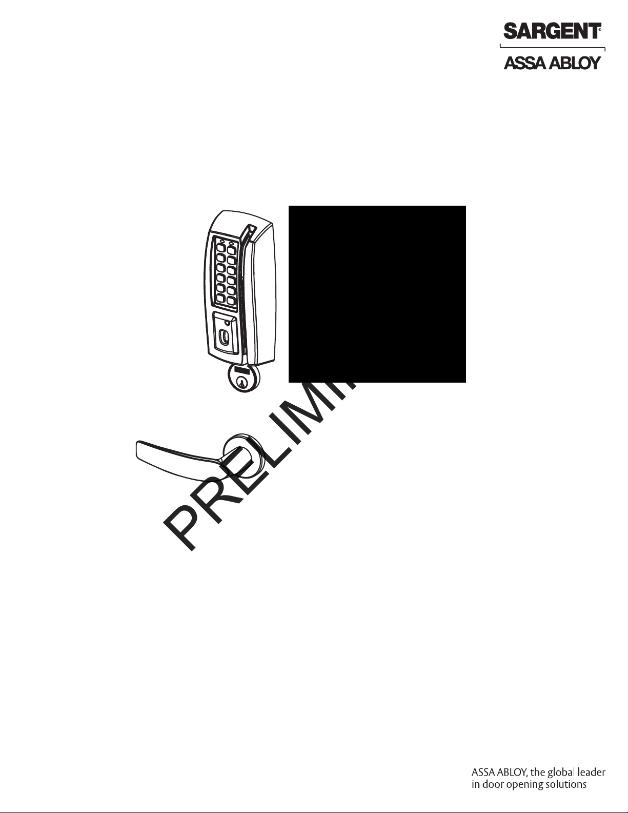
P2
PRELIMINARY
PASSPORT 1000
Mortise Lock
Installation Instructions
A8011E
12/10
Copyright 2010, Sargent Manufacturing Company, an ASSA ABLOY Group company.
All rights reserved. Reproduction in whole or in part without the express written
permission of Sargent Manufacturing Company is prohibited.

Table of Contents
PRELIMINARY
Warning ...................................................................................2
1
2
General Description
3
Hardware Specifications
4
Electronic Specifications
5
Parts Breakdown
6
Installation Instructions
7
Operational Check
1
Warning
FCC
NOTE: This equipment has been tested and found to comply with the limits for a Class B digital device, pursuant to
Part 15 of the FCC Rules. These limits are designed to provide reasonable protection against harmful interference in a
residential installation.
This equipment generates, uses, and can radiate radio frequency energy and, if not installed and used in accordance
with the instructions, may cause harmful interference to radio communications. However, there is no guarantee that
interference will not occur in a particular installation. If this equipment does cause harmful interference to radio or television reception, which can be determined by turning the equipment off and on, the user is encouraged to try to correct
the interference by one or more of the following measures:
• Reorient or relocate the receiving antenna.
• Increase the separation between the equipment and receiver.
• Connect the equipment into an outlet on a circuit different from that to which the receiver is connected.
• Consult the dealer or an experienced radio/TV technician for help.
Changes or modifications to this unit not expressly approved by the party responsible
for compliance could void the user’s authority to operate the equipment.
.................................................................3
.........................................................3
.........................................................3
.....................................................................4
..........................................................7
................................................................14
Industry Canada:
Statement: The term “IC:” before the radio certification number only signifies that Industry Canada
technical specifications were met.
This Class B digital apparatus meets all requirements of the Canadian Interference Causing Equipment Regulations.
Operation is subject to the following two conditions: (1) this device may not cause harmful interference, and (2) this
device must accept any interference received, including interference that may cause undesired operation.
Cet appareillage numérique de la classe B répond à toutes les exigences de l’interférence canadienne
causant des règlements d’équipement. L’opération est sujette aux deux conditions suivantes: (1) ce
dispositif peut ne pas causer l’interférence nocive, et (2) ce dispositif doit accepter n’importe quelle
interférence reçue, y compris l’interférence qui peut causer l’opération peu désirée.
Copyright © 2010, Sargent Manufacturing Company, an ASSA ABLOY Group company. All rights reserved.
Reproductions in whole or in part without express written permission of Sargent Manufacturing Company is prohibited.
10/10/10
1-800-810-WIRE • www.sargentlock.com • A8078A
To comply with “Fire Listed” doors, the batteries must be replaced with alkaline batteries only.
!

Passport 1000 Series P2 Mortise Lock
PRELIMINARY
2
General Description
The SARGENT Passport Series v.P2 Mortise Lock is available with either an HID® Prox 125 kHz or 13.56 MHz iCLASS®
technology reader.
Lock is a new breed of electronic lock, providing access control with magnetic swipe and optional Proximity
Reader and/or Keypad, as well as detailed audit capabilities.
• Using WiFi technology and coupled with third party software, the P2 Mortise lock offers a complete,
integrated access control system.
• The Passport 1000 P2 operates on six (6) “AA” alkaline batteries and may be used for both indoor and
outdoor applications.
Note: A weather-protective gasket is recommended for outdoor applications.
HID and iCLASS are registered trademarks of HID Global Corporation.
3
Hardware Specifications
• Complete lockset with on-board memory
• Magnetic swipe standard with optional 125 kHz
Proximity Reader (specify PRX-), 13.56 MHz
reader (specify IKM-), and/or keypad (specify
KP-)
• ADA compliant
• Easily retrofits existing Passport 1000 door
preps (mortise)
• Latch - Stainless steel
• Optional deadbolt - Stainless steel
• Guardbolt - Stainless steel, non handed
• Handing (RH/RHR/LH/LHR) must be specified,
but is easily field-reversible without opening
the lock case
Designed specifically for the campus market, the SARGENT Passport 1000 P2 WiFi Mortise
• Case - 12 gauge heavy duty wrought steel
• Outside lever is unlocked through access
control credentials only
• Cylinder retracts latchbolt (and deadbolt)
• Inside lever retracts latch and deadbolt simultan
ously
• Lock furnished for 1-3/4” doors.
For other thicknesses, Consult factory.
• UL Listed (3 hr.)
• Outside lever controlled by any combination of keypad,
magnetic swipe, iCLASS, prox (proximity) reader, or mechanical cylinder
• Outside lever for iCLASS controlled by HID iCLASS
credential or other 13.56 MHz credential (such as CSN, Chip
Serial Number, read only supported, including
MiFare, DesFire, and Felica)
4
Electronic Specifications
• Wireless (WiFi 802.11 b/g) online, batteryoperated
• 2,400 users per lock; 10,000 event audit
trail
• Multiple time zone and holiday access
scheduling
• First-In unlock configuration, either by
time or by user (selectable)
• Input Power: DC 9V, 1.5A (6 AA alkaline
batteries or optional hard-powered)
• Uses existing Magstripe keycards (track 2)
• Magnetic Stripe Card Coercivity: HiCo (4000
Oersted) or LoCo (300 Oersted)
• Supports HID 125 kHz prox or 13.56 MHz iCLASS
credentials (26 - 39 bit); supports CSN reads for
other common 13.56 MHz cards, including MiFare, DesFire, and FeliCa
• AWE Prefix Available for WPA2, PEAP and EAPTLS Wireless Encryption Support
1-800-810-WIRE • www.sargentlock.com • A8011E 3
Copyright © 2010, Sargent Manufacturing Company, an ASSA ABLOY Group company. All rights reserved.
Reproductions in whole or in part without express written permission of Sargent Manufacturing Company is prohibited.
12/15/10

Passport 1000 Series P2 Mortise Lock
9
10
12
13
10
P2
Inside
10
11
Outside
PRELIMINARY
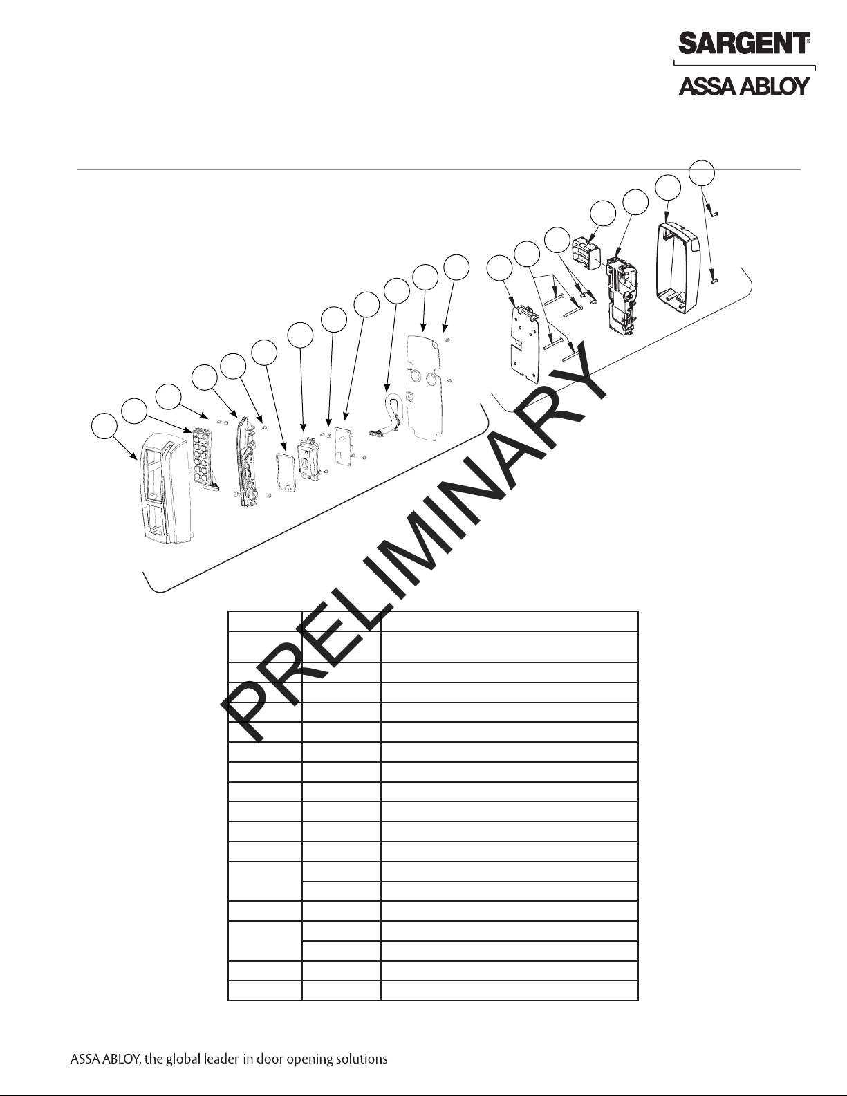
5
Parts Breakdown
P2 WiFi Lock with Magnetic Card Swipe With or Without Keypad
10
10
9
9
8
5
7
5
6
5
4
3
2
1
10
11
11
12
12
Inside
13
13
10
14
Outside
ITEM No. PART No. DESCRIPTION
1 52-0757 Lens (Cliplite)
2
3 52-0760 Light Pipe (Cliplite)
4 52-3594 Slim Style Keypad Assembly
5 01-9299 #4-40 x 3/16” Phillips Pan Head Screw
6 52-4243 Swipe Reader Assembly
7 52-0745 Online Interface PCB
8 52-3209 Harness Assembly
9 52-0748 Inside Mounting Plate
10
11 01-1146 #8-32 x 3/8” Phillips Flat Head Screw
12 52-4246 Modular Component
13
Copyright © 2010, Sargent Manufacturing Company, an ASSA ABLOY Group company. All rights reserved.
Reproductions in whole or in part without express written permission of Sargent Manufacturing Company is prohibited.
14 01-4421 #8-32 x 1/2” T-20 Torx Pan Head Screw
52-0738 Outside Passport Escutcheon Only (Magnetic Swipe and Keypad)
52-0739 Outside Passport Escutcheon Only (Magnetic Swipe)
77-0168 #8-32 x 1-7/8” Phillips Flat Head Screw
01-1176 #8 x 3/8” Phillips Flat Head Wood Screw
52-3592 Inside Escutcheon Assembly
12/15/10
4 1-800-810-WIRE • www.sargentlock.com • A8011E
Passport 1000 Series P2 Mortise Lock
PRELIMINARY
Parts Breakdown (Continued)
P2 WiFi Lock with Magnetic Card Swipe, 125 kHz and Keypad
12
10
10
11
9
5
9
8
7
3
6
5
3
4
3
2
1
10
13
11
12
14
Inside
13
15
10
16
Outside
ITEM No. PART No. DESCRIPTION
1 52-1103 Outside Passport Escutcheon only
2 52-3593 Slim Style Keypad Assembly
3 01-9299 #4-40 x 3/16” Phillips Pan Head Screw
4 52-4243 Swipe Reader Assembly
5 52-1106 Prox Reader Gasket
6 52-4206 Antenna Assembly
7 52-0745 Online Interface PCB
8 52-3209 Harness Assembly
9 52-1109 Back Plate
10 52-0748 Inside Mounting Plate
11
12 01-1146 #8-32 x 3/8” Phillips Flat Head Screw
13
14 52-4263 AWE Controller Assembly Kit
15
16 01-4421 #8-32 x 1/2” T-20 Torx Pan Head Screw
77-0168 #8-32 x 1-7/8” Phillips Flat Head Screw
01-1176 #8 x 3/8” Phillips Flat Head Wood Screw
52-0751 Battery Cartridge (Only)
52-4247 Modular Component and Battery Cartridge Kit
52-3592 Inside Escutcheon Assembly
(Magnetic Swipe, Keypad and Proximity Reader)
Copyright © 2010, Sargent Manufacturing Company, an ASSA ABLOY Group company. All rights reserved.
Reproductions in whole or in part without express written permission of Sargent Manufacturing Company is prohibited.
1-800-810-WIRE • www.sargentlock.com • A8011E 5
12/15/10

Passport 1000 Series P2 Mortise Lock
PRELIMINARY
Parts Breakdown (Continued)
P2 WiFi Lock with Magnetic Card Swipe, 13.56 MHz and Keypad
8
7
6
4
5
4
3
4
9
2
1
4
4
10
ITEM No. PART No. DESCRIPTION
1 52-4402 Outside Mask Assembly
2 52-1255 Outside Escutcheon - iCLASS
3 52-3593 Slim Style Keypad Assembly
4 01-9299 #4-40 x 3/16” Machine Screw
5 52-4243 Swipe Reader Assembly
6 52-4401 iCLASS Module Assembly
7 52-3209 Harness Assembly
8 52-4410 iCLASS Harness
9 52-1109 Back Plate
10
Copyright © 2010, Sargent Manufacturing Company, an ASSA ABLOY Group company. All rights reserved.
Reproductions in whole or in part without express written permission of Sargent Manufacturing Company is prohibited.
01-9300 #4-32 x 5/16” Plastite Screw
12/15/10
6 1-800-810-WIRE • www.sargentlock.com • A8011E

Passport 1000 Series P2 Mortise Lock
PRELIMINARY
Parts Breakdown (Continued)
8200 Series Mortise Lock
5
4
6
3
11
10
9
8
7
14
15 16 17
ITEM PART No. DESCRIPTION
1 See catalog #41 Cylinder (1-1/8” Minimum Length)
2 13-0140 Cylinder Compression Spring
3 See catalog 1KB-1 Cylinder Rosette
4 See catalog Mortise Lockbody
5 77-2592 130 KB Thumbturn for Deadbolt Functions Only
6 See catalog Inside Lever Handle
7 See catalog Outside Lever Assembly
8 82-0368 Spindle
9 82-3088 Inside Lever/Knob Adapter Plate Assembly
10 01-1495 #8-32 X 5/8 Machine Screw
11 82-0612 Non Loosening Wave Washer
12 See catalog Mortise Rose
13 82-0347 Spindle Spring
14 01-1019 #12-24 X 1/2” Machine Screw
15 01-2299 12 X 1-1/4 Wood Screw
16 82-0578 Outside Front Plate (Electrical, Latchbolt & Guardbolt)
82-0579 Outside Front Plate (Electrical, Deadbolt, Latchbolt and Guardbolt)
17 01-1028 #8-32 X 1/4 Machine Screw
12
13
Copyright © 2010, Sargent Manufacturing Company, an ASSA ABLOY Group company. All rights reserved.
Reproductions in whole or in part without express written permission of Sargent Manufacturing Company is prohibited.
1-800-810-WIRE • www.sargentlock.com • A8011E 7
12/15/10

Passport 1000 Series P2 Mortise Lock
PRELIMINARY
6
Installation Instructions
1 Door Preparation
A. Verify Hand and Bevel of Door
Stand on outside of locked door when determining door hand.
Left Hand
Hinges Left.
Open Inward.
“LH”
B. Verify Product Label
• (IKM-) (KP-) P2- (PRX-) 82276 x Rose & Lever x Finish x Hand
• (IKM-) (KP-) P2- (PRX-) 82277 x Rose & Lever x Finish x Hand
• (IKM-) (KP-) P2- (PRX-) 82278 x Rose & Lever x Finish x Hand
• (IKM-) (KP-) P2- (PRX-) 82279 x Rose & Lever x Finish x Hand
Note: KP- is for the optional Keypad and PRX- is for the optional Proximity Reader
Left Hand
Reverse Bevel
Hinges Left.
Open Outward.
“LHRB”
Right Hand
Hinges Right.
Open Inward.
“RH”
Right Hand
Reverse Bevel
Hinges Right.
Open Outward.
“RHRB”
C. Door Preparation
Refer to template A7950 for wood and metal doors.
Outside of Door
Through Bolt Holes
Raceway for Power
Controller Cutout
Cylinder Hole
Lever Handle Holes
Copyright © 2010, Sargent Manufacturing Company, an ASSA ABLOY Group company. All rights reserved.
Reproductions in whole or in part without express written permission of Sargent Manufacturing Company is prohibited.
Inside of Door
Through Bolt Holes
Inside Mounting Plate
Mounting Holes
Raceway for Power
Controller Cutout
Thumb Turn Location
(Deadbolt Functions Only)
Lever Handle Holes
Mortise
Pocket
12/15/10
(8200)
8 1-800-810-WIRE • www.sargentlock.com • A8011E

Passport 1000 Series P2 Mortise Lock
PRELIMINARY
2 How to Change Hand of Lockbody
A. Reverse Lock Hand
Red surface of locking piece must face the outside/
locked side of door. To rotate locking piece (Fig. 2A):
1. Position lock body with red surface of locking
piece visible.
2. Insert blade type screwdriver into locking piece
slot to rotate locking piece toward back of lock
body.
3. Rotate the locking piece 180° until RED surface is
on opposite side.
Note: Red indicates locked side (outside). Wire
harness MUST exit through
the inside/non-cylinder side of the lockbody.
B. Retaining Ring
Make sure the plastic retaining ring is seated correctly (Fig. 2B):
1. The wires and the plastic retaining ring must
be located on the non-cylinder side.
2. Orient the plastic retaining ring so that the
word
Bottom is located at the bottom of the cylinder
hole.
3. Route the wires from the top of the cylinder
hole
into the slot on the top of the plastic retaining
ring,
NOT through the retaining ring.
Connector
Ring Terminal
Slot
Plastic
Retaining
Ring
Inside of Door
Latchbolt
C. Reverse Latch Hand
Beveled surface of latchbolt must face strike.
The deadlatch is self adjusting.
To change the hand of the latchbolt:
1. Insert the blade of a slotted screwdriver (>1/4”)
into the spade shape slot behind latch.
2. Rotate the screwdriver 90° to push latchbolt out
until back of bolt clears lock case front.
3. Rotate latchbolt 180° until the latchbolt
drops back into the lockbody.
Note: Latch cannot be unscrewed.
Locking Slide
Red on locked side
Fig. 2A
1-800-810-WIRE • www.sargentlock.com • A8011E 9
Push In
Right Hand
Lock Shown
Copyright © 2010, Sargent Manufacturing Company, an ASSA ABLOY Group company. All rights reserved.
Reproductions in whole or in part without express written permission of Sargent Manufacturing Company is prohibited.
12/15/10

3
PRELIMINARY
Install Lock Body
1. Feed the wires first through the mortise pocket
and out the inside prep, followed by the
lockbody (Fig. 3A).
2. The wires from the lockbody exit the inside
door prep through the mortise pocket (Fig. 3B).
3. Loosely secure the lockbody in the door with
two #12 x 1-1/4” wood screws or
#12-24 x 1/2” machine screws.
Must feed
the harness first,
followed by
the lockbody.
(2) #12 x 1-1/4” Long
Flat Head Wood Screw
for Wood Doors
Passport 1000 Series P2 Mortise Lock
Mortise Lockbody
Connector and
Grounding Lug
(2) #12-24 x 1/2” Long
Flat Head Machine Screw
4
Install Cylinder
for Metal Doors
1. Slide cylinder through the spring and rosette/collar and screw into lockbody, rotating the cylinder clockwise.
Cylinder should be flush with rosette/collar.
Note: SARGENT logo must be horizontal
and on the top of the cylinder (Fig. 4B).
2. Secure the cylinder by tightening cylinder
clamp screw located above the deadbolt.
3. Using the key, verify that the key retracts
the
latchbolt (and deadbolt).
Position cylinder so that the SAR-
GENT logo is right-side up.
Fig. 3A
Fig. 3B
Align cylinder groove
with tapped hole,
then tighten set screw
to hold lock cylinder.
Correct Incorrect
Copyright © 2010, Sargent Manufacturing Company, an ASSA ABLOY Group company. All rights reserved.
Reproductions in whole or in part without express written permission of Sargent Manufacturing Company is prohibited.
12/15/10
10 1-800-810-WIRE • www.sargentlock.com • A8011E
Fig. 4B

Passport 1000 Series P2 Mortise Lock
PRELIMINARY
5
Install Inside and Outside Levers
1. Slide the outside lever and spindle assembly through the door and lockbody.
2. Using the inside adapter plate and spindle, secure loosely with (2) #8-32 screws.
Note: Position threaded hole on the inside adapter to align with lever hole.
3. Tighten the lockbody screws on edge of door.
4. After the lockbody screws are tightened, tighten both inside adapter screws.
5. Position and attach rose over inside adapter.
6. Position and secure inside lever to the
inside adapter with set screw.
Outside Lever Assembly
Fig. 5A
6
Deadbolt Functions Only (82276 & 82277)
1. Insert alignment tool (supplied) into lock body thumb
turn.
2. Slide back plate over tool and make level.
3. Secure back plate to door with two (2) #6 x 3/8”
round head
wood screws or #6-32 x 3/8” round head machine
screws.
4. Dispose of tool, position thumb turn over back plate
(Fig. 6A) and secure with #6-32 x 1/4” flat head
screw.
Note: Thumb turn should cover screw head when
deadbolt is retracted.
Refer to instructions (A5675G) included in package
included with lock.
Mortise Lock Body
Connector and Ground
Ring Terminal
Rose
Inside Adapter Plate
Inside Lever
Back Plate
#6 x 3/8” Round Head
Wood Screws
#6-32 x 3/8” Round
Head Machine Screws
Thumb Turn
Alignment Tool
Fig. 6B Detail
1-800-810-WIRE • www.sargentlock.com • A8011E 11
Fig. 6A
#6-32 x 1/4”
Flat Head Screw
Copyright © 2010, Sargent Manufacturing Company, an ASSA ABLOY Group company. All rights reserved.
Reproductions in whole or in part without express written permission of Sargent Manufacturing Company is prohibited.
12/15/10

Passport 1000 Series P2 Mortise Lock
PRELIMINARY
7
Install Gasket (Optinal)
Note: Optional, for non-fire rated doors only.
For non-fire rated door applications, an optional gasket may be
used as a weather seal between the escutcheon and the outside
door surface.
Peel off adhesive backing and attach to outside escutcheon.
Gasket
Outside
Passport
Trim
8
Install Outside Escutcheon and Mounting Plate Assembly
1. Insert the mounting posts through holes as shown.
2. On the inside of the door, position the mounting plate
over the indicated holes.
Note: Feed controller and keypad cables feed through side opening
(Fig. 8A).
Cable and ground ring terminal from lockbody
feeds from bottom (Fig. 8A and 8B).
3. Attach ground ring terminal lock body to bottom right
corner using one #8-32 x 1-7/8” flat head machine screw.
Make sure it is positioned upright (Fig. 8A).
4. Insert other three #8-32 x 1-7/8” flat head machine
screws and tighten, fastening the outside escutcheon
to the door (Fig. 8B).
Lock Ground
IMPORTANT: If the following step is skipped,
the product will not be UL-compliant:
5. Attach two (2) #8 x 3/8” flat head wood screws for
Lockbody Cable
wood doors or (2) #8-32 x 3/8” flat head machine
screws for metal doors (Fig. 8C).
Outside
Passport
Trim
Mounting Plate
(4) #8 - 32 x 1-7/8” Flat
Head Machine Screws
Fig. 7A
Mounting Plate
Reader Cable
(iCLASS only)
Controller/Reader
Cable
Position ground
ring terminal upright, then tighten
screw.
Fig. 8B
Reader Cable
(iCLASS only)
Reader/Controller Cable
Attach ground
wire to bottom
right screw
Fig. 8C
Copyright © 2010, Sargent Manufacturing Company, an ASSA ABLOY Group company. All rights reserved.
Reproductions in whole or in part without express written permission of Sargent Manufacturing Company is prohibited.
12/15/10
Lock Cable
Fig. 8A
12 1-800-810-WIRE • www.sargentlock.com • A8011E
(2) #8 - 3/8” Flat Head
Wood Screws OR
(2) #8 - 3/8” Flat Head
Machine Screws

Passport 1000 Series P2 Mortise Lock
PRELIMINARY
9
Install Inside Module Component Assembly
Insert bottom of Module Component Assembly first (Fig.
9A), then clip top of Assembly to backplate, verifying
both tabs attached securely.
Tabs
Outside of Door
Fig. 9A
10
Attach Connectors
Secure the following connectors onto the circuit board (Fig.
10A and 10B):
1. Secure the 10-pin lock body assembly connector.
2. Secure the 24-pin keypad/card reader connector.
3. Secure 9-pin reader cable (iCLASS only).
Notes:
• Connectors go on only one way.
• Do not force and do not offset connectors.
• Be sure the connectors are completely seated (flush).
24-pin from
Outside Trim
Detail 10B
9-pin Reader Cable
(iCLASS Only)
Fig. 10A
10-pin from
Lockbody
Fig. 10B Detail
1-800-810-WIRE • www.sargentlock.com • A8011E 13
Copyright © 2010, Sargent Manufacturing Company, an ASSA ABLOY Group company. All rights reserved.
Reproductions in whole or in part without express written permission of Sargent Manufacturing Company is prohibited.
12/15/10

11
PRELIMINARY
Install Battery/Battery Pack
1. Place (6) “AA” batteries into the compartment being careful to align polarity (- & +) properly.
2. Insert battery pack and click into place, making
sure polarity terminals on the battery pack are
correctly oriented (Fig. 11A).
Passport 1000 Series P2 Mortise Lock
Fig. 11A
12
Attach Outside Front Plate
1. Position inside escutcheon as shown (Fig.
12A).
Verify that all wires are positioned within the
escutcheon to avoid pinching.
2. Attach escutcheon with (2) #8-32 x 1/2” T-20
Torx pan head screws.
3. Straighten escutcheon and tighten securely.
DO NOT OVERTIGHTEN.
Copyright © 2010, Sargent Manufacturing Company, an ASSA ABLOY Group company. All rights reserved.
Reproductions in whole or in part without express written permission of Sargent Manufacturing Company is prohibited.
(2) #8-32 x 1/2”
Torx Screws
Fig. 12A
12/15/10
14 1-800-810-WIRE • www.sargentlock.com • A8011E

Passport 1000 Series P2 Mortise Lock
PRELIMINARY
13
Attach Outside Front Plate
Attach front plate with (2) #8-32 X 1/4” flat head screws (Fig. 13A).
(2) #8-32 x 1/4”
Flat Head Screws
Fig. 13A
1-800-810-WIRE • www.sargentlock.com • A8011E 15
Copyright © 2010, Sargent Manufacturing Company, an ASSA ABLOY Group company. All rights reserved.
Reproductions in whole or in part without express written permission of Sargent Manufacturing Company is prohibited.
12/15/10

7
PRELIMINARY
Installation Instructions
IMPORTANT: Be sure to test functions prior to closing door.
In all cases, perform the following checks:
1. Ensure that inside lever retracts latch (and deadbolt for
deadbolt functions).
• For units with cylinders, the following checks apply:
Insert key into cylinder and rotate:
a. There should be no friction against lock case,
wire harness, or any other obstructions. If friction
or binding occurs, readjust cylinder and wiring
harness to eliminate issues.
b. The key should retract the latch and the key
should rotate freely.
c. The key should extend and retract the deadbolt.
• For units without a keypad, add card using LCT
software and test.
• For units with a keypad, add pin and card using LCT
software and test.
2. LED signalling:
• After using a valid credential, a green flash followed
by three fast amber flashes indicates a low power
condition.
Check the battery voltage.
If the voltage is low, replace the batteries.
• If the batteries die, the lock will flash rapid amber
for approximately one minute.
After that, the lock will no longer be functional.
3. When you have completed the tests, close the door,
ensuring latchbolt and deadbolt fully extend into strike
plate without binding.
SARGENT Manufacturing
100 Sargent Drive
New Haven, CT 06511 USA
800-810-WIRE (9473) • www.sargentlock.com
Founded in the early 1800s, SARGENT® is a market leader in locksets, cylinders, door closers, exit devices,
electro-mechanical products and access control systems for new construction, renovation, and replacement applications.
The company’s customer base includes commercial construction, institutional, and industrial markets.
Copyright © 2010, Sargent Manufacturing Company, an ASSA ABLOY Group company. All rights reserved.
Reproduction in whole or in part without the express written permission of Sargent Manufacturing Company is prohibited.
ASSA ABLOY is the global leader in door opening solutions, dedicated to
satisfying end-user needs for security, safety and convenience.
A8011E -12/10
 Loading...