


IC Radio Standards Specification: RSS-210
Certification Exhibit
FCC ID: U4A-SCYICLS1
IC: 6982A-SCYICLS1
FCC Rule Part: 15.247 / 15.225
ACS Project Number: 10-0345
Manufacturer: Assa Abloy
Model: N2-IA/IK
Manual
5015 B.U. Bowman Drive Buford, GA 30518 USA Voice: 770-831-8048 Fax: 770-831-8598
v.N2
Profile Series
v.N2 with
Aperio™
Technology
Mortise Lock
Installation Instructions
A8078A
04/11
Copyright 2011, Sargent Manufacturing Company, an ASSA ABLOY Group company.
All rights reserved. Reproduction in whole or in part without the express written
permission of Sargent Manufacturing Company is prohibited.
Table of Contents
1
Warning ...................................................................................2
2
General Description .................................................................3
3
Specifications ..........................................................................3
4
System Overview .....................................................................3
5
Parts Breakdown .....................................................................4
6
Lock Installation ......................................................................6
7
Operational Check ................................................................14
8
Lock LED Indications ............................................................15
1
Warning
FCC:
This equipment has been tested and found to comply with the limits for a Class B digital
device, pursuant to Part 15 of the FCC Rules. These limits are designed to provide reasonable
protection against harmful interference in a residential installation. This equipment generates,
uses, and can radiate radio frequency energy and, if not installed and used in accordance with
the instructions, may cause harmful interference to radio communications. However, there is
no guarantee that interference will not occur in a particular installation. If this equipment does
cause harmful Interference to radio or television reception, which can be determined by turning
the equipment off and on, the user is encouraged to try to correct the interference by one or
more of the following measures:
• Reorient or relocate the receiving antenna.
• Increase the separation between the equipment and receiver.
• Connect the equipment into an outlet on a circuit different from that to which the receiver is Connected.
• Consult the dealer or an experienced radio/TV technician for help.
Industry Canada:
This Class B digital apparatus meets all requirements of the Canadian Interference Causing
Equipment Regulations. Operation is subject to the following two conditions: (1) this device
may not cause harmful interference, and (2) this device must accept any interference received,
including interference that may cause undesired operation.
Warning: Changes or modifications to this device not expressly approved by ASSA
ABLOY could void the user’s authority to operate the equipment.
Cet appareillage numérique de la classe B répond à toutes les exigences de l’interférence
canadienne causant des règlements d’équipement. L’opération est sujette aux deux conditions
suivantes: (1) ce dispositif peut ne pas causer l’interférence nocive, et (2) ce dispositif
doit accepter n’importe quelle interférence reçue, y compris l’interférence qui peut causer
l’opération peu désirée.
“This equipment complies with FCC radiation exposure limits set forth for an uncontrolled
environment. This equipment should be installed and operated with minimum distance 20cm
between the radiator and your body. This transmitter must not be co-located or operating in
conjunction with any other antenna or transmitter.”
Under Industry Canada regulations, this radio transmitter may only operate using an antenna
of a type and maximum (or lesser) gain approved for the transmitter by Industry Canada. To
Copyright © 2011, Sargent Manufacturing Company, an ASSA ABLOY Group company. All rights reserved.
Reproductions in whole or in part without express written permission of Sargent Manufacturing Company is prohibited.
04/08/11
1-800-810-WIRE • www.sargentlock.com • A8078A
reduce potential radio interference to other users, the antenna type and its gain should be so
chosen that the equivalent isotropically radiated power (e.i.r.p.) is not more than that necessary
for successful communication.
Profile Series v.N2 Mortise Lock
2
General Description
The SARGENT® Profile Series v.N2 lock with Aperio™ Technology makes it easy and cost-effective to bring
access control to additional doors. It uses local wireless communication between the lock and an Aperio hub
to connect to an access control system, eliminating the greatest cost and inconvenience of traditional access
control – the wiring at the door. The Profile Series v.N2 includes HID® iCLASS® 13.56 MHz smart card technology, and all technology features are supported by the physical security of SARGENT ANSI/BHMA Grade 1
hardware.
This product is operated by six (6) “AA” alkaline batteries. SARGENT mortise locks are designed with quality
components to provide high security, performance and durability.
The Aperio mortise lock may be used for both indoor and outdoor applications. A weather-protective
gasket is recommended for outdoor applications.
3
4
Specifications
Lock
• IEEE 802.15.4 UHF interface
• iCLASS technology
• AES 128 bit encryption
iCLASS Card Requirements
• Supports HID 13.56 MHz iCLASS contactless
• ISO14443 standard memory types
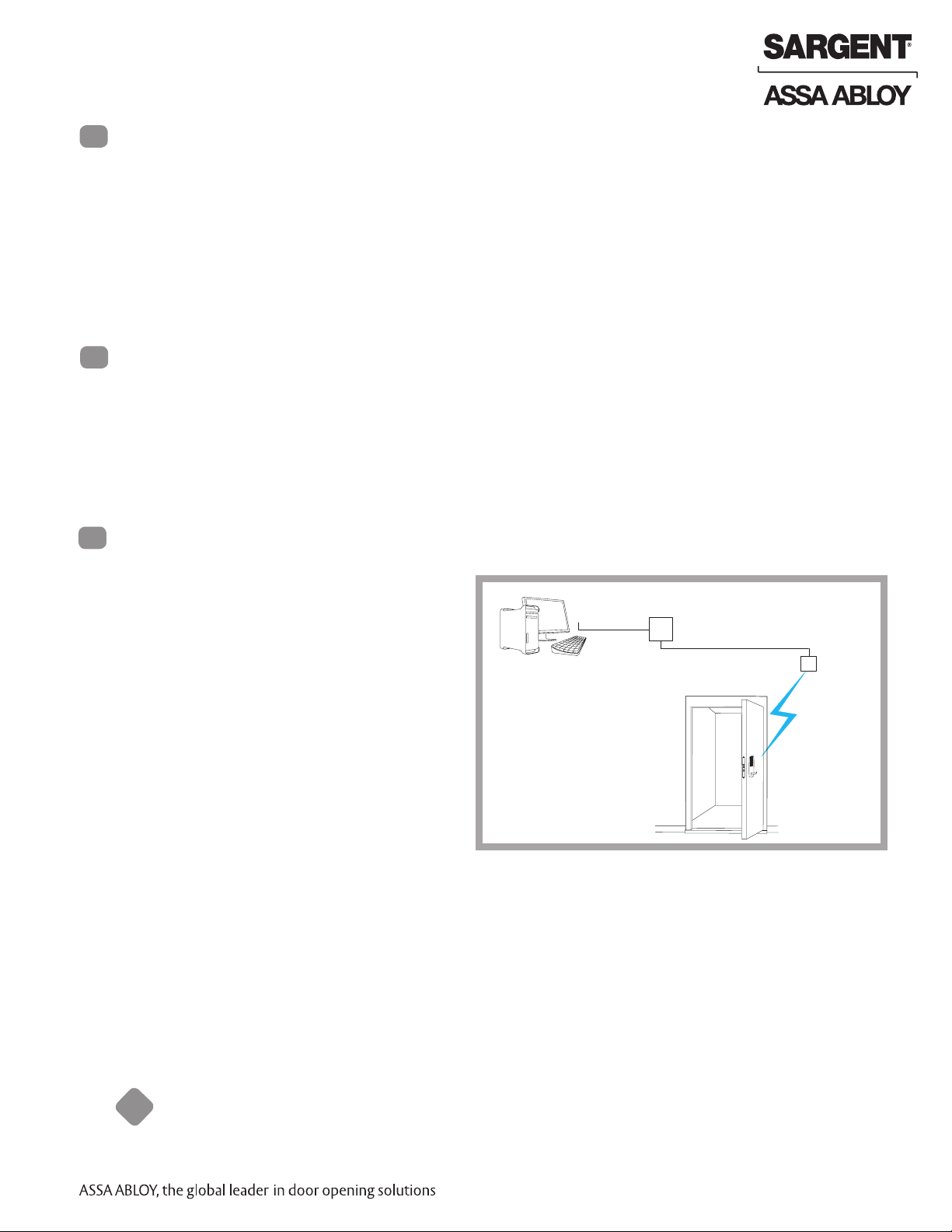
System Overview
When a user presents a supported credential to
the lock, the Aperio system is designed to send
the credential wirelessly to the Aperio Hub. The
Aperio Hub (wired through RS-485 or Wiegand)
then communicates with an EAC (Electronic
Access Control) system. The EAC system provides
the access decision to the Communication Hub
where access to the lock is either granted or
denied.
credentials (full authentication, all formats)
Electronic Access
Control System
TCP/IP
Access Control Panel
RS-485/Wiegand
Aperio Hub
IEEE 802.15.4
(2.4GHz)
To comply with “Fire Listed” doors, the batteries must be replaced with alkaline batteries only.
!
Warning: SARGENT Mfg. Co. Profile Series v.N2 locksets utilizing a door position switch (DPS) are not rated for,
or intended for use in life safety applications.
1-800-810-WIRE • www.sargentlock.com • A8078A 3
Copyright © 2011, Sargent Manufacturing Company, an ASSA ABLOY Group company. All rights reserved.
Reproductions in whole or in part without express written permission of Sargent Manufacturing Company is prohibited.
04/08/11
5
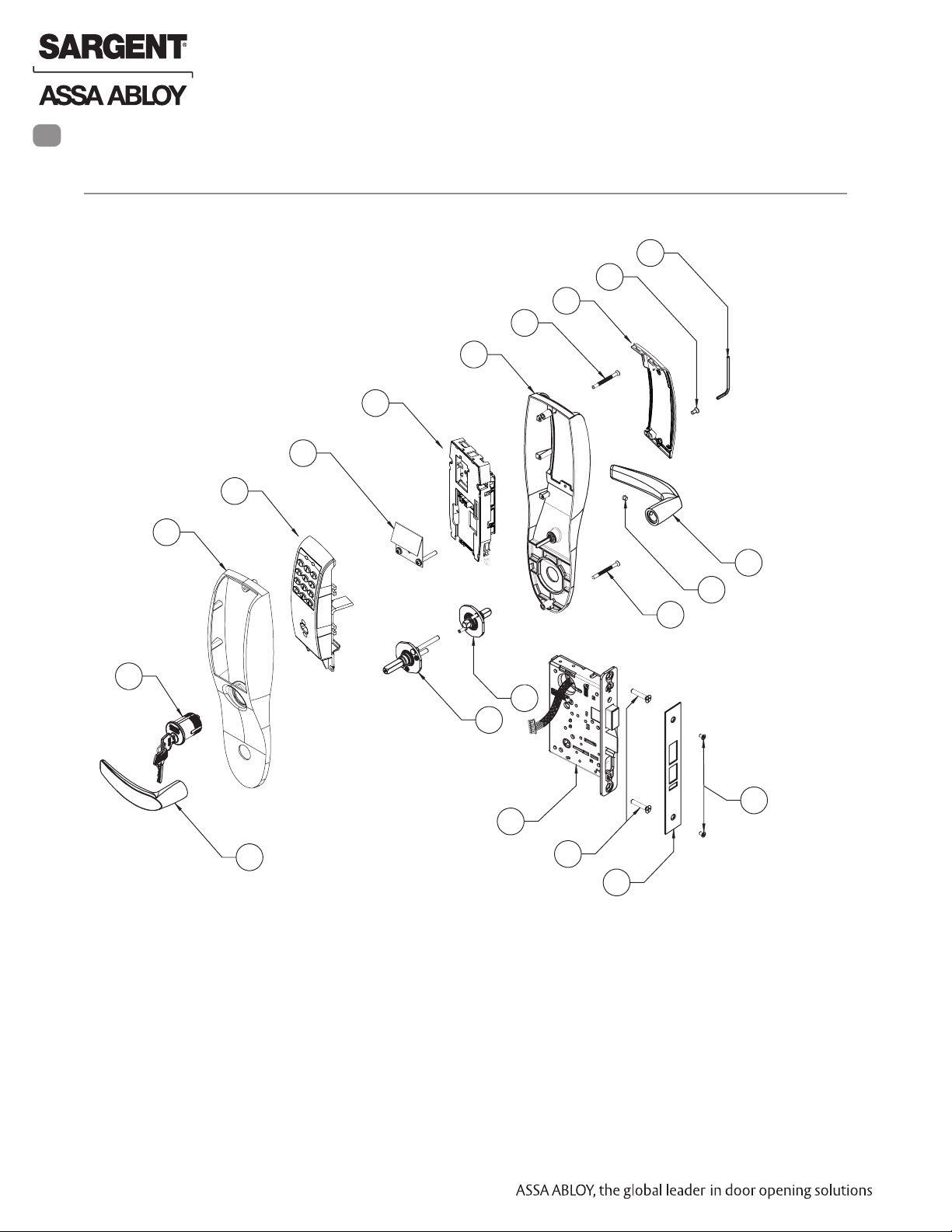
Parts Breakdown
13.56 MHz iCLASS
5
9
5
Profile Series v.N2 Mortise Lock
9
8
7
9
4
3
2
10
9
16
11
12
9
7
13
1
15
14
15
Copyright © 2011, Sargent Manufacturing Company, an ASSA ABLOY Group company. All rights reserved.
Reproductions in whole or in part without express written permission of Sargent Manufacturing Company is prohibited.
04/08/11
4 1-800-810-WIRE • www.sargentlock.com • A8078A
Profile Series v.N2 Mortise Lock
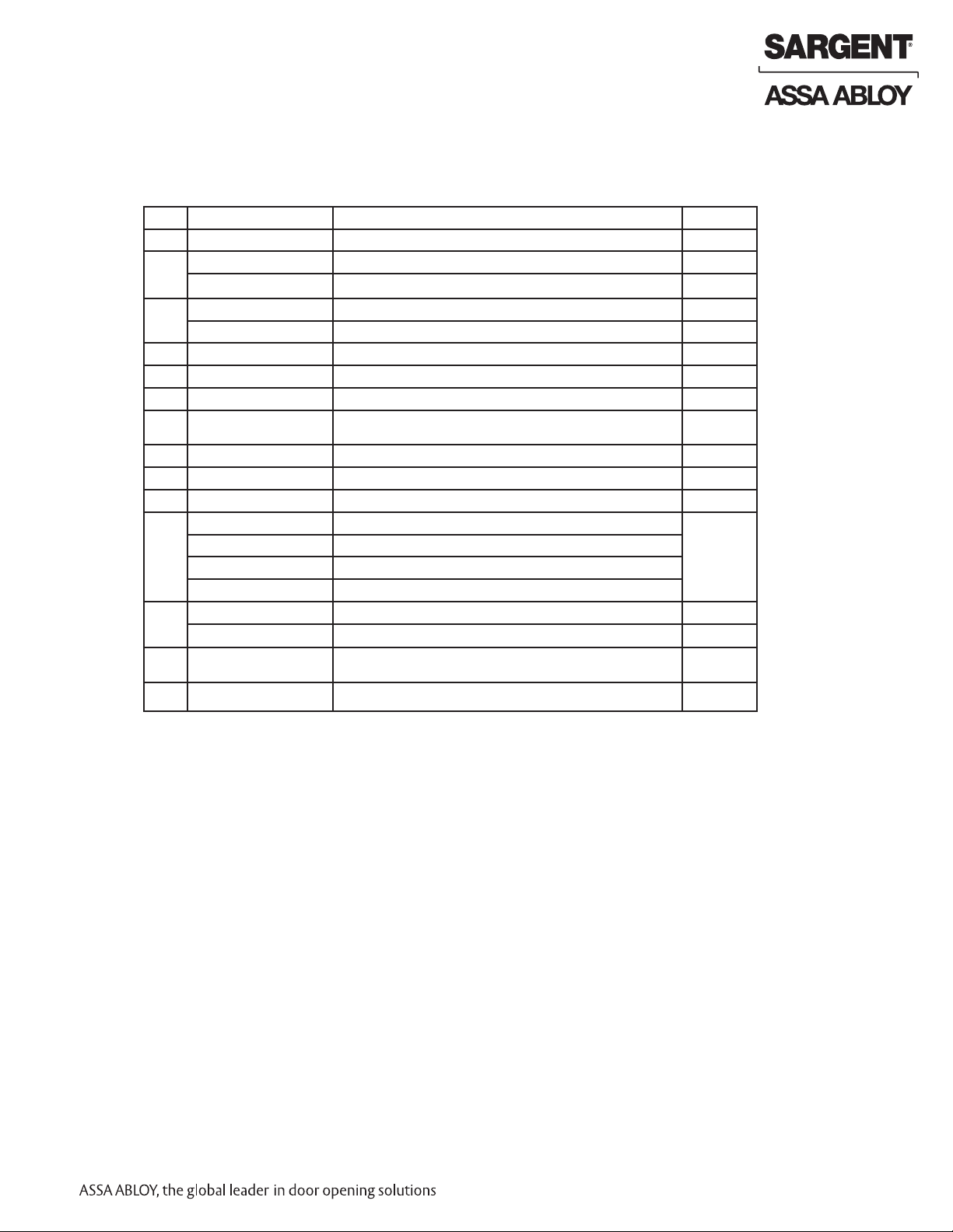
Parts Breakdown 13.56 MHz iCLASS (Continued)
ITEM
1 Outside Lever Reference 8200 Catalog for available levers 1
2 Inside Lever Reference 8200 Catalog for available levers 1
3 82-0495 O/S Escutcheon only with Cylinder 1
4 82-0492 Inside Escutcheon only without Thumb Turn 1
5 52-5291 Aperio Electronic Replacement Pack, 13.56 MHz iCLASS 1
7 52-4340 Battery Cover Assembly 1
8 01-1212 Security Screw 1
9 52-2427 Profile Screw Pack - Specify Finish (Includes: Fire Stop Plate, Trim
10 Consult Factory Lever Handle Screw (Depends on Lever Style) 1
11 Consult Factory Inside Adapter Assembly (Depends on Lever Style) 1
12 Consult Factory Outside Adapter Assembly (Depends On Lever Style) 1
13 N2-82276-hand-finish Lockbody with Dead Bolt with Cylinder 1
14 82-0084 Faceplate with Dead Bolt (shown) 1
15 77-4336 Mortise Screw Pack - Specify Finish (Includes: Wood and Metal
16 Consult Factory #43 Mortise Cylinder 1
PART NO.
82-0493 O/S Escutcheon only without Cylinder 1
82-0494 Inside Escutcheon only with Thumb Turn 1
Mounting Screws, Security Allen Wrench)
N2-82277-hand-finish Lockbody with Dead Bolt without Cylinder
N2-82278-hand-finish Lockbody with Dead Bolt with Cylinder
N2-82279-hand-finish Lockbody with Dead Bolt without Cylinder
82-0081 Faceplate without Dead Bolt 1
Lock body Screws, Faceplate Screws, and Strike Screws)
DESCRIPTION
QTY.
1
1
1-800-810-WIRE • www.sargentlock.com • A8078A 5
Copyright © 2011, Sargent Manufacturing Company, an ASSA ABLOY Group company. All rights reserved.
Reproductions in whole or in part without express written permission of Sargent Manufacturing Company is prohibited.
04/08/11

6
Lock Installation
1 Prepare Door
A. Verify Hand and Bevel of Door
Stand on outside of locked door when determining door hand.
Profile Series v.N2 Mortise Lock
LH
Left Hand
Hinges Left
Open Inward
LHRB
Left Hand
Reverse Bevel
Hinges Left
Open Outward
Fig. 1A
RH
Right Hand
Hinges Right
Open Inward
Reverse Bevel
Hinges Right
Open Outward
B. Door Preparation
Prior to installation, all holes must be free of burrs, debris and sharp edges.
Prepare door according to appropriate template (see website www.intelligentopenings.com):
• Wood door: A7457 (ships with product)
• Metal door: Template 4533
Outside of Door
Through-bolt Hole
Ribbon Cable Hole
(Controller to Keypad, if used)
Inside of Door
Through-bolt Hole
Ribbon Cable Hole
(Controller to Keypad)
RHRB
Right Hand
Outside Cylinder Hole
(only with cylinder installation)
Lever Handle Hole
Through-bolt Hole
Copyright © 2011, Sargent Manufacturing Company, an ASSA ABLOY Group company. All rights reserved.
Reproductions in whole or in part without express written permission of Sargent Manufacturing Company is prohibited.
Tapped Holes
04/08/11
6 1-800-810-WIRE • www.sargentlock.com • A8078A
Mortised
Pocket
Pre-drilled
and/or
Inside of Lockbody Wire Hole
Thumb Turn Lever Hole
Lever Handle Hole
Through-bolt Hole
Fig. 1B

Profile Series v.N2 Mortise Lock
2 How to Change Hand of Lock body
A. Reverse Lock Hand
Red surface of locking piece must face the outside/locked side of door. To rotate locking piece (Fig. 2A):
1. Position lock body with red surface of locking piece visible.
2. Insert blade type screwdriver into locking piece slot to rotate locking piece toward back of lock body.
3. Rotate the locking piece 180° until RED surface is on opposite side.
Note: Red indicates locked side (outside).
Wire harness MUST exit through the
inside/non-cylinder side of the lockbody.
B. Retaining Ring
Make sure the plastic retaining ring is seated
correctly (Fig. 2B):
1. The wires and the plastic retaining ring must be
located on the non-cylinder side.
2. Orient the modified retaining ring so that the word
Bottom is located at the upper portion of the
cylinder hole.
3. Route the wires from the top of the cylinder hole into
the slot on the top of the plastic retaining ring,
NOT through the retaining ring.
Right Hand Shown
Fig. 2A
Push In
Locking
Guide
Slot
Fig. 2B
C. Reverse Latch Hand
Beveled surface of latchbolt must face strike.
The deadlatch is self adjusting.
To change the hand of the latchbolt:
1. Insert the blade of a slotted screwdriver approximately
1/4” into the spade shape slot behind latch.
2. Rotate the screwdriver 90° to push latchbolt out
until back of bolt clears lock case front.
3. Rotate latchbolt 180° until the latchbolt drops
back into the lockbody.
Note: Latch cannot be unscrewed.
Fig. 2C
1-800-810-WIRE • www.sargentlock.com • A8078A 7
Copyright © 2011, Sargent Manufacturing Company, an ASSA ABLOY Group company. All rights reserved.
Reproductions in whole or in part without express written permission of Sargent Manufacturing Company is prohibited.
04/08/11

3 Mortise Lock Body DIP Switch Settings
NOTE: The DIP switch RX settings located on
the rear of the mortise lockbody must be set prior
to lock installation. Failure to follow sticker directions will
cause inaccurate RX activity to be reported to the access
control panel.
Set DIP switch for appropriate door application by sliding the
DIP switch to the side opposite the red surface of the locking
slide.
Profile Series v.N2 Mortise Lock
DIP switch
Fig. 3A
4 Install Lockbody
To install the Lockbody:
1. Feed the wires first through the mortise pocket then feed the wires from
the lockbody through the inside door prep for the mortise cutout (Fig. 4A).
Note: Connectors and wires must be fed through the non-cylinder side.
2. The wires from the lockbody exit the inside door prep through
the mortise cutout.
3. Loosely secure the lockbody in the door with two #12 x 1-1/4”
wood screws or #12-24 x 1/2” machine screws.
Note: Do not completely tighten at this time.
(2) #12-24 x 1/2” Long
Flat Head Screws
for Metal Doors
(2) #12 x 1-1/4” Long
Flat Head Screws
for Metal Doors
Mortise
Connectors
Fig. 4A
Inside of Door
Copyright © 2011, Sargent Manufacturing Company, an ASSA ABLOY Group company. All rights reserved.
Reproductions in whole or in part without express written permission of Sargent Manufacturing Company is prohibited.
04/08/11
8 1-800-810-WIRE • www.sargentlock.com • A8078A

Profile Series v.N2 Mortise Lock
5 Exterior Door Options
A. Fire Stop Plate (P/N 52-0033)
Fire-rated doors require a fire stop plate on the outside of the door
(Fig. 5A).
1. Drill (2) 1/8” x 1-1/4” deep holes in the door, if not already present.
Refer to template for fire-stop prep locations.
2. Attach with flap up and out using (2) #8 x 1/2”
self-tapping screws for wood and metal doors.
B. Weather Conduit (P/N 52-2847)
Install weather conduit (part number 52-2847) on
NON Fire-Rated exterior doors only (Fig. 5B).
1. Carefully insert the weather conduit into the
ribbon cable hole on the inside of the door.
2. Place the O-ring around the
weather conduit on the outside
and up against the door (Fig. 5C).
(2) 1/8” Diameter
Holes Required
Slot
(2) Self-Tapping #8 x 1/2”
Screws for Wood and
Metal Doors
Fire
Stop
Plate
Outside of Door
6 Install Gasket (for Exterior Doors)
For exterior applications, use weatherseal gasket
between escutcheon and outside door surface.
To apply weatherseal gasket:
1. Carefully remove the backing from the gasket (Fig. 6A).
2. Apply gasket to escutcheon:
a. Starting in one place, press the adhesive side
of the gasket firmly against the escutcheon.
b. Work around the escutcheon, pressing the
sticky side of the gasket firmly against
the escutcheon edge.
c. The gasket should be aligned so that all
edges of the escutcheon are covered.
Outside of Door
Fig. 5BFig. 5C
Fig. 6A
Fig. 5A
Copyright © 2011, Sargent Manufacturing Company, an ASSA ABLOY Group company. All rights reserved.
Reproductions in whole or in part without express written permission of Sargent Manufacturing Company is prohibited.
1-800-810-WIRE • www.sargentlock.com • A8078A 9
04/08/11

7 Install Outside Escutcheon
1. Attach escutcheons to the door after
the wires are connected.
Note: The 43 cylinder may be used
with or without a gasket.
2A. For fire rated doors: Feed ribbon cable
with connector from outside of door through weatherseal
gasket and fire stop plate (Fig. 7A).
Note: Install ribbon cable with
cable exiting down.
2B. For non-fire rated doors: Feed ribbon
cable with connector from outside of door through
weatherseal gasket (if used) and weather conduit.
Note: Install ribbon cable with cable exiting down.
Profile Series v.N2 Mortise Lock
8 Install Lock
1. With outside lever horizontal, locate the outside escutcheon on the door,
while directing the mounting posts through the
door and lock body (Fig.8A).
Make sure the lever spindle is properly
engaged in lock.
2. On the inside of the door, insert spindle
into the square hole of mortise lock.
3. Slide inside adapter and plate assembly
over spindle and loosely secure with
2 through-bolt screws (#8-32 x 5/8”).
Note: For 82276 and 82278, loosely thread cylinder
through escutcheon and into the lock body before
tightening the lock case screws and escutcheon
through bolts.
4. Loosely install the optional cylinder, if present.
5. Fully tighten the lock case screws and escutcheon
through bolts.
Fig. 6A
Outside of Door
Copyright © 2011, Sargent Manufacturing Company, an ASSA ABLOY Group company. All rights reserved.
Reproductions in whole or in part without express written permission of Sargent Manufacturing Company is prohibited.
04/08/11
10 1-800-810-WIRE • www.sargentlock.com • A8078A
Lock Case Screws
Fig. 8A
Inside of Door

Profile Series v.N2 Mortise Lock
9 Inside Escutcheon Connections
Before the controller is attached to the door:
1. Connect the cable from the mortise lock
to the bottom of the controller
assembly (TB1).
2. Attach the reader assembly ribbon cable
into the controller assembly (2).
Fig. 9A
10 Install Inside Esutcheon
1. Gently fold the excess ribbon cable into the ribbon cable hole and
mortise and wires into the inside of lock body wire hole,
being careful not to pinch wires.
2. Insert (2) #8-32 x 1-1/4” screws through inside
escutcheon and thread into outside escutcheon.
Straighten escutcheons and tighten securely.
Reader
Ribbon Cable
Mortise
Connector
Inside of Door
1
Fig. 10A
Inside of Door
1-800-810-WIRE • www.sargentlock.com • A8078A 11
Copyright © 2011, Sargent Manufacturing Company, an ASSA ABLOY Group company. All rights reserved.
Reproductions in whole or in part without express written permission of Sargent Manufacturing Company is prohibited.
04/08/11

11
Install Inside Lever
1. Slide lever handle onto spindle until fully
seated (Fig. 11A).
2. Tighten the set screw securely
with 1/8” hex wrench (Fig. 11B).
Profile Series v.N2 Mortise Lock
Fig. 11B
Fig. 11A
12
Install and Secure Cylinder
1. Slide cylinder through the spring and screw into lockbody, rotating the cylinder
clockwise (Fig. 12A). Cylinder should be flush with rosette/collar.
Note: The 43 cylinder may be used when installing this product with or without a gasket.
Note: SARGENT logo must be horizontal and on the top of the cylinder (Fig. 12B).
2. Secure the cylinder by tightening the cylinder clamp screw located
above the deadbolt using a #2 Phillips screwdriver (Fig. 12C).
Using the key, test cylinder functions:
• 82278 Function: Key retracts latch.
• 82276 Function: Key retracts latch
and projects and retracts deadbolt.
Cylinder
Clamp
Screw
Inside of Door
Correct Incorrect
Fig. 12B
Copyright © 2011, Sargent Manufacturing Company, an ASSA ABLOY Group company. All rights reserved.
Reproductions in whole or in part without express written permission of Sargent Manufacturing Company is prohibited.
Outside of Door
04/08/11
12 1-800-810-WIRE • www.sargentlock.com • A8078A
Fig. 12A
#2 Phillips
Screwdriver
Fig. 12C

Profile Series v.N2 Mortise Lock
13
Attach Front Plate
Attach front plate with (2) flat head screws.
Outside of Door
Fig. 13A
14
install or Replace Batteries
1. To install or replace batteries, first remove the battery cover
(if necessary) using the provided security tool (Fig.14A).
2. Unscrew the bottom screw of the battery keeper and remove
the battery keeper, being careful not to break the
top tabs holding it in place (Fig.14B).
3. Place (6) “AA” alkaline batteries in the compartment,
being careful to align polarity properly.
4. Replace battery keeper, being careful to engage
tabs on the top to hold it in place (Fig. 14B).
5. Attach battery cover to inside escutcheon,
making sure to line up tabs with retaining slots
in battery cover (Fig. 14C).
6. Secure with the security screw using tool. (Fig. 14A).
NOTE: Ensure the tamper switch activator does not fall
out of the cover during assembly. A tamper event message will be sent to the EAC panel if tamper is enabled.
Tabs
Battery
Cover
Security Tool
(01-029)
Security
Screw
Fig. 14B
Fig. 14C
Fig. 14A
Retaining
Slots
1-800-810-WIRE • www.sargentlock.com • A8078A 13
Inside of Door
Copyright © 2011, Sargent Manufacturing Company, an ASSA ABLOY Group company. All rights reserved.
Reproductions in whole or in part without express written permission of Sargent Manufacturing Company is prohibited.
04/08/11

Profile Series v.N2 Mortise Lock
7
Operational Check
For 82276- and 82278-function mortise locks with cylinders:
1. Insert key into cylinder and rotate.
There should be no friction against lock case, wire harness or any
other obstructions.
(Refer to Section -6 Wiring if harness friction exists).
2. Check that the key retracts the latch:
The key should rotate freely.
3. Throw the deadbolt:
Check that the key retracts both the deadbolt and the latch.
4. Try the inside lever:
Ensure it retracts latch and deadbolt (if provided).
5. Present a valid iCLASS credential to unlock outside lever and retract latch.
Copyright © 2011, Sargent Manufacturing Company, an ASSA ABLOY Group company. All rights reserved.
Reproductions in whole or in part without express written permission of Sargent Manufacturing Company is prohibited.
04/08/11
14 1-800-810-WIRE • www.sargentlock.com • A8078A

Profile Series v.N2 Mortise Lock
8
Lock LED Indications
1
Lock Normal Operation LED indication
The lock has three LEDs that support an optical scheme with red, yellow and green.
The indication scheme is described by the figures below:
Card read
(configurable)
Access granted,
EAC offline or online
Access denied,
EAC online
Access denied,
EAC offline
Lock mechanism is
blocked when closing
Error in lock,
maintenance required
Time to replace the battery
Battery reached end of life,
lock disabled
Fig. Lock Normal operation LED indication
NOTE: When the lock mechanism is blocked (lock jammed) the knob must be turned to release it.
The “Error in lock” indication is also shown instead of the POST flashes if the battery is not accepted
as new after a power¬on¬reset.
One yellow flash (.25 second)
One green flash (1 second)
One red flash (1 second)
Three red flashes (.5 s each)
Continuous red flashes blocked when
closing (.125 seconds every 1 second)
Ten red flashes (.125 s each), maintenance
required; repeated if lock can’t close
Continuous yellow flashes
(.25 seconds every 5 seconds)
Continuous red flashes of life,
(.25 seconds every 5 seconds)
2
Lock Maintenence LED Indication
Some special LED indication schemes are used during lock maintenance actions:
Enter configuration
mode
Fig. Lock maintenance LED indication
1-800-810-WIRE • www.sargentlock.com • A8078A 15
Five yellow flashes (.125 s each)
Copyright © 2011, Sargent Manufacturing Company, an ASSA ABLOY Group company. All rights reserved.
Reproductions in whole or in part without express written permission of Sargent Manufacturing Company is prohibited.
04/08/11

3
Lock Self Test LED Indication
After replacing the battery, a Power On Self Test (POST) is performed. The result is indicated
using a series of red and green LED flashes as is described by the figure below:
One red, one green flash
(1 second each)
One red flash followed by 16 red or
green flashes (.5 s each)
Fig. Lock POST LED indication
The first flash is always red. If the POST fail, the color of the 16 trailing flashes indicate the
status of each individual test as described by the following table:
Blink Meaning if Red Code in Event Log
2 Main board firmware corrupt 0x0001
3 Override list corrupt 0x0002
4 Production data corrupt 0x0004
5 Security data corrupt 0x0008
6 Configuration data corrupt 0x0010
7 Battery power low 0x0020
8 RFID reader circuit error 0x0040
9 Voltage regulator error 0x0080
10 Card detection circuit error 0x0100
11 Secure area communication error 0x0200
12 Secure area memory corrupt 0x0400
13 Secure area sensor or motor error 0x0800
14 Radio modem communication error 0x1000
15 Radio modem memory corrupt 0x2000
16 Radio modem configuration error 0x4000
17 Radio modem RF circuit error 0x8000
NOTE: If the battery is not accepted as new after a power on reset, no POST is performed.
Instead, the 10 quick red flashes used to indicate Error in lock is shown.
SARGENT Manufacturing
100 Sargent Drive
New Haven, CT 06511 USA
800-810-WIRE (9473) • www.sargentlock.com
Founded in the early 1800s, SARGENT® is a market leader in locksets, cylinders, door closers, exit devices,
electro-mechanical products and access control systems for new construction, renovation, and replacement applications.
The company’s customer base includes commercial construction, institutional, and industrial markets.
Copyright © 2011, Sargent Manufacturing Company, an ASSA ABLOY Group company. All rights reserved.
Reproduction in whole or in part without the express written permission of Sargent Manufacturing Company is prohibited.
ASSA ABLOY is the global leader in door opening solutions, dedicated to
satisfying end-user needs for security, safety and convenience.
A8078A - 04/11
 Loading...