

Page 1
® ®
Yale Assure Lock
SL
®
Key Free Touchscreen Deadbolt
Installation and Programming Instructions
(YRD256)
This manual will walk you through all the required steps to add your new
Yale Assure Lock SL to your door.
• Remove Existing Door Hardware
• Double Check Door Measurements
• Install your Assure Lock SL
• Program your Assure Lock SL
• Add your Assure Lock SL to your smart home system or August App*
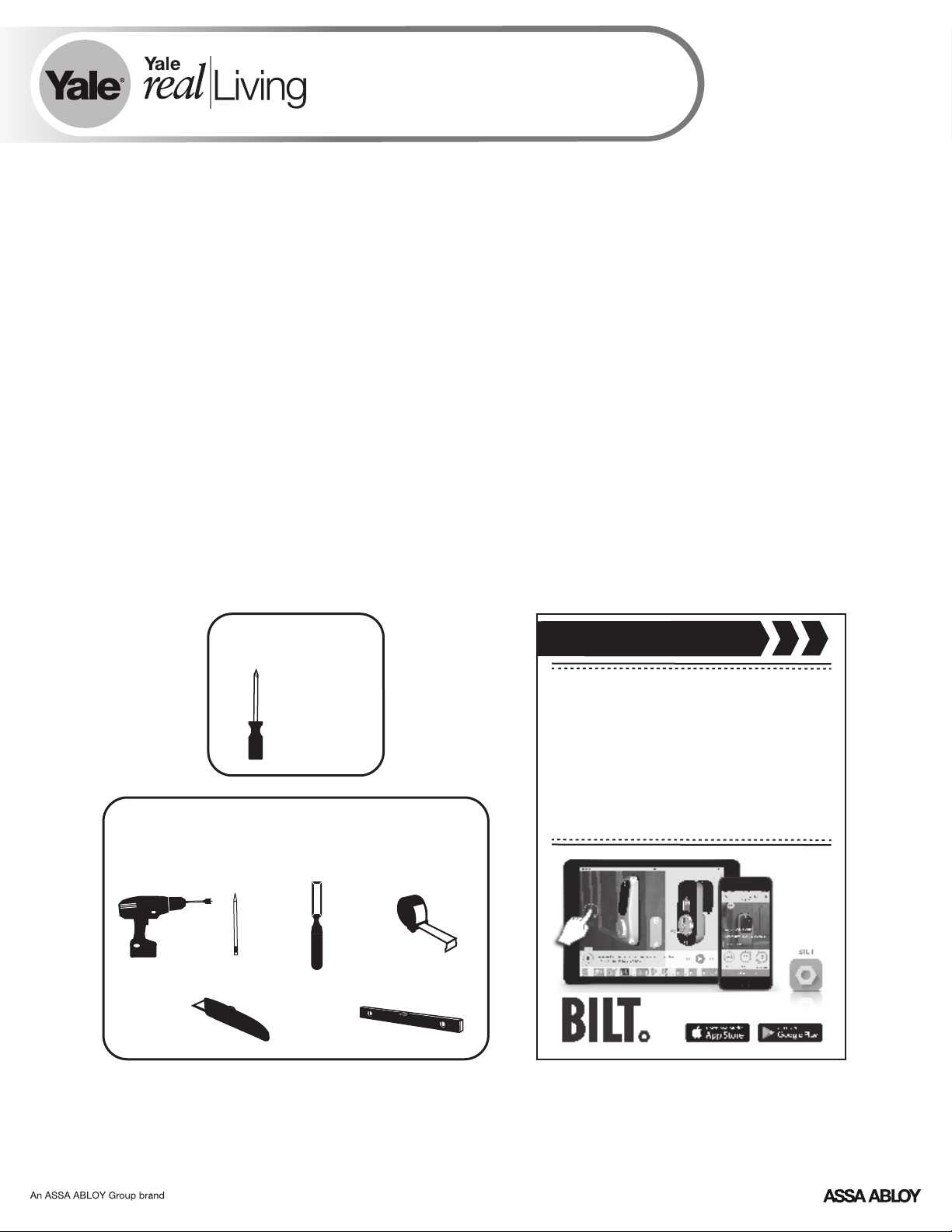
Tools Needed
Standard
Phillips Head
Screwdriver
Before you begin
DOWNLOAD
THE BILT APP
for step-by-step installation
instructions & to register
Tools necessary only for new doors
or adjusting existing door
Tape
Drill
Pencil
Wood Mortise
Chisel
Measure
your product
Utility Knife
*If purchased with Yale Smart Module or Connected by August Kit
FAILURE TO FOLLOW THESE INSTRUCTIONS COULD RESULT IN DAMAGE TO THE PRODUCT, VOIDING THE FACTORY WARRANTY AND COULD LEAD TO FAILURE OF THE PRODUCT TO PROVIDE ACCESS.
Level
1
P/N YRD256-MNL-0003 Rev E
Page 2
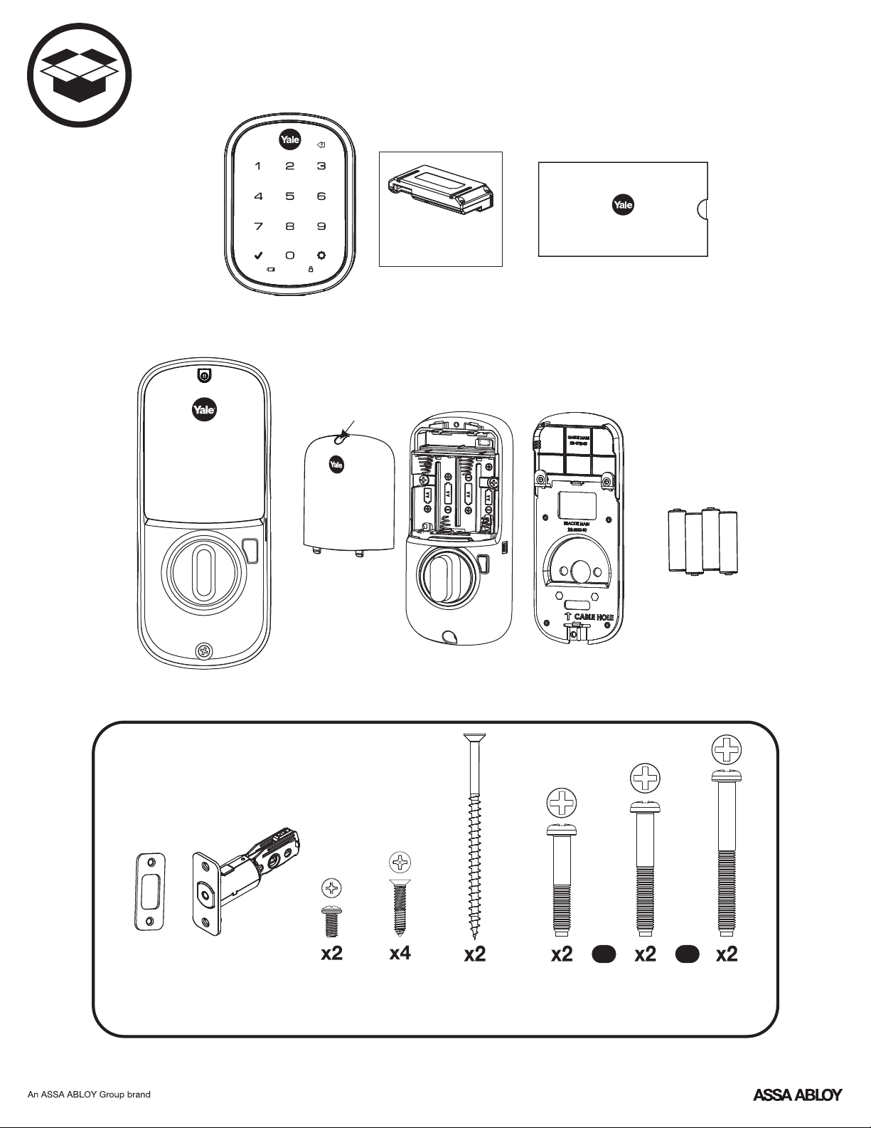
What's In The Box
Key Free Touchscreen
Keypad
Battery Cover
Smart Module
Loosen screw to
remove cover
Optional Yale
Let's Get Started
Installation Guide Envelope
(Includes this manual and
door checker with template)
4 AA Batteries
Inside Lock Assembly
(Separates into 3 components)
Mounting Hardware
The mounting hardware box includes 16 components
Adjustable
Deadbolt
Strike Plate
Inside Lock
Screws
Strike Plate
and
Deadbolt Screws
P/N YRD256-MNL-0003 Rev E
Inside Lock Mounting Plate
OR OR
Optional
Security
Strike Plate
Screws
Screw Set B
Green
for
1-3/8"
Door Thickness
2
Screw Set C
Black
Standard for
1-3/4"
Door Thickness
Screw Set D
Silver
for
2 to 2-1/4"
Door Thickness
Page 3
1
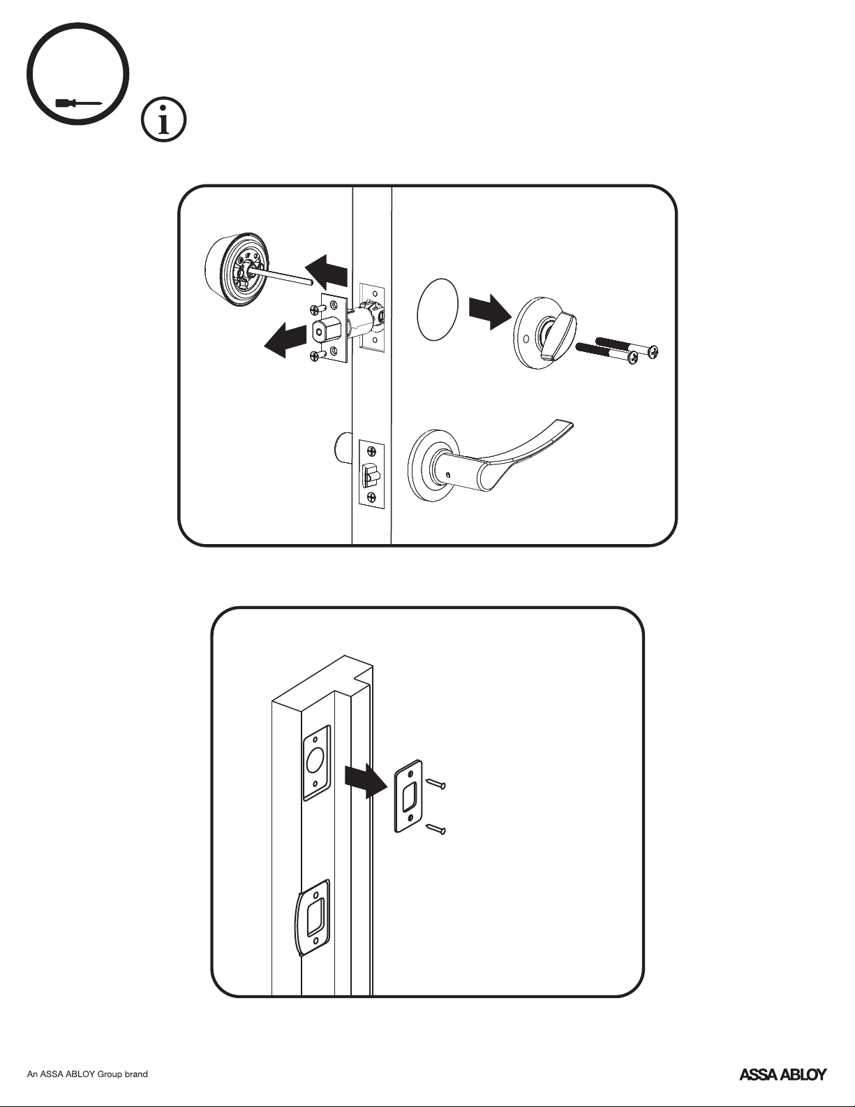
Removing Existing Door Hardware
Do not discard old lock hardware until Assure Lock SL has been successfully installed.
Frame
3
P/N YRD256-MNL-0003 Rev E
Page 4
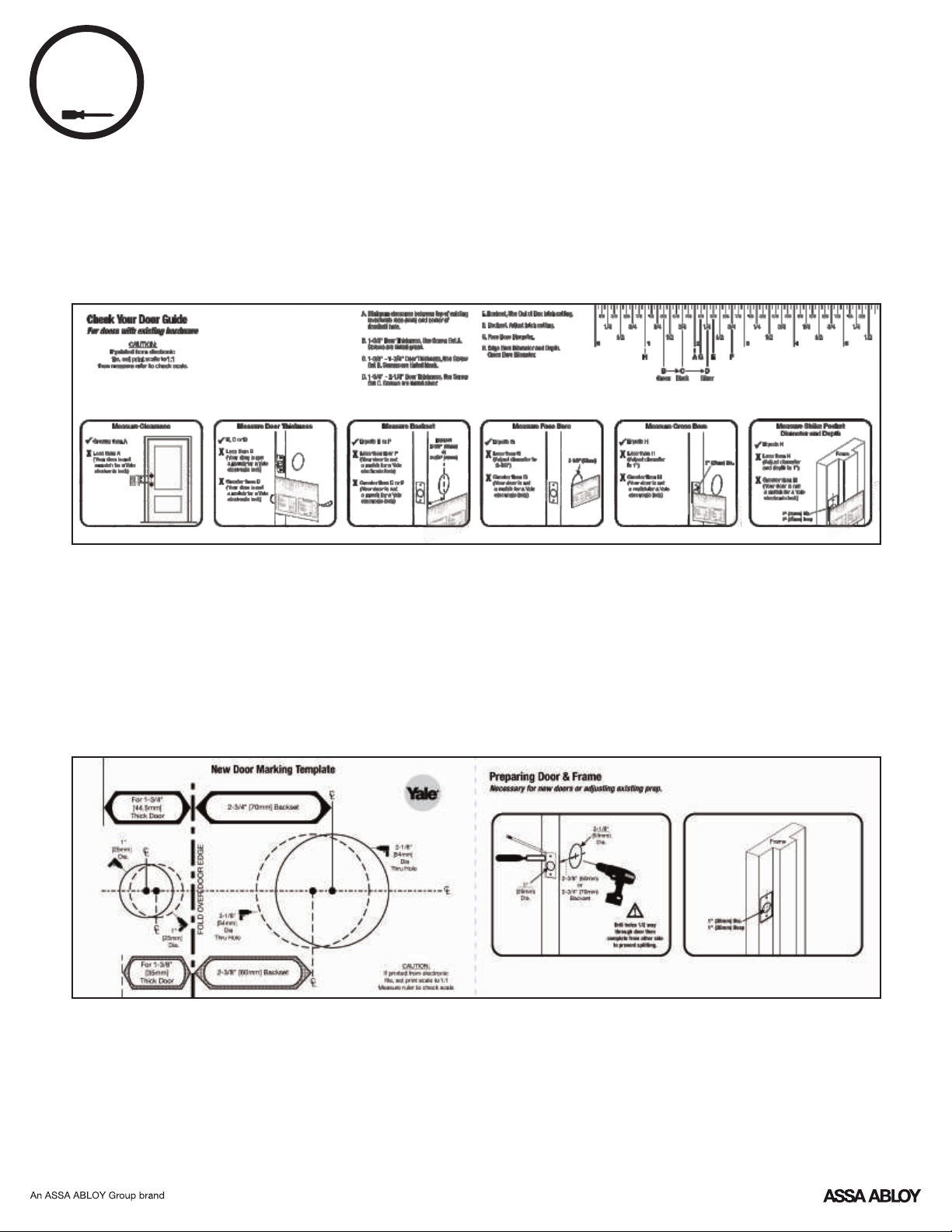
Check Door Measurements and
2
Door Checker
Use door checker from installation guide envelope to verify your door
measurements and make any needed adjustments.
Make Adjustments If Needed
New Door Marking Template
With door checker, use template from installation guide envelope to prep a new door
that has not been predrilled for hardware.
4
P/N YRD256-MNL-0003 Rev E
Page 5
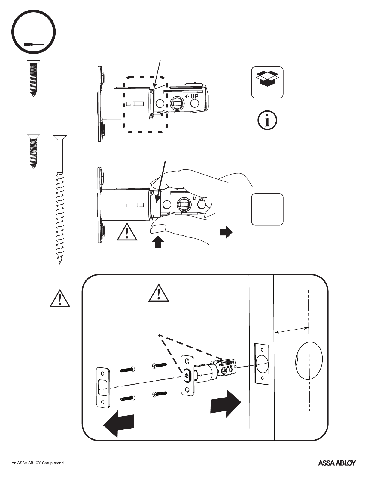
3
x2
Actual Size
x2
Actual Size
Installing Latch & Strike Plate
*2-3/8" Backset
*Deadbolt latch position is based
*2-3/4" Backset
default
on backset. Choose position
appropriate for your door.
Reference Door Checker
measurements E and F.
x2
Actual Size
Choose
standard
strike plate
screws or
security
screws.
Bolt must be
in retracted
(unlocked)
position.
Bolt must be in retracted
(unlocked) position. Note horizontal
orientation of tailpiece slot and UP
orientation of deadbolt latch.
Press
O
optional
Pull
Backset
5
P/N YRD256-MNL-0003 Rev E
Page 6
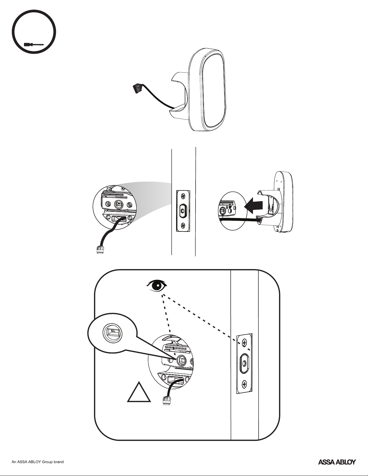
4
Installing Touchscreen Keypad
Inside of Door
Outside of Door
!
Bolt must be in retracted
(unlocked) position. Note
horizontal orientation of
tailpiece slot.
P/N YRD256-MNL-0003 Rev E
6
Page 7
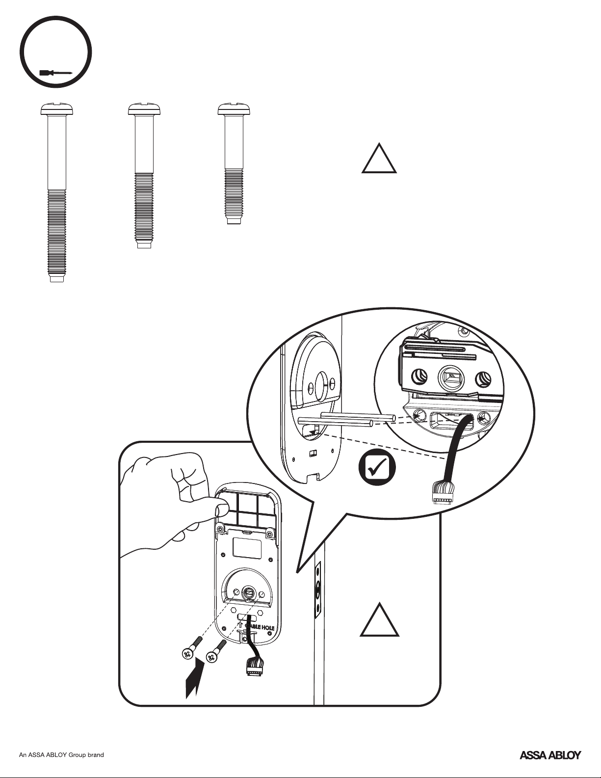
5
Installing Inside Mounting Plate
!
Choose through bolt appropriate for
your door thickness. Verify appropriate
through bolt with the door checker.
x2
x2
Actual Size
Screw Set D
Silver
for
2 to 2-1/4"
Door Thickness
x2
Actual Size
Screw Set C
Black
Standard for
1-3/4"
Door Thickness
Actual Size
Screw Set B
Green
for
1-3/8"
Door Thickness
Insert cable
through cable hole.
Make sure keypad
and mounting plate
are straight before
tightening screws.
Inside of Door
7
P/N YRD256-MNL-0003 Rev E
!
Page 8
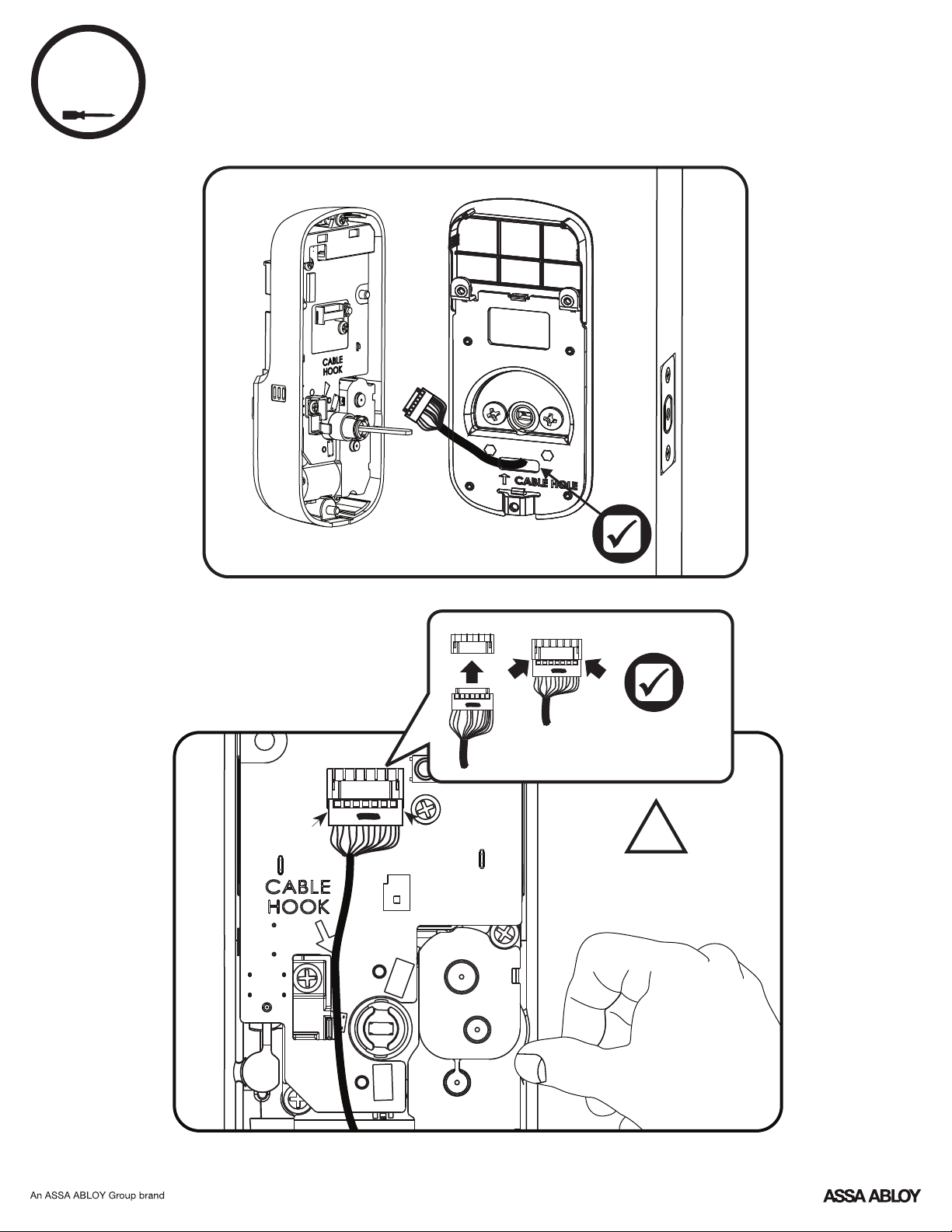
6
Attaching the Cable Assembly
Inside of Door
8
P/N YRD256-MNL-0003 Rev E
Ensure cable is
securely fastened
into adapter.
!
Use cable hooks to
ensure proper routing.
Do not pinch wire.
Page 9
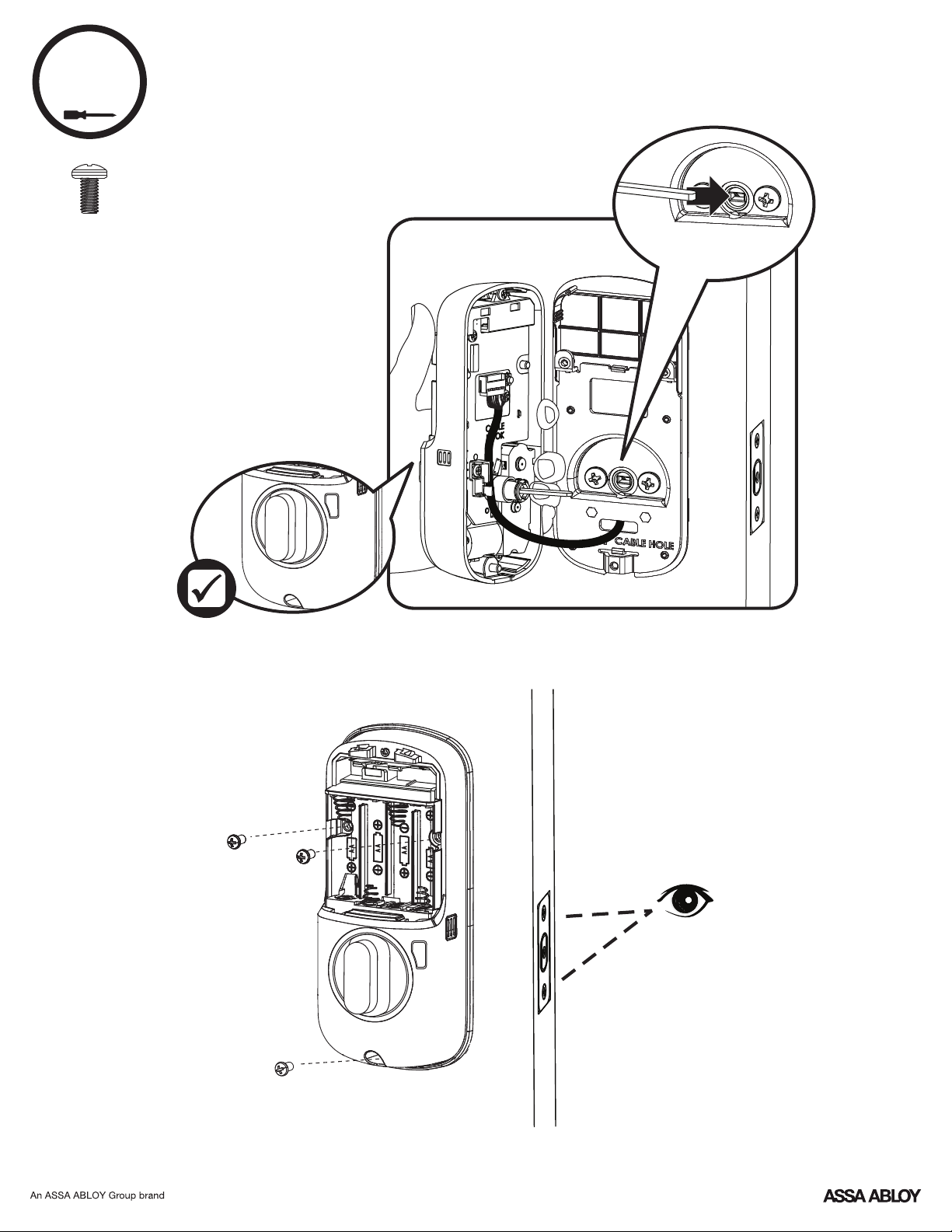
7
Installing Inside Lock
x3
Actual Size
is vertical. If the thumbturn
does not move freely, refer
Ensure thumbturn
to the hardware
troubleshooting steps.
Inside of Door
Horizontal
9
P/N YRD256-MNL-0003 Rev E
Page 10
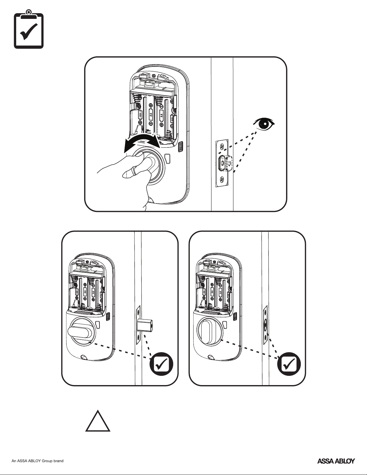
Testing Mechanical Operation
Inside of Door
If thumbturn operation fails, check the installation beginning with Step 3.
!
10
P/N YRD256-MNL-0003 Rev E
Page 11
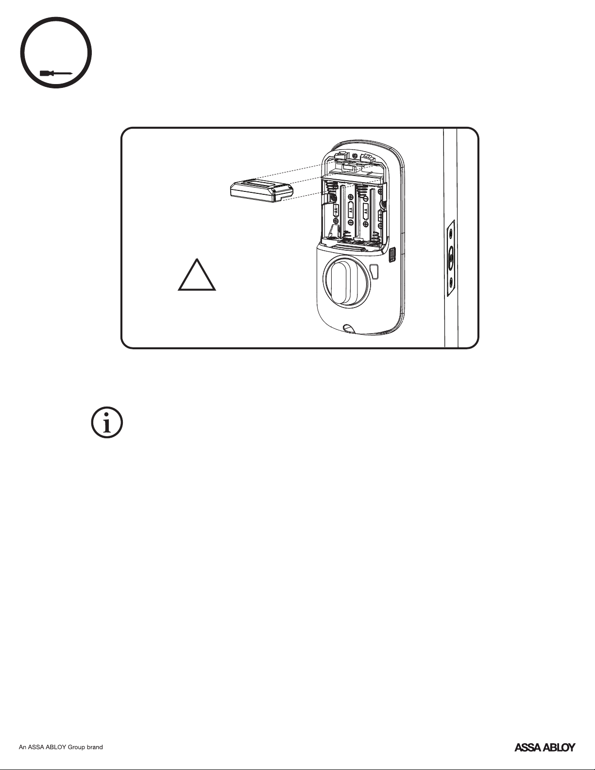
8
Installing Optional Yale Smart Module
Inside of Door
!
Batteries must not be
installed prior to inserting
and/or removing the Yale
Smart module.
For more information about Yale Smart modules and smart home features visit:
https://www.yalehome.com/en/yale/yalehome/residential/yale-smart-home-guide/
11
P/N YRD256-MNL-0003 Rev E
Page 12
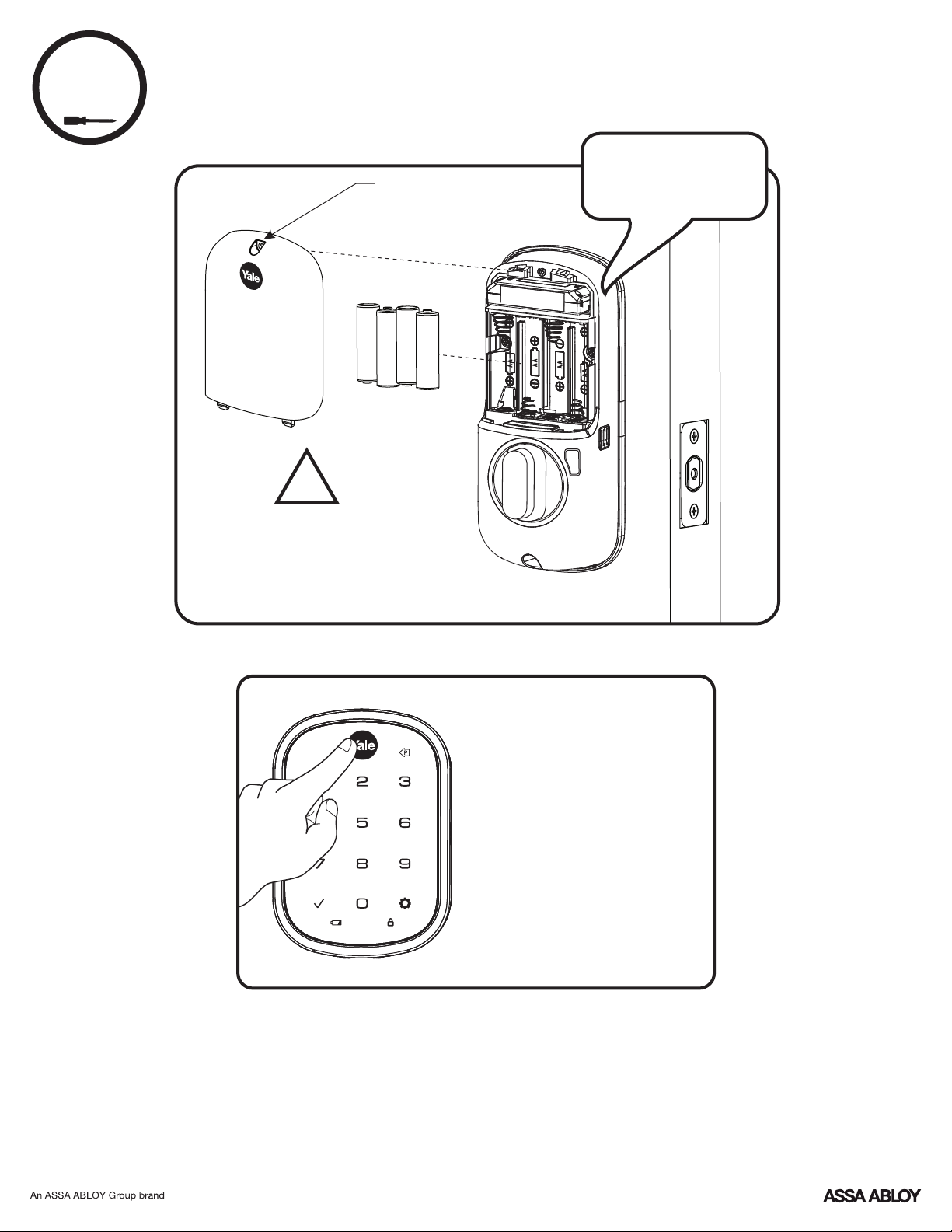
9
Installing Batteries and Cover
Tighten screw
to replace cover
!
Bolt must be in retracted
(unlocked) position before
installing batteries.
"Welcome to
Yale Real Living"
Inside of Door
Press the Yale logo to wake the lock.
You will be guided to set up your
lock by following the audio
instructions on the lock.
Additional entry codes and further
programming can be done through
the Settings Menu. Refer to page 15.
Congratulations, you've installed the Yale Assure Lock SL
® ®
Key Free Touchscreen Deadbolt ( )!YRD256
12
P/N YRD256-MNL-0003 Rev E
Page 13
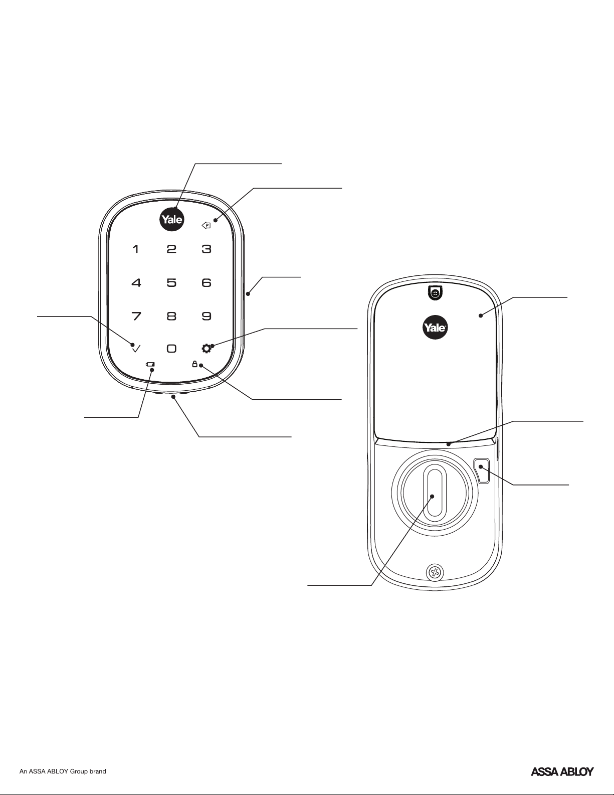
Press to enter
or unlock
Using Your Lock
Touchscreen Keypad
Press to wake keypad
or lock door
Press to return to
previous Settings Menu
Inside Lock
Speaker
Battery Cover
Enter Master Entry Code
and press to access
Settings Menu
Low Battery
Indicator
All Code Lockout Mode
Indicator
Battery Back-up
Hold a 9V battery to the
terminals in case of dead
lock batteries
Inside Notification
Light
Privacy Button
Thumbturn for
manual locking
and unlocking
13
P/N YRD256-MNL-0003 Rev E
Page 14
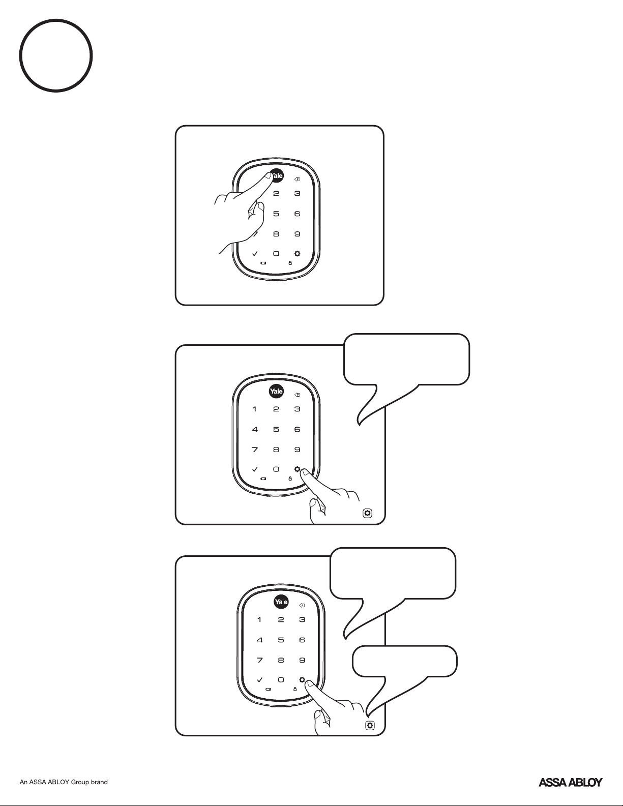
1
Creating Master Entry Code
The master entry code is used to change the lock settings.
A security best practice is to set your master code with 6 or more digits and create a separate code
that is used daily to lock and unlock the door.
"Register Master
Code. Press the gear
key to continue."
Enter 4-8
digit Master
Entry Code
Press
"Enter a 4 to 8 digit
PIN code followed by
the gear key."
"Registered"
Press
14
P/N YRD256-MNL-0003 Rev E
Page 15
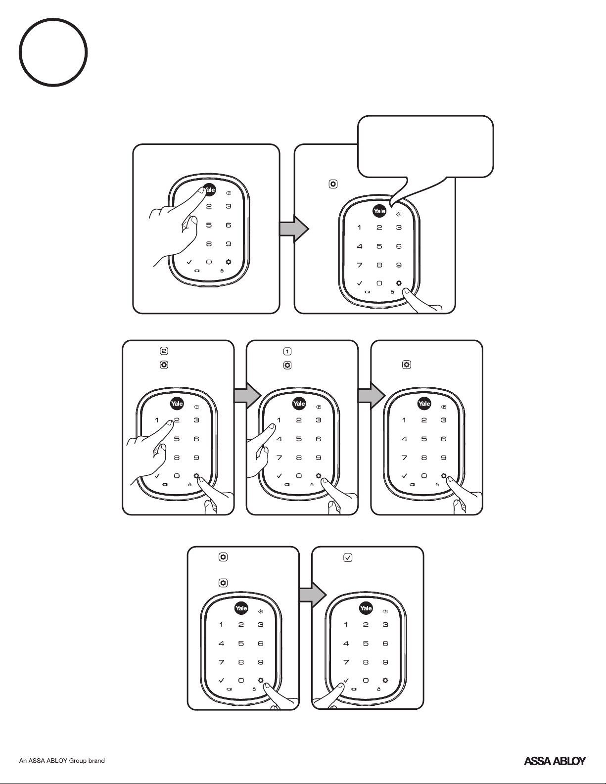
2
Creating Entry Codes
Master Entry Code must be created first.
*Max user codes = 250 with Smart Module; 25 without.
Enter Master
Entry Code
Press
"Menu mode, press the
gear key to continue."
Press
Press
Press
Press
Adding more *User Codes:
Press
Enter 4-8 digit entry code
Press
Enter 4-8 digit entry code
Press
(code flashes)
To end programming:
Press
15
P/N YRD256-MNL-0003 Rev E
Page 16
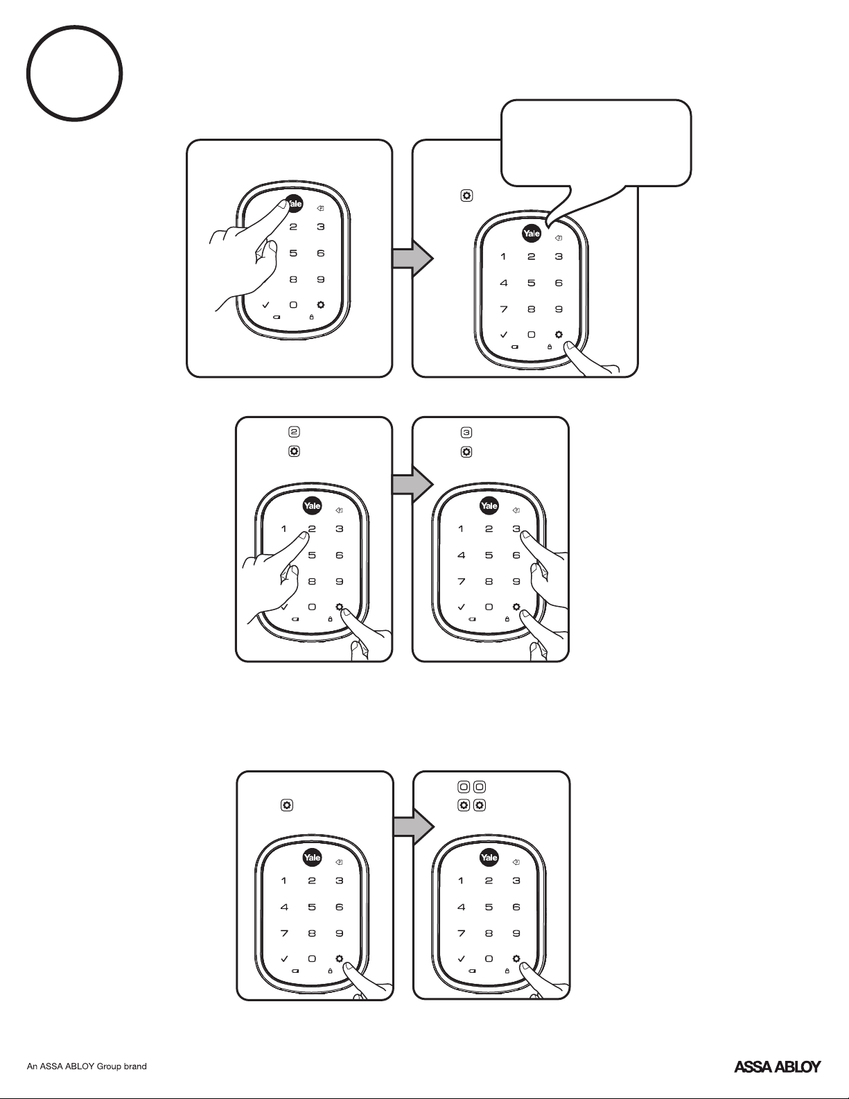
3
Deleting Entry Codes
Enter Master
Entry Code
Press
"Menu Mode,
enter number,
press the gear key
to continue."
Press
Press
Deleting one entry code:
To delete one entry code,
you must enter the entry
code you wish to delete.
Enter 4-8 digit entry code
Press
Press
Press
To delete all entry codes
(Does not delete Master Entry Code):
Enter
Press
16
P/N YRD256-MNL-0003 Rev E
Page 17
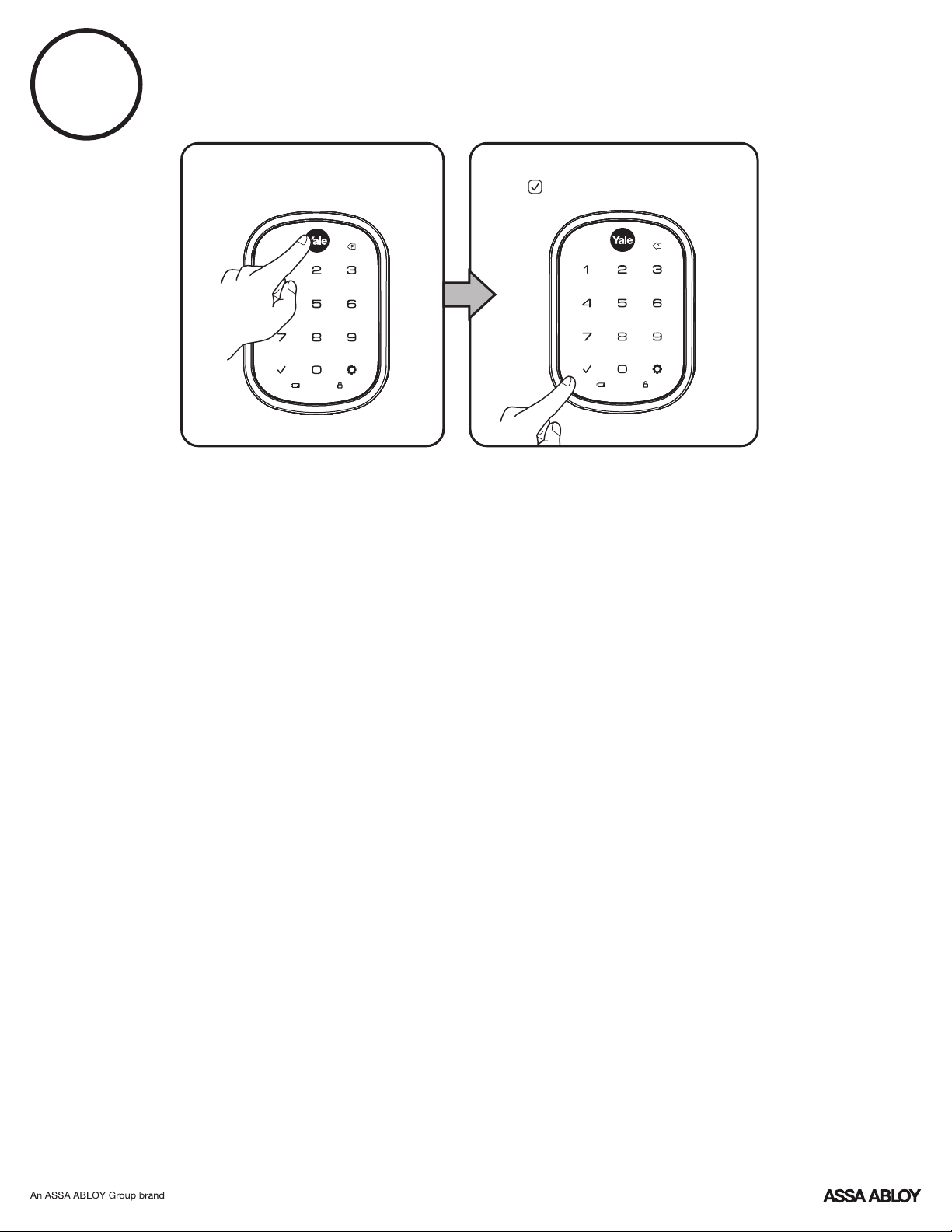
4
Unlocking Door with Entry Codes
Enter Entry Code
Press
17
P/N YRD256-MNL-0003 Rev E
Page 18
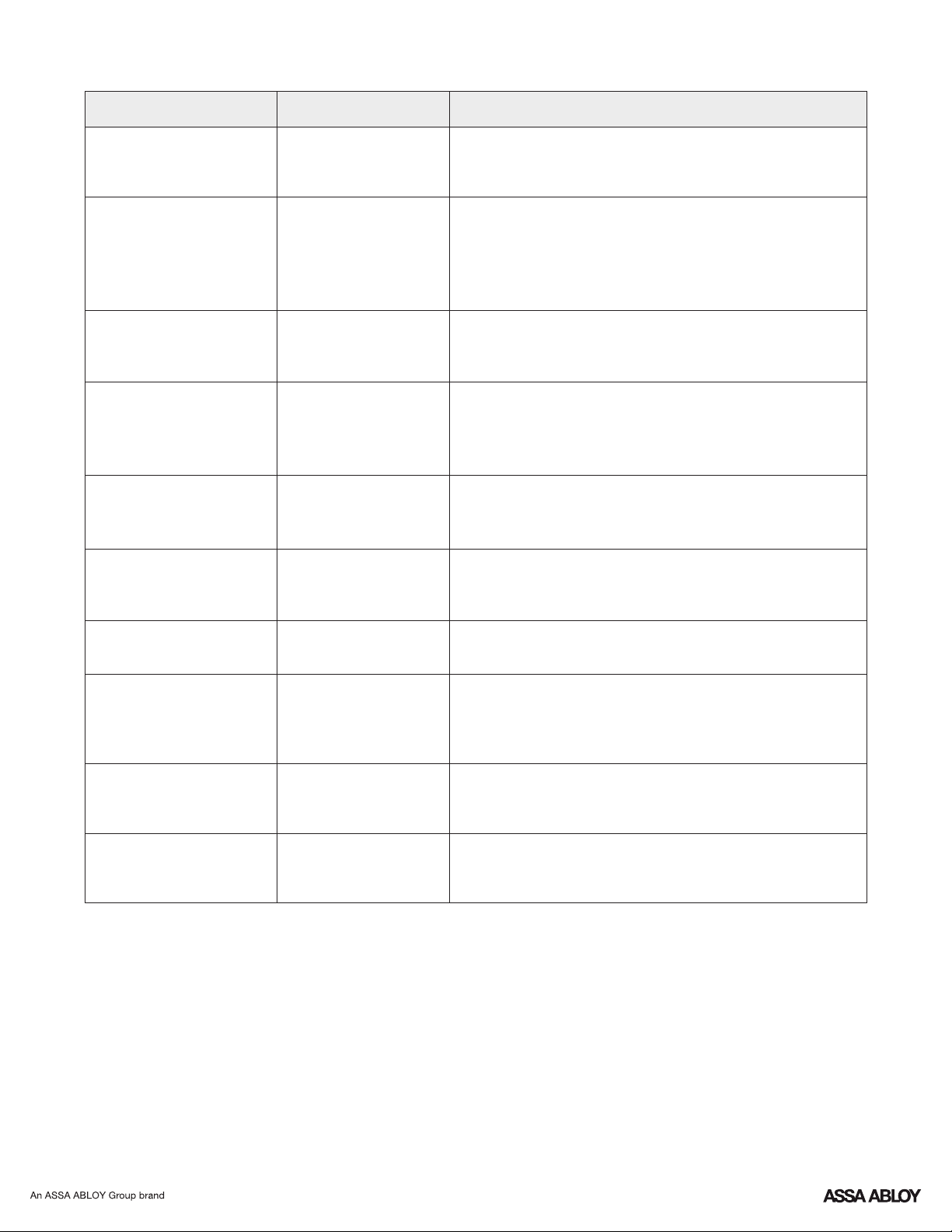
Setting Definitions
Settings Default Setting
Master Entry Code
Creation required*
Auto Re-lock
Inside Indicator Light
One Touch Locking
Privacy Button
Disabled
Disabled (Off)
Enabled
Disabled
Definition
The Master Entry Code is used for programming and for feature
settings. It must be created prior to programming the lock. The
Master code will also operate (unlock/lock) the lock.
After a successful code entry or manual unlock with the key, the
lock will automatically re-lock after each unlock in an effort to keep
your home secure. This feature is optional, and can be turned off.
In the ON mode, the lock will automatically re-lock after thirty (30)
seconds.
Located on the inside lock. Shows active status (Locked) of lock
and can be enabled or disabled in the Advanced Lock Settings
(Main Menu selection #3).
When the latch is retracted, activating the keypad will extend the
latch (during Auto Re-lock duration or when Auto Re-lock is
disabled). When One-Touch Re-lock is not in use (disabled), any
valid PIN code will re-lock the lock.
Privacy mode is disabled by default. Enable Privacy mode by
pressing the privacy button for 4 seconds to put the lock in donot-disturb mode (all pin codes are disabled).
The volume setting for entry code verification is set to Low (2) by
Volume
Enabled (Low)
Language English
All Code Lockout Mode
Disabled
Wrong Code Entry Limit
Shutdown Time 60 Seconds
5 Times
default; otherwise it can be set to High (1) or Silent (3) for quiet
areas.
Choosing English (1), Spanish (2) or French (3) becomes the
(default) setting for the lock's voice prompts.
This feature is enabled by the Master Entry Code. When enabled, it
restricts all user (except Master) Entry Code access. When
attempting to enter a code while the lock is in All Code Lockout
mode, the RED locked padlock will appear on the screen.
After five (5) unsuccessful attempts at entering a valid entry code,
the lock will shut down and not allow operation for sixty (60)
seconds.
The Lock will shutdown (flashing RED) for sixty (60) seconds and
not allow operation after the wrong code entry limit (5 attempts)
has been met.
*The Master Entry Code must be created prior to any other programming of the lock.
18
P/N YRD256-MNL-0003 Rev E
Page 19
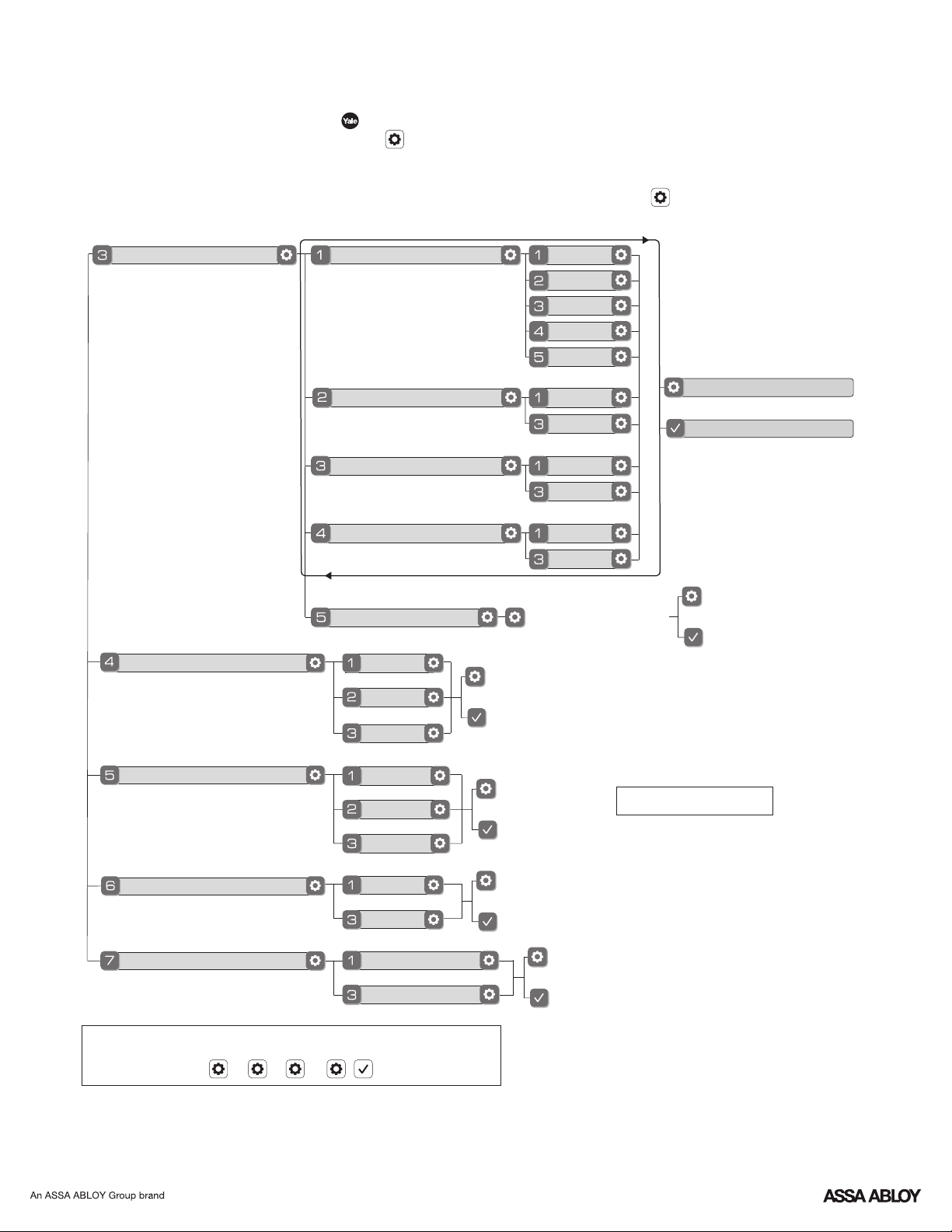
Customizing Lock Through Settings Menu
*Master Entry Code Required
1. Press Yale logo to wake up lock .
2. Enter Master Entry Code* followed by icon.
Lock Response: "Welcome to the Settings Menu. Press each number to hear available settings
and then press the settings icon to enter."
3. Enter digit corresponding to the function to be performed followed by the icon.
Follow the voice commands.
Advanced Lock Settings
Volume Setting
Auto Re-lock
Inside Indicator Light
One Touch Locking
Privacy Button Setting
Handing the Lock
High
Low
OR
Disable
30 sec
60 sec
2 min
3 min
Enable
Disable
Enable
Disable
Enable
Disable
Preforms automatic
handing of the lock
Remain in Settings Menu
OR
Exit Settings Menu
OR
Silent
Language Setting Mode
English
Spanish
OR
French
All Code Lockout Mode
Enable
OR
Disable
**Network Module Setting
Join the Network
OR
Exit the Network
Here is an example of how to set Auto Lock to 30 seconds:
Master Entry Code , 3 , 1 , 2 ,
*The Master Entry Code must be created prior to any other programming of the lock.
**Network Module Setting function appears only with Yale Smart module installed.
19
P/N YRD256-MNL-0003 Rev E
Default settings in bold.
Page 20
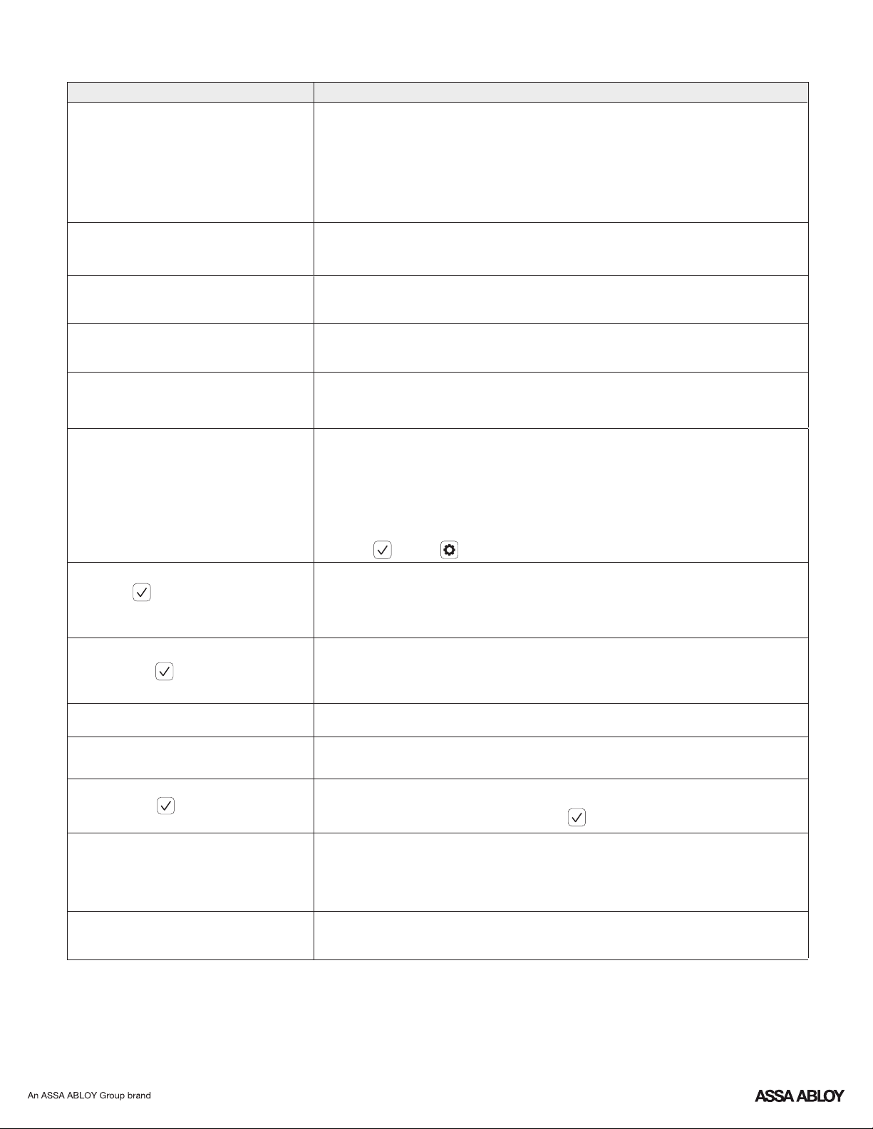
Troubleshooting
Symptom
Lock does not respond –
door is open and accessible.
Lock does not respond –
door is locked and inaccessible.
Lock is on for a while then shows no
reaction. Lights dim.
Lock chimes to indicate code
acceptance, but door will not open.
Lock operates to allow access, but
will not automatically re-lock.
Entry codes will not register.
Upon entering an entry code and
pressing key, the lock displays
"invalid code" error or lock times out
without responding.
Suggested Action
Yale keypad becomes active when the Yale logo is pressed.
•
Verify contact with the logo.
If keypad numbers are visible, check to see if they respond when pressed.
•
Check batteries are installed and oriented correctly (polarity) in battery case.
•
Check batteries are in good condition; replace batteries* if batteries are dead.
•
Check to see if keypad cable is fully connected and is not pinched.
•
Batteries may not have enough power. Replace batteries*.
•
Apply a 9V battery to terminals below the keypad for backup power option.
•
Batteries do not have enough power. Replace batteries*.
•
Check the door gaps for any foreign objects between door and frame.
•
Check that the cable is firmly connected to the inside lock.
•
Check to see if Auto Re-lock is enabled.
•
Disable Auto Re-lock to lock the door (manually).
•
If low battery indicator is lit, change batteries*.
•
Entry codes must consist of 4 to 8 digits.
•
The same entry code cannot be used for multiple users.
•
Management of entry codes is set by the authority of the Master Code, which is
•
set first. Contact the Master user.
Entry codes must be entered within 5 seconds (while keypad is active) or
•
process will have to be restarted.
Check or gear cannot be used as part of the entry code.
•
Verify entered code is a valid, previously programmed, 4 to 8 digit code.
•
All Code Lockout Mode is enabled. Only the Master Entry Code can
•
enable/disable All Code Lockout Mode. Contact the Master user.
Upon entering an entry code and
pressing the key, red padlock icon
appears and there are different tones.
Lock operates, but makes no sound.
Lock responds "Low Battery"
Upon entering an entry code and
pressing the key, lock responds
"Wrong number of digits".
Lock shows an X on keypad after
entering a code.
Check to see if the lock is set to All Code Lockout Mode. Setting/managing All
•
Code Lockout Mode is done through Master Entry Code only.
Contact Master user.
Check to see if Volume is set to Silent (see Feature #4).
•
This is the alert to replace the batteries. Replace all four (4) batteries* with new
•
AA Alkaline batteries.
•
The digits entered were incorrect or incomplete. Re-enter
the correct code followed by the check key.
Bolt failed to fully retract.
•
Refer to the "Hardware Troubleshooting" steps on page 21.
Entry code has not been scheduled for use at time of day it is tried.
•
Try entry code again during its scheduled time.
Deadbolt does not extend when
locking the door with keypad.
* When batteries are replaced, Smart Module locks have a real time clock that will be set through the User Interface (UI);
it is recommended to verify correct date and time particularly those locks operating under Daylight Saving Time (DST).
Lock was not handed properly. Rehand lock through settings menu.
•
20
P/N YRD256-MNL-0003 Rev E
Page 21
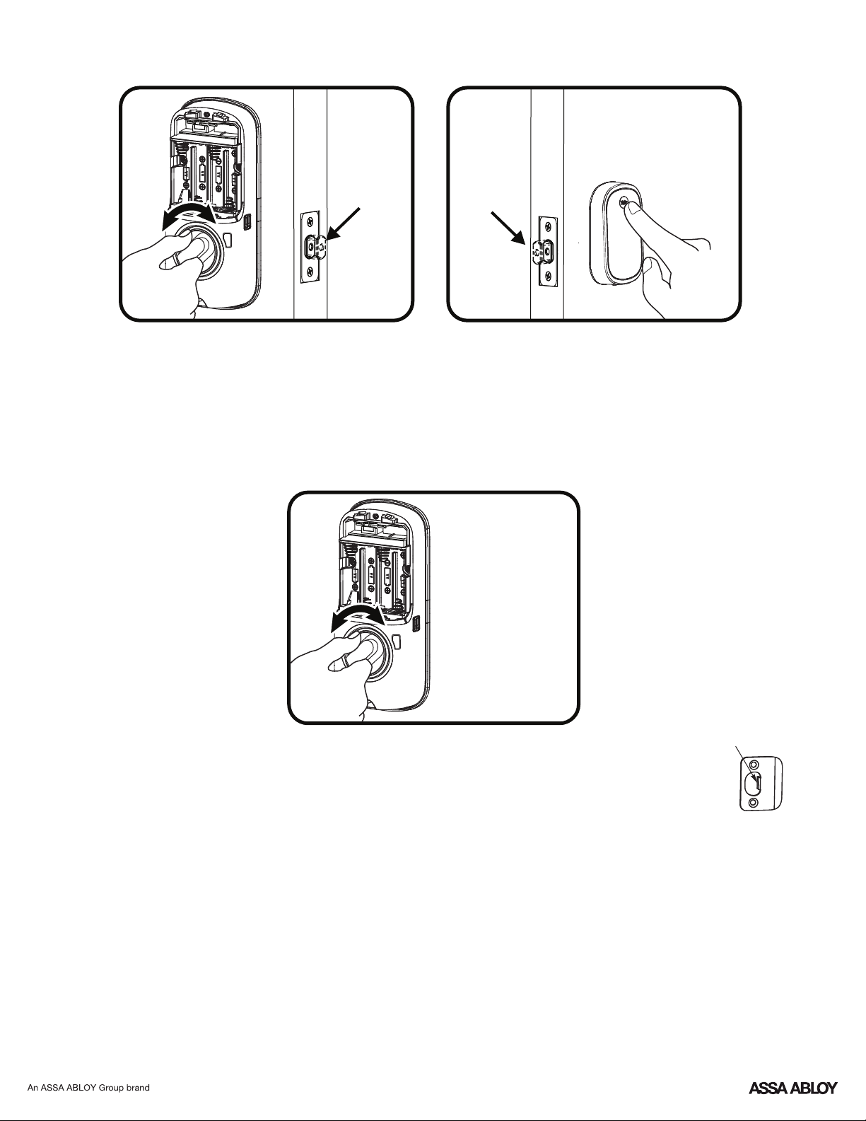
Hardware Troubleshooting
Thumbturn
Door Open
If deadbolt does not extend or retract easily when testing thumbturn and keypad operation,
revisit inside and keypad installation steps. It is important that the bolt be in the retracted
position during lock installations and that installation procedure is followed carefully.
Helpful Tip:
Ensuring smooth deadbolt operation can enhance your battery life.
Keypad
Door Open
Thumbturn
Door Closed
If you feel resistance, ensure deadbolt strike plate
aligns with deadbolt. If deadbolt strike plate is out of
alignment, please attempt to adjust
knob/lever/handleset strike using steps below. The
knob/lever/handleset latch engagement into the strike is
the main component used for door alignment.
If deadbolt does not fully extend, consider increasing
depth of deadbolt strike pocket in frame.
To adjust Knob/Lever/Handleset strike plate:
1. Remove plate from door frame with a manual
screwdriver. (Using an electric driver may strip screw
heads or enlarge screw holes.)
Test with door
closed using
thumbturn.
2. Locate strike plate tab.
Bend the tab towards surface of
strike. Note: a small change may be
all that is required
3. Reinstall strike plate using a manual screw driver
and test again.
4. If door cannot be adjusted sufficiently with strike
tab, both knob/lever/handleset latch and deadbolt
latch could require adjustment – we suggest you
contact a local locksmith for assistance.
For help with misalignments, watch our door
alignment video:
https://www.yalehome.com/en/yale/yalehome/support/
yrl-electronic-lock-faqs/electronic-lock-installation/
Tab
21
P/N YRD256-MNL-0003 Rev E
Page 22
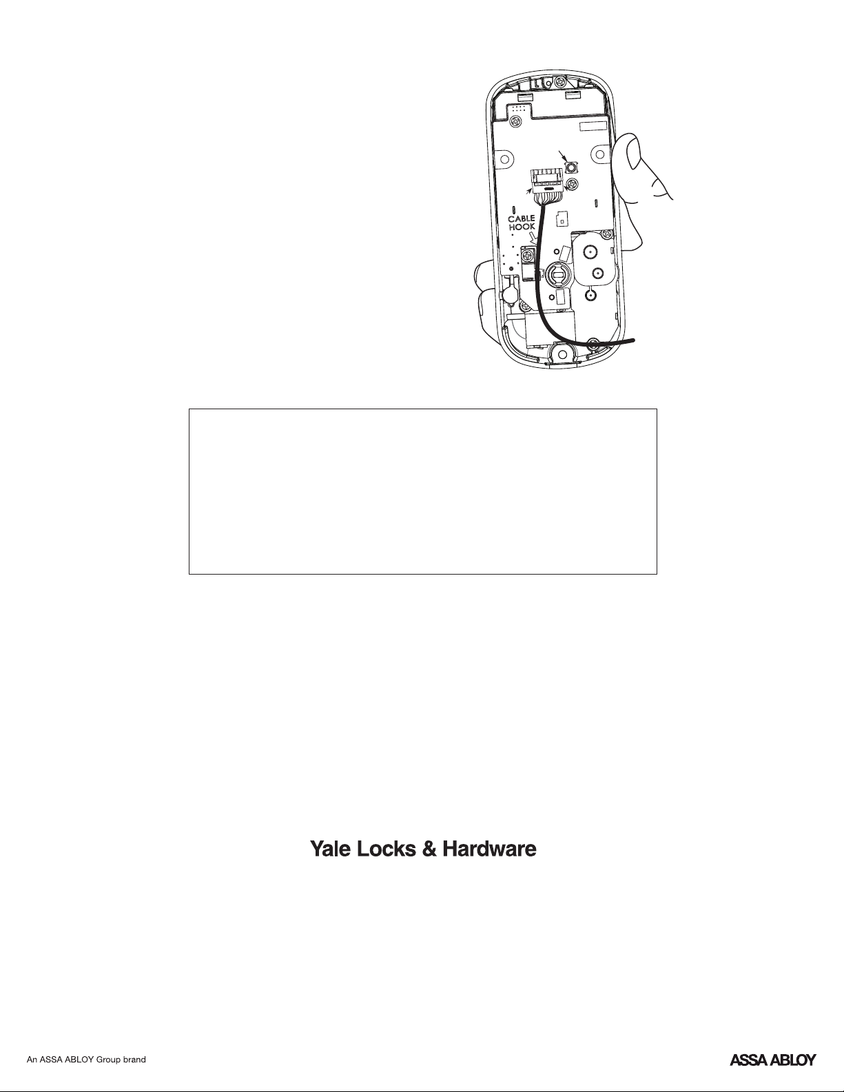
Resetting Lock to Factory Default
When lock is reset to factory defaults all user codes
(including the Master Entry code*) are deleted and all
programming features are reset to original default settings
(see below).
1. Remove the battery cover and batteries.
2. Remove the interior side of the lock to access the
reset button.
3. The reset button (see image at right) is located beside
the cable adapter.
4. While pressing the reset button (minimum of 3 seconds)
reinstall batteries. Release reset button.
5. Replace battery cover.
Upon reset, Master Entry Code creation is the only option
available and must be performed prior to any other
programming of the lock.
Reset
Button
Interior Lock
NOTE TO INSTALLER AND CONSUMER
While Yale has included several features to prevent lockout
®
(9-Volt battery jumper, low battery warnings), it is still possible
for a lockout situation to occur. Because this product does not
have a mechanical override (a key), Yale recommends to use
®
this product in an environment where there are additional
entry points into the dwelling.
FCC:
Class B Equipment
This equipment has been tested and found to comply with the limits for a Class B digital
device, pursuant to Part 15 of the FCC Rules. These limits are designed to provide reasonable protection against harmful interference in a residential installation. This
equipment generates, uses, and can radiate radio frequency energy and, if not installed and used in accordance with the instructions, may cause harmful interference to
radio communications. However, there is no guarantee that interference will not occur in a particular installation. If this equipment does cause harmful Interference to radio
or television reception, which can be determined by turning the equipment off and on, the user is encouraged to try to correct the interference by one or more of the
following measures:
Ÿ Reorient or relocate the receiving antenna.
Ÿ Increase the separation between the equipment and receiver.
Ÿ Connect the equipment into an outlet on a circuit different from that to which the receiver is connected.
Ÿ Consult the dealer or an experienced radio/TV technician for help.
Warning: Changes or modifications to this device, not expressly approved by ASSA ABLOY Residential Group could void the user's authority to operate the equipment.
Industry Canada:
This Class A digital apparatus meets all requirements of the Canadian Interference Causing Equipment Regulations.
Cet appareillage numérique de la classe A répond à toutes les exigences de l'interférence canadienne causant des règlements d'équipement.
Product Support Tel 1-855-213-5841 • www.yalehome.com
Yale®, Yale Real Living® and Assure Lock® are registered trademarks of ASSA ABLOY Residential Group. Other
products' brand names may be trademarks or registered trademarks of their respective owners and are mentioned for
reference purposes only. © Copyright 2018, 2019. All rights reserved. Reproduction in whole or in part without the
express written permission of ASSA ABLOY Residential Group is prohibited.
22
P/N YRD256-MNL-0003 Rev E
Page 23
® ®
®
Yale Z-Wave Plus Smart Module
Installation Guide
Please use this procedure only when network primary controller is missing
or otherwise inoperable.
Adding a Yale Z-Wave Plus Smart Module to your Assure Lock & Z-Wave System
®
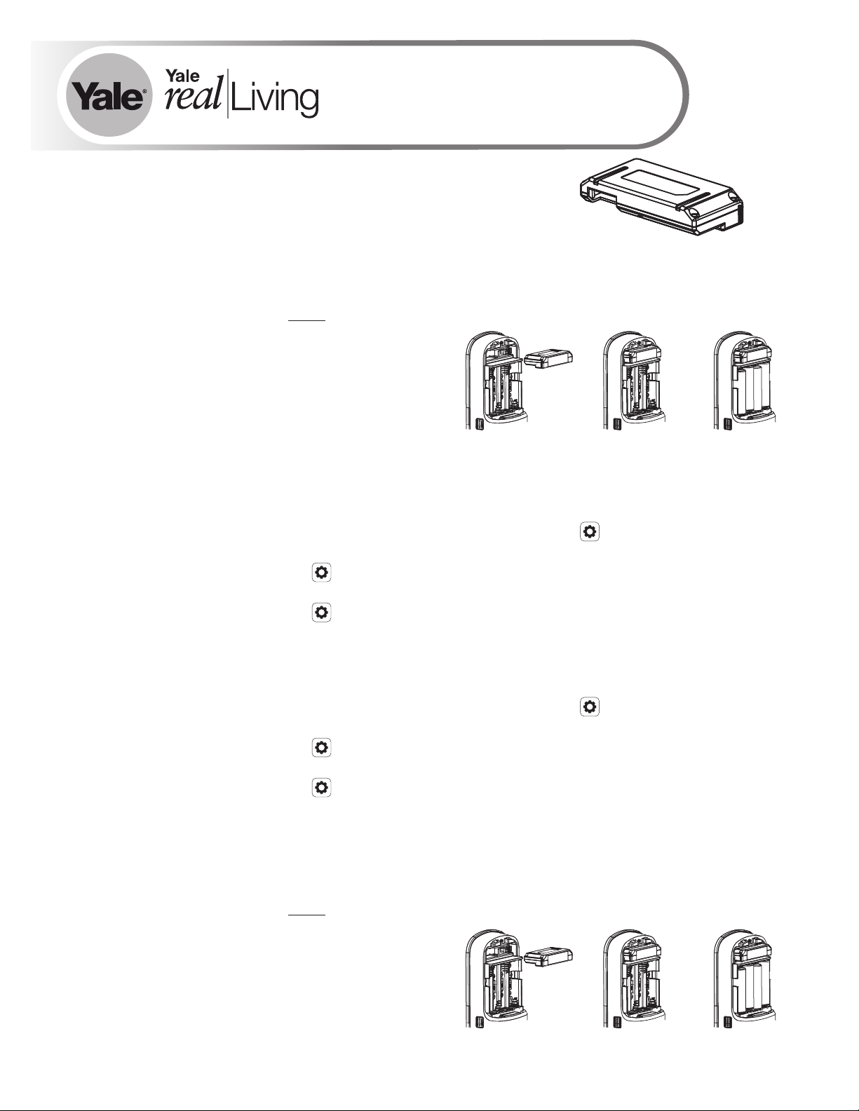
1. Install the Yale Smart Module into the slot above the battery compartment
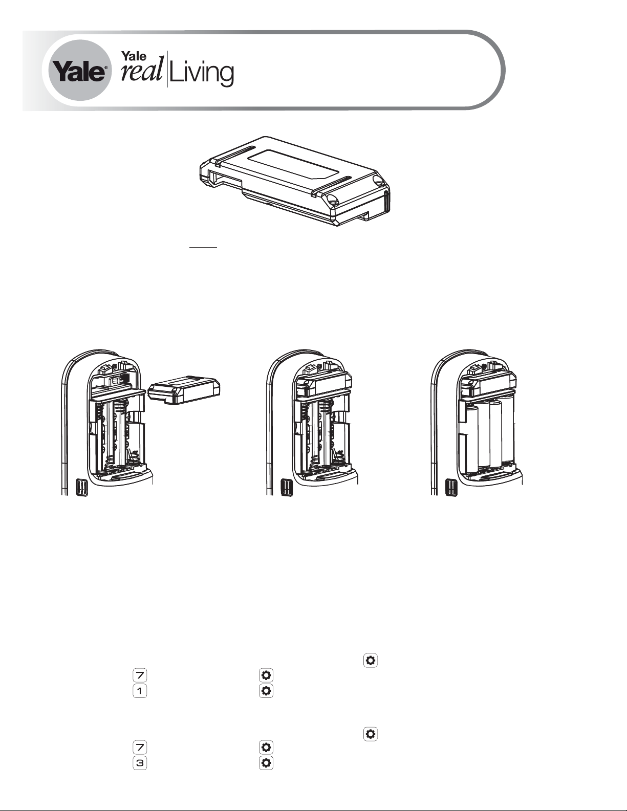
IMPORTANT: The batteries must be removed before removing the Yale Smart Module:
• Remove battery cover
• Remove batteries
• Insert or remove Yale Smart Module
• Reinstall batteries
• Reinstall battery cover
2. Open the Z-Wave system's smart home or alarm app on your smartphone or tablet
3. Follow the in-app instructions for adding a new device
4. On your lock keypad, enter your master entry code followed by the icon
5. Press the 7 key followed by the icon
6. Press the 1 key followed by the icon
Removing a Yale Z-Wave Plus Smart Module from your Assure Lock & Z-Wave System
®
1. On your lock keypad, enter your master entry code followed by the icon
2. Press the 7 key followed by the icon
3. Press the 3 key followed by the icon
4. Open the Z-Wave system's smart home or alarm app and follow the instructions for
removing a device
5. Remove the Yale Smart Module from the slot above the battery compartment
IMPORTANT: The batteries must be removed before removing the Yale Smart Module:
• Remove battery cover
• Remove batteries
• Insert or remove Yale Smart Module
• Reinstall batteries
• Reinstall battery cover
6. If you're adding a new Yale Smart Module, follow the instructions included with it
P/N AYR202-ZW-INSTAL-FUL Rev E
Page 24
Warning: Changes or modifications to this device, not expressly approved by ASSA ABLOY
Residential Group could void the user's authority to operate the equipment.
!
This device is a security enabled Z-Wave Plus product that is able to use encrypted Z-Wave Plus messages to
communicate to other security enabled Z-Wave Plus products. This device must be used in conjunction with a Security
Enabled Z-Wave Controller in order to fully utilize all implemented functions. This product can be operated in any ZWave network with other Z-Wave certified devices from other manufacturers. All non-battery operated nodes within the
network will act as repeaters regardless of vendor to increase reliability of the network.
FCC:
Contain FCC ID: U4A-YRHCPZW0FM
Model: YRMZW2-US
This equipment has been tested and found to comply with
the limits for a Class B digital device, pursuant to Part 15 of
the FCC Rules. These limits are designed to provide
reasonable protection against harmful interference in a
residential installation. This equipment generates, uses, and
can radiate radio frequency energy and, if not installed and
used in accordance with the instructions, may cause harmful
interference to radio communications. However, there is no
guarantee that interference will not occur in a particular
installation. If this equipment does cause harmful
Interference to radio or television reception, which can be
determined by turning the equipment off and on, the user is
encouraged to try to correct the interference by one or more
of the following measures:
Ÿ Reorient or relocate the receiving antenna.
Ÿ Increase the separation between the equipment and
receiver.
Ÿ Connect the equipment into an outlet on a circuit
different from that to which the receiver is connected.
Ÿ Consult the dealer or an experienced radio/TV technician
for help.
THIS DEVICE COMPLIES WITH PART 15 OF THE FCC RULES.
OPERATION IS SUBJECT TO THE FOLLOWING TWO
CONDITIONS.
(1) THIS DEVICE MAY NOT CAUSE HARMFUL INTERFERENCE,
AND (2) THIS DEVICE MUST ACCEPT ANY INTERFERENCE
RECEIVED, INCLUDING INTERFERENCE THAT MAY CAUSE
UNDESIRED OPERATION.
Industry Canada:
Contain IC: 6982A-YRHCPZW0FM
Model: YRMZW2-US
Section 7.1.2 of RSS-GEN Under Industry Canada
regulations, this radio transmitter may only operate using an
antenna of a type and maximum (or lesser) gain approved for
the transmitter by Industry Canada. To reduce potential radio
interference to other users, the antenna type and its gain
should be so chosen that the equivalent isotropically radiated
power (e.i.r.p.) is not more than that necessary for
successful communication.
En vertu des règlements d'Industrie Canada, cet émetteur
radio ne peut fonctionner avec une antenne d'un type et un
maximum (ou moins) approuvés pour gagner de l'émetteur
par Industrie Canada. Pour réduire le risque d'interférence
aux autres utilisateurs, le type d'antenne et son gain doivent
être choisies de façon que la puissance isotrope rayonnée
équivalente (PIRE) ne dépasse pas ce qui est nécessaire pour
une communication réussie.
Section 7.1.3 of RSS-GEN This Device complies with
Industry Canada License-exempt RSS standard(s). Operation
is subject to the following two conditions: 1) this device may
not cause interference, and 2) this device must accept any
interference, including interference that may cause
undesired operation of the device.
Cet appareil est conforme avec Industrie Canada RSS
standard exemptes de licence(s). Son fonctionnement est
soumis aux deux conditions suivantes: 1) ce dispositif ne
peut causer des interférences, et 2) cet appareil doit
accepter toute interférence, y compris les interférences qui
peuvent causer un mauvais fonctionnement du dispositif.
This radio transmitter 6982A-YRHCPZW0FM has been
approved by Industry Canada to operate with the antenna
types listed below with the maximum permissible gain
indicated. Antenna types not included in this list, having a
gain greater than the maximum gain indicated for that type,
are strictly prohibited for use with this device.
Le présent émetteur radio 6982A-YRHCPZW0FM a été
approuvé par Industrie Canada pour fonctionner avec les
types d'antenne énumérés ci-dessous et ayant un gain
admissible maximal. Les types d'antenne non inclus dans
cette liste, et dont le gain est supérieur au gain maximal
indiqué, sont strictement interdits pour l'exploitation de
l'émetteur.
CAN ICES-3B/NMB-3B
24/7 Tech Support : 1-855-492-0505 • www.yalehome.com
Yale® is a registered trademark of ASSA ABLOY Residential Group. Other products' brand names may
be trademarks or registered trademarks of their respective owners and are mentioned for reference
purposes only. © Copyright 2019. All rights reserved. Reproduction in whole or in part without the
express written permission of ASSA ABLOY Residential Group is prohibited.
Page 25
®®
®
Yale ZigBee Module
Installation and Programming Instructions
Installing the ZigBee Module
®
IMPORTANT: the batteries be removed priormust
to removing and/or inserting the network module:
• Remove battery cover.
• Remove batteries.
• Remove and/or insert network module.
• Reinstall batteries.
• Replace cover.
Enrolling/Unenrolling the Network Module:
This device is a security enabled ZigBee product that is able to use encrypted ZigBee
messages to communicate to other security enabled ZigBee products. This device must be
used in conjunction with a Security Enabled ZigBee Controller in order to fully utilize all
implemented functions. This product can be operated in any ZigBee network with other
ZigBee certified devices from other manufacturers. All non-battery operated nodes within the
network will act as repeaters regardless of vendor to increase reliability of the network.
To Enroll the Module (Inclusion Mode):
• Enter the 4-8 digit Master code followed by the key.PIN
• Press the key followed by the key.
• Press the key followed by the key.
To Unenroll the Module (Exclusion Mode):
• Enter the 4-8 digit Master code followed by the key.PIN
• Press the key followed by the key.
• Press the key followed by the key.
P/N 202- - - Rev CAYR ZB INSTAL FUL
Page 26

FCC:
FCC ID YRHCPZB FM: U4A- 0
Model: 2YRMZB
This equipment has been tested and found to comply with
the limits for a Class B digital device, pursuant to Part 15 of
the Rules. These limits are designed to provideFCC
reasonable protection against harmful interference in a
residential installation. This equipment generates, uses,
and can radiate radio frequency energy and, if not installed
and used in accordance with the instructions, may cause
harmful interference to radio communications. However,
there is no guarantee that interference will not occur in a
particular installation. If this equipment does cause harmful
Interference to radio or television reception, which can be
determined by turning the equipment off and on, the user is
encouraged to try to correct the interference by one or
more of the following measures:
Reorient or relocate the receiving antenna.
Increase the separation between the equipment and
receiver.
Connect the equipment into an outlet on a circuit
different from that to which the receiver is connected.
CTVonsult the dealer or an experienced radio/
technician for help.
This equipment complies with radiation exposureFCC
limits set forth for an uncontrolled environment. This
equipment should be installed and operated with minimum
distance 20cm between the radiator and your body. This
transmitter must not be co-located or operating in
conjunction with any other antenna or transmitter.
Industry Canada:
IC YRHCPZB FM: 6982A- 0
Model: 2YRMZB
This Device complies with Industry Canada License-exempt
RSS standard(s). Operation is subject to the following two
conditions: 1) this device may not cause interference, and
2) this device must accept any interference, including
interference that may cause undesired operation of the
device.
Le présent appareil est conforme aux d'IndustrieCNR
Canada applicables aux appareils radio exempts de licence.
L'exploitation est autorisée aux deux conditions suivantes:
(1) l'appareil ne doit pas produire de brouillage, et (2)
l'utilisateur de l'appareil doit accepter tout brouillage
radioélectrique subi, meme si le brouillage est susceptible
d'en compromettre le fonctionnement.
Important Note:
Radiation Exposure Statement:
This equipment complies with radiation exposure limitsIC
set forth for an uncontrolled environment. This equipment
should be installed and operated with minimum distance
20cm between the radiator and your body.
Note Importante: (Pour l’utilisation de dispositifs
mobiles)
Declaration d’exposition aus radiations:
Cet équipement est conforme aux limites d´exposition aux
rayonnements établies pour un environnement nonIC
contrôlé. Cet équipment doit être installé et utilisé avec un
mimimum de 20 cm de distance entre la source de
rayonnement et votre corps.
This device complies with Part 15 of the rules.FCC
Operation is subject to the following two conditions: (1) This
device may not cause harmful interference, and (2) this
device must accept any interference received, including
interference that may cause undesired operation. Any
changes or modifications not expressly approved by
manufacturer could void the user’s authority to operate the
equipment.
IMPORTANT! Any changes or modifications not expressly
approved by the party responsible for compliance could
void the user’s authority to operate this equipment.
Product Support Tel 1-855-213-5841 • www.yalehome.com
Yale Locks & Hardware is a division of Yale Security Inc., an ASSA ABLOY Group company.
Yale® and Yale Real Living® are registered trademarks of Yale Security Inc., an ASSA ABLOY Group Company.
Other products’ brand names may be trademarks or registered trademarks of their respective owners and are mentioned for reference purposes only.
Copyright © 2017, Yale Security Inc., an ASSA ABLOY Group company.
All rights reserved. Reproduction in whole or in part without the express written permission of Yale Security Inc. is prohibited.
IMPORTANT! Any changes or modifications not expressly
approved by the party responsible for compliance could
void the user’s authority to operate this equipment.
IMPORTANT! Tous les changements ou modifications pas
expressément approuvés par la partie responsable de la
conformité ont pu vider l’autorité de l’utilisateur pour
actioner cet équipment.
CAN ICES NMB-3B/ -3B
YALE, with its unique global reach and range of products, is the world's favorite lock
– the preferred solution for securing your home, family and personal belongings.
ASSA ABLOY is the global leader in door opening solutions,
dedicated to satisfying end-user needs for security, safety and convenience.
Page 27
®
®
Yale iM1 Network Module
Installation and Programming Instructions
Installing the Yale iM1 Network Module
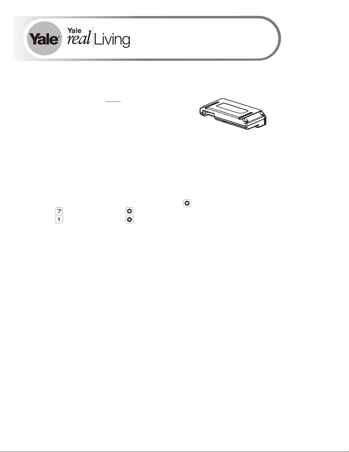
IMPORTANT: the batteries must be removed prior
to removing and/or inserting the network module:
• Remove battery cover and batteries.
• Remove and/or insert Network Module.
• Reinstall batteries and battery cover.
Enrolling the iM1 Network Module:
The Yale iM1 Network Module must be used with a Yale Assure Lock or Yale nexTouch
Lock and cannot be used in conjunction with any other Yale Network Module.
To Enroll the Module:
•Enter the 4-8 digit Master PIN code followed by the key.
•Press the key followed by the key.
•Press the key followed by the key.
Connecting the Yale Secure App with the Yale iM1 Network Module
1. After following steps listed on other side of page for enrolling module, download the Yale Secure
app from App Store®.
2. Ensure Bluetooth® is enabled on your iPhone®, iPad® or iPod touch®, and that you're within a
foot of your Yale lock.
3. Open the Yale Secure app and agree to allow app to access your Home Data.
4. If you do not have a home already created, create a new home when prompted. Tap + to add a
new Yale Lock.
5. The App will search for your Yale Lock. Be sure that you are within close proximity (less than
two feet or so). When "Yale Lock" appears, tap to add.
*If lock does not appear, enter your Master Pin Code on lock keypad, tap gear, tap 7, tap gear,
tap 1 and then tap gear.
6. Scan your Accessory Setup Code; shown below, or manually enter within the app.
Accessory Setup Code
P/N AYR202-iM1-INSTAL-FUL Rev E
Page 28

FCC:
Class B Equipment
This equipment has been tested and found to comply with the limits for a Class
B digital device, pursuant to Part 15 of the FCC Rules. These limits are
designed to provide reasonable protection against harmful interference in a
residential installation. This equipment generates, uses, and can radiate radio
frequency energy and, if not installed and used in accordance with the
instructions, may cause harmful interference to radio communications.
However, there is no guarantee that interference will not occur in a particular
installation. If this equipment does cause harmful Interference to radio or
television reception, which can be determined by turning the equipment off and
on, the user is encouraged to try to correct the interference by one or more of
the following measures:
Ÿ Reorient or relocate the receiving antenna.
Ÿ Increase the separation between the equipment and receiver.
Ÿ Connect the equipment into an outlet on a circuit different from that to
which the receiver is connected.
Ÿ Consult the dealer or an experienced radio/TV technician for help.
THIS DEVICE COMPLIES WITH PART 15 OF THE FCC RULES. OPERATION IS SUBJECT
TO THE FOLLOWING TWO CONDITIONS. (1) THIS DEVICE MAY NOT CAUSE HARMFUL
INTERFERENCE, AND (2) THIS DEVICE MUST ACCEPT ANY INTERFERENCE RECEIVED,
INCLUDING INTERFERENCE THAT MAY CAUSE UNDESIRED OPERATION.
This equipment complies with FCC radiation exposure limits set forth for an
uncontrolled environment. This equipment should be installed and operated with
minimum distance 20cm between the radiator & your body.
Industry Canada:
Section 7.1.2 of RSS-GEN Under Industry Canada regulations, this radio transmitter
may only operate using an antenna of a type and maximum (or lesser) gain
approved for the transmitter by Industry Canada. To reduce potential radio
interference to other users, the antenna type and its gain should be so chosen that
the equivalent isotropically radiated power (e.i.r.p.) is not more than that necessary
for successful communication.
En vertu des règlements d'Industrie Canada, cet émetteur radio ne peut fonctionner
avec une antenne d'un type et un maximum (ou moins) approuvés pour gagner de
l'émetteur par Industrie Canada. Pour réduire le risque d'interférence aux autres
utilisateurs, le type d'antenne et son gain doivent être choisies de façon que la
puissance isotrope rayonnée équivalente (PIRE) ne dépasse pas ce qui est
nécessaire pour une communication réussie.
Section 7.1.3 of RSS-GEN This Device complies with Industry Canada Licenseexempt RSS standard(s). Operation is subject to the following two conditions: 1) this
device may not cause interference, and 2) this device must accept any interference,
including interference that may cause undesired operation of the device.
Cet appareil est conforme avec Industrie Canada RSS standard exemptes de
licence(s). Son fonctionnement est soumis aux deux conditions suivantes: 1) ce
dispositif ne peut causer des interférences, et 2) cet appareil doit accepter toute
interférence, y compris les interférences qui peuvent causer un mauvais
fonctionnement du dispositif.
CAN ICES-3B/NMB-3B
Warning: Changes or modifications to this device, not expressly approved by ASSA ABLOY Residential Group
could void the user's authority to operate the equipment.
Product Support Tel 1-855-213-5841 • www.yalehome.com
Yale®, Yale Real Living® and Assure Lock® are registered trademarks of ASSA ABLOY Residential Group. nexTouch™ is a trademark of ASSA ABLOY Residential Group. Other products’ brand names may be trademarks or registered
Apple®, iPhone®, iPad®, iPod touch® and Siri® are trademarks of Apple Inc., registered in the U.S. and other countries. HomeKit is a trademark of Apple Inc. Use of the Works with Apple HomeKit logo means that an electronic accessory
has been designed to connect specifically to iPod touch, iPhone or iPad, respectively, and has been certified by the developer to meet Apple performance standards. Apple is not responsible for the operation of this device or its compliance
with safety and regulatory standards. Use of the HomeKit logo means that an electronic accessory has been designed to connect specifically to iPod, iPhone, or iPad, respectively, and has been certified by the developer to meet Apple
performance standards. Apple is not responsible for the operation of this device or its compliance with safety and regulatory standards. Please note that the use of this accessory with iPod, iPhone, or iPad may affect wireless performance.
trademarks of their respective owners and are mentioned for reference purposes only. Copyright © 2019, ASSA ABLOY Residential Group. All rights reserved.
Reproduction in whole or in part without the express written permission of ASSA ABLOY Residential Group is prohibited.
 Loading...