

Page 1
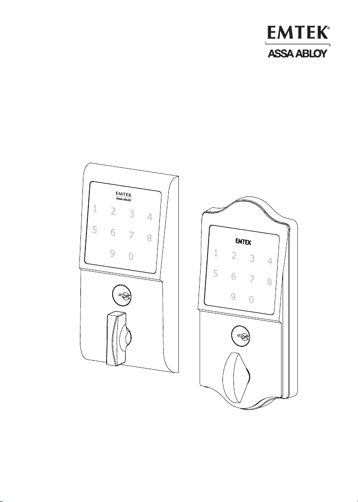
Installation & Programming Guide
EMTouch™ & EMTouch™ Classic Style
Electronic Deadbolt Locksets
EMTouch™
EMTouch™ Classic Style
ASSA ABLOY, the global leader in door opening solutions
Page 2
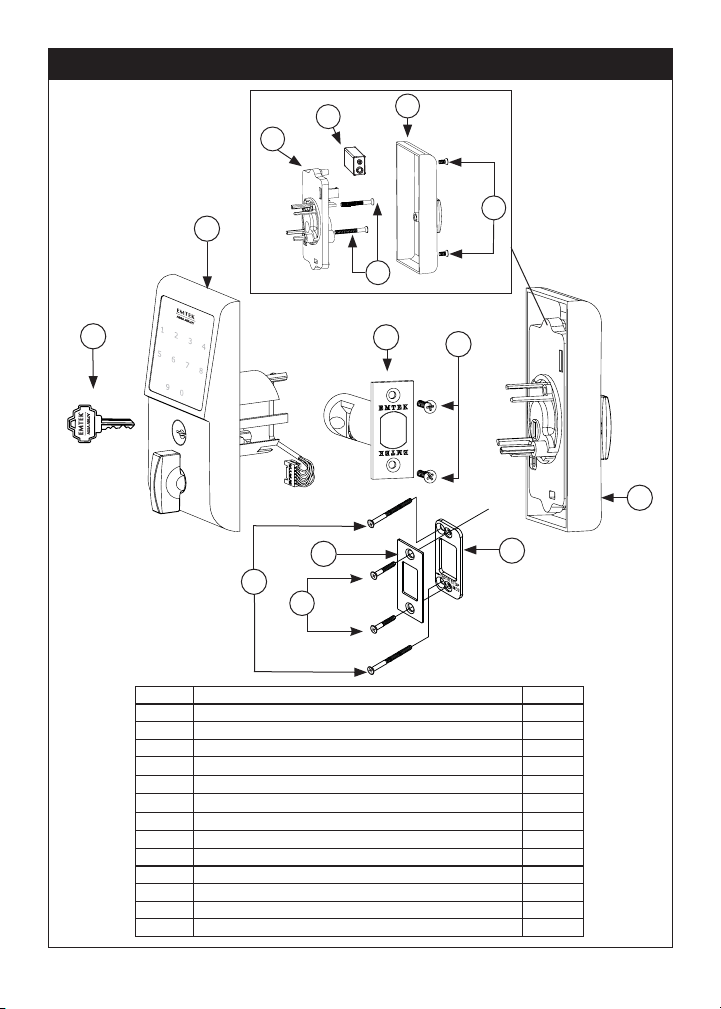
What’s in the Box
4d
4a
4b
4c
2
5
1
3
6
4
7
8
9
6
ITEM NO. DESCRIPTION QTY.
1 Key 2
2 Outside Trim Plate Assembly 1
3 Deadbolt Latch Assembly 2 3/8” or 2 ¾” Backset 1
4 Inside Trim Plate Assembly 1
4a Inside Chassis
4b Inside Trim Plate
#8-32 x 3/8” Flat Head Machine Screw 2
4c
9V Alkaline Battery 1
4d
5 #8-32 x 1½” Flat Head Machine Screw 2
6 #8 x ¾” Wood Screw 4
7 Strike Plate 1
8 Security Plate 1
9 #10 x 3” Wood Screw 2
1
1
2
Page 3
Preparation
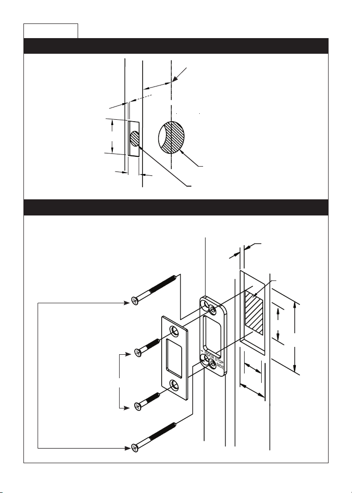
1. Door Prep
2-3/8” or 2-3/4” Backset
1/8” Deep
2 ¼”
2 1/8” Diameter Bore
1 “
1” Diameter Edge Bore
2. Door Jamb Prep
Step 1: Fasten Security Plate using two #10 x 3” Wood Screws (item #9).
Step 2: Fasten Strike Plate using two #8 x ¾” Wood Screws (item #6).
#10 x 3” Wood Screws
3/16” Deep
1¼” Deep
#8 x ¾” Wood Screws
¾”
1 1/8”
1¼”
2-3/4"
2 ¾”
3
Page 4
How to Install
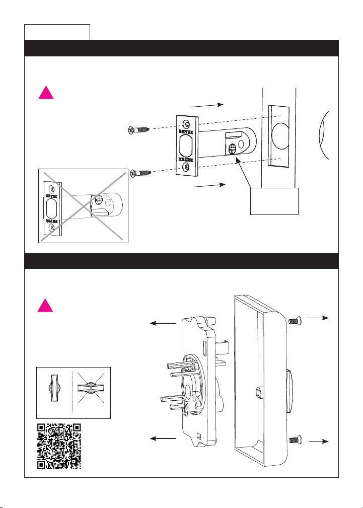
1. Install Latch
Fasten Latch using two #8 x ¾” Wood Screws (item #6).
!
THE LATCH ASSEMBLY
MUST BE ORIENTED
AS SHOWN AND THE
BOLT MUST BE IN THE
RETRACTED POSITION
FOR INSTALLATION.
Crosshairs
at bottom.
2. Remove Screws from Inside Trim Plate
Use a Phillips head screwdriver to remove screws (item #4c) shown below and
detach Inside Trim Plate from the Inside Chassis.
!
REMOVE INSIDE CHASSIS
FROM TRIM PLATE BEFORE
INSTALLING THE OUTSIDE
TRIM. THUMBTURN MUST
BE IN UNLOCKED POSITION.
screws
(item #4c)
Unlocked Locked
4
Scan
this QR
code for
details.
Page 5
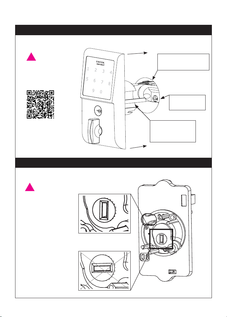
3. Install Outside Trim Plate Assembly
Position the Outside Trim Plate Assembly through the bore hole.
!
ONCE POSITIONED,
OUTSIDE TRIM PLATE
ASSEMBLY REQUIRES
SUPPORT.
Scan
this QR
code for
details.
4. Install Inside Chassis
Step 1: Confirm the position of Flat Shaft.
!
HOLE FOR FLAT
SHAFT MUST BE IN
VERTICAL POSITION
FOR INSTALLATION.
√ Correct for Installation.
Feed wire harness
through the bore hole.
Fit Flat Shaft
through latch.
Flat Shaft must be
in vertical position
for installation.
X Incorrect for Installation.
5
Page 6
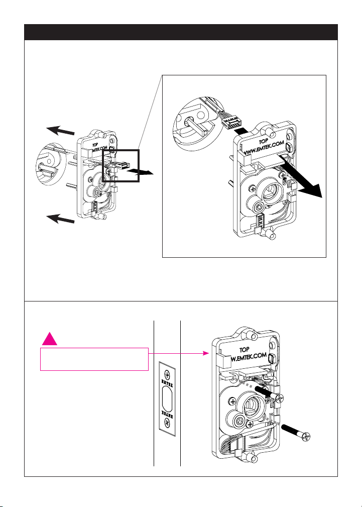
4. Install Inside Chassis
Step 2: Feed the Wire Harness through Inside Chassis.
Step 3: Fasten Inside Chassis using two #8-32 x 1½” Flat Head Machine Screws (item #5).
!
CHECK ALIGNMENT BEFORE
FULLY TIGHTENING SCREWS.
6
Page 7
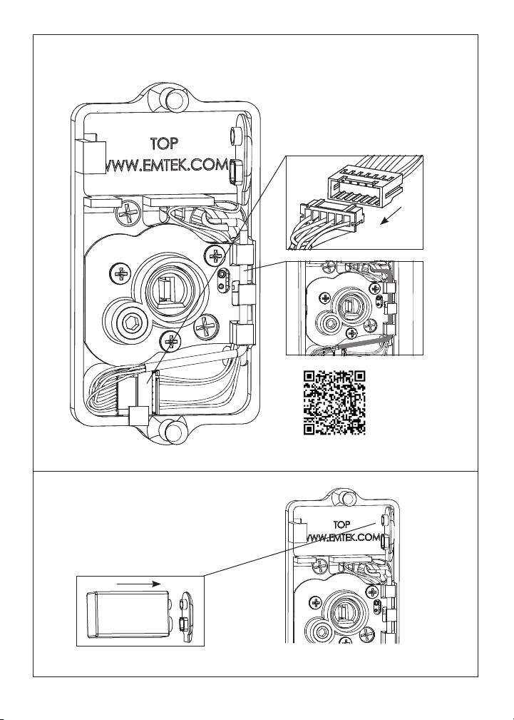
Step 4: Connect Wire Harness (A) and tuck Connectors as shown (B).
Scan
this QR
code for
details.
A
B
Step 5: Install Battery.
9V Battery
For optimal performance, always use a good quality battery.
7
Page 8
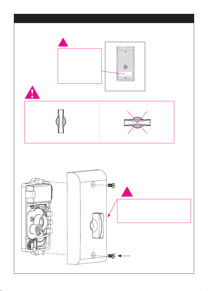
5. Install Inside Trim Plate
Fasten Inside Trim Plate using two #8-32 x 3/8” Flat Head Machine Screws
(item #4c).
!
USER CODES
ARE LOCATED
ON THE INSIDE
TRIM PLATE &
ON PAGE 11.
Inside
Correct for installation
*Unlocked
*Unlocked position is required for installation and removal of the Inside
Trim Plate Assembly.
Incorrect for installation
Locked
!
THUMBTURN MUST BE IN
UNLOCKED POSITION FOR
INSTALLATION.
Screws (item #4c)
8
Page 9
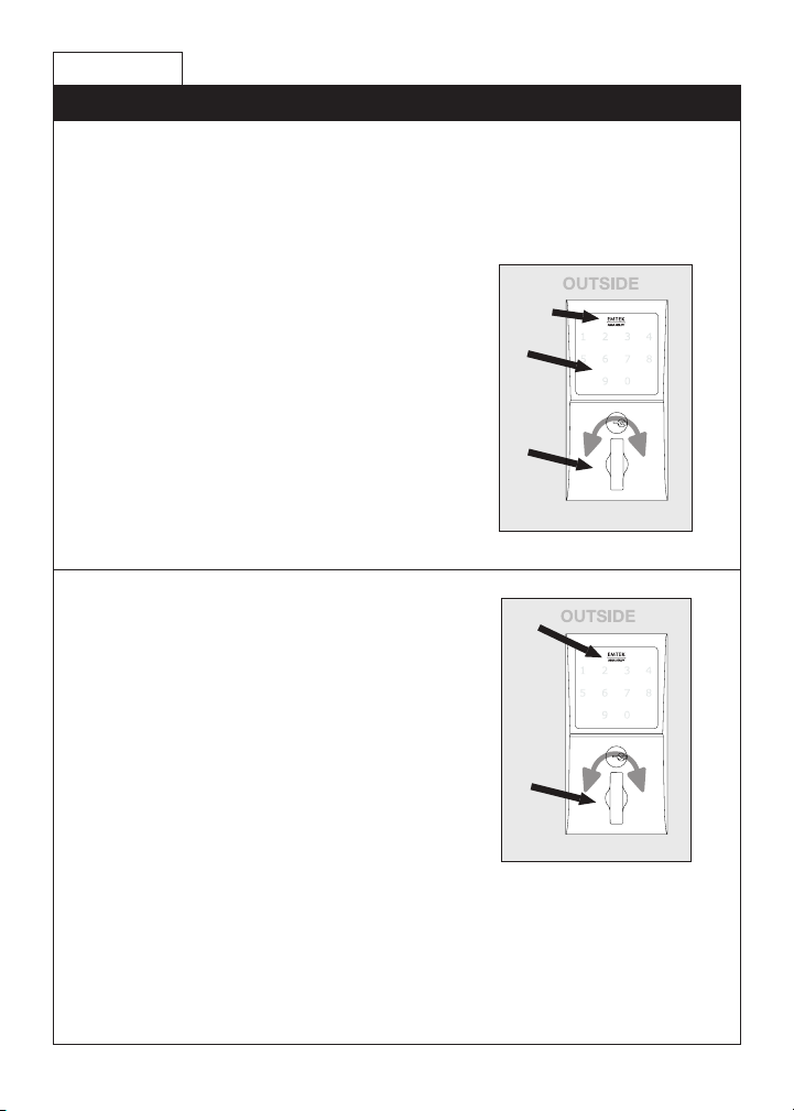
How to Use
Your Lock is Ready to Use
Your Emtek lock is shipped with two 4-digit user codes and a 6-digit
programming code. These codes are randomly generated at the factory.
(Turn to next page for Programming Instructions.)
To Unlock:
1
1. Press EMTEK key or touch
3 ngers across screen.
2. Enter 4-digit user codes.
(See sticker located on the inside
trim plate or on page 11).
3. Rotate Thumbturn.
2
3
To Lock:
Option 1
1. Press EMTEK key.
2. Rotate Thumbturn.
Option 2
1. Touch 3 ngers across screen.
2. Enter 4-digit user codes.
(See sticker located on the inside
trim plate or on page 11).
3. Rotate Thumbturn.
1
2
9
Page 10
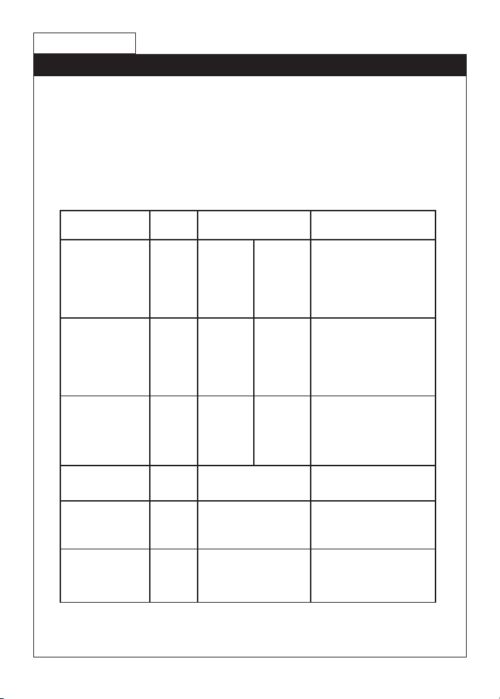
How to Program
Programming Your Lock
In order to perform each of the following six functions, the lock must rst be
placed in Programming Mode:
1. Press and hold EMTEK button for 3 seconds
2. Yellow LED ashes, then remains solid*, number keys also illuminate
3. Enter Programming Code
4. Yellow LED ashes, then 1 beep
5. Yellow LED remains solid (awaiting button press; see following Table)
If you wIsh to Press
ActIons IndIcAtors
Button
Change
Programming
Code
1
Enter New
Programming
Code
(6 digits)
(6 digits)
Add User Code
(4 digits)
Enter New
2
User Code
(4 digits)
(Store up to 20
User Codes)
Delete User Code 3
Enable/Disable
**
All User Codes
Delete All User
Enter User
Code to be
Deleted
Entering ‘4’ disables all Users
4
5
(enables all if disabled)
Re-Enter Programming Code
Codes
Turn Beeper On/
Entering ‘6’ turns OFF (or ON)
6
Off
*If no input within 20 seconds, Yellow LED goes out, Red LED ashes and lock exits Programming Mode.
**Also referred to as “vacation mode”. This command temporarily disables all user codes (metal key
override will still work).
Re-Enter
New
Programming
Code
(6 digits)
Re-Enter
New User
Code
(4 digits)
Re-Enter
User Code to
be Deleted
• 1 Green LED ash
• 1 beep
• 1 Green LED ash
• 1 beep
• 2 Green LED ashes
• 2 beeps
• 1 Green LED ash
• 1 beep
• 1 Green LED ash
• 1 beep
• 2 Green LED ashes
• 2 beeps
• 1 Green LED ash
• 1 beep
• 1 Green LED ash
• 1 beep
• 2 Green LED ashes
• 2 beeps
• 2 Green LED ashes
• 2 beeps
• 1 Green LED ash
• 1 beep
• 2 Green LED ashes
• 2 beeps
• 1 Green LED ash
• 1 beep
• 2 Green LED ashes
• 2 beeps
10
Page 11
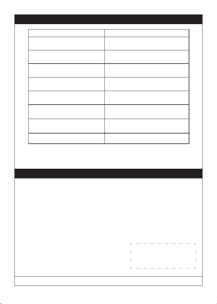
Keypad Operation - Beeper & LED Indicators
Function Indicators
Valid Code • 1 short beep, EMTEK button ashes
Invalid Code/Access Denied* • 1 Red LED ash
Lock-Out Mode Error • 2 short beeps
Access Accepted • 1 short beep
Low Battery • 4 Red LED ashes
Blackout Battery
Button Press Accepted • 1 Yellow LED ash
Outside Thumb Turn Enabled • 2 Green LED ashes
* If 3 consecutive incorrect codes are entered, the lock emits 4 short beeps and a ashing Red EMTEK
button. The lock will not accept additional input for 20 seconds (20 beeps). When the next valid code is
entered the lock will beep quickly 5 times to alert of the incorrect codes.
Battery voltage has dropped too low; keypad will be disabled but metal key override will still work.
**
**
Green.
• 2 short beeps
• 1 short beep per second for duration
• 1 Green LED ash
• 4 short beeps
• 1 long Red LED ash
• 4 long beeps
• 1 Short Beep
Restoring the Lock to Factory Default Setting
This procedure clears the lock of all users and restores the Programming Code and
2 User Codes shipped with the lock.
• Press and hold EMTEK button for 3 seconds.
• Enter “000000”
• After 2 beeps and 2 Green LED Flash, remove power (disconnect 9V battery)
from Lock.
• After 5 seconds, restore power (reconnect 9V battery)
• Conrm by 2 beeps and 2 Green LED Flash.
U.S. patent: 8,141,400
International patents pending.
Place Sticker Here
IN8-EMTOUCHDB 06/24/2013
11
Page 12

Scan this QR for
installation videos
ASSA ABLOY is the global leader in door opening solutions, dedicated to satisfying end-user needs for security, safety and
convenience.
Copyright © 2012, Emtek Products, Inc. an ASSA ABLOY Group company. All rights reserved. Reproduction in whole or in part
without the express written permission of Emtek Products, Inc. is prohibited.
 Loading...