


Z97 Pro4Z97 Pro4
Z97 Pro4Z97 Pro4

Version 1.1
Published May 2014
Copyright©2014 ASRock INC. All rights reserved.
Copyright Notice:
No part of this documentation may be reproduced, transcribed, transmitted, or
translated in any language, in any form or by any means, except duplication of
documentation by the purchaser for backup purpose, without written consent of
ASRock Inc.
Products and corporate names appearing in this documentation may or may not
be registered trademarks or copyrights of their respective companies, and are used
only for identication or explanation and to the owners’ benet, without intent to
infringe.
Disclaimer:
Specications and information contained in this documentation are furnished for
informational use only and subject to change without notice, and should not be
constructed as a commitment by ASRock. ASRock assumes no responsibility for
any errors or omissions that may appear in this documentation.
With respect to the contents of this documentation, ASRock does not provide
warranty of any kind, either expressed or implied, including but not limited to
the implied warranties or conditions of merchantability or tness for a particular
purpose.
In no event shall ASRock, its directors, ocers, employees, or agents be liable for
any indirect, special, incidental, or consequential damages (including damages for
loss of prots, loss of business, loss of data, interruption of business and the like),
even if ASRock has been advised of the possibility of such damages arising from any
defect or error in the documentation or product.
is device complies with Part 15 of the FCC Rules. Operation is subject to the following
two conditions:
(1) this device may not cause harmful interference, and
(2) this device must accept any interference received, including interference that
may cause undesired operation.
CALIFORNIA, USA ONLY
e Lithium battery adopted on this motherboard contains Perchlorate, a toxic substance
controlled in Perchlorate Best Management Practices (BMP) regulations passed by the
California Legislature. When you discard the Lithium battery in California, USA, please
follow the related regulations in advance.
“Perchlorate Material-special handling may apply, see ww w.dtsc.ca.gov/hazardouswaste/
perchlorate”
ASRock Website: http://www.asrock.com

e terms HDMI™ and HDMI High-Denition Multimedia Interface, and the HDMI
logo are trademarks or registered trademarks of HDMI Licensing LLC in the United
States and other countries.

Contents
Chapter 1 Introduction 1
1.1 Package Contents 1
1.2 Specications 2
1.3 Motherboard Layout 6
1.4 I/O Panel 8
Chapter 2 Installation 10
2.1 Installing the CPU 11
2.2 Installing the CPU Fan and Heatsink 14
2.3 Installing Memory Modules (DIMM) 15
2.4 Expansion Slots (PCI and PCI Express Slots) 17
2.5 Jumpers Setup 18
2.6 Onboard Headers and Connectors 19
2.7 CrossFireX
TM
and Quad CrossFireXTM Operation Guide 24
2.7.1 Installing Two CrossFireX
TM
-Ready Graphics Cards 24
2.7.2 Driver Installation and Setup 26
2.8 M.2_SSD (NGFF) Module Installation Guide 27
Chapter 3 Software and Utilities Operation 30
3.1 Installing Drivers 30
3.2 A-Tuning 31
3.3 Intel® Rapid Start Technology 37
3.4 Intel® Smart Connect Technology 42
3.5 ASRock APP Shop 47
3.5.1 UI Overview 47

3.5.2 Apps 48
3.5.3 BIOS & Drivers 51
3.5.4 Setting 52
3.6 Start8 53
Chapter 4 UEFI SETUP UTILITY 56
4.1 Introduction 56
4.1.1 UEFI Menu Bar 56
4.1.2 Navigation Keys 57
4.2 Main Screen 58
4.3 OC Tweaker Screen 59
4.4 Advanced Screen 68
4.4.1 CPU Conguration 69
4.4.2 Chipset Conguration 71
4.4.3 Storage Conguration 73
4.4.4 Intel® Rapid Start Technology 75
4.4.5 Intel® Smart Connect Technology 76
4.4.6 Intel® Thunderbolt™ 77
4.4.7 Super IO Conguration 78
4.4.8 ACPI Conguration 79
4.4.9 USB Conguration 81
4.4.10 Trusted Computing 83
4.5 Tools 84
4.6 Hardware Health Event Monitoring Screen 87
4.7 Boot Screen 88

4.8 Security Screen 91
4.9 Exit Screen 92

1
English
Z97 Pro4
Chapter 1 Introduction
ank you for purchasing ASRock Z97 Pro4 motherboard, a reliable motherboard
produced under ASRock ’s consistently stringent quality control. It delivers excellent
performance with robust design conforming to ASRock ’s commitment to quality
and endurance.
In this manual, Chapter 1 and 2 contains the introduction of the motherboard
and step-by-step installation guides. Chapter 3 contains the operation guide of the
soware and utilities. Chapter 4 contains the conguration guide of the BIOS setup.
1.1 Package Contents
•
ASRock Z97 Pro4 Motherboard (ATX Form Factor)
•
ASRock Z97 Pro4 Quick Insta llation Guide
•
ASRock Z97 Pro4 Support CD
•
2 x Serial ATA (SATA) Data Cables (Optional)
•
1 x I/O Panel Shield
•
1 x Screw for M.2_SSD (NGFF) Socket 3
Becau se the motherboard specications and the BIOS soware might be updated, the
content of this manual will be subject to change without notice. In ca se any modications of this manual occur, the updated version will be available on ASRo ck’s website
without furth er notice. If you require technical suppor t related to this motherboard,
please visit our website for spe cic information about the model you are using. You
may nd the l atest VGA cards and CPU suppor t list on ASRock’s website a s well.
ASRock website http://www.asrock.com.

2
English
1.2 Specications
Platform
•
ATX Form Factor
•
High Density Glass Fabric PCB
CPU
•
Supports 5th Generation, New 4th and 4th Generation Intel®
Core™ i7/i5/i3/Pentium®/Celeron® Processors (Socket 1150)
•
Digi Power design
•
6 Power Phase design
•
Supports Intel® Turbo Boost 2.0 Technology
•
Supports Intel® K-Series unlocked CPUs
•
Supports ASRock BCLK Full-range Overclocking
Chipset
•
Intel® Z97
Memory
•
Dual Channel DDR3 Memory Technolog y
•
4 x DDR3 DIMM Slots
•
Supports DDR3 3100+(OC)/2933(OC)/2800(OC)/2400(OC)/
2133(OC)/ 1866(OC)/1600/1333/1066 non-ECC, un-buered
memory
•
Max. capacity of system memory: 32GB (see CAUTION)
•
Supports Intel® Extreme Memory Prole (XMP) 1.3 / 1.2
Expansion
Slot
•
1 x PCI Express 3.0 x16 Slot (PCIE1: x16 mode)
•
1 x PCI Express 2.0 x16 Slot (PCIE3: x4 mode)
* If PCIE2 or PCIE4 slot is occupied, PCIE3 slot will run at x2
mode.
•
2 x PCI Express 2.0 x1 Slots
•
2 x PCI Slots
•
Supports AMD Quad CrossFireXTM and CrossFireXTM
Graphics
•
Intel® HD Graphics Built-in Visuals and the VGA outputs can
be supported only with processors which are GPU integrated.
•
Supports Intel® HD Graphics Built-in Visuals : Intel® Quick
Sync Video with AVC, MVC (S3D) and MPEG-2 Full
HW Encode1, Intel® InTru
TM
3D, Intel® Clear Video HD
Technology, Intel® InsiderTM, Intel® HD Graphics 4400/4600
•
Pixel Shader 5.0, DirectX 11.1
•
Max. shared memory 1792MB

3
English
Z97 Pro4
•
ree graphics output options: D-Sub, DVI-D and HDMI
•
Supports Triple Monitor
•
Supports HDMI with max. resolution up to 1920x1200 @
60Hz
•
Supports DVI-D with ma x. resolution up to 1920x1200 @
60Hz
•
Supports D-Sub with max. resolution up to 1920x1200 @
60Hz
•
Supports Auto Lip Sync, Deep Color (12bpc), xvYCC and
HBR (High Bit Rate Audio) with HDMI Port (Compliant
HDMI monitor is required)
•
Supports HDCP with DVI-D and HDMI Ports
•
Supports Full HD 1080p Blu-ray (BD) playback with DVI-D
and HDMI Ports
Audio
•
7.1 CH HD Audio with Content Protection (Realtek ALC892
Audio Codec)
•
Premium Blu-ray Audio support
•
Supports Surge Protection (ASRock Full Spike Protection)
•
Nichicon Fine Gold Series Audio Caps
LAN
•
Gigabit LAN 10/100/10 00 Mb/s
•
Giga PHY Intel® I218V
•
Supports Intel® Remote Wake Technology
•
Supports Wake-On-LAN
•
Supports Lightning/ESD Protection (ASRock Full Spike
Protection)
•
Supports Energy Ecient Ethernet 802.3az
•
Supports PXE
Rear Panel
I/O
•
1 x PS/2 Mouse/Keyboard Port
•
1 x D-Sub Port
•
1 x DVI-D Port
•
1 x HDMI Port
•
1 x Optical SPDIF Out Port
•
4 x USB 2.0 Ports (Supports ESD Protection (ASRock Full
Spike Protection))
•
4 x USB 3.0 Ports (Supports ESD Protection (ASRock Full
Spike Protection))

4
English
•
1 x RJ-45 LAN Port with LED (ACT/LINK LED and SPEED
LE D)
•
HD Audio Jacks: Rear Speaker / Centra l / Bass / Line in /
Front Speaker / Microphone
Storage
•
6 x SATA3 6.0 Gb/s Connectors, support RAID (RAID 0,
RAID 1, RAID 5, RAID 10, Intel Rapid Storage Technology
13 and Intel Smart Response Technology), NCQ, AHCI and
Hot Plug
•
1 x SATA Express Connector (shared with SATA3_4,
SATA3_5 and M.2_ SSD (NGFF) Socket 3)
* Support to be announced
•
1 x M.2_SSD (NGFF) Socket 3, supports M.2 SATA3 6.0 Gb/s
module and M.2 PCI Express module up to Gen2 x2 (10 Gb/s)
Connector
•
1 x COM Port Header
•
1 x Chassis Intrusion Header
•
1 x TPM Header
•
1 x Power LED Header
•
2 x CPU Fan Connectors (1 x 4-pin, 1 x 3-pin)
•
2 x Chassis Fan Connectors (1 x 4-pin, 1 x 3-pin)
•
1 x Power Fan Connector (3-pin)
•
1 x 24 pin ATX Power Connector
•
1 x 8 pin 12V Power Connector
•
1 x PCIe Power Connector
•
1 x Front Panel Audio Connector
•
1 x underbolt AIC Connector
•
2 x USB 2.0 Headers (Support 4 USB 2.0 ports) (Supports ESD
Protection (ASRock Full Spike Protection))
•
1 x USB 3.0 Header (Supports 2 USB 3.0 ports) (Supports ESD
Protection (ASRock Full Spike Protection))
BIOS
Feature
•
64Mb AMI UEFI Legal BIOS with multilingual GUI support
•
ACPI 1.1 Compliant wake up events
•
SMBIOS 2.3.1 support
•
CPU, DRAM, PCH 1.05V, PCH 1.5V Voltage Multi-adjust-
ment

5
English
Z97 Pro4
Hardware
Monitor
•
CPU/Chassis temperature sensing
•
CPU/Chassis/Power Fan Tachometer
•
CPU/Chassis Quiet Fan (Auto adjust chassis fan speed by
CPU temperature)
•
CPU/Chassis Fan multi-speed control
•
CASE OPEN detection
•
Voltage monitoring: +12V, +5V, +3.3V, CPU Vcore
OS
•
Microso® Windows® 10 64-bit / 8.1 32-bit / 8.1 64-bit / 8 32-
bit / 8 64-bit / 7 32-bit / 7 64-bit
Certications
•
FCC, CE, WHQL
•
ErP/EuP ready (ErP/EuP ready power supply is required)
* For detailed product information, please visit our website: http://www.asrock .com
Please realiz e that the re is a certain r isk involved with o verclocking, including adjusting the setting in the BIOS, applying Untied Ove rclocking Technology, or using thirdparty o verclocking tools. Overclocking may aect your syste m’s stability, or even cause
damage to the components and dev ices of your system. It should be done at your own
risk and expe nse. We are not responsible for possible damage cau sed by overclocking.
Due to limitation , the actual memory size may be less than 4GB for the re servation
for system usage under Windows® 32- bit operating systems. Windows® 64-bit operating systems do not have such limitations. You can use ASRock XFast RAM to utiliz e
the memory that Windows® cannot use.
6
English
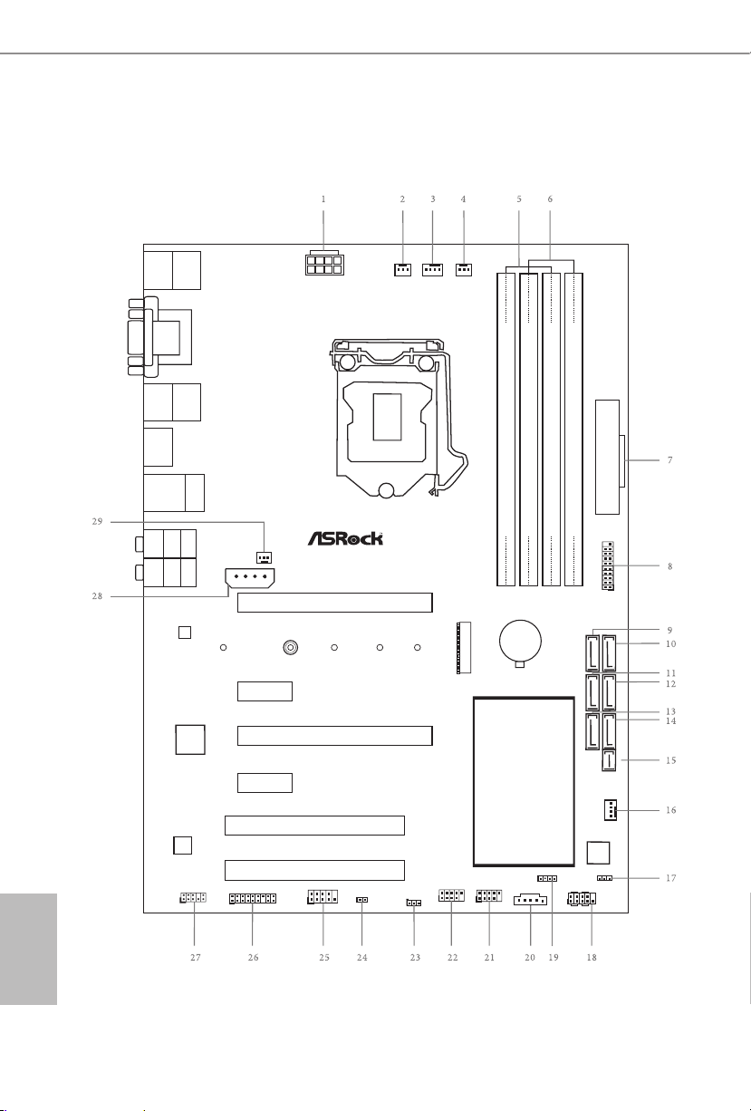
1.3 Motherboard Layout
Intel
Z97
DDR 3_A2 (6 4 bit, 24 0-pin m odule )
DDR 3_A1 (6 4 bit, 24 0-pin m odule )
DDR 3_B2 (6 4 bit, 24 0-pin m odule )
DDR 3_B1 (6 4 bit, 24 0-pin m odule )
ATX12V1
Supe r
I/O
ATXP WR 1
1
USB3_4 _5
PCIE1
PLED1
1
1
SPEAKER1
HDLED R ESET
PLED PWRBTN
PANEL1
1
USB_6_7
1
USB_4_5
1
COM1
1
1
HD_AUDIO1
Z97Pro4
PCIE2
CHA_FAN1
CHA_FAN2
PCI1
RoHS
USB 2. 0
T: USB0
B: USB 1
Ps2
Keyb oard/
Mous e
Top:
RJ-45
USB2.0
T: USB2
B: USB3
Top:
Centr al/Ba ss
Cente r:
REAR SPK
Top:
LINE IN
Cente r:
FRONT
Botto m:
Optic al
SPDIF
Botto m:
MIC IN
USB 3. 0
T: USB0
B: USB 1
HDM I
VGA1
DVI 1
USB 3. 0
T: USB2
B: USB 3
64Mb
BIOS
CPU_FAN1
CPU_FAN2
PWR_FAN1
CMOS
Battery
CLRMOS1
1
1
TPM1
TB1
NUT1
NUT2NUT3NUT4NUT5
M2_ 1
PCIExpress 3.0
Front USB3.0
AUDIO
CODEC
LAN
PCIE3
PCI2
PCIE4
1
CI1
SATA3_0
SATA3_2
SATA3_1
SATA3_3
SATA3_5
SATA3_4
SATAE_1
PCIE_PWR1

7
English
Z97 Pro4
No. Description
1 ATX 12V Power Connector (ATX12V1)
2 Power Fan Connector (PWR_FAN1)
3 CPU Fan Connector (CPU_FAN1)
4 CPU Fan Connector (CPU_FAN2)
5 2 x 240-pin DDR3 DIMM Slots (DDR3_A1, DDR3_B1)
6 2 x 240-pin DDR3 DIMM Slots (DDR3_A2, DDR3_B2)
7 ATX Power Connector (ATXPWR1)
8 USB 3.0 Header (USB3_4_5)
9 SATA3 Connector (SATA3_0)
10 SATA3 Connector (SATA3_3)
11 SATA3 Connector (SATA3_1)
12 SATA3 Connec tor (SATA 3_4)
13 SATA3 Connector (SATA3_2)
14 SATA3 Connector (SATA3_5)
15 SATA Express Connector (SATAE_1)
16 Chassis Fan Connector (CHA_FAN1)
17 Power LED Header (PLED1)
18 System Panel Header (PANEL1)
19 Chassis Speaker Header (SPEAKER1)
20 underbolt AIC Connector (TB1)
21 USB 2.0 Header (USB_4_5)
22 USB 2.0 Header (USB_6_7)
23 Clear CMOS Jumper (CLRCMOS1)
24 Chassis Intrusion Header (CI1)
25 COM Port Header (COM1)
26 TPM Header (TPM1)
27 Front Panel Audio Header (HD_AUDIO1)
28 PCIe Power Connector (PCIE_PWR1)
29 Chassis Fan Connector (CHA_FAN2)
8
English
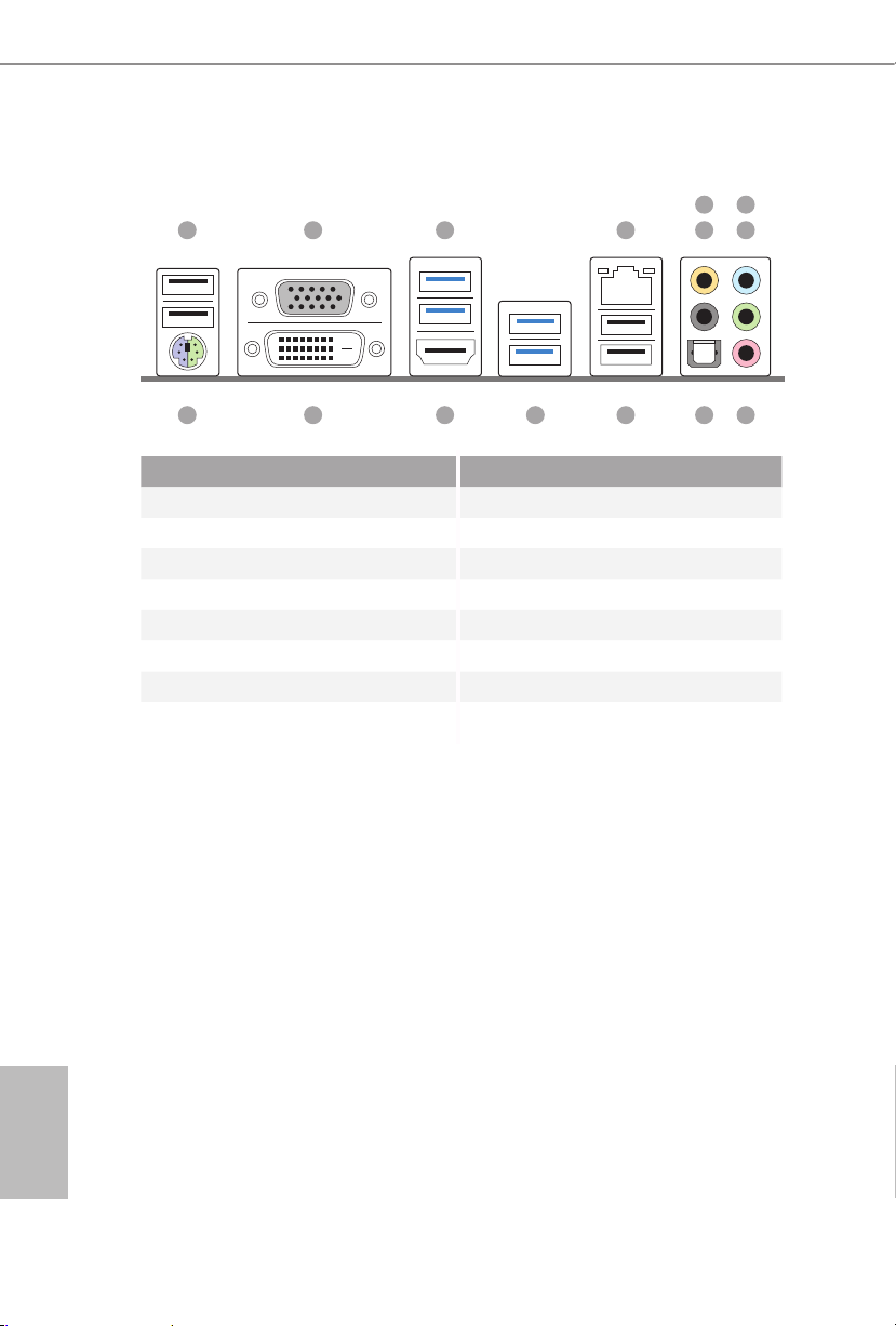
1.4 I/O Panel
No. Description No. Description
1 USB 2.0 Ports (USB01) 9 Microphone (Pink)
2 D-Sub Port 10 Optical SPDIF Out Port
3 USB 3.0 Ports (USB3_0_1) 11 USB 2.0 Ports (USB23)
4 LAN RJ-45 Port* 12 USB 3.0 Ports (USB3_2_3)
5 Central / Bass (Orange) 13 HDMI Port
6 Rear Speaker (Black) 14 DVI-D Port
7 Line In (Light Blue) 15 PS/2 Mouse/Keyboard Port
8 Front Speaker (Lime)**
1 2 3 4 6
91015 11121314
587

9
English
Z97 Pro4
* ere are two LEDs on each LAN port. Please refer to the table below for the LAN port LED indications.
Activity / Link LED Speed LED
Status Description Status Description
O No Link O 10Mbps connection
Blinking Data Activity Orange 100Mbps connection
On Link Green 1Gbps connection
** If you use a 2- channel speaker, plea se connect the speake r’s plug into “Front Speaker Jack”. See the table below
for connection d etails in accordance w ith the type of speaker you use.
Audio Output
Channels
Front Speaker
(No. 8)
Rear Speaker
(No. 6)
Central / Bass
(No. 5)
Line In
(No. 7)
2 V -- -- --
4 V V -- --
6 V V V --
8 V V V V
ACT/LINK LED
SPEED LED
LAN Por t
To enable Multi-Streaming, you need to connect a front panel audio cable to the front
panel au dio header. Aer re starting your computer, you will nd the “Mixer” tool on
your system. Please select “Mixer ToolBox” , click “Enable playback multi-streaming”, and click “ok”. Choose “2CH”, “4CH”, “6CH”, or “8CH” and the n you are allowed
to select “Realtek HDA Primary output” to use the Rear Speaker, Central/Bass, and
Front Speaker, or select “Realtek HDA Audio 2nd output” to use the f ront panel audio.

10
English
is is an ATX form factor motherboard. Before you install the motherboard, study
the conguration of your chassis to ensure that the motherboard ts into it.
Pre-installation Precautions
Take note of the following precautions before you install motherboard components
or change any motherboard settings.
•
Make sure to unplug the power cord before installing or removing the motherboard
components. Failure to do so may cause physical injuries and damages to motherboard
components.
•
In order to avoid damage from static electricity to the motherboard’s components,
NEVER place your motherboard directly on a carpet. Also remember to use a grounded
wrist strap or touch a safety grounded object before you handle the components.
•
Hold components by the edges and do not touch the ICs.
•
Whenever you uninstall any components, place them on a grounded anti-static pad or
in the bag that comes with the components.
•
When placing screws to secure the motherboard to the chassis, please do not over-
tighten the screws! Doing so may damage the motherboard.
Chapter 2 Installation
11
English
Z97 Pro4
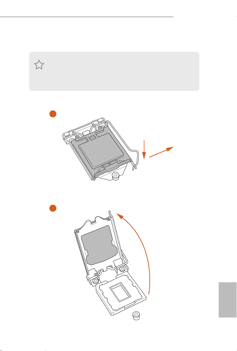
2.1 Installing the CPU
1. Before you inser t the 1150-P in CPU into the socket, plea se check if the PnP c ap is on
the socket, if the CPU surfa ce is unclean, or if there are any bent pins in the socket.
Do not force to insert the CPU into the socket if above situation is found. Otherwise,
the CPU will be seriously damaged .
2. Unplug all power cabl es before installing th e CPU.
2
1
A
B
12
English
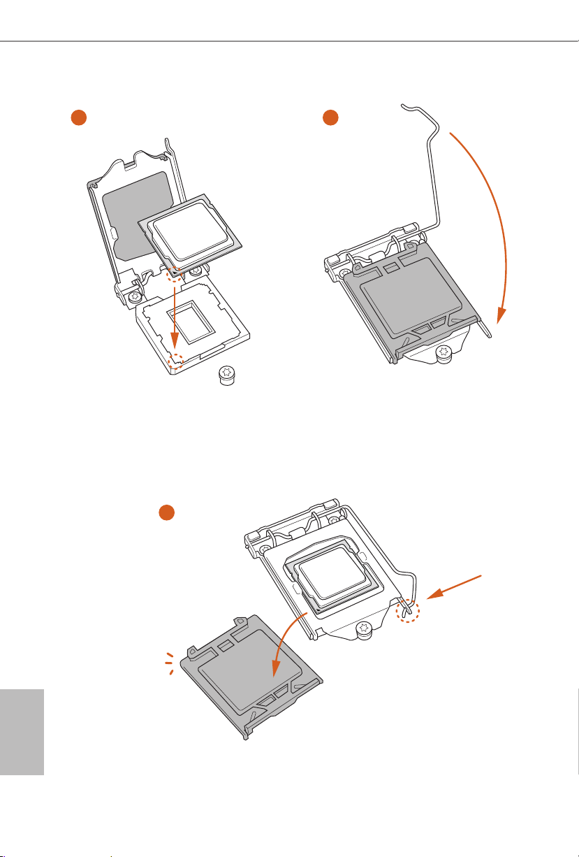
4
5
3

13
English
Z97 Pro4
Please save and replace the cover if the processor i s removed. e cover must be placed
if you wish to retur n the motherboard for aer service.

14
English
2.2 Installing the CPU Fan and Heatsink
1 2
C
P
U
_
FA
N
15
English
Z97 Pro4
2.3 Installing Memory Modules (DIMM)
is motherboard provides four 240-pin DDR3 (Double Data Rate 3) DIMM slots,
and supports Dual Channel Memory Technology.
Dual Channel Memory Conguration
e DIMM only ts in one correct orie ntation. It will cause permanent dam age to
the mothe rboard and the DIMM if you force the DIMM into the slot at incor rect
orientation.
Priority DDR3_A1 DDR3_A2 DDR3_B1 DDR3_B2
1 Populated Populated
2 Populated Populated
3 Populated Populated Populated Populated
1. For dual channel conguration, you always need to install identical (the same
brand, speed , size and chip-type) DDR3 DIMM pairs.
2. It is unable to activate Dual Channel Me mory Technology w ith only one or three
memory module installed.
3. It is not allowed to install a DDR or DDR 2 memory module into a DDR3 slot;
otherwise , this motherboard and DIM M may be damaged.

16
English
1
2
3

17
English
Z97 Pro4
2.4 Expansion Slots (PCI and PCI Express Slots)
ere are 2 PCI slots and 4 PCI Express slots on the motherboard.
PCI slots:
e PCI1 and PCI2 slots are used to install expansion cards that have 32-bit PCI
interface.
PCIe slots:
PCIE1 (PCIe 3.0 x16 slot) is used for PCI Express x16 lane width graphics cards.
PCIE2 (PCIe 2.0 x1 slot) is used for PCI Express x1 lane width cards.
PCIE3 (PCIe 2.0 x16 slot) is used for PCI Express x4 lane width graphics cards.
PCIE4 (PCIe 2.0 x1 slot) is used for PCI Express x1 lane width cards.
PCIe Slot Congurations
PCIE1 PCIE3
Single Graphics Card x16 N/A
Two Graphics Cards in
CrossFireX
TM
Mode
x16 x4
For a better ther mal environme nt, ple ase connect a ch assi s fan to the motherboard’s
chassis fan connector (CHA_ FAN1 or CHA_FAN2) when using multiple g raphics
cards.
Before installing an ex pansion card, please make sure that the power supply is
switched o or the power cord is unplugged. Plea se read the documentation of the
expan sion card and mak e necessary h ardware settings for the card before you start
the installation.
18
English
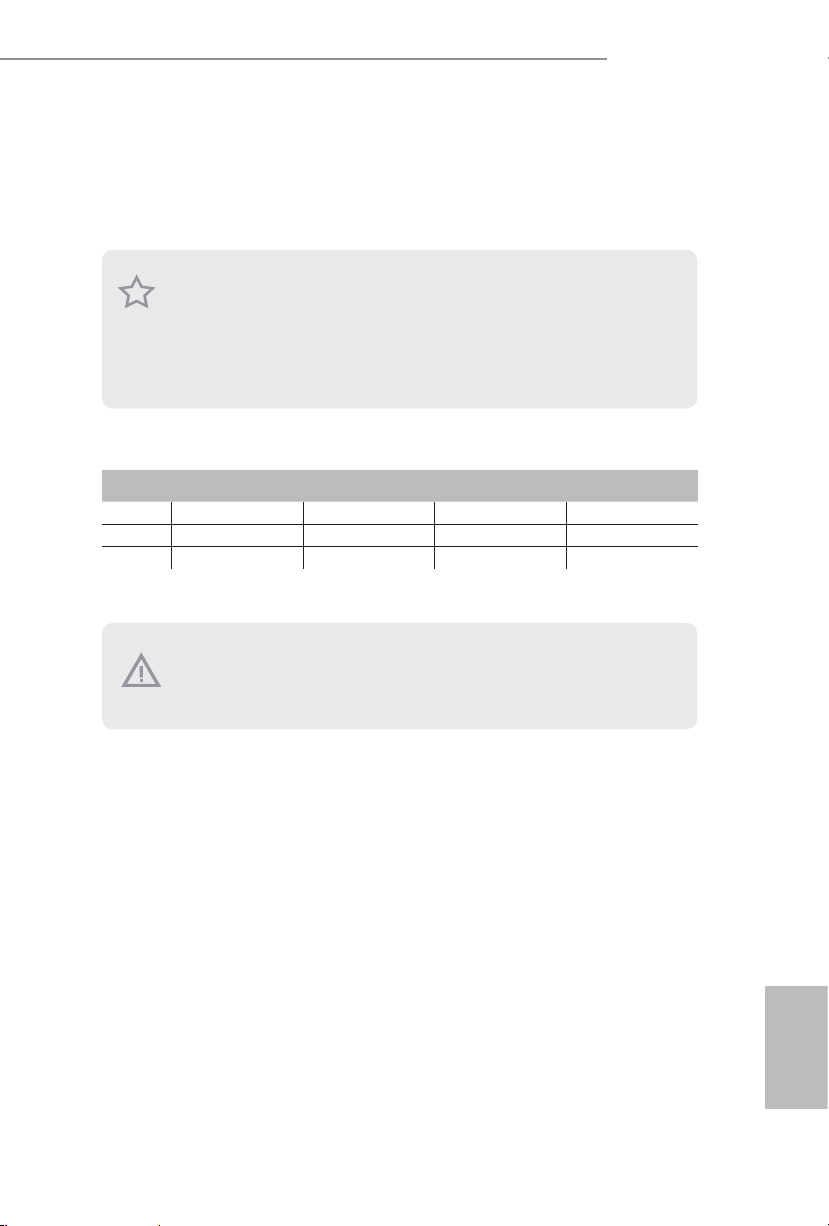
2.5 Jumpers Setup
e illustration shows how jumpers are setup. When the jumper cap is placed on
the pins, the jumper is “Short”. If no jumper cap is placed on the pins, the jumper
is “Open”. e illustration shows a 3-pin jumper whose pin1 and pin2 are “Short”
when a jumper cap is placed on these 2 pins.
Clear CMOS Jumper
(C LRC MO S1)
(see p.10, No. 23)
CLRCMOS1 allows you to clear the data in CMOS. To clear and reset the system
parameters to default setup, please turn o the computer and unplug the power
cord from the power supply. Aer waiting for 15 seconds, use a jumper cap to
short pin2 and pin3 on CLRCMOS1 for 5 seconds. However, please do not clear
the CMOS right aer you update the BIOS. If you need to clear the CMOS when
you just nish updating the BIOS, you must boot up the system rst, and then shut
it down before you do the clear-CMOS action. Please be noted that the password,
date, time, and user default prole will be cleared only if the CMOS battery is
removed.
Clear CMOS
Default
19
English
Z97 Pro4
2.6 Onboard Headers and Connectors
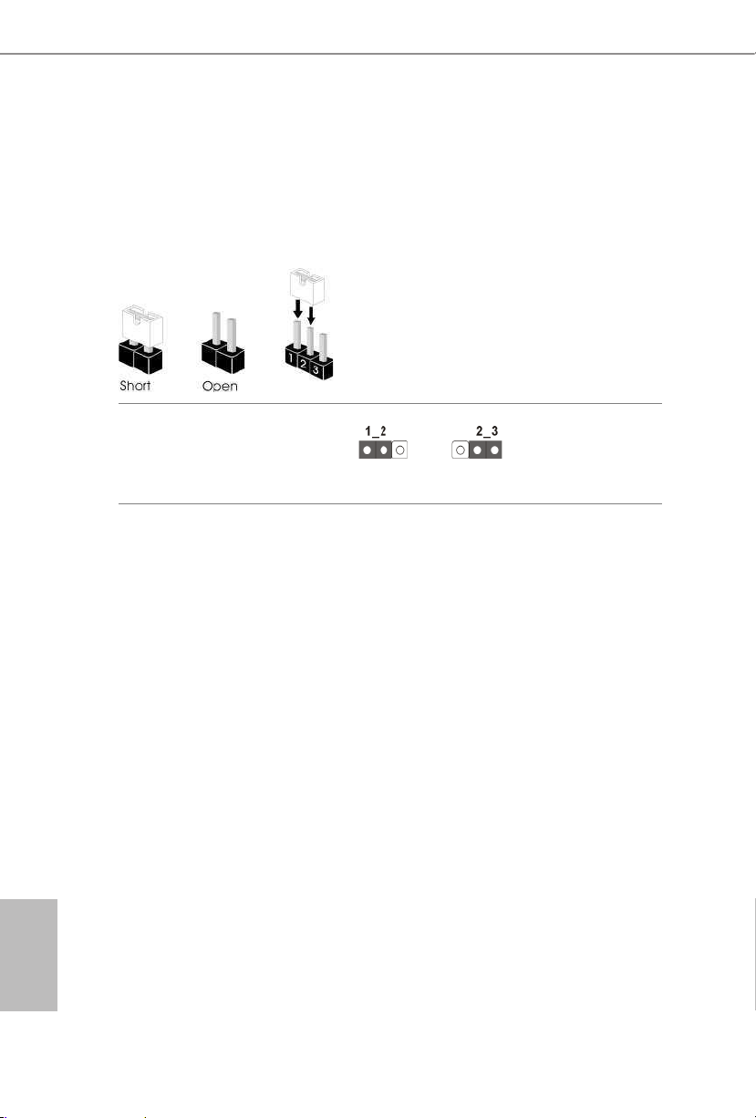
System Panel Header
(9-pi n PANEL1)
(see p.10, No. 18)
Connect the power
switch, reset switch and
system status indicator on
the chassis to this header
according to the pin
assignments below. Note
the positive and negative
pins before connecting
the cables.
PWRBTN (Power Switch):
Connec t to the power switch on the ch assi s front panel. You may congure the way to
turn o your system using the power switch.
RESET (Reset Switch):
Connec t to the reset switch on the chassi s front panel. Press the reset sw itch to restart
the computer if the compute r freezes and fails to perform a norm al restart.
PLED (Syste m Power LED):
Connec t to the power status indicator on the chas sis front panel. e LED i s on when
the system is ope rating. e LED keeps blinking when the system i s in S1/S3 sleep state.
e LED is o when the system i s in S4 sle ep state or powered o (S5).
HDLED (Ha rd Drive Activity LED):
Connec t to the hard drive ac tivity LED on the chassis front panel. e LED is on when
the hard dr ive is reading or w riting data.
e front panel de sign may dier by chassis. A front panel module mainly consists of
power switch, reset sw itch, power LED, hard drive activity LED, speake r and etc. When
connec ting your chassis front panel module to this header, make sure the wire assignments and the pin a ssignments are matche d corre ctly.
Onboard headers and connectors are NOT jump ers. Do NOT place jumper caps over
these headers and connectors. Placing jumper caps over the headers and connectors
will cause permanent damage to the motherboard.
GND
RESET#
PWRBTN#
PLED-
PLED+
GND
HDLED-
HDLED+
1
GND
20
English
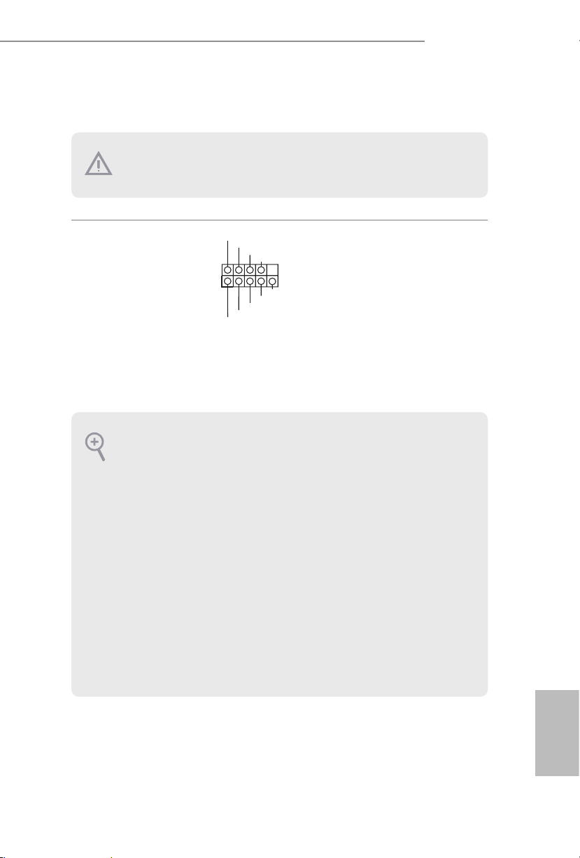
Power LED Header
(3-p in PL ED1)
(see p.10, No. 17)
Please connect the chassis
power LED to this header
to
indicate the system’s
power status.
Serial ATA3 Connectors
(SATA3_0:
see p.10, No. 9)
(SATA3_1:
see p.10, No. 11)
(SATA3_ 2:
see p.10, No. 13)
(SATA3_ 3:
see p.10, No. 10)
(SATA3_4:
see p.10, No. 12)
(SATA3_ 5:
see p.10, No. 14)
ese six SATA3
connectors support SATA
data cables for internal
storage devices with up to
6.0 Gb/s data transfer rate.
e SATA3_4, SATA3_5
are shared with the SATA
Express connector.
Serial ATA Express
Connector
(SATAE_1:
see p.10, No. 15)
Please connect either
SATA or PCIe storage
devices to this connector.
e SATA Express
connector is shared with
the SATA3_4, SATA3_5
and the M.2_ SSD (NGFF)
Socket 3.
*e SATA Express
interface is a combination
of SATAE_1, SATA3_4,
and SATA 3_ 5.
USB 2.0 Headers
(9-pin USB_4_5)
(see p.10, No. 21)
(9-pin USB_6_7)
(see p.10, No. 22)
Besides four USB 2.0 ports
on the I/O panel, there
are two headers on this
motherboard. Each USB
2.0 header can support
two ports.
SATA3_0SATA3_2 SATA3_1
SATA3_3SATA3_5 SATA3_4
1
PLED+
PLED+
PLED-
DUMMY
GND
GND
P+
P-
USB_PWR
P+
P-
USB_PWR
1

21
English
Z97 Pro4
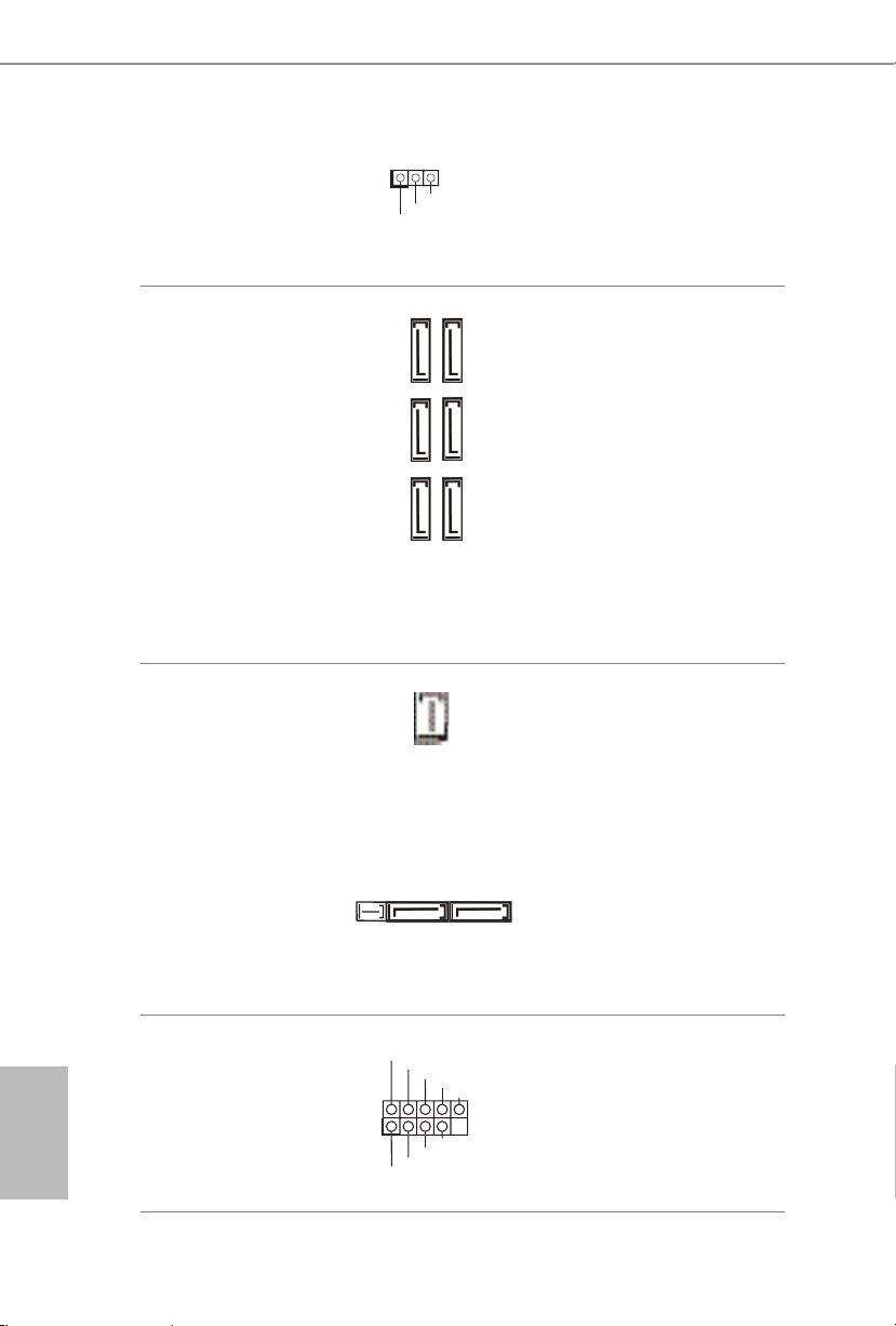
USB 3.0 Header
(19-pin USB3_4_ 5)
(see p.10, No. 8)
Besides four USB 3.0
ports on the I/O panel,
there is one header on this
motherboard. Each USB
3.0 header can support
two ports.
Front Panel Audio Header
(9-pin HD_ AUDIO1)
(see p.10, No. 27)
is header is for
connecting audio devices
to the front audio panel.
Chassis Speaker Header
(4-p i n SPEAKER1)
(see p.10, No. 19)
Please connect the chassis
speaker to this header.
Chassis and Power Fan
Connectors
(4-pin CHA_FAN1)
(see p.10, No. 16)
(3-pi n CHA_FAN2)
(see p.10, No. 29)
Please connect fan cables
to the fan connectors and
match the black wire to
the ground pin.
1. High Denition Audio supports Jack Sensing, but the panel w ire on the chassis must
suppor t HDA to function correctly. Please follow the instructions in our manual and
chassis manual to install your system.
2. If you use an AC’97 audio panel, pl ease install it to the front panel audio header by
the steps below:
A. Connect Mic_IN (MIC) to MIC2_ L.
B. Conne ct Audio_R (RIN) to OUT2_R and Audio_ L (LIN) to OUT2_ L.
C. Connect Ground (GND) to Ground (GND).
D. MIC_ RET and OUT_RET are for the HD audio panel only. You don’t need to connect them for the AC’97 audio panel.
E. To activate the front mic, go to the “FrontMic” Tab in the Realtek Control panel
and adjust “Recording Volume”.
GND
FAN_VOLTAGE
CHA_FAN_SPEED
1
IntA_PB_D+
Dummy
IntA_PB_D-
GND
IntA_PB_SSTX+
GND
IntA_PB_SSTX-
IntA_PB_SSRX+
IntA_PB_SSRX-
VbusVbus
Vbus
IntA_PA_SSRX-
IntA_PA_SSRX+
GND
IntA_PA_SSTX-
IntA_PA_SSTX+
GND
IntA_PA_D-
IntA_PA_D+
J _ S E N S E
O U T 2 _ L
1
MIC_RET
PRESENCE#
GND
OUT2_R
MIC2_R
MIC2_L
OUT_RET
GN D
+12V
FAN_SPEED
FAN_SPEED_CONTROL
1
2
3
4
1
+5V
DUMMY
DUMMY
SPEAKER
22
English
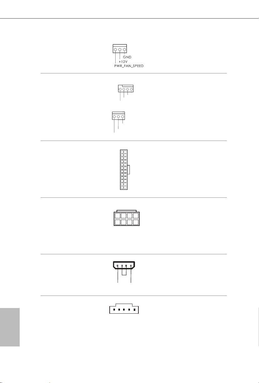
(3-p in PW R_ FA N1)
(see p.10, No. 2)
CPU Fan Connectors
(4-pin CPU_FAN1)
(see p.10, No. 3)
(3-pin CPU_FAN2)
(see p.10, No. 4)
is motherboard pro-
vides a 4-Pin CPU fan
(Quiet Fan) connector.
If you plan to connect a
3-Pin CPU fan, please
connect it to Pin 1-3.
ATX Power Connector
(24-p i n ATX PWR1)
(see p.10, No. 7)
is motherboard pro-
vides a 24-pin ATX power
connector. To use a 20-pin
ATX power supply, please
plug it along Pin 1 and Pin
13.
ATX 12V Power
Connector
(8-pin ATX12V1)
(see p.10, No. 1)
is motherboard pro-
vides an 8-pin ATX 12V
power connector. To use a
4-pin ATX power supply,
please plug it along Pin 1
and Pin 5.
PCIe Power Connector
(4-p i n PC I E _PWR1)
(see p.10, No. 28)
Please connect a 4 pin molex
power cable to this connector
when more than three graphics
cards are installed.
underbolt AIC
Connector
(5-p i n TB1)
(see p.10, No. 20)
Please connect a 5-pin signal
cable (GPIO cable) to this
connector when you install
a underbolt
TM
add-in card
(AIC).
12
1
24
13
4
1
8
5
GND
FAN_VOLTAGE
CPU_FAN_SPEED
FA
N_SPEED_CONTROL
4 3 2 1
GND
FAN_VOLTAGE
CHA_FAN_SPEED
+12V DETECT
GND
23
English
Z97 Pro4
CCTS#1
RRTS#1
DDSR#1
DDTR#1
RRXD1
GND
TTXD1
DDCD#1
1
RRI#1
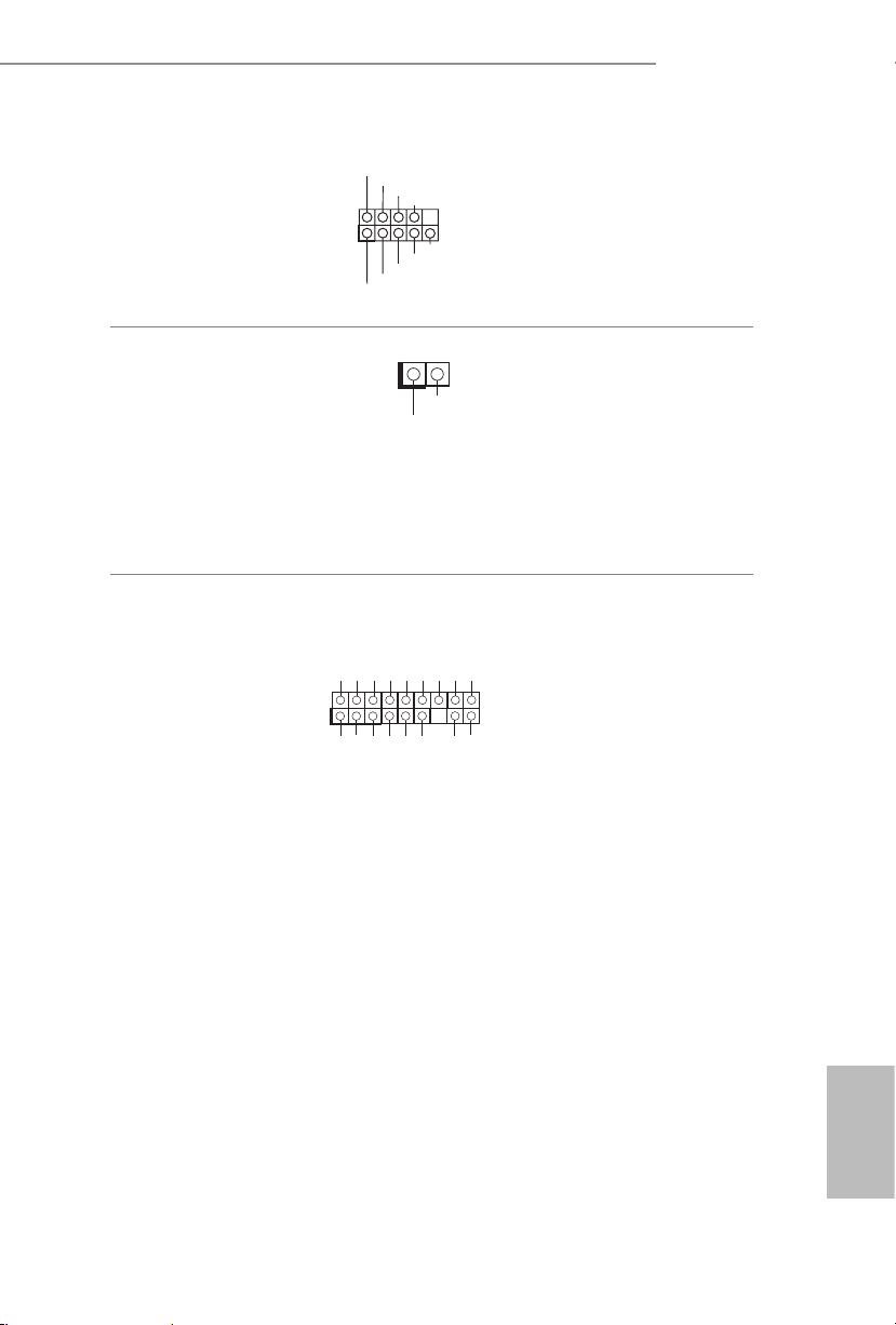
Serial Port Header
(9-p in CO M1)
(see p.10, No. 25)
is COM1 header
supports a serial port
module.
Chassis Intrusion Header
(2-pin CI1)
(see p.10, No. 24)
is motherboard
supports CASE OPEN
detection feature that
detects if the chassis cove
has been removed. is
feature requires a chassis
with chassis intrusion
detection design.
TPM Header
(17-pi n TP MS1)
(see p.10, No. 26)
is connector supports
Trusted Platform Module
(TPM) system, which can
securely store keys, digital
certicates, passwords,
and data. A TPM system
also helps enhance
network securit y, protects
digital identities, and
ensures platform integrity.
1
GN D
SMB _DA TA_ MAI N
LAD 2
LAD 1
GN D
S_P WRD WN #
SER IRQ #
GN
D
PC ICL K
PC IRS T #
LAD 3
+3 V
LAD 0
+3V S B
GN D
FRA M E
SMB _CL K_M AIN
1
Signal
GND
24
English
2.7 CrossFireXTM and Quad CrossFireXTM Operation Guide
is motherboard supports CrossFireXTM and Quad CrossFireXTM that allows you to
install up to two identical PCI Express x16 graphics cards. Currently CrossFireX
TM
and Quad CrossFireXTM are supported with Windows® 7 / 7 64-bit / 8 / 8 64-bit / 8.1
/ 8.1 64-bit OS.
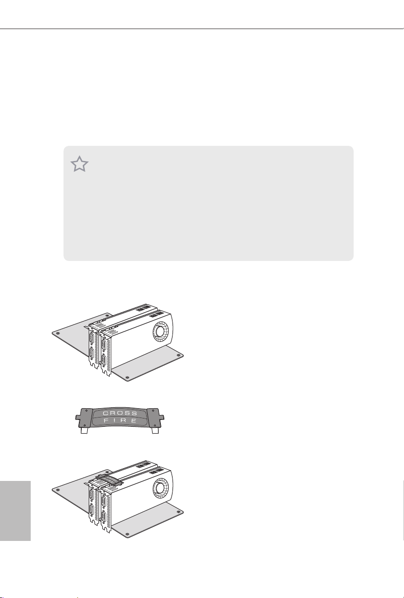
2.7.1 Installing Two CrossFireXTM-Ready Graphics Cards
Step 1
Insert one graphics card into PCIE1 slot
and the other graphics card to PCIE3 slot.
Make sure that the cards are properly
seated on the slots.
Step 2
Connect two graphics cards by installing
a CrossFire Bridge on the CrossFire Bridge
Interconnects on the top of the graphics
cards. (e CrossFire Bridge is provided
with the graphics card you purchase, not
bundled with this motherboard. Please
refer to your graphics card vendor for
deta ils .)
1. You should only use identical CrossFireXTM-ready g raphics cards that are AM D
certied.
2. Make sure that your graphics card drive r supports AMD CrossFireX
TM
technology.
Download the drivers from the A MD’s website: www.amd.com
3. Make sure that your power supply unit (PSU) can provide at lea st the minimum
power your syste m require s. It is recommended to use a AMD certied PSU. Plea se
refer to the AMD’s website for d etail s.
4. If you pair a 12-pipe CrossFireX
TM
Edition card with a 16-pipe card, both cards will
operate a s 12-pipe cards while in CrossFireX
TM
mode.
5. Dierent CrossFireX
TM
cards may require dierent method s to enable CrossFi-
reX
TM
. Please refer to A MD graphics card manuals for de tailed installation guide.
CrossFire Bridge

25
English
Z97 Pro4
Step 3
Connect a VGA cable or a DVI cable to the
monitor connector or the DVI connec-
tor of the graphics card that is inserted to
PCIE1 slot.

26
English
Step 1
Power on your computer and boot into OS.
Step 2
Remove the AMD drivers if you have any VGA drivers installed in your system.
Step 3
Install the required drivers and CATALYST Control Center then restart your
computer. Please check AMD’s website for details.
2.7.2 Driver Installation and Setup
Step 4
Double-click the AMD Catalyst Control
Center icon in the Windows® sy stem tray.
Step 5
In the le pane, click Performance and
then AMD CrossFireX
TM
. en select
Enable AMD CrossFireX and click Apply.
Select the GPU number according to your
graphics card and click Apply.
AMD Catalyst Control Center
e Catalyst Unins talle r is an optional do wnload. We recommend using this utility to
uninstall any previou sly installed Catalyst drive rs prior to installation. Ple ase check
AMD’s website for AMD driver updates.

27
English
Z97 Pro4
2.8 M.2_SSD (NGFF) Module Installation Guide
The M.2, a lso known as the Next Generation Form Factor (NGFF), is a sma ll size and
versatile c ard edge connector t hat aims to replace mPCIe a nd mSATA. The M.2_SSD
(NGFF) Socket 3 can accommodate either a M.2 SATA3 6.0 Gb/s module or a M.2 PCI
Express module up to Gen 2 x 2 (10 Gb/s). Please be noted that the M. 2_SSD (NGFF)
Socket 3 is shared with the SATA Express connector; you can only choose either the M.2_
SSD (NGFF) Socket 3 or the SATA Express connector to use.
*e M.2 _SSD (NGFF) Socket 3 supports SSD drives. Please note that the WiFi or other
non-SSD M.2 modules are not supported.
Installing the M.2_SSD (NGFF) Module
Step 1
Prepare a M.2_SSD (NGFF) module
and the screw.
3
2
4
5
BCDE
A
1
Step 2
Depending on the PCB type and
length of your M.2_SSD (NGFF)
module, nd the corresponding nut
location to be used.
No. 1 2 3 4 5
Nut Location A B C D E
PCB Length 3cm 4.2cm 6cm 8cm 11cm
Module Type Typ e2230 Type 224 2 Type2 260 Ty pe 2280 Ty pe 22110

28
English
BCDE
A
Step 3
Move the stando based on the
module type and length.
e stando is placed at the nut
location D by default. Skip Step 3
and 4 and go straight to Step 5 if you
are going to use the default nut.
Otherwise, release the stando by
hand.
BCDE
A
Step 4
Peel o the yellow protective lm on
the nut to be used. Hand tighten the
stando into the desired nut location
on the motherboard.
BC
A
ABCDE
Step 5
Align and gently insert the M.2
(NGFF) SSD module into the M.2
slot. Please be aware that the M.2
(NGFF) SSD module only ts in one
orientation.
NUT1NUT2DE
Step 6
Tighten the screw with a screwdriver
to secure the module into place.
Please do not overtighten the screw
as this might damage the module.

29
English
Z97 Pro4
PCIe Interface SATA Interface
Plextor PX-AG256M6e ADATA AXNS381E-128GM-B
Plextor PX-AG512M6e ADATA A XNS381E -25 6GM-B
SanDisk SD6PP4M-128G Crucial CT120M500SSD4/120G
SanDisk SD6PP4M-256G Crucial CT240M500SSD4/240G
Samsung XP941-512G (MZHPU512HCGL) Intel SSDSCKGW080A401/80G
Kingston RBU-SNS8400S3/180GD
M.2_SSD (NGFF) Module Support List
For the latest updates of M.2_SSD (NFGG) module support list, please visit our website for
details: http://www.asrock.com

30
English
Chapter 3 Software and Utilities Operation
3.1 Installing Drivers
e Support CD that comes with the motherboard contains necessary drivers and
useful utilities that enhance the motherboard’s features.
Running The Support CD
To begin using the support CD, insert the CD into your CD-ROM drive. e CD
automatically displays the Main Menu if “AUTORUN” is enabled in your computer.
If the Main Menu does not appear automatically, locate and double click on the le
“ASRSETUP.EXE” in the Support CD to display the menu.
Drivers Menu
e drivers compatible to your system will be auto-detected and listed on the
support CD driver page. Please click Install All or follow the order from top to
bottom to install those required drivers. erefore, the drivers you install can work
properly.
Utilities Menu
e Utilities Menu shows the application soware that the motherboard supports.
Click on a specic item then follow the installation wizard to install it.
To improve Windows 7 compatibility, please download and install the following hot x
provided by Microso.
“KB2720599”: http://support.microso.com/kb/2720599/en-us

31
English
Z97 Pro4
3.2 A-Tuning
A-Tuning is ASRock’s multi purpose soware suite with a new interface, more new
features and improved utilities, including XFast R AM, Dehumidier, Good Night
LED, FAN-Tastic Tuning, OC Tweaker and a whole lot more.
3.2.1 Installing A-Tuning
When you install the all-in-one driver to your system from ASRock’s support CD,
A-Tu n in g will be auto-installed as well. Aer the installation, you will nd the icon
“A- Tun i ng “ on your desktop. Double-click the “A-Tu ni n g“ icon, A -Tun i ng
main menu will pop up.
3.2.2 Using A-Tuning
ere are six sections in A-Tuning main menu: Operation Mode, Tools, OC
Tweaker, System Info, Live Update, Tech Service and Settings.
Operation Mode
Choose an operation mode for your computer.

32
English
Tool s
Various tools and utilities.
XFast RAM
Boost the system’s performance and extend the HDD’s or SDD’s lifespan! Create a
hidden partition, then assign which les should be stored in the RAM drive.
XFast LAN
Boost the speed of your internet connection! Select a specic mode for making the
designated program's priority highest.
Fast Boot
Fast Boot minimizes your computer's boot time. Please note that Ultra Fast mode
is only supported by Windows 8.1/8 and the VBIOS must support UEFI GOP if you
are using an external graphics card.
OMG
Schedule the starting and ending hours of Internet access granted to other users.
Place X marks on the time table to disable the Internet.
Good Night LED
Switch o the Power/HDD LEDs when the system is on, and automatically switch
o the Power and Keyboard LEDs when the system enters into Standby/Hibernation
mode.

33
English
Z97 Pro4
FAN-Tastic Tuning
Congure up to ve dierent fan speeds using the graph. e fans will automatically
shi to the next speed level when the assigned temperature is met.
Dehumidier
Prevent motherboard damages due to dampness. Enable this function and
congure the period of time until the computer powers on, and the duration of the
dehumidifying process.
USB Key
Plug in the USB Key and let your computer log in to windows automatically!
OC DNA
OC DNA is an unique soware which helps to save your OC settings as a prole.
en you can send this OC setting prole to the friends.
Disk Health Report
Disk Health Report is a hard disk health monitoring utilit y that displays detailed
HDD information, such as hard disk model, serial number, rmware, power on
count, power on hours, S.M.A.R.T. values, current temperature, etc. HDD, SSD
and optical disk drives are all supported. e health status block displays Good
(in green color), Caution (in yellow color) or Bad (in red color). Click on the health
status icon to congure settings for an alert to be triggered.

34
English
OC Tw eaker
Congurations for overclocking the system.
System Info
View information about the system.
*e System Browser tab may not appear for certain models.

35
English
Z97 Pro4
Live Update
Check for newer versions of BIOS or drivers.
Tech Ser vice
Contact Tech Service if you have problems with your computer. Please leave your
contact information along with details of the problem.

36
English
Settings
Congure ASRock A-Tuning. Click to select "Auto run at Windows Startup" if you
want A-Tuning to be launched when you start up the Windows operating system.

37
English
Z97 Pro4
3.3 Intel® Rapid Start Technology
Intel® Rapid Start Technolog y enables your system to wake up faster from deep
sleep, saving time and power consumption. Feel secure to know that your system
will resume to working condition even if an unexpected power loss happens while
the PC is in sleep mode.
3.3.1 System Requirements
•Conrm whether your motherboard supports this feature.
•Operating system: Microso Windows 8.1/8/7 (32- or 64-bit edition)
•Set the SATA mode to AHCI. If Windows 8.1/8/7 is already installed under
IDE mode, directly changing the SATA mode to AHCI may cause Windows
8.1/8/7 to crash while booting. If your system is not in AHCI mode, please
follow the instructions below.
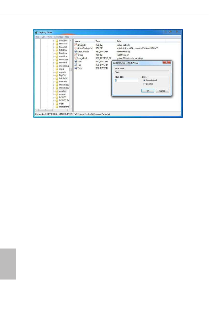
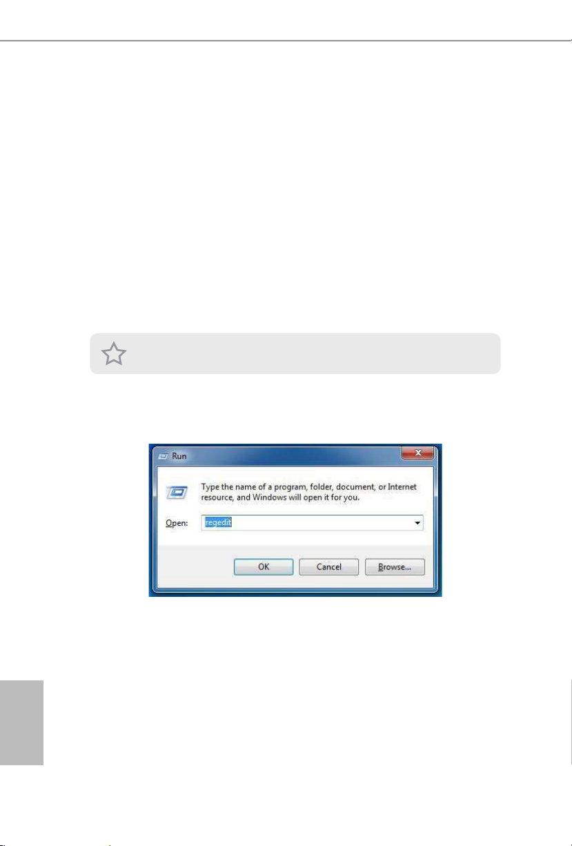
1. Press Win + R simultaneously in Windows 8.1/8/7, type "Regedit" into the
word box then click OK.
2. Enter into HKEY_LOCAL_MACHINE\SYSTEM\CurrentControlSet\services\
msahci in Windows Registry Editor. Double click on the value Start and
change the value from 3 into 0. Click on OK.
ere are certain risks. Please back up any importa nt data before operating to avoid loss.
38
English
3. Exit the Registry Editor window and restart the computer.
4. Press F2 to enter BIOS, then go to Advanced > Storage Conguration and
change SATA Mode to AHCI. Press F10 to save changes and exit.
5. Enter Windows 8.1/8/7. Windows will discover the new device and install
AHCI drivers automatically.
3.3.2 Setup Guide
Conguring Rapid Start
Step 1
Run ASRock Rapid Start utility from Start -> All Programs -> ASRock Utilit y.
Step 2
If you have more than one hard drives in your system, you must select one, then
choose the Partition Size desired for your hidden partition and click on Create. e
system will automatically create a hidden partition according to your settings. If
there are SSD’s installed into your system, it is recommended to create the partition
on the SSD.

39
English
Z97 Pro4
Step 3
When prompted to restart aer the setup, click Ye s to reboot.
Step 4
Double-click the Intel® Rapid Start Technology Manager icon in the Windows
sy stem tray.

40
English
Step 5
Make sure Rapid Start is on. Drag the slider to congure the time. For example, if
the timer value is set to ten minutes, the system will enable Rapid Start mode aer
entering sleep state for ten minutes. If the timer is set to 0 minutes, Windows will
immediately enable Rapid Start mode as it enters sleep state.
Using Rapid Start
1. You may shut down the computer without terminating the applications or les
you are executing currently. Click on Windows Start > the arrow next to Shut
down, and click on Sleep.
2. Windows system will enter sleep state.
3. According to your settings in Rapid Start Technology Manager, the system
will automatically wake up and enable Rapid Start mode aer entering sleep

41
English
Z97 Pro4
state for a period of time. e power of the computer in Rapid Start mode can
be cut o, it will not cause data loss of the programs or les you were executing
before entering sleep state.
4. When you wish to continue to use the computer just hit the power button, the
system will rapidly return to Windows, the programs and les which you were
using before entering sleep state will be accessible immediately.
42
English
3.4 Intel® Smart Connect Technology
Intel® Smart Connect Technology is a feature that periodically wakes your computer
from Windows® sleep state to refresh email or social networking applications. It
saves your waiting time and keeps the content always up-to-date.
3.4.1 System Requirements
•Conrm whether your motherboard supports this feature.
•Operating system: Microso Windows 8/7 (32- or 64-bit edition)
•Set the SATA mode to AHCI. If Windows 8/7 is already installed under IDE
mode, directly changing the SATA mode to AHCI may cause Windows 8/7
to crash while booting. If your system is not in AHCI mode, please follow the
instructions below.
1. Press Win + R simultaneously in Windows 8/7, type "Regedit" into the word
box then click OK.
2. Enter into HKEY_LOCAL_MACHINE\SYSTEM\CurrentControlSet\services\
msahci in Windows Registry Editor. Double click on the value Start and
change the value from 3 into 0. Click on OK.
ere are certain risks. Please back up any importa nt data before operating to avoid loss.

43
English
Z97 Pro4
3.4.2 Setup Guide
Installing ASRock Smart Connect Utility
Step 1
Install ASRock Smart Connect Utility, which is located in the folder at the following
path of the Support CD: \ ASRock Utility > Smart Connect.
Step 2
Once installed, run ASRock Smart Connect from your desktop or go to Windows
Start -> All Programs -> ASRock Utility.

44
English
Step 3
Click the Add button. Take Foxmail as an example, add Foxmail to the Application
list.
Step 4
Select Foxmail from the Application List, then click the arrow pointing right to add
this application to the Smart Connect List.
Step 5
Click Apply to enable Smart Connect.
45
English
Z97 Pro4
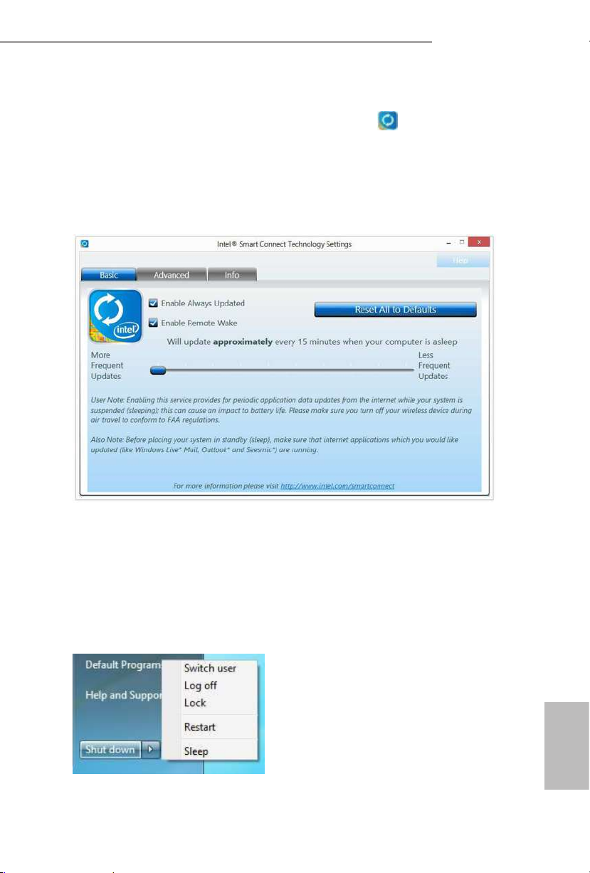
Step 6
Double-click the Intel® Smart Connect Technology Manager icon in the
Windows system tray.
Step 7
Drag the slider to congure how oen the system will connect to the network to
download updates. Shorter durations will provide more frequent updates, but may
cause more power consumption.
Using Smart Connect
1. Keep the applications which you wish to connect to the internet and receive
updates while the system is in sleep state running. Foxmail for instance, keep
Foxmail running.
2. Click on Windows Start -> the arrow next to Shut down, and click on Sleep.
3. Windows system will enter sleep state.

46
English
4. e system will wake up from sleep state periodically, and then start to update
Foxmail. e screen will not display anything so the computer can maintain
minimum power usage. Aerwards, the system will automatically return to
sleep state again.
5. Upon waking up the system, you will nd the new mail that were sent to you
during sleep state are already updated and ready to be read in Foxmail.
47
English
Z97 Pro4
3.5 ASRock APP Shop
e ASRock APP Shop is an online store for purchasing and downloading soware
applications for your ASRock computer. You can install various apps and support
utilities quickly and easily, and optimize your system and keep your motherboard
up to date simply with a few clicks.
Double-click
on your desktop to access ASRock APP Shop utility.
*You need to be connected to the Internet to download apps f rom the ASRock APP Shop.
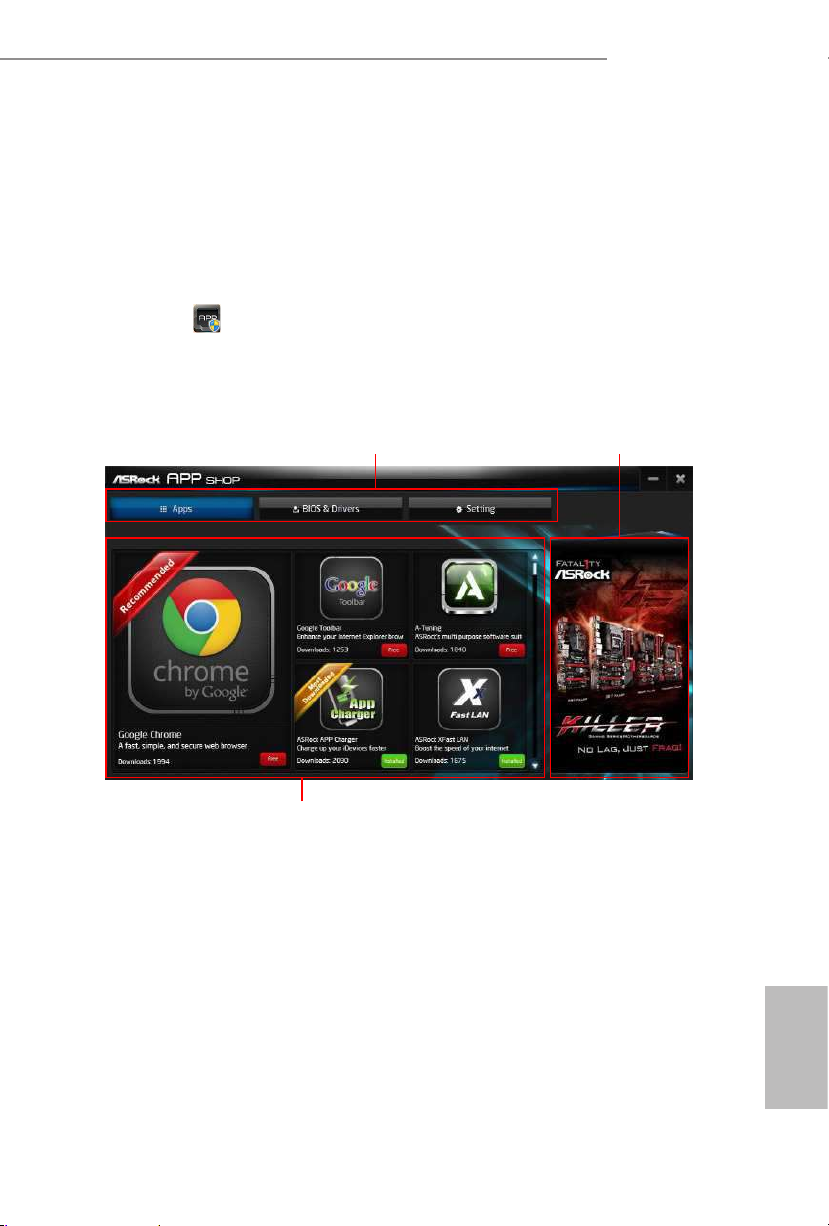
3.5.1 UI Overview
Category Panel: e category panel contains several category tabs or buttons that
when selected the information panel below displays the relative information.
Information Panel: e information panel in the center displays data about the
currently selected category and allows users to perform job-related tasks.
Hot News: e hot news section displays the various latest news. Click on the image
to visit the website of the selected news and know more.
Information Panel
Hot News
Category Panel

48
English
3.5.2 Apps
When the "Apps" tab is selected, you will see all the available apps on screen for you
to download.
Installing an App
Step 1
Find the app you want to install.
e most recommended app appears on the le side of the screen. e other various
apps are shown on the right. Please scroll up and down to see more apps listed.
You can check the price of the app and whether you have already intalled it or not.
- e red icon displays the price or "Free" if the app is free of charge.
- e green "Installed" icon means the app is installed on your computer.
Step 2
Click on the app icon to see more details about the selected app.

49
English
Z97 Pro4
Step 3
If you want to install the app, click on the red icon
to start downloading.
Step 4
When installation completes, you can nd the green "Installed " icon appears on the
upper right corner.
To uninstall it, simply click on the trash can icon .
*e trash icon may not appear for certain apps.

50
English
Upgrading an App
You can only upgrade the apps you have already installed. When there is an
available new version for your app, you will nd the mark of "New Version"
appears below the installed app icon.
Step 1
Click on the app icon to see more details.
Step 2
Click on the yellow icon
to start upgrading.

51
English
Z97 Pro4
3.5.3 BIOS & Drivers
Installing BIOS or Drivers
When the "BIOS & Drivers" tab is selected, you will see a list of recommended or
critical updates for the BIOS or drivers. Please update them all soon.
Step 1
Please check the item information before update. Click on
to see more details.
Step 2
Click to select one or more items you want to update.
Step 3
Click Update to start the update process.

52
English
3.5.4 Setting
In the "Setting" page, you can change the language, select the server location, and
determine if you want to automatically run the ASRock APP Shop on Windows
startup.

53
English
Z97 Pro4
3.6 Start8
For those Windows 8 users who miss the Start Menu, Start8 is an ideal solution that
brings back the familiar Start Menu along with added customizations for greater
eciency.
3.6.1 Installing Start8
Install Star t8, which is located in the folder at the following path of the Support CD:
\ ASRock Uti lity > Start8.
3.6.2 Conguring Start8
Style
Select between the Windows 7 style and Windows 8 style Start Menu. en select
the theme of the Start Menu and customize the style of the Start icon.

54
English
Congure
Congure provides conguration options, including icon sizes, which shortcuts you
want Start Menu to display, quick access to recently used apps, the functionality of
the power button, and more.
Control

55
English
Z97 Pro4
Control lets you congure what a click on the start button or a press on the
Windows key does.
Desktop
Desktop a llows you to disable the hot corners when you are working on the desktop.
It also lets you choose whether or not the system boots directly into desktop mode
and bypass the Metro user interface.
About
Displays information about Start8.

56
English
Chapter 4 UEFI SETUP UTILITY
4.1 Introduction
is section explains how to use the UEFI SETUP UTILITY to congure your
system. You may run the UEFI SETUP UTILITY by pressing <F2> or <Del> right
aer you power on the computer, other wise, the Power-On-Self-Test (POST) will
continue with its test routines. If you wish to enter the UEFI SETUP UTILITY aer
POST, restart the system by pressing <Ctl> + <Alt> + <Delete>, or by pressing the
reset button on the system chassis. You may also restart by turning the system o
and then back on.
4.1.1 UEFI Menu Bar
e top of the screen has a menu bar with the following selections:
Main
For setting system time/date information
OC Tweaker
For overclocking congurations
Advanced
For advanced system congurations
Tool
Useful tools
H/W Monitor
Displays current hardware status
Boot
For conguring boot settings and boot priority
Security
For security settings
Exit
Exit the current screen or the UEFI Setup Utility
Becau se the UEFI soware is constantly being upd ated, the following UEFI setup screens
and descriptions are for reference pur pose only, and they may not exactly match what you
see on your screen.

57
English
Z97 Pro4
4.1.2 Navigation Keys
Use < > key or < > key to choose among the selections on the menu bar, and
use < > key or < > key to move the cursor up or down to select items, then
press <Enter> to get into the sub screen. You can also use the mouse to click your
required item.
Please check the following table for the descriptions of each navigation key.
Navigation Key(s) Description
+ / -
To change option for the selected items
<Ta b>
Switch to next function
<PGUP>
Go to the previous page
<PGDN>
Go to the next page
<HOME>
Go to the top of the screen
<END>
Go to the bottom of the screen
<F1>
To display the General Help Screen
<F7>
Discard changes and exit the SETUP UTILITY
<F9>
Load optimal default values for all the settings
<F10>
Save changes and exit the SETUP UTILITY
<F 12>
Print screen
<ESC>
Jump to the Exit Screen or exit the current screen

58
English
4.2 Main Screen
When you enter the UEFI SETUP UTILITY, the Main screen will appear and
display the system overview.
Favorite
Display your collection of BIOS items. Press F5 to add/remove your favorite items.
Active Page on Entry
Select the default page when entering the UEFI setup utility.
Full HD UEFI
When [Auto] is selected, the resolution will be set to 1920 x 1080 if the monitor
supports Full HD resolution. If the monitor does not support Full HD resolution,
then the resolution will be set to 1024 x 768. When [Disable] is selected, the
resolution will be set to 1024 x 768 directly.
UEFI Guide
UEFI Guide is a quick tutorial for ASRock 's UEFI setup Utility. You may abort the
tutorial by pressing "
Esc
".

59
English
Z97 Pro4
4.3 OC Tweaker Screen
In the OC Tweaker screen, you can set up overclocking features.
Advanced Turbo
You can use this option to increase your system performance. is option appears only
when your CPU supports this function. is option appears only when you adopt K-Series
CPU.
Load Optimized CPU OC Setting
You can use this option to load optimized CPU overclocking setting. Please note that
overclocking may cause damage to your CPU and motherboard. It should be done at your
own risk and expense. is option appears only when you adopt K-Series CPU.
Load Optimized GPU OC Setting
You can use this option to load optimized GPU overclocking setting. Please note that
overclocking may cause damage to your GPU and motherboard. It should be done at your
own risk and expense. is option appears only when you adopt K-Series CPU.
Becau se the UEFI soware is constantly being upd ated, the following UEFI setup screens
and descriptions are for reference pur pose only, and they may not exactly match what you
see on your screen.

60
English
CPU Conguration
CPU Ratio
e CPU speed is determined by the CPU Ratio multiplied with the BCLK.
Increasing the CPU Ratio will increase the internal CPU clock speed without
aecting the clock speed of other components.
CPU Cache Ratio
e CPU Internal Bus Speed Ratio. e maximum should be the same as the CPU
Ratio.
BCLK/PCIE Frequency
e CPU speed is determined by the CPU Ratio multiplied with the BCLK.
Increasing the BCLK will increase the internal CPU clock speed but also aect the
clock speed of other components.
Spread Spectrum
Enable Spread Spectrum to reduce electromagnetic interference for passing EMI
tests. Disable to achieve higher clock speeds when overclocking.
CPU OC Fixed Mode
CPU OC x mode allows you to keep the max CPU ratio as your setting without
throttling. Please note that overclocking may cause damage to your CPU and
motherboard. It should be done at your own risk and expense.
Intel SpeedStep Technology
Intel SpeedStep technology allows processors to switch between multiple frequen-
cies and voltage points for better power saving and heat dissipation.
Intel Turbo Boost Technology
Intel Turbo Boost Technolog y enables the processor to run above its base operating
frequency when the operating system requests the highest performance state.
Filter PLL Frequency
CPU BCLK Filter Frequency. Choose 1.6 for better overclocking capabilities.
Long Duration Power Limit
Congure Package Power Limit 1 in watts. When the limit is exceeded, the CPU
ratio will be lowered aer a period of time. A lower limit can protect the CPU and
save power, while a higher limit may improve performance.

61
English
Z97 Pro4
Long Duration Maintained
Congure the period of time until the CPU ratio is lowered when the Long
Duration Power Limit is exceeded.
Short Duration Power Limit
Congure Package Power Limit 2 in watts. When the limit is exceeded, the CPU
ratio will be lowered immediately. A lower limit can protect the CPU and save
power, while a higher limit may improve performance.
Primary Plane Current Limit
Congure the current limit of the CPU under Turbo Mode in ampere. A lower
limit can protect the CPU and save power, while a higher limit may improve
performance.
GT Frequency
Congure the frequency of the integrated GPU.
GT Voltage Mode
Auto: For optimized settings.
Adaptive: Add voltage to the integrated GPU when the system is under heavy load.
Override: e voltage is xed.
GT Adaptive Voltage
Congure the voltage added to the integrated GPU when the system is under heavy
load.
GT Voltage Oset
Congure the xed voltage added to the integrated GPU.
DRAM Timing Conguration
Load XMP Setting
Load XMP settings to overclock the DDR3 memory and perform beyond standard
specications.
DRAM Reference Clock
Select Auto for optimized settings.

62
English
DRAM Frequency
If [Auto] is selected, the motherboard will detect the memory module(s) inserted
and assign the appropriate frequency automatically.
DRAM Performance Mode
Choose high performance mode to increase memory performance. Use default
settings for better system stability.
DRAM Conguration
DRAM Tweaker
Fine tune the DRAM settings by leaving marks in checkboxes. Click OK to conrm and
apply your new settings.
CAS# Latency (tCL)
e time between sending a column address to the memory and the beginning of the data
in response.
RAS# to CAS# Delay (tRCD)
e number of clock cycles required between the opening of a row of memory and
accessing columns within it.

63
English
Z97 Pro4
Row Precharge Time (tRP)
e number of clock cycles required between the issuing of the precharge command
and opening the next row.
RAS# Active Time (tRAS)
e number of clock cycles required between a bank active command and issuing the
precharge command.
Command Rate (CR)
e delay between when a memor y chip is selected and when the rst active command can
be issued.
Write Recovery Time (tWR)
e amount of delay that must elapse aer the completion of a valid write operation,
before an active bank can be precharged.
Refresh Cycle Time (tRFC)
e number of clocks from a Refresh command until the rst Activate command to
the same rank.
RAS to RAS Delay (tRRD)
e number of clocks between two rows activated in dierent banks of the same
rank.
Write to Read Delay (tWTR)
e number of clocks between the last valid write operation and the next read
command to the same internal bank.
Read to Precharge (tRTP)
e number of clocks that are inserted between a read command to a row pre-
charge command to the same rank.
Four Activate Window (tFAW)
e time window in which four activates are allowed the same rank.
CAS Write Latency (tCWL)
Congure CAS Write Latency.
tREFI
Congure refresh cycles at an average periodic interval.

64
English
tCKE
Congure the period of time the DDR3 initiates a minimum of one refresh
command internally once it enters Self-Refresh mode.
tRDRD
Congure between module read to read delay.
tRDRDDR
Congure between module read to read delay from dierent ranks.
tRDRDDD
Use this to change DRAM tRWSR Auto/Manual settings. e default is [Auto].
tWRRD
Congure between module write to read delay.
tWRRDDR
Congure between module write to read delay from dierent ranks.
tWRRDDD
Use this to change DRAM tRRSR Auto/Manual settings. e default is [Auto].
Congure between module write to read delay from dierent DIMMs.
tWRWR
Congure between module write to write delay.
tWRWRDR
Congure between module write to write delay from dierent ranks.
tWRWRDD
Congure between module write to write delay from dierent DIMMs.
tRDWR
Congure between module read to write delay.
tRDWRDR
Congure between module read to write delay from dierent ranks.
tRDWRDD
Congure between module read to write delay from dierent DIMMs.

65
English
Z97 Pro4
RTL (CHA)
Congure round trip latency for channel A.
RTL (CHB)
Congure round trip latency for channel B.
IO-L (CHA)
Congure IO latency for channel A.
IO-L (CHB)
Congure IO latency for channel B.
ODT WR (CHA)
Congure the memory on die termination resistors' WR for channel A.
ODT WR (CHB)
Congure the memory on die termination resistors' WR for channel B.
ODT NOM (CHA)
Use this to change ODT (CHA) Auto/Manual settings. e default is [Auto].
ODT NOM (CHB)
Use this to change ODT (CHB) Auto/Manual settings. e default is [Auto].
Command Tri State
Enable for DRAM power saving.
MRC Fast Boot
Enable Memory Fast Boot to skip DRAM memory training for booting faster.
DIMM Exit Mode
Select Slow Exit to reduce power consumption, or Fast Exit for better performance.

66
English
FIVR Conguration
FIVR Switch Frequency Signature
Select whether to boost or lower the FIVR Switch Frequency.
FIVR Switch Frequency Oset
Congure the percentage of frequency boost or deduction.
Vcore Override Voltage
Add voltage to the Vcore when the system is under heavy load.
Vcore Voltage Additional Oset
Congure the dynamic Vcore voltage added to the Vcore.
CPU Cache Override Voltage
Add voltage to the CPU Cache when the system is under heavy load.
CPU Cache Voltage Oset
Congure the voltage for the CPU Cache. Setting the voltage higher may increase
system stability when overclocking.
System Agent Voltage Oset
Congure the voltage for the System Agent. Setting the voltage higher may increase system
stability when overclocking.
CPU Analog IO Voltage Oset
CPU I/O Analog Voltage.
CPU Digital IO Voltage Oset
CPU I/O Digital Voltage.
CPU Integrated VR Faults
Disable FIVR Faults to raise the threshold to trigger CPU over current protection
and over voltage protection for better overclocking capabilities.
CPU Integrated VR Eciency Mode
Enable FIVR Eciency Management for power saving. Disable for better
performance and overclocking capabilities.

67
English
Z97 Pro4
Voltage Conguration
CPU Input Voltage
Congure the voltage for the CPU.
CPU Load-Line Calibration
CPU Load-Line Calibration helps prevent CPU voltage droop when the system is
under heav y load.
DRAM Voltage
Use this to congure DRAM Voltage.
PCH 1.05V Voltage
Chipset 1.05V Voltage. Use default settings for best performance.
PCH 1.5V Voltage
I/O 1.5V Voltage. Use default settings for best performance.

68
English
4.4 Advanced Screen
In this section, you may set the congurations for the following items: CPU
Conguration, Chipset Conguration, Storage Conguration, Intel® Rapid Start
Technology, Intel® Smart Connect Technology, Intel® underbolt™ , Super IO Con-
guration, ACPI Conguration, USB Conguration and Trusted Computing.
Setting wrong values in this sec tion may cause the system to malfunction.

69
English
Z97 Pro4
4.4.1 CPU Conguration
Active Processor Cores
Select the number of cores to enable in each processor package.
CPU C States Support
Enable CPU C States Support for power saving. It is recommended to keep C3, C6
and C7 all enabled for better power saving.
Enhanced Halt State (C1E)
Enable Enhanced Halt State (C1E) for lower power consumption.
CPU C3 State Support
Enable C3 sleep state for lower power consumption.
CPU C6 State Support
Enable C6 deep sleep state for lower power consumption.
CPU C7 State Support
Enable C7 deep sleep state for lower power consumption.
Package C State Support
Enable CPU, PCIe, Memory, Graphics C State Support for power saving.

70
English
CPU Thermal Throttling
Enable CPU internal thermal control mechanisms to keep the CPU from overheat-
ing.
No-Execute Memory Protection
Processors with No-Execution Memory Protection Technology may prevent certain
classes of malicious buer overow attacks.
Intel Virtualization Technology
Intel Virtualization Technology allows a platform to run multiple operating systems
and applications in independent partitions, so that one computer system can
function as multiple virtual systems.
Hardware Prefetcher
Automatically prefetch data and code for the processor. Enable for better
performance.
Adjacent Cache Line Prefetch
Automatically prefetch the subsequent cache line while retrieving the currently
requested cache line. Enable for better performance.

71
English
Z97 Pro4
4.4.2 Chipset Conguration
Primary Graphics Adapter
Select a primary VGA.
VT-d
Intel® Virtualization Technology for Directed I/O helps your virtual machine
monitor better utilize hardware by improving application compatibility and
reliability, and providing additional levels of manageability, security, isolation, and
I/O performance.
PCIE1 Link Speed
Select the link speed for PCIE1.
Share Memory
Congure the size of memory that is allocated to the integrated graphics processor
when the system boots up.
IGPU Multi-Monitor
Select disable to disable the integrated graphics when an external graphics card is
installed. Select enable to keep the integrated graphics enabled at all times.
Render Standby
Power down the render unit when the GPU is idle for lower power consumption.

72
English
Onboard HD Audio
Enable/disable onboard HD audio. Set to Auto to enable onboard HD audio and
automatically disable it when a sound card is installed.
Front Panel
Enable/disable front panel HD audio.
On/O Play
With ASRock On/O Play users can connect their portable audio devices, such
as an MP3 player or a mobile phone to the PC and listen to music through the
computer's speakers even when the computer is turned o.
Onboard HDMI HD Audio
Enable audio for the onboard digital outputs.
Onboard LAN
Enable or disable the onboard network interface controller.
Deep Sleep
Congure deep sleep mode for power saving when the computer is shut down.
Restore on AC/Power Loss
Select the power state aer a power failure. If [Power O] is selected, the power will
remain o when the power recovers. If [Power On] is selected, the system will start
to boot up when the power recovers.
Good Night LED
By enabling Good Night LED, the Power/HDD LEDs will be switched o when the
system is on. It will also automatically switch o the Power and Keyboard LEDs
when the system enters into Standby/Hibernation mode.

73
English
Z97 Pro4
4.4.3 Storage Conguration
SATA Controller(s)
Enable/disable the SATA controllers.
SATA Mode Selection
IDE: For better compatibility.
AHCI: Supports new features that improve performance.
RAID: Combine multiple disk drives into a logical unit.
SATA Aggressive Link Power Management
SATA Aggressive Link Power Management allows SATA devices to enter a low
power state during periods of inactivity to save power. It is only supported by AHCI
mode.
AHCI (Advanc ed Host Controll er Inter face) support s NCQ and other new features that
will improve SATA disk performance but IDE mod e does not have these advantages.

74
English
Dynamic Storage Accelerator
Keep this option enabled for higher HDD and SDD I/O performance, lower latency and
increased system responsiveness.
Hard Disk S.M.A.R.T.
S.M.A.R.T stands for Self-Monitoring, Analysis, and Reporting Technology. It is a
monitoring system for computer hard disk drives to detect and report on various
indicators of reliability.
M2_1/SATA3_4, SATA3_5 Switch
Auto: M2_1/SATA3_4, SATA3_5 auto switch
Force_SATA: Switch to SATA3_4, SATA3_5
Force_M2_1: Switch to M2_1

75
English
Z97 Pro4
4.4.4 Intel® Rapid Start Technology
Intel® Rapid Start Technology
Intel® Rapid Start Technolog y is a new zero power hibernation mode which allows
users to resume in just 5-6 seconds.

76
English
4.4.5 Intel® Smart Connect Technology
Intel® Smart Connect Technology
Intel® Smart Connect Technology automatically updates your email and social
networks, such as Twitter, Facebook, etc. while the computer is in sleep mode.

77
English
Z97 Pro4
4.4.6 Intel® Thunderbolt™
Intel Thunderbolt™ Technology
Enable or disable the Intel® underbolt™ function.
Security Level
Select Legacy to skip the Windows certication checking process for underbolt™
devices. Select Unique ID for checking the Windows certication, and show
warning messages if the devices aren't certied. Or select DP++ to support DP 1.2.
Wake From Thunderbolt™ Devices
Allow the system to be waked up by underbolt™ devices.
Ignore Thunderbolt™ Option Rom
Enable to skip underbolt™ Option ROM during POST for faster boot speed.
TBT Device IO resource Support
Enable IO Resource Support if your older underbolt devices have trouble working
properly.
Thunderbolt™ PCIe Cache-line Size
Congure the cache-line size of the underbolt PCIe subtree.

78
English
4.4.7 Super IO Conguration
PS2 Y- Cable
Enable the PS2 Y-Cable or set this option to Auto.
Serial Port
Enable or disable the Serial port.
Serial Port Address
Select the address of the Serial port.

79
English
Z97 Pro4
4.4.8 ACPI Conguration
Suspend to RAM
Select disable for ACPI suspend type S1. It is recommended to select auto for ACPI
S3 power saving.
Check Ready Bit
Enable to enter the operating system aer S3 only when the hard disk is ready, this
is recommended for better system stability.
ACPI HPET Table
Enable the High Precision Event Timer for better performance and to pass WHQL
tests.
PS/2 Keyboard Power On
Allow the system to be waked up by a PS/2 Keyboard.
PCI Devices Power On
Allow the system to be waked up by a PCI device and enable wake on LAN.
Wake From Onboard LAN
Allow the system to be waked up by the onboard LAN.

80
English
Ring-In Power On
Allow the system to be waked up by onboard COM port modem Ring-In signals.
RTC Alarm Power On
Allow the system to be waked up by the real time clock alarm. Set it to By OS to let
it be handled by your operating system.
USB Keyboard/Remote Power On
Allow the system to be waked up by an USB keyboard or remote controller.
USB Mouse Power On
Allow the system to be waked up by an USB mouse.

81
English
Z97 Pro4
4.4.9 USB Conguration
USB Controller
Enable or disable all the USB ports.
Intel USB 3.0 Mode
Select Intel® USB 3.0 controller mode. Set [Smart Auto] to keep the USB 3.0 driver
enabled aer rebooting (USB 3.0 is enabled in BIOS). Set [Auto] to automatically
enable the USB 3.0 driver aer entering the OS (USB 3.0 is disabled in BIOS). Set
[Enabled] to keep the USB 3.0 driver enabled (Must install driver to use USB devices
under Windows® 7). Set [Disabled] to disable the USB 3.0 ports.
Legacy USB Support
Enable or disable Legacy OS Support for USB 2.0 devices. If you encounter USB
compatibility issues it is recommended to disable legacy USB support. Select UEFI
Setup Only to support USB devices under the UEFI setup and Windows/Linux
operating systems only.
Legacy USB 3.0 Support
Enable or disable Legacy OS Support for USB 3.0 devices. If you encounter USB
compatibility issues it is recommended to disable legacy USB support. Select UEFI
Setup Only to support USB devices under the UEFI setup and Windows/Linux
operating systems only.

82
English
USB Compatibility Patch
If your USB devices (i.e. USB mouse or storage) encounter compatibility problems,
please enable this option to x it. Please note that aer enabling this option, it is
normal that the system will postpone booting up aer pressing the power button.

83
English
Z97 Pro4
4.4.10 Trusted Computing
Security Device Support
Enable or disable BIOS support for security device.

84
English
4.5 Tools
System Browser
ASRock System Browser shows the overview of your current PC and the devices
connected.
OMG (Online Management Guard)
Administrators are able to establish an internet curfew or restrict internet access
at specied times via OMG. You may schedule the starting and ending hours of
internet access granted to other users. In order to prevent users from bypassing
OMG, guest accounts without permission to modify the system time are required.
UEFI Tech Service
Contact ASRock Tech Service if you are having trouble with your PC. Please setup
network conguration before using UEFI Tech Service.
Easy RAID Installer
Easy R AID Installer helps you to copy the R AID driver from the support CD to
your USB storage device. Aer copying the drivers please change the SATA mode to
RAID, then you can start installing the operating system in RAID mode.

85
English
Z97 Pro4
Easy Driver Installer
For users that don’t have an optical disk drive to install the drivers from our support
CD, Easy Driver Installer is a handy tool in the UEFI that installs the LAN driver
to your system via an USB storage device, then downloads and installs the other
required drivers automatically.
Instant Flash
Save UEFI les in your USB storage device and run Instant Flash to update your
UEFI.
Internet Flash
ASRock Internet Flash downloads and updates the latest UEFI rmware version
from our servers for you. Please setup network conguration before using Internet
Flash.
*For BIOS backup and recovery purpose, it is recommended to plug in your USB
pen drive before using this function.
Network Conguration
Use this to congure internet connection settings for Internet Flash.
Internet Setting
Enable or disable sound eects in the setup utility.

86
English
UEFI Download Server
Select a server to download the UEFI rmware.
Dehumidier Function
If Dehumidier Function is enabled, the computer will power on automatically to
dehumidify the system aer entering S4/S5 state.
Dehumidier Period
Congure the period of time until the computer powers on and enables
Dehumidier aer entering S4/S5 state.
Dehumidier Duration
Congure the duration of the dehumidifying process before it returns to S4/S5
state.
Dehumidier CPU Fan Setting
Congure the speed of the CPU fan while Dehumidier is enabled. e higher the
value, the faster the fan speed.
Max: 255
Min: 1
Save User Default
Type a prole name and press enter to save your settings as user default.
Load User Default
Load previously saved user defaults.

87
English
Z97 Pro4
4.6 Hardware Health Event Monitoring Screen
is section allows you to monitor the status of the hardware on your system,
including the parameters of the CPU temperature, motherboard temperature, fan
speed and voltage.
CPU Fan 1 & 2 Setting
Select a fan mode for CPU Fans 1&2, or choose Customize to set 5 CPU
temperatures and assign a respective fan speed for each temperature.
Chassis Fan 1 Setting
Select a fan mode for Chassis Fan 1, or choose Customize to set 5 CPU temperatures
and assign a respective fan speed for each temperature.
Chassis Fan 2 Setting
Select a fan mode for Chassis Fan 2, or choose Customize to set 5 CPU temperatures
and assign a respective fan speed for each temperature.
Over Temperature Protection
When Over Temperature Protection is enabled, the system automatically shuts
down when the motherboard is overheated.
Case Open Feature
Enable or disable Case Open Feature to detect whether the chassis cover has been
removed.

88
English
4.7 Boot Screen
is section displays the available devices on your system for you to congure the
boot settings and the boot priority.
Fast Boot
Fast Boot minimizes your computer's boot time. In fast mode you may not boot
from an USB storage device. Ultra Fast mode is only supported by Windows 8.1/8
and the VBIOS must support UEFI GOP if you are using an external graphics card.
Please notice that Ultra Fast mode will boot so fast that the only way to enter this
UEFI Setup Utility is to Clear CMOS or run the Restart to UEFI utility in Windows.
Boot From Onboard LAN
Allow the system to be waked up by the onboard LAN.
Setup Prompt Timeout
Congure the number of seconds to wait for the setup hot key.
Bootup Num-Lock
Select whether Num Lock should be turned on or o when the system boots up.
Boot Beep
Select whether the Boot Beep should be turned on or o when the system boots up. Please
note that a buzzer is needed.

89
English
Z97 Pro4
Full Screen Logo
Enable to display the boot logo or disable to show normal POST messages.
AddOn ROM Display
Enable AddOn ROM Display to see the AddOn ROM messages or congure the
AddOn ROM if you've enabled Full Screen Logo. Disable for faster boot speed.
Boot Failure Guard
If the computer fails to boot for a number of times the system automatically restores
the default settings.
Boot Failure Guard Count
Congure the number of attempts to boot until the system automatically restores
the default settings.
CSM (Compatibility Support Module)
CSM
Enable to launch the Compatibility Support Module. Please do not disable unless
you’re running a WHCK test. If you are using Windows 8.1/8 64-bit and all of your
devices support UEFI, you may also disable CSM for faster boot speed.

90
English
Launch PXE OpROM Policy
Select UEFI only to run those that support UEFI option ROM only. Select Legacy
only to run those that support legacy option ROM only. Do not launch?
Launch Storage OpROM Policy
Select UEFI only to run those that support UEFI option ROM only. Select Legacy
only to run those that support legacy option ROM only. Do not launch?
Launch Video OpROM Policy
Select UEFI only to run those that support UEFI option ROM only. Select Legacy
only to run those that support legacy option ROM only. Do not launch?
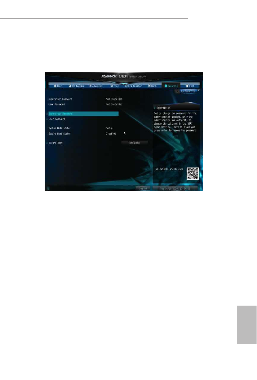
91
English
Z97 Pro4
4.8 Security Screen
In this section you may set or change the supervisor/user password for the system.
You may also clear the user password.
Supervisor Password
Set or change the password for the administrator account. Only the administrator
has authority to change the settings in the UEFI Setup Utility. Leave it blank and
press enter to remove the password.
User Password
Set or change the password for the user account. Users are unable to change the
settings in the UEFI Setup Utility. Leave it blank and press enter to remove the
password.
Secure Boot
Enable to support Windows 8.1 / 8 Secure Boot.

92
English
4.9 Exit Screen
Save Changes and Exit
When you select this option the following message, “Save conguration changes
and exit setup?” will pop out. Select [OK] to save changes and exit the UEFI SETUP
UTILITY.
Discard Changes and Exit
When you select this option the following message, “Discard changes and exit
setup?” will pop out. Select [OK] to exit the UEFI SETUP UTILITY without saving
any changes.
Discard Changes
When you select this option the following message, “Discard changes?” will pop
out. Select [OK] to discard all changes.
Load UEFI Defaults
Load UEFI default values for a ll options. e F9 key can be used for this operation.
Launch EFI Shell from lesystem device
Copy shellx64.e to the root directory to launch EFI Shell.

93
English
Z97 Pro4
Contact Information
If you need to contact ASRock or want to know more about ASRock, you’re welcome
to visit ASRock’s website at http://ww w.asrock.com; or you may contact your dealer
for further information. For technical questions, please submit a support request
form at http://www.asrock.com/support/tsd.asp
ASRock Incorporation
2F., No.37, Sec. 2, Jhongyang S. Rd., Beitou District,
Taipei City 112, Taiwan (R.O.C.)
ASRock EUROPE B.V.
Bijsterhuizen 3151
6604 LV Wijchen
e Netherlands
Phone: +31-24-345-44-33
Fax: +31-24-345-44-38
ASRock America, Inc.
13848 Magnolia Ave, Chino, CA91710
U.S.A.
Phone: +1-909-590-8308
Fax: +1-909-590-1026
 Loading...