

Page 1

Vision 3D Series
User Manual
Version 1.0
Published July 2011
Copyright©2011 ASRock INC. All rights reserved.
1
Page 2

Copyright Notice:
No part of this manual may be reproduced, transcribed, transmitted, or translated in
any language, in any form or by any means, except duplication of documentation by
the purchaser for backup purpose, without written consent of ASRock Inc.
Products and corporate names appearing in this manual may or may not be registered trademarks or copyrights of their respective companies, and are used only for
identifi cation or explanation and to the owners’ benefi t, without intent to infringe.
Disclaimer:
Specifi cations and information contained in this manual are furnished for informa-
tional use only and subject to change without notice, and should not be constructed
as a commitment by ASRock. ASRock assumes no responsibility for any errors or
omissions that may appear in this manual.
With respect to the contents of this manual, ASRock does not provide warranty of
any kind, either expressed or implied, including but not limited to the implied warranties or conditions of merchantability or fi tness for a particular purpose.
In no event shall ASRock, its directors, offi cers, employees, or agents be liable for
any indirect, special, incidental, or consequential damages (including damages for
loss of profi ts, loss of business, loss of data, interruption of business and the like),
even if ASRock has been advised of the possibility of such damages arising from
any defect or error in the manual or product.
This device complies with Part 15 of the FCC Rules. Operation is subject to the following two conditions:
(1) this device may not cause harmful interference, and
(2) this device must accept any interference received, including interference that
may cause undesired operation.
CALIFORNIA, USA ONLY
The Lithium battery adopted on this product contains Perchlorate, a toxic
substance controlled in Perchlorate Best Management Practices (BMP) regulations
passed by the California Legislature. When you discard the Lithium battery in California, USA, please follow the related regulations in advance.
“Perchlorate Material-special handling may apply, see
www.dtsc.ca.gov/hazardouswaste/perchlorate”
ASRock Website: http://www.asrock.com
2
Page 3

Safety instructions
Your system is designed and tested to meet the latest standards of safety for information technology equipment. However, to ensure your safety, it is important that
you read the fol lowing safety instructions.
Setting up your system
• Read and follow all instructions in the documentation before you operate
your system.
• Do not use this product near water or a heated source such as a radiator.
• Set up the system on a stable surface.
• Openings on the chassis are for ventilation. Do not block or cover these
openings. Make sure you leave plenty of space around the system for
ventilation. Never insert objects of any kind into the ventilation openings.
• Use this product in environments with ambient temperatures between 0o C
and 40o C.
• If you use an extension cord, make sure that the total ampere rating of the
devices plugged into the extension cord does not exceed its ampere rating.
Care during use
• Do not walk on the power cord or allow anything to rest on it.
• Do not spill water or any other liquids on your system.
• When the system is turned OFF, a small amount of electrical current still
fl ows. Always unplug all power, modem, and network cables from the
power outlets before cleaning the system.
• If you encounter the following technical problems with the product, unplug
the power cord and contact a qualifi ed service technician or your retailer.
• The power cord or plug is damaged.
• Liquid has been spilled into the system.
• The system does not function properly even if you follow the operating
instructions.
• The system was dropped or the cabinet is damaged.
• The system performance changes.
No disassembly
NOTE:
The warranty does not apply to products (including HDD, ODD, memory
and warranty seal) that have been damaged as a result of attempting to
disassemble/reassemble the system or modifying the hardware
confi guration.
3
Page 4
Safety cautions and warnings
Optical Drive Safety Information
Optical drives sold with this system contains a CLASS 1 LASER PRODUCT.
CAUTION:
Invisible laser radiation when open. Do not stare into beam or view
directly with optical instruments.
WARNING:
Making adjustments or performing procedures other than those specifi ed
in the user’s manual may result in hazardous laser exposure. Do not
attempt to disassemble the optical drive. For your safety, have the optical
drive serviced only by an authorized service provider.
Product disposal notice
IMPORTANT:
This symbol of the crossed out wheeled bin indicates that the product
(elec trical and electronic equipment) should not be placed in municipal
waste. Check local regu lations for disposal of electronic products.
Nordic Lithium Cautions (for lithium-ion batteries)
CAUTION!
Danger of explosion if battery is incorrectly replaced. Replace only with
the same or equivalent type recommended by the manufacturer. Dispose
of used batteries ac cording to the manufacturer’s instructions.
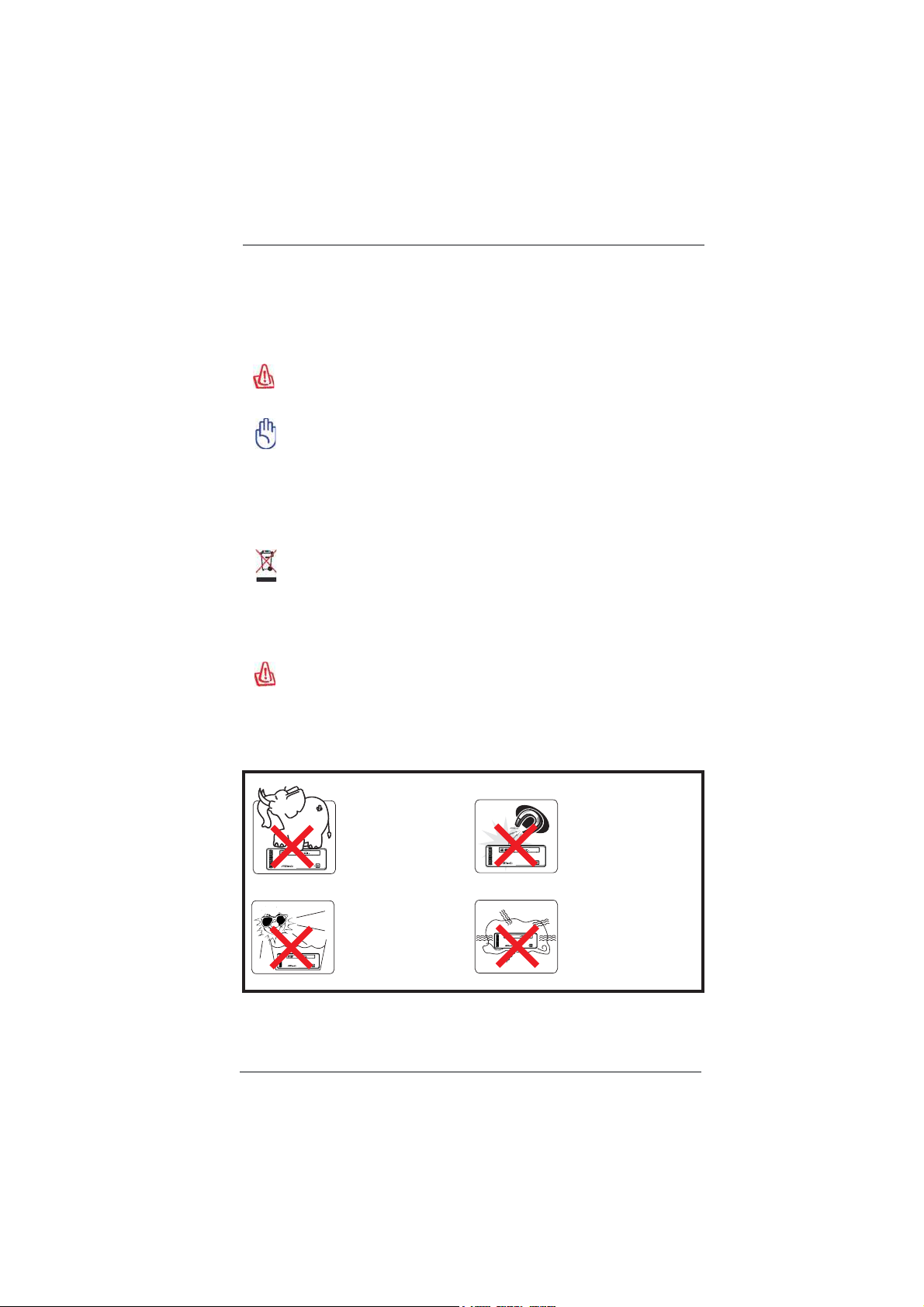
Installation Notices
4
Do not place this
product underneath
heavy loads or in an
unstable position.
Do not expose this
product to high levels
of direct sunlight,
high-humidity or wet
conditions.
Do not use or expose this
product around magnetic
fi elds as magnetic
interference may affect
the performance of the
product.
Do not block the air
vents to this product or
impede the airfl ow in any
way.
Page 5

Contents
1 Introduction ......................................................... 7
1.1 Package Contents ......................................................... 7
1.2 Specifi cations ................................................................. 8
1.3 System Motherboard Components ................................ 9
1.4 Rear Panel Connections .............................................. 11
1.5 System Chassis ........................................................... 12
1.6 Remote Controller ........................................................ 13
2 Opening the chassis ........................................... 14
3 Reinstalling the ODD/HDD ................................... 15
4 Reinstalling the DIMMs ........................................ 16
5 Reinstalling the CPU ............................................ 17
6 Reinstalling the MXM card .................................. 18
7 Driver Installation ................................................. 19
8 UTILITY MEMU ........................................................ 20
8.1 Instant Boot .................................................................... 20
8.1.1 Introduction .......................................................... 20
8.1.2 Installation ............................................................ 21
8.2 ASRock Extreme Tuning Utility (AXTU) ......................... 23
8.2.1 Introduction .......................................................... 23
8.2.2 Installation ............................................................ 23
8.2.3 Function ............................................................... 23
8.3 CyberLink DVD Suite free bundle (Trial version,
including PowerDVD, PowerDirector, etc) ..................... 26
8.4 CyberLink PowerDVD 10 Blu-ray 3D OEM version ....... 28
8.5 Symantec Norton AntiVirus Software free bundle
(Trial version) ................................................................. 29
8.6 THX TruStudio Software free bundle ............................. 30
8.7 The best Apple charge companion - ASRock APP
Charger .......................................................................... 31
8.8 Lucid Virtu ...................................................................... 32
8.9 CyberLink MediaEspresso 6.5 (Trial version) ................ 40
8.10 ASRock MAGIX Multimedia Suite - Exclusive
download software for ASRock cuntomers .................... 41
8.11 ASRock XFast USB Technology - Faster Than Your
Imagination! ................................................................... 42
8.12 ASRock XFast LAN - Faster Internet Access ................. 45
5
Page 6

9 UEFI SETUP UTILITY ................................................. 46
9.1 Introduction .................................................................... 46
9.1.1 UEFI Menu Bar .................................................... 46
9.1.2 Navigation Keys ................................................... 47
9.2 Main Screen ................................................................... 47
9.3 OC Tweaker Screen ...................................................... 48
9.4 Advanced Screen ........................................................... 51
9.4.1 CPU Confi guration ............................................... 52
9.4.2 North Bridge Confi guration................................... 54
9.4.3 South Bridge Confi guration .................................. 55
9.4.4 Storage Confi guration .......................................... 57
9.4.5 Super IO Confi guration ........................................ 58
9.4.6 ACPI Confi guration............................................... 59
9.4.7 USB Confi guration ............................................... 60
9.5 Hardware Health Event Monitoring Screen ................... 61
9.6 Boot Screen ................................................................... 62
9.7 Security Screen ............................................................. 63
9.8 Exit Screen .................................................................... 64
10 Software Support ............................................... 65
10.1 Install Operating System ................................................ 65
10.2 Support CD Information ................................................. 65
10.2.1 Running Support CD .......................................... 65
10.2.2 Drivers Menu ...................................................... 65
10.2.3 Utilities Menu...................................................... 65
10.2.4 Contact Information ............................................ 65
6
Page 7

Chapter 1 Introduction
Thank you for purchasing ASRock Vision 3D Series, a reliable product
produced under ASRock’s consistently stringent quality control. It delivers excellent
performance with robust design conforming to ASRock’s commitment to quality and
endurance.
In this manual, chapter 1 and 2 contain introduction of the hardware and step-bystep guide to the hardware installation. Chapter 3 and 4 contain the confi guration
guide to BIOS setup and information of the Support CD.
Because the hardware specifi cations and the BIOS software might be
updated, the content of this manual will be subject to change without notice. In case any modifi cations of this manual occur, the updated version
will be available on ASRock website without further notice. You may fi nd
the latest VGA cards and CPU support lists on ASRock website as well.
ASRock website http://www.asrock.com
If you require technical support related to this product, please visit our
website for specifi c information about the model you are using.
www.asrock.com/support/index.asp
1.1 Package Contents
ASRock Vision 3D Series ASRock Support CD ASRock Quick Start Guide
One AC Power Cord One AC/DC Adapter One DVI to D-Sub Adapter
Remote Controller SATA and Power Cables 3.5mm Audio Cable
7
Page 8

1.2 Specifications
* For barebone system, it may not contain CPU, memory, HDD or ODD.
Processor Intel® Mobile Sandy Bridge Processor, supports 2nd
Generation Intel
Bridge Processor Family
Chipset Mobile Intel
Memory Supports DDR3 1600*1/1333/1066MHz, 2xSO-DIMM slots ,
maximun up to 16GB
Display NVIDIA
®
GeForce GT540M Graphics,
NVIDIA® 3D Vision capable
HDD Support 2.5” SATA HDD
ODD BD Combo or DVD Super Multi
Front I/O 2 x USB 3.0, 1 x MIC, 1 x Head phone,
4-in-1 Card reader (MMC/SD/MS/MS Pro)
Rear I/O 1 x HDMI, 1 x DVI-I (Dual-Link), 4 x USB 2.0, 1 x S/PDIF,
1 x eSATA3
Audio 7.1 Ch HD Audio with THX TruStudio
LAN Gigabit LAN
WiFi 802.11b/g/n wireless LAN (300Mbps)
Remote Support MCE function
Controller
Power 90W/19V Adapter
Dimension 200mm(W)x70mm(H)x200m(L)
Volume (liters) 2.8L
*1
Supports DDR3 1600MHz depends on CPU type. (eg. Core i5 series or above CPU.)
*2
For eSATA function, Hot Plug function is supported in AHCI mode only. IDE mode does
not support Hot Plug function.
®
Corei7/i5/i3 Dual-Core Mobile Sandy
®
HM65 chipset
*2
, 2 x USB3.0
TM
WARNING
Please realize that there is a certain risk involved with overclocking, including
adjusting the setting in the BIOS, or using the third-party overclocking tools.
Overclocking may affect your system stability, or even cause damage to the
components and devices of your system. It should be done at your own risk and
expense. We are not responsible for possible damage caused by overclocking.
8
Page 9
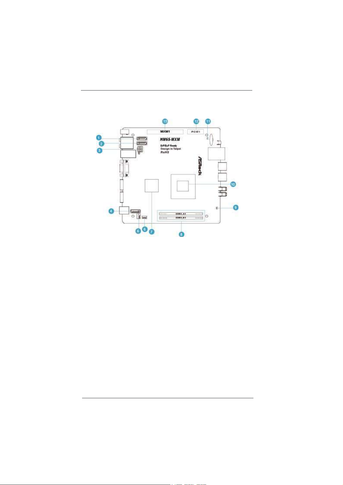
1.3 System Motherboard Components
1. SATA connector: For HDD SATA data cable
2. SATA 3.0 connector: For HDD SATA data cable
3. ATX5V output power connector for slim ODD & 2.5” HDD
4. SATA connector: For ODD SATA data cable
5. SATA power cable connector (+5V/+12V) for second HDD
6. Fan connector
7. HM65 PCH chipset
8. Memory socket
9. Infrared module header
10. CPU
11. Clear CMOS jumper
12. Mini-PCI Express expansion slot: For WiFi module
13. MXM 3.0 slot
9
Page 10
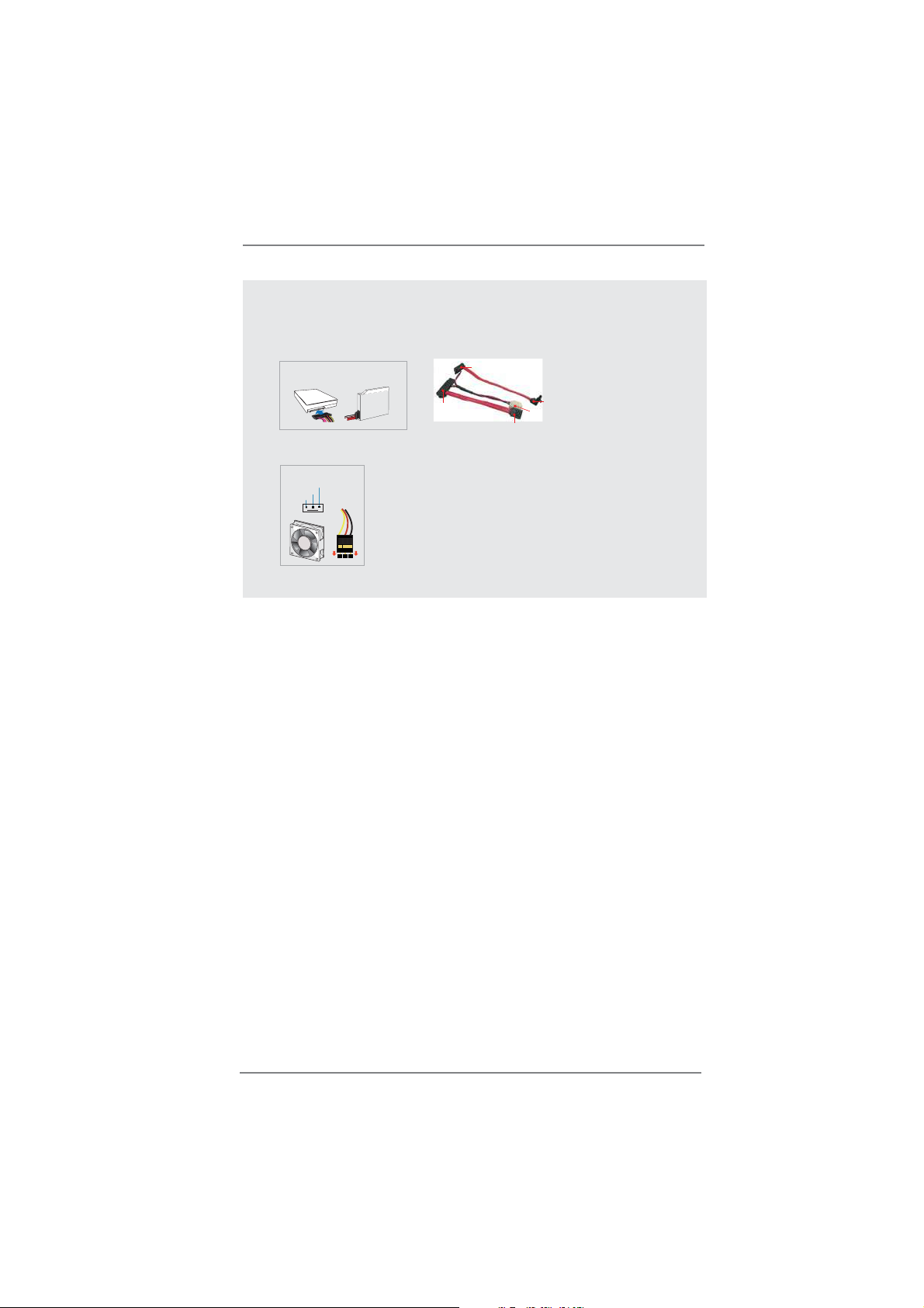
NOTE.
1. SATA and Power Connections
SATA &Power Connections
HDD
2. Fan Connection
Fan connector
Rotation
+12V
Ground
ODD
Connect toHDD
Connect toODD
Connect toATX5V Power Connector(3)
Connect toSATA Connector (1)
Connect toSATA Connector (4)
10
Page 11

1.4 Rear Panel Connectinos
14. HDMI connector
15. eSATA3 connector
16. DVI-I port (Dual-Link)
17. USB3.0 ports: USB devices
18. Mic In (Pink): Microphone
19. Optical S/PDIF Out port
20. DC-In jack
21. Side port for side speakers
22. Center/LFE (Orange): Center / subwoofer speakers
23. Front L/R Out (Lime): Stereo speakers or headphones
24. Line In (Blue) for 2/4/6 channel; Rear (Blue) for 8 channel
25. LAN (RJ-45) port: Local Area Network
26. USB2.0 ports: USB devices
11
Page 12

1.5 System Chassis
27. Headphone
28. Microphone
29. USB3.0 ports: USB devices
30. 4-in-1 Card reader (MMC/SD/MS/MS Pro)
31. Power ON/OFF button with status indicator
32. Slot-in Optical Disc Drive
12
Page 13
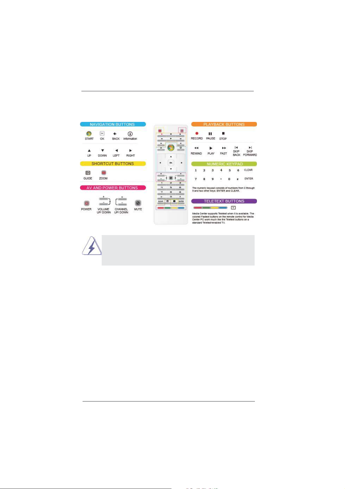
1.6 Remote Controller
Some remote controller functions listed above are only available with the
relative hardware equipments. If the hardware equipments you adopt are not
compatible with the system, you are not allowed to use these functions. This
product is designed to meet MCE standards.
13
Page 14
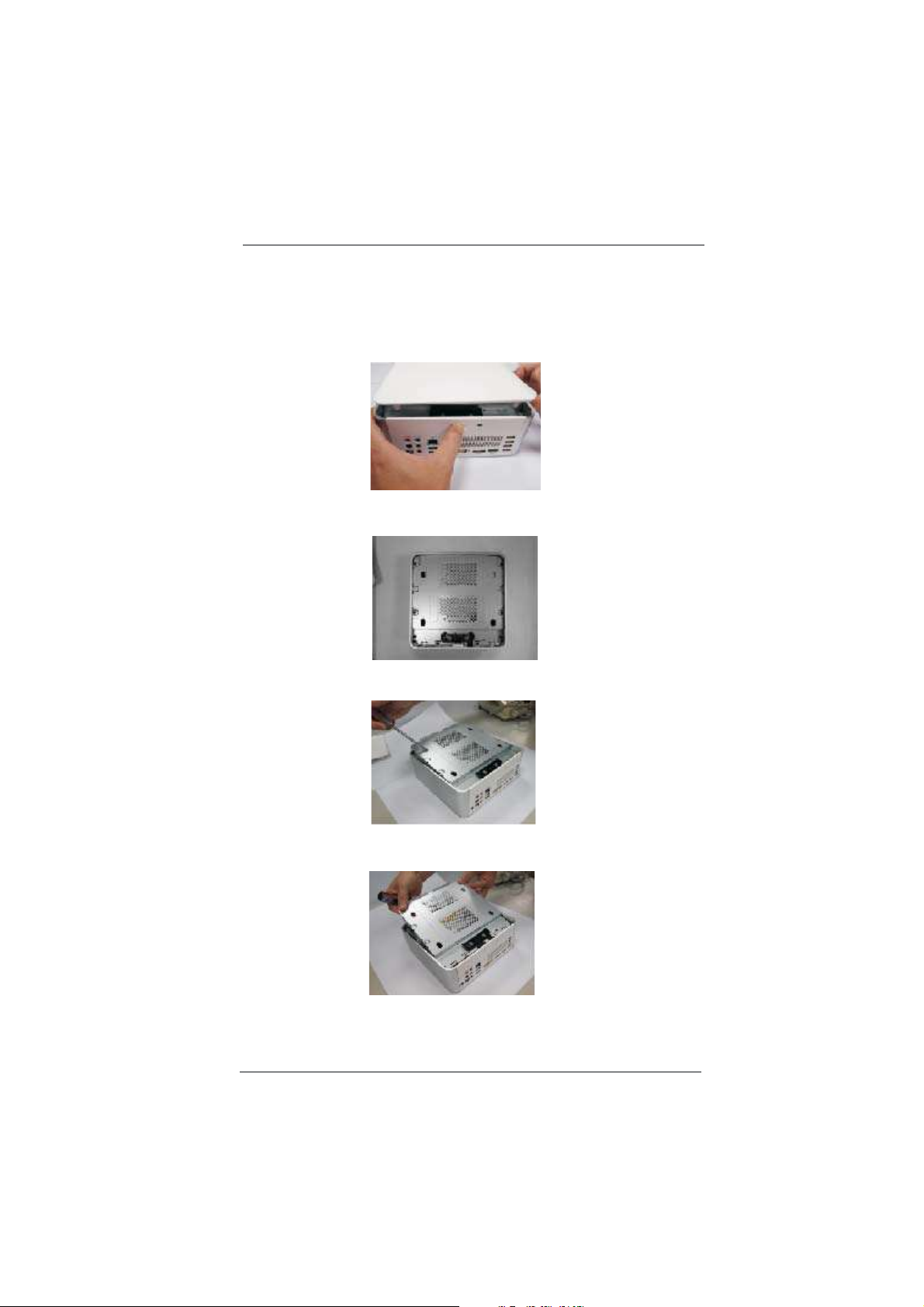
Chapter 2 Opening the chassis
1. Press the button on the rear I/O to open the top side of the chassis.
2. After the chassis is opened, you will see the top shield inside the
chassis.
3. Unscrew the screws on the corner of the top shield.
4. Carefully take the top shield out.
14
Page 15
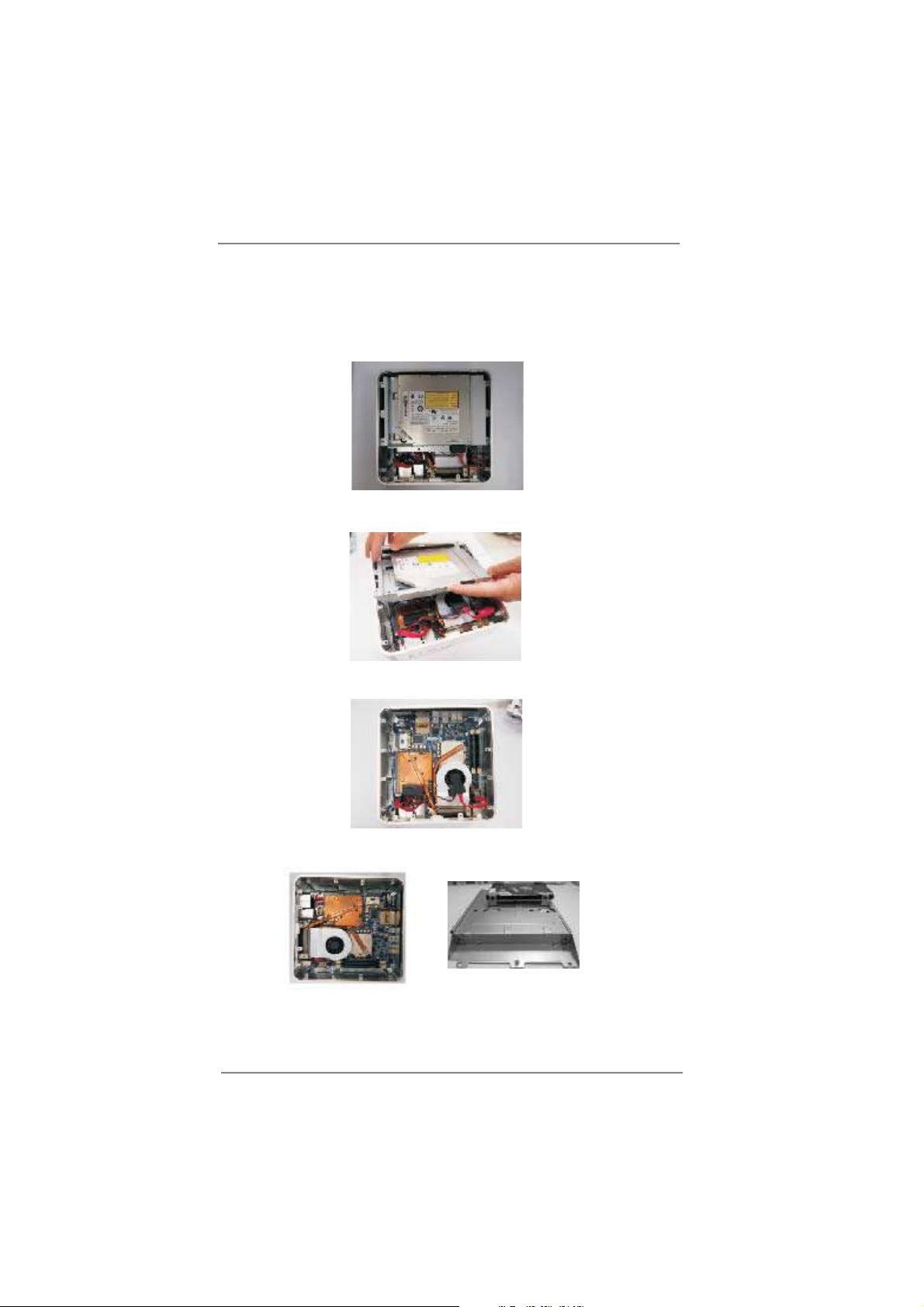
Chapter 3 Reinstalling the ODD/HDD
1. After you remove the top shield, you will see the ODD/HDD bracket.
2. Disconnect the ODD/HDD SATA power cable, and take out the ODD/HDD
bracket.
3. Disconnect all the ODD/HDD SATA power cables inside the chassis.
4. Then you can change the new ODD/HDD to upgrade your system.
15
Page 16

Chapter 4 Reinstalling the DIMMs
1. Unlock the DIMM slot by pressing the retaining clips outward to
change the DIMM.
16
Page 17
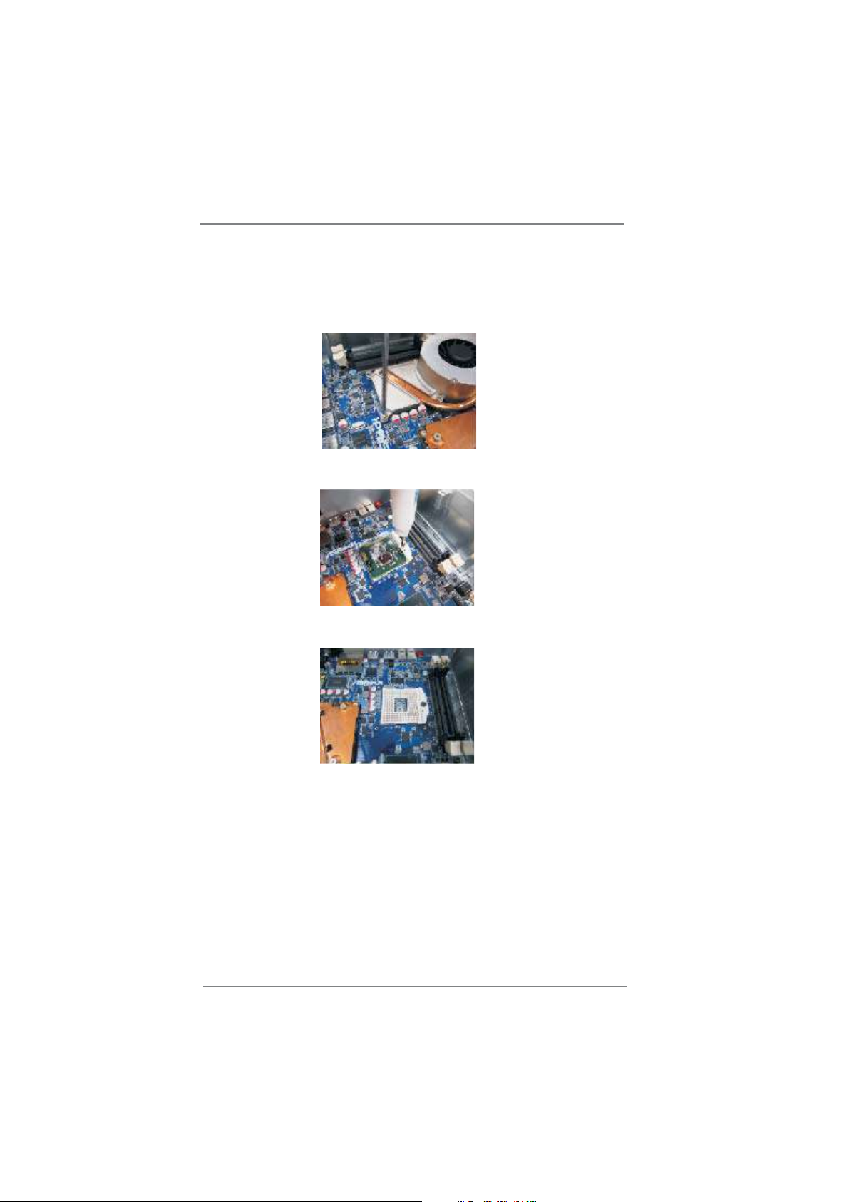
Chapter 5 Reinstalling the CPU
1. Unscrew the screws of the CPU fan.
2. Unscrew the screws on the corner of the CPU socket.
3. Now you can reinstall a new CPU to the system.
17
Page 18
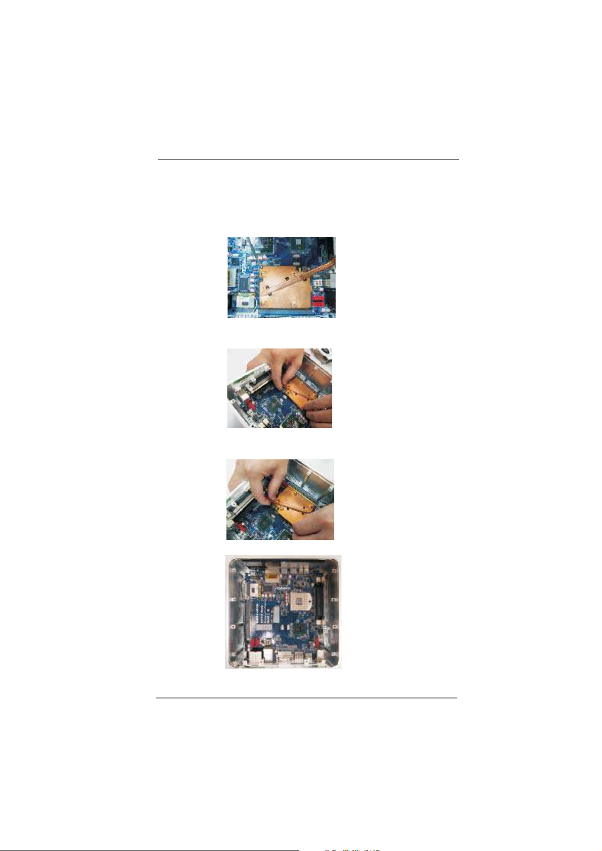
Chapter 6 Reinstalling the MXM card
1. Unscrew the screws of the heatpipe on the MXM card.
2. Use your fi ngers to pull the outer side of the heatpipe upward.
3. Finally you can take out the heatpipe and change a new MXM card.
18
Page 19
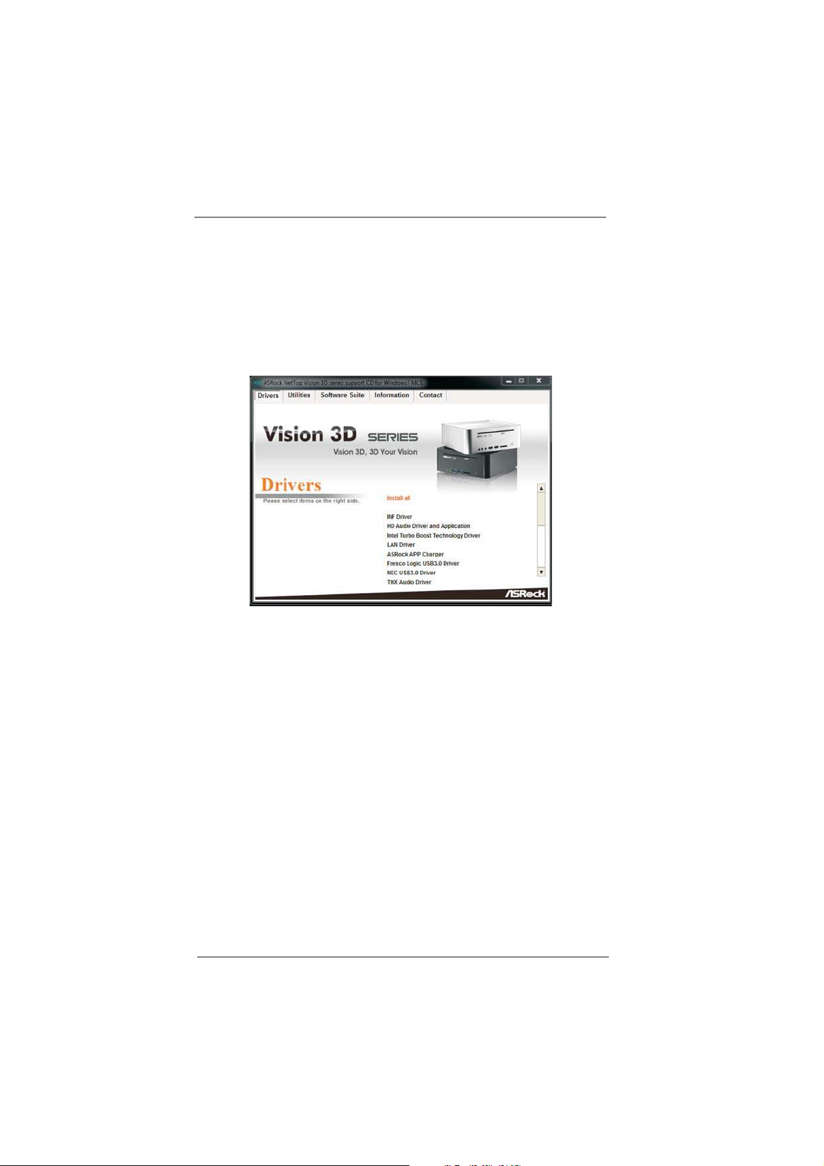
Chapter 7 Driver Installation
To install the drivers to your system, please insert the support CD to your optical
drive fi rst. Then, the drivers compatible to your system can be auto-detected and
listed on the support CD driver page. Please follow the order from up to bottom side
to install those required drivers. Therefore, the drivers you install can work properly.
19
Page 20

Chapter 8 Utility Menu
The utilities meu shows the applications and other software that this product supports.
8.1 Instant Boot
8.1.1 Introduction
Instant Boot, a user-friendly tool that allows you to turn on your PC in just a few
seconds, provides a much more effi cient way to save energy, time, money, and
improves system running speed for your system *. It is applicable to Windows®
7 / 7 64-bit / Vista™ / Vista™ 64-bit / XP / XP 64-bit.
Instant Boot leverages the S3 and S4 ACPI (Advanced Confi guration and
Power Interface) features which normally enable the Sleep/Standby and
Hibernation modes in Windows® to shorten boot up time. By calling S3 and S4
at specifi c timing during the shutdown and startup process, Instant Boot allows
you to enter your Windows® desktop in a few seconds.
There are two modes of Instant Boot available: Fast Mode and Regular
Mode. In Fast Mode, it uses S3 and takes only a few seconds for OS to
resume to working state, which is 10 times faster than traditional boot up
time (50 to 60 seconds). Even the Regular Mode is 3 times faster than traditional
boot up time.
20
Instant Boot guarantees a clean Windows® boot to consume less power,
time and money without any accumulated garbage data, and you can still
keep your data safe even there is a power cut. Also, the Windows® update
speed will become faster.
* This function is applicable ONLY to single user that does not secure ID and Password
to their systems.
* The boot up time depends on the hardware confi guration.
Page 21

8.1.2 Installation
Please read below procedures carefully before you install Instant Boot.
A. Install Instant Boot driver from ASRock support CD, or you may click
following link to get the latest utility and BIOS:
http://www.asrock.com/feature/InstantBoot/download.asp
B. Execute the Instant Boot installation program under Windows
follow the instructions on Instant Boot setup page.
a. Click “Next” to continue.
b. Select destination location. You may choose a different folder if you
need, and click “Next”.
®
. Please
c. Select the start menu folder. You may choose a different folder if you
need, and click “Next”.
21
Page 22

d. Click “Install” to begin installing Instant Boot driver.
e. Click “Finish” to complete and exit the setup.
C. After the installation is completed, you will fi nd an ASRock Instant Boot icon
on the Windows® desktop.
D. Double click ASRock Instant Boot icon on the desktop, then Instant Boot
main menu will pop up.
22
E. On Instant Boot main menu, you can choose “Fast Mode”, “Regular Mode” or
“Disable Instant Boot”. After that, please click “Apply” to save the change.
Please notice that you need to keep AC power on if you select “Fast Mode”.
F. When you want to shut down the computer, please simply select “Shut
Down” from Windows® “Start menu”.
G. Now, the system will restart once automatically. After reentering into
OS, the system will shutdown again.
Page 23

H. Next time when you turn on your system, you can enjoy the benefi t of
Instant Boot.
8.2 ASRock Extreme Tuning Utility (AXTU)
8.2.1 Introduction
ASRock Extreme Tuning Utility (AXTU) is an all-in-one tool to fi ne-tune different
system functions in a user-friendly interface, which is including Hardware
Monitor, Fan Control, Overclocking and OC DNA. In Hardware Monitor, it shows
the major readings of your system. In Fan Control, it shows the fan speed and
temperature for you to adjust. In Overclocking, you are allowed to overclock
CPU frequency for optimal system performance. In OC DNA, you can save your
OC settings as a profi le and share with your friends. Your friends then can load
the OC profi le to their own system to get the same OC settings.
8.2.2 Installation
When you install all-in-one driver to your system from ASRock support CD,
ASRock Extreme Tuning Utility (AXTU) will be auto-installed as well. After
installation, you will fi nd the icon “ASRock eXtreme Tuner“ on your desktop.
Double-click “ASRock eXtreme Tuner“ icon, AXTU main menu
will pop up.
8.2.3 Function
Please be noted that there is a button “Auto run when windows start“ on the
lower right corner. If you click this button, every time you turn on your system
and enter Windows®, the system will automatically start AXTU.
There are four sections in AXTU main menu: Hardware Monitor, Fan Control,
Overclocking and OC DNA.
23
Page 24

Hardware Monitor
In the Hardware Monitor section,
it shows the major readings of
your system. The main readings
include Clock, Fan & Temperature,
and Voltage. In Clock, there are
CPU speed and CPU ratio. In
Fan & Temperature, there are
CPU temperature and MXM GPU
temperature. You may find out if
there’s any abnormal situation occurs
to your system’s temperature. In
Voltage, there are many respective
voltages.
Fan Control
In the Fan Control section, there are
two major chapters: Temperature
and CPU Fan. In Temperature, it
shows the major readings of CPU
and MXM GPU temperature. In CPU
Fan, it shows the fan target speed
and temperature, and you are able to
adjust the setting by clicking the “+/-”
and confi rm by “APPLY” afterward.
24
Page 25

Overclocking
In the Overclocking section, there
are Clock and Voltage chapters
for parameter settings adjustment
in pursuit of optimal system
performance. You are able to finetune the CPU ratio, CPU frequency,
and respective voltages by clicking
the “+/-” at the display panel. After
confirmation of the settings, please
click on the “APPLY” button.
Overclocking and over-voltage may affect your system stability, or even
cause damage to your hardware devices. It should be done at your own
risk and expense. ASRock is not responsible for possible damage caused
by overclocking and and overvoltage. If system hangs after overclocking,
please remove AC power cord and plug AC power cord again before you
power on your system.
OC DNA
OC DNA provides a convenient
way to record the OC settings and
share with others. It helps you to
save your overclocking record under
the operating system and simplifies
the complicated recording process of
overclocking settings. With OC DNA,
you can save your OC settings as a
profile and share with your friends.
Your friends then can load the OC
profi le to their own system to get the
same OC settings as yours. Please
be noticed that the OC profile can
only be shared and worked on the
same motherboard.
25
Page 26

8.3 CyberLink DVD Suite free bundle (Trial version, including
PowerDVD, PowerDirector, etc)
CyberLink DVD Suite includes fi ve softwares: PowerDVD, PowerBackup,
PowerDirector, Power2Go and MediaShow. Please read below description for
details.
PowerDVD
World-renowned and award-winning PowerDVD delivers the ultimate DVD and highdefi nition movie experience on the PC. Feature-rich nevigation controls enhance
and personalize the movie experience. Moreover, the latest version comes with
leading video and audio technologies to deliver an exceptional level of viewing and
listening quality. PowerDVD is the obvious choice for anyone looking to enjoy DVDs
and high-defi nition Discs on the PC.
* The bundled PowerDVD is PowerDVD 8 DTS trial version, which only supports DVD playback
with DTS function. To play back other media such as Blu-ray or Dolby disc, please download
PowerDVD 9 trial version from CyberLink website: www.cyberlink.com
PowerBackup
PowerBackup is a powerful yet practical tool for protecting essential data, offering
a step-by-step approach to saving data onto a disc, a local hard drive, or via a
network.
26
Page 27

PowerDirector
CyberLink PowerDirector provides cool features to ensure editing movies is fun
and fast! Whether you are an advanced or entry-level video editor, PowerDirector
lets you enhance your camcorder videos and produce professional home movies.
PowerDirector offers a dual mode editing interface, comprehensive production tools,
technologies that save time and maintain your video quality, and a built-in CD/DVD
authoring program. It is your total video editing solution!
Power2Go
CyberLink Power2Go features two easy interfaces for handling all kinds of content.
Express mode allows simple drag-and-drop durning of Data, Music, and Video fi les,
as well as double-click activation of copying personal discs. Power2Go advanced
mode allows confi guration of burning and copying settings, in addition to utilities for
tasks such as ripping fi les and erasing discs.
MediaShow
MediaShow is an advanced software that lets you create, present and share
multimedia slide shows. It allows you to incorporate images, videos, audio clips
and even PowerPoint slides and add loads of transition effects, titling effects,
background music to create a dazzling slide show.
27
Page 28

8.4 CyberLink PowerDVD 10 Blu-ray 3D OEM version
PowerDVD 10
The No. 1 Movie Experience on PCs Upgrade Your Media Experience to HD &
3D
Upgrade your Blu-ray experience to whole new level with Blu-ray 3D and bring the
3D cinema experience back home with PowerDVD 10. With support for the latest 3D
hardware combined with PowerDVD's leading playback features and technologies,
PowerDVD 10 allows you to enjoy your movies like you're at the center of all the
actions.
Whether it is 3D movie content, captured home videos, or your digital music fi les,
PowerDVD 10 lets you access them all from the same convenient player software,
enhancing your experience in all kinds of new ways.
* PowerDVD 10 is bundled with Vision 3D BD only.
28
Page 29

8.5 Symantec Norton AntiVirus Software free bundle
(Trial version)
Protect your PC with Norton Internet Security, the fastest virus, spyware, Internet
protection. Norton Internet Security can stop online identity theft, viruses, spyware,
bots and more, stop attacks before they get on your PC, deliver clear threat and
performance explanations, identify unsafe web sites right in your search results, and
use intelligence-driven Norton Insight Network for faster, fewer, shorter scans.
29
Page 30

8.6 THX TruStudio Software free bundle
After you install THX audio driver from our support CD, there will be a THX icon
shown on the Windows® task bar.
®
Click the THX icon on the Windows
application as below, which provides Surround /Crystalizer/Speaker/Smart volume/
Dialog plus functions for you. Therefore, you can adjust your required function and
freely enjoy the benefi t of THX TruStudio.
task bar, you will see THX TruStudio software
30
Page 31

8.7 The best Apple charge companion
- ASRock APP Charger
Fast Charge & Charge Anytime!
If you desire a faster, less restricted way of charging your Apple devices, such as
iPhone/iPod/iPad Touch, ASRock has prepared a wonderful solution for
you ¡V ASRock App Charger. Simply installing the App Charger driver, it makes your
iPhone charged much quickly from your computer and up to 40%
faster than before*. ASRock App Charger allows you to quickly charge many Apple
devices simultaneously and even supports continuous charging when
your PC enters into Standby mode (S1), Suspend to RAM(S3), hibernation mode (S4)
or power off (S5)**. With App Charger driver installed, you can easily
enjoy the marvelous charging experience than ever.
31
Page 32

8.8 Lucid Virtu
8.8.1 Introduction
Lucid VIRTU solution is designed for Intel® Sandy Bridge platform with Intel® Processor Graphics enabled. VIRTU dynamically assigns tasks to best available graphics
resource based on power, performance and features. There is no need for HW or
HW changes. VIRTU allows user to fully utilize the unique capabilities of the Intel®’s
advanced media features on Sandy Bridge along with the high end 3D rendering
performance provided by the discrete GPU installed in the system.
This special version Lucid VIRTU provide the d-mode function for new Vision 3D
and allows it to utilize Intel® special features such as transcoding (quick sync).
* Currently, Lucid VIRTU solution is supported under Windows® 7 / 7 64-bit only.
32
Page 33

8.8.2 Installation
Notes
®
* Lucid VIRTU solution is designed for Intel
Sandy Bridge based
platforms only.
* GPU drivers and Lucid VIRTU solution should be installed before
running any graphic application.
* GPU drivers must be installed prior to Lucid VIRTU installation.
* It is recommended to restart the system after every driver installation.
1. Manually install Lucid VIRTU from our support CD. Double-click this
fi le to start installation. Lucid VIRTU is located in the following path of
our support CD:
..\ Drivers\Virtu\Lucid\Win7\Lucidlogix VIRTU Setup_32Bit.exe
..\ Drivers\Virtu\Lucid\Win7-64\Lucidlogix VIRTU Setup_64Bit.exe
2. The VIRTU Setup Wizard window is displayed.
3. Click Next. The End User License Agreement window is displayed.
4. Read the license agreement and select I accept the agreement.
33
Page 34

5. Click Next. Then Select Destination Location dialog box is displayed.
6. Click Next to accept the default location. Select Start Menu Folder window is
displayed.
7. Click Next to accept the default Start Menu folder. An information page is
displayed – please read it.
34
Page 35

8. Click Next. The Ready to Install dialog box is displayed.
9. Click Install to begin installation. The Installation window is displayed, indicating
the installation. This step may take a few minutes to complete.
10. When the installation is complete, “Completing the VIRTU Setup Wizard”
window is displayed.
Select “Yes, restart the computer now” option and click Finish. The VIRTU
installation process is completed.
35
Page 36

8.8.3 VIRTU Operation
After the installation process completed, VIRTU is activated. Once activated, the
Lucid logo shows on system tray (the right bottom corner of the screen). Mouse right
click at the icon, will display the following screen.
Clicking on the “Open control panel” option will open a new window with VIRTU control panel.
Clicking on “Disable” option, allows the user to stop VIRTU function.
Invisible or grey logo means VIRTU is not activated.
In case no logo is shown on the system tray, it is possible to activate the driver and
the control panel manually by using the following instructions:
1. Click “Start”, “Programs” and “VIRTU”.
2. Click using the right mouse button on “VIRTU Control Panel”.
In case logo icon is grey, use mouse right click while pointing at the logo to get the
following screen:
Clicking on the “Enable” option, will activate the VIRTU.
Typical application of VIRTU in can look like this:
36
Page 37

8.8.4 VIRTU Control Panel
Main Tab
When activating the VIRTU control panel (either from the start menu or from the
system tray icon), the following window is displayed:
By pressing a big “On” button VIRTU solution is activated. If “Show in System Tray”
is selected, a small control panel icon will be displayed on the system tray together
with the rest of the current running applications.
“In-Game icon” selection is used to enable/disable in game VIRTU logo indication.
The following options are available:
1. Show – The logo will be constantly displayed in the selected corner of the screen.
2. Show for a few seconds - The logo will be shown for a few second and then will
disappear.
3. Hide – No logo will be shown.
“Chose a Corner” – is a control to select a corner of the screen in which VIRTU logo
will be displayed.
“Performance optimization” – optimize the performance of the virtualization by using
special techniques. Test on each application in support list. In case of new application some issues may rarely happen it using full performance setting. In this case it
is recommended to change the setting to Quality.
37
Page 38

Games Tab
If the Games tab is selected, the following screen is displayed:
This screen shows the applications that VIRTU supports with the available graphic
cards. The application list is changed according to the graphic cards available in the
system and the current confi guration. The list includes the applications that meet
functionality and performance tests done by Lucid quality assurance.
VIRTU allows users to add new applications using the “Add”, “Edit” and “Remove”
buttons. Lucid cannot guarantee the functionality and performance of applications
that were not part of the Lucid qualifi ed application list provided with the product.
* Adding and editing of the applications list is disabled in evaluation versions of the
product.
When selecting the “Add” option, the following window is displayed:
Place the desired application full “exe” fi le path in the “exe name” box. Clicking
on the “…” button next to the “exe name” box allows using a standard Windows
browser to fi nd the location of the desired application “exe” fi le.
38
®
Page 39

The “Friendly name” box allows the user to give the desired application a name that
best describes the application. This is a free text box.
Press “OK” after fi lling the required information. This will automatically add and
application to the supported game list. Once the desired application will activate,
VIRTU will be applied to this application.
* Adding manually an application that was not originally part of the game list means
that the application did not pass Lucid QA tests. Lucid cannot guarantee the func tionality and performance of applications that were not part of the Lucid qualifi ed
application list provided with the driver.
About Tab
If the “About” tab is selected, the following screen is displayed:
This screen provides VIRTU version installed.
39
Page 40

8.9 CyberLink MediaEspresso 6.5 (Trial version)
CyberLink MediaEspresso 6.5 trial now supports Intel® Quick Sync Video hardware
transcoding and is optimized for second generation Core i7, i5, and i3 processors
to accelerated conversion of all your favorite media fi les for your favorite portable
players. Now you can easily display your favorite movies, songs and photos on
iPhone, iPad, PSP, XBox, Youtube, Facebook etc. Compile, convert and enjoy
images and songs as much as you want and enhance your videos to new levels
with TrueTheater Technology . Try it today!
Limitations:
30-day trial limitation
Convert videos to the H.264 format 50 times
40
Page 41

8.10 ASRock MAGIX Multimedia Suite - Exclusive
download software for ASRock cuntomers
MAGIX is a leading international provider of high-quality software, online services
and digital content for multimedia communications. Since 1993, MAGIX has
developed leading technologies for creating, editing, managing and presenting
photos, graphics, videos and music.
MAGIX operates internationally from branches in the USA, Canada, the UK, France,
Italy, Spain and the Netherlands. The product range is targeted towards both
laymen and professionals alike, going beyond the PC platform to include seamlessly
integrated online and mobile applications.
According to its retail sales fi gures, MAGIX leads in the multimedia software sector
in many important European markets, and is one of the most successful competitors
in the USA. Fifteen years of market presence and over a thousand awards
worldwide testify to the company’s power of innovation.
mufi n player
The next generation music player plays all standard audio
formats, manages large music collections, helps you discover
music, offers a free online hard drive and more.
Music Maker Silver
The easiest way to arrange, remix, record and create your own
music. Develop your musical style now - without any prior skills.
Video easy SE
With this program you can easily edit your movies, add
transitions, text and background music, and even quickly
enhance image and sound quality.
Photo Manager 10
Put an end to your digital photo chaos and organize photo
collections with ease. The program is fully equipped for fast
import, photo and video clip management, photo editing and
presentation.
41
Page 42

8.11 ASRock XFast USB Technology
- Faster Than Your Imagination!
Thank you for purchasing ASRock product! This product supports a revolutionary
technology, ASRock XFast USB Technology, which redefi nes the new standard
in high performance computing. ASRock dedicated hundreds of hard working
engineers to make immediate boosts possible – ASRock XFast USB Technology
instantly accelerates performance for the best possible gain profi les. Proving once
again to be the pioneer in computer industry, ASRock XFast USB Series products
integrate with the latest ASRock XFast USB Technology which delivers the world’s
fastest USB data transfer speed.
As we know, Windows® just assigns 10% system resource for one USB device.
However, ASRock XFast USB Technology creates a QOS (Quality of Service) to let
USB device more effi ciency. It changes USB protocol from single task to multi task
to deliver the best performance. With the unique ASRock XFast USB Technology
(Simulate as HDD NCQ technology), you will surprisingly fi nd the increase perfor-
mance of USB storage device, even faster than your imagination!
ASRock is always keen on providing innovative products and brings the unparalleled
performance to the real world! The latest ASRock XFast USB Technology was
successfully applied on ASRock motherboards. So, PC enthusiasts, what are you
waiting for? Quickly come to download the latest driver now!
* ASRock XFast USB Technology USB boost performance may depend on your hardware
confi guration.
42
Page 43

Please read below procedures carefully before you install ASRock XFast USB
Technology.
A. Install ASRock XFast USB driver from ASRock support CD. When you install
all-in-one driver to your system from ASRock support CD, ASRock XFast USB
driver will be auto-installed as well. You may click following link to get the latest
utility: http://www.asrock.com/Feature/XFastUSB/index.asp
B. After ASRock XFast USB driver is installed to your system successfully. You will
fi nd the icon “XFast USB“ on your desktop.
®
You can fi nd it on the Windows
task bar as well.
C. When you fi rst plug your USB device to the USB port of your computer. You will
see below message, “Please unplug and plug the disk again!“ Please unplug your
USB device and plug it to the USB port again. This message will not show in the
next time you use this USB device.
43
Page 44

D. Then, you will see ASRock XFast USB user interface as below. You can also
double-click the “XFast USB“ icon to show this interface. Please choose “Turbo“
to enable ASRock XFast USB Technology. The detailed information of your USB
device can also be found on this user interface.
44
Page 45

8.12 ASRock XFast LAN - Faster Internet Access
LAN Application Prioritization
You can confi gure your application priority
ideally and/or add new programs.
Lower Latency in Game
After setting online game priority higher, it
can lower the latency in game.
Traffi c Shaping
You can watch Youtube HD video and
download fi les simultaneously.
Real-Time Analysis of Your Data
With the status window, you can easily
recognize which data streams you are
currently transferring.
45
Page 46

Chapter 9: UEFI SETUP UTILITY
9.1 Introduction
This section explains how to use the UEFI SETUP UTILITY to confi gure your
system. The UEFI chip on the motherboard stores the UEFI SETUP UTILITY. You
may run the UEFI SETUP UTILITY when you start up the computer. Please press
<F2> or <Del> during the Power-On-Self-Test (POST) to enter the UEFI SETUP
UTILITY, otherwise, POST will continue with its test routines.
If you wish to enter the UEFI SETUP UTILITY after POST, restart the system by
pressing <Ctl> + <Alt> + <Delete>, or by pressing the reset button on the system
chassis. You may also restart by turning the system off and then back on.
Because the UEFI software is constantly being updated, the
following UEFI setup screens and descriptions are for reference
purpose only, and they may not exactly match what you see on
your screen.
9.1.1 UEFI Menu Bar
The top of the screen has a menu bar with the following selections:
Main To set up the system time/date information
OC Tweaker To set up overclocking features
Advanced To set up the advanced UEFI features
H/W Monitor To display current hardware status
Boot To set up the default system device to locate and load the
Operating System
Security To set up the security features
Exit To exit the current screen or the UEFI SETUP UTILITY
Use < > key or < > key to choose among the selections on the menu
bar, and then press <Enter> to get into the sub screen. You can also use the
mouse to click your required item.
46
Page 47

9.1.2 Navigation Keys
Please check the following table for the function description of each navigation
key.
Navigation Key(s) Function Description
/ Moves cursor left or right to select Screens
/ Moves cursor up or down to select items
+ / - To change option for the selected items
<Enter> To bring up the selected screen
<F1> To display the General Help Screen
<F9> To load optimal default values for all the settings
<F10> To save changes and exit the UEFI SETUP UTILITY
<ESC> To jump to the Exit Screen or exit the current screen
9.2 Main Screen
When you enter the UEFI SETUP UTILITY, the Main screen will appear and display
the system overview.
47
Page 48

9.3 OC Tweaker Screen
In the OC Tweaker screen, you can set up overclocking features.
CPU Control
CPU Ratio Setting
Use this item to change the ratio value of this motherboard.
Intel SpeedStep Technology
Intel SpeedStep technology is Intel’s new power saving technology. Pro-
cessor can switch between multiple frequency and voltage points to enable power savings. The default value is [Enabled]. Confi guration options:
[Auto], [Enabled] and [Disabled]. If you install Windows
[Auto], you need to set the “Power Schemes” as “Portable/Laptop” to enable this function. If you install Windows® VistaTM / 7 and want to enable
this function, please set this item to [Enabled]. This item will be hidden if
the current CPU does not support Intel SpeedStep technology.
®
XP and select
48
Please note that enabling this function may reduce CPU voltage and lead to system
stability or compatibility issue with some power supplies. Please set this item to
[Disable] if above issue occurs.
Intel Turbo Boost Technology
Use this item to enable or disable Intel Turbo Boost Technology. Turbo
Boost allows processor cores to run faster than marked frequency in
specifi c condition. The default value is [Enabled].
Turbo Boost Power Limit
Use this item to adjust Turbo Boost power limit. Confi guration options: [Auto]
and [Manual]. The default value is [Auto].
Page 49

DRAM Timing Control
DRAM Frequency
If [Auto] is selected, the motherboard will detect the memory module(s)
inserted and assigns appropriate frequency automatically.
CAS# Latency (tCL)
Use this item to change CAS# Latency (tCL) Auto/Manual setting. The
default is [Auto].
RAS# to CAS# Delay (tRCD)
Use this item to change RAS# to CAS# Delay (tRCD) Auto/Manual setting.
The default is [Auto].
Row Precharge Time (tRP)
Use this item to change Row Precharge Time (tRP) Auto/Manual setting.
The default is [Auto].
RAS# Active Time (tRAS)
Use this item to change RAS# Active Time (tRAS) Auto/Manual setting.
The default is [Auto].
Command Rate (CR)
Use this item to change Command Rate (CR) Auto/Manual setting. Min:
1N. Max: 2N. The default is [Auto].
Write Recovery Time (tWR)
Use this item to change Write Recovery Time (tWR) Auto/Manual setting.
The default is [Auto].
Refresh Cyle Time (tRFC)
Use this item to change Refresh Cyle Time (tRFC) Auto/Manual setting.
The default is [Auto].
RAS to RAS Delay (tRRD)
Use this item to change RAS to RAS Delay (tRRD) Auto/Manual setting.
The default is [Auto].
Write to Read Delay (tWTR)
Use this item to change Write to Read Delay (tWTR) Auto/Manual setting.
The default is [Auto].
Read to Precharge (tRTP)
Use this item to change Read to Precharge (tRTP) Auto/Manual setting.
The default is [Auto].
Four Activate Window (tFAW)
Use this item to change Four Activate Window (tFAW) Auto/Manual setting. The default is [Auto].
Memory Power Down Mode
Use this item to adjust DDR power down mode. Configuration options:
[Auto], [Slow] and [Fast]. The default value is [Auto].
49
Page 50

Voltage Control
DRAM Voltage
Use this to select DRAM Voltage. The default value is [Auto].
User Default
In this option, you are allowed to load and save three user defaults
according to your own requirements.
50
Page 51

9.4 Advanced Screen
In this section, you may set the confi gurations for the following items: CPU Confi gu-
ration, North Bridge Confi guration, South Bridge Confi guration, Storage Confi gura-
tion, Super IO Confi guration, ACPI Confi guration and USB Confi guration.
Setting wrong values in this section may cause
the system to malfunction.
Instant Flash
Instant Flash is a UEFI fl ash utility embedded in Flash ROM. This conve-
nient UEFI update tool allows you to update system UEFI without entering
operating systems fi rst like MS-DOS or Windows
and save the new UEFI fi le to your USB fl ash drive, fl oppy disk or hard
drive, then you can update your UEFI only in a few clicks without preparing an additional fl oppy diskette or other complicated fl ash utility. Please
be noted that the USB fl ash drive or hard drive must use FAT32/16/12 fi le
system. If you execute Instant Flash utility, the utility will show the UEFI
fi les and their respective information. Select the proper UEFI fi le to update
your UEFI, and reboot your system after UEFI update process completes.
®
. Just launch this tool
51
Page 52

9.4.1 CPU Configuration
Intel Hyper Threading Technology
To enable this feature, it requires a computer system with an Intel
processor that supports Hyper-Threading technology and an operating
system that includes optimization for this technology, such as Microsoft
Windows® XP / VistaTM / 7. Set to [Enabled] if using Microsoft® Windows®
XP, VistaTM, 7, or Linux kernel version 2.4.18 or higher. This option will be
hidden if the installed CPU does not support Hyper-Threading technology.
Active Processor Cores
Use this item to select the number of cores to enable in each processor
package. Confi guration options: [All] and [1]. The default value is [All].
Enhance Halt State (C1E)
All processors support the Halt State (C1). The C1 state is supported
through the native processor instructions HLT and MWAIT and requires no
hardware support from the chipset. In the C1 power state, the processor
maintains the context of the system caches.
CPU C3 State Support
Use this to enable or disable CPU C3 (ACPI C2) report to OS.
CPU C6 State Support
Use this to enable or disable CPU C6 (ACPI C3) report to OS.
Package C State Support
Selected option will program into C State package limit register. The
default value is [Auto].
Intel Virtualization Technology
When this option is set to [Enabled], a VMM (Virtual Machine Architecture)
can utilize the additional hardware capabilities provided by Vanderpool
Technology. This option will be hidden if the installed CPU does not
support Intel Virtualization Technology.
®
52
Page 53

No-Excute Memory Protection
No-Execution (NX) Memory Protection Technology is an enhancement
to the IA-32 Intel Architecture. An IA-32 processor with “No Execute (NX)
Memory Protection” can prevent data pages from being used by malicious
software to execute code. This option will be hidden if the current CPU
does not support No-Excute Memory Protection.
53
Page 54

9.4.2 North Bridge Configuration
VT-d
Use this to enable or disable Intel® VT-d technology (Intel® Virtualization
Technology for Directed I/O). The default value of this feature is [Disabled].
Quick Sync
Use this to enable Quick Sync for Lucid Virtu. This function is for Windows® 7 only. Please disable this option for other OS. The default value is
[Enabled].
54
Page 55

9.4.3 South Bridge Configuration
Restore on AC/Power Loss
This allows you to set the power state after an unexpected AC/power loss.
If [Power Off] is selected, the AC/power remains off when the power
recovers. If [Power On] is selected, the AC/power resumes and the
system starts to boot up when the power recovers.
Deep S5
Confi guration options: [Disabled] and [Auto]. If [Disabled] is selected, user
can use USB connector to charge under S5 state. If [Auto] is selected,
system will enter Deep S5 for S5 state if On/Off Play, Onboard Lan Power
On and USB KB/MS Power On are all disabled. The default value is [Auto].
Onboard LAN
This allows you to enable or disable the “Onboard LAN” feature.
Onboard HD Audio
Select [Auto], [Enabled] or [Disabled] for the onboard HD Audio feature. If
you select [Auto], the onboard HD Audio will be disabled when PCI Sound
Card is plugged.
On/Off Play
Use this item to enable or disable On/Off Play Technology. The default val-
ue is [Enabled]. When On/Off Play is enabled, Deep Sx will be disabled. If
you want to enable Deep Sx, please disable On/Off Play fi rst.
Onboard Card Reader
This allows you to enable or disable the onboard card reader. The default
value is [Enabled].
Legacy Support
This allows you to enable or disable the Legacy Support. The default value
is [Disabled].
55
Page 56

ACPI HPET Table
Use this item to enable or disable ACPI HPET Table. The default value is
[Enabled]. Please set this option to [Enabled] if you plan to use this
®
motherboard to submit Windows
VistaTM certifi cation.
Good Night LED
Enable this option to turn off Power LED and Port80 LED when the system
is power on. The keyboard LED will also be turned off in S1, S3 and S4
state. The default value is [Auto].
56
Page 57

9.4.4 Storage Configuration
SATA Mode
Use this to select SATA mode. Confi guration options: [IDE Mode], [AHCI
Mode] and [Disabled]. The default value is [AHCI Mode].
AHCI (Advanced Host Controller Interface) supports NCQ
and other new features that will improve SATA disk performance but IDE mode does not have these advantages.
SATA Aggressive Link Power Management
Use this to enable or disable SATA Aggressive Link Power Management.
The default value is [Enabled].
Hard Disk S.M.A.R.T.
Use this item to enable or disable the S.M.A.R.T. (Self-Monitoring, Analy-
sis, and Reporting Technology) feature. Confi guration options: [Disabled]
and [Enabled].
57
Page 58

9.4.5 Super IO Configuration
CIR Controller
Use this item to enable or disable the CIR controller.
58
Page 59

9.4.6 ACPI Configuration
Suspend to RAM
Use this item to select whether to auto-detect or disable the Suspend-toRAM feature. Select [Auto] will enable this feature if the OS supports it.
Check Ready Bit
Use this item to enable or disable the feature Check Ready Bit.
Onboard LAN Power On
Use this item to enable or disable onboard LAN to power on the system.
CIR Power On
Use this item to enable or disable CIR to power on the system.
RTC Alarm Power On
Use this item to enable or disable RTC (Real Time Clock) to power on the
system.
USB Keyboard/Remote Power On
Use this item to enable or disable USB keyboard/remote to power on the
system.
USB Mouse Power On
Use this item to enable or disable USB mouse to power on the system.
59
Page 60

9.4.7 USB Configuration
Front USB 3.0 Controller
Use this item to enable or disable the use of front USB 3.0 controller.
Rear USB 3.0 Controller
Use this item to enable or disable the use of rear USB 3.0 controller.
Legacy USB Support
Use this option to select legacy support for USB devices. There are four
confi guration options: [Enabled], [Auto], [Disabled] and [UEFI Setup Only].
The default value is [Enabled]. Please refer to below descriptions for the
details of these four options:
[Enabled] - Enables support for legacy USB.
[Auto] - Enables legacy support if USB devices are connected.
[Disabled] - USB devices are not allowed to use under legacy OS and
UEFI setup when [Disabled] is selected. If you have USB compatibility issue, it is recommended to select [Disabled] to enter OS.
[UEFI Setup Only] - USB devices are allowed to use only under UEFI
setup and Windows / Linux OS.
60
Page 61

9.5 Hardware Health Event Monitoring Screen
In this section, it allows you to monitor the status of the hardware on your system,
including the parameters of the CPU temperature, motherboard temperature, CPU
fan speed, chassis fan speed, and the critical voltage.
CPU Fan Setting
This allows you to set the CPU fan speed. Confi guration options: [Full On],
[SMART FAN Manual] and [Automatic Mode]. The default is value [Automatic Mode].
61
Page 62

9.6 Boot Screen
In this section, it will display the available devices on your system for you to confi g-
ure the boot settings and the boot priority.
Setup Prompt Timeout
This shows the number of seconds to wait for setup activation key.
65535(0XFFFF) means indefi nite waiting.
Bootup Num-Lock
If this item is set to [On], it will automatically activate the Numeric Lock
function after boot-up.
Full Screen Logo
Use this item to enable or disable OEM Logo. The default value is
[Enabled].
AddOn ROM Display
Use this option to adjust AddOn ROM Display. If you enable the option
“Full Screen Logo” but you want to see the AddOn ROM information
when the system boots, please select [Enabled]. Confi guration options:
[Enabled] and [Disabled]. The default value is [Enabled].
Boot From Onboard LAN
Use this item to enable or disable the Boot From Onboard LAN feature.
Boot Failure Guard
Enable or disable the feature of Boot Failure Guard.
Boot Failure Guard Count
Enable or disable the feature of Boot Failure Guard Count.
62
Page 63

9.7 Security Screen
In this section, you may set or change the supervisor/user password for the system.
For the user password, you may also clear it.
63
Page 64

9.8 Exit Screen
Save Changes and Exit
When you select this option, it will pop-out the following message, “Save
confi guration changes and exit setup?” Select [OK] to save the changes
and exit the UEFI SETUP UTILITY.
Discard Changes and Exit
When you select this option, it will pop-out the following message, “Discard
changes and exit setup?” Select [OK] to exit the UEFI SETUP UTILITY
without saving any changes.
Discard Changes
When you select this option, it will pop-out the following message, “Discard
changes?” Select [OK] to discard all changes.
Load UEFI Defaults
Load UEFI default values for all the setup questions. F9 key can be used
for this operation.
64
Page 65

Chapter 10 Software Support
10.1 Install Operating System
This system supports various Microsoft
/ Vista
TM
/ Vista
TM
64-bit / XP / XP 64-bit. Refer to your OS documentation for more
information.
10.2 Support CD Information
The Support CD contains necessary drivers and useful utilities that enhance the
system features.
10.2.1 Running The Support CD
To begin using the support CD, insert the CD into your CD-ROM drive. The
CD automatically displays the Main Menu if “AUTORUN” is enabled in your
computer. If the Main Menu did not appear automatically, locate and double
click on the fi le “ASSETUP.EXE” from the BIN folder in the Support CD to dis-
play the menus.
10.2.2 Drivers Menu
The Drivers Menu shows the available devices drivers if the system detects
installed devices. Please install the necessary drivers to activate the devices.
10.2.3 Utilities Menu
The Utilities Menu shows the applications software that the system supports.
Click on a specifi c item then follow the installation wizard to install it.
®
Windows® operating systems: 7 / 7 64-bit
10.2.4 Contact Information
If you need to contact ASRock or want to know more about ASRock, welcome
to visit ASRock’s website at http://www.asrock.com; or you may contact your
dealer for further information.
65
 Loading...