

Page 1
Copyright Notice:Copyright Notice:
Copyright Notice:
Copyright Notice:Copyright Notice:
No part of this installation guide may be reproduced, transcribed, transmitted, or translated in any language, in any form or by any means, except duplication of documentation by the purchaser for backup purpose, without written consent of ASRock Inc.
Products and corporate names appearing in this guide may or may not be registered
trademarks or copyrights of their respective companies, and are used only for identification or explanation and to the owners’ benefit, without intent to infringe.
Disclaimer:Disclaimer:
Disclaimer:
Disclaimer:Disclaimer:
Specifications and information contained in this guide are furnished for informational
use only and subject to change without notice, and should not be constructed as a
commitment by ASRock. ASRock assumes no responsibility for any errors or omissions
that may appear in this guide.
With respect to the contents of this guide, ASRock does not provide warranty of any kind,
either expressed or implied, including but not limited to the implied warranties or
conditions of merchantability or fitness for a particular purpose. In no event shall
ASRock, its directors, officers, employees, or agents be liable for any indirect, special,
incidental, or consequential damages (including damages for loss of profits, loss of
business, loss of data, interruption of business and the like), even if ASRock has been
advised of the possibility of such damages arising from any defect or error in the guide
or product.
This device complies with Part 15 of the FCC Rules. Operation is subject to the
following two conditions:
(1) this device may not cause harmful interference, and
(2) this device must accept any interference received, including interference that
may cause undesired operation.
CALIFORNIA, USA ONLY
The Lithium battery adopted on this motherboard contains Perchlorate, a toxic
substance controlled in Perchlorate Best Management Practices (BMP) regulations
passed by the California Legislature. When you discard the Lithium battery in
California, USA, please follow the related regulations in advance.
“Perchlorate Material-special handling may apply, see
www.dtsc.ca.gov/hazardouswaste/perchlorate”
ASRock Website: http://www.asrock.com
Published August 2009
Copyright©2009 ASRock INC. All rights reserved.
ASRock P55 Pro Motherboard
EnglishEnglish
EnglishEnglish
English
11
1
11
Page 2
English
EnglishEnglish
EnglishEnglish
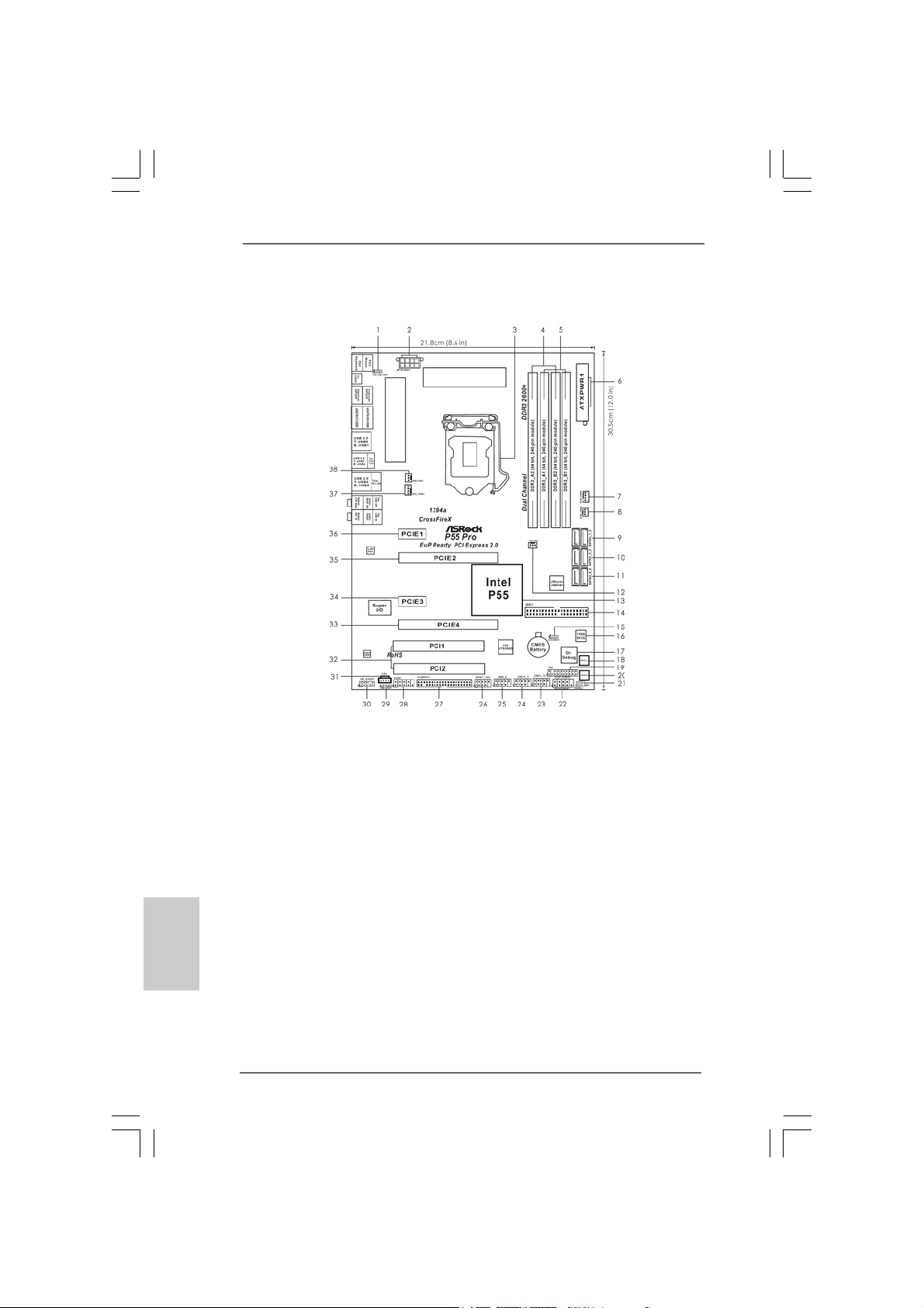
Motherboard LayoutMotherboard Layout
Motherboard Layout
Motherboard LayoutMotherboard Layout
1 PS2_USB_PWR1 Jumper 21 Infrared Module Header (IR1)
2 ATX 12V Power Conne ctor (A TX12V1) 22 System Panel Header (P ANEL1, Orange)
3 1156-Pin CPU Socket 23 USB 2.0 Header (USB12_13, Blue)
4 2 x 240-pin DDR3 DIMM Slots 24 USB 2.0 Header (USB10_11, Blue)
(Dual Channel: DDR3_A2, DDR3_B2, Blue) 25 USB 2.0 Header (USB8_9, Blue)
5 2 x 240-pin DDR3 DIMM Slots 26 Front Panel IEEE 1394 Header
(Dual Channel: DDR3_A1, DDR3_B1, White) (FRONT_1394, Red)
6 ATX Power Connector (ATXPWR1) 27 Floppy Connector (FLOPPY1)
7 Chassis Fan Connector (CHA_FAN1) 28 COM Port Header (COM1)
8 Chassis Fan Connector (CHA_FAN2) 29 HDMI_SPDIF Header
9 SAT AII Connector (SA T AII_1_2, Red) (HDMI_SPDIF1, Yellow)
10 SAT AII Connector (SA T AII_3_4, Red) 30 Front Panel Audio Header
11 SAT AII Connector (SA T AII_5_6, Red) (HD_AUDIO1, Lime)
12 Chassis Fan Connector (CHA_FAN3) 31 Internal Audio Connector: CD1 (Black)
13 Intel P55 Chipset 32 PCI Slots (PCI1-2)
14 Primary IDE Connector (IDE1, Blue) 33 PCI Express 2.0 x16 Slot (PCIE4, Orange)
15 Clear CMOS Jumper (CLRCMOS1) 34 PCI Express 2.0 x1 Slot (PCIE3, White)
16 16Mb SPI Flash 35 PCI Express 2.0 x16 Slot (PCIE2, Blue)
17 Dr. Debug 36 PCI Express 2.0 x1 Slot (PCIE1, White)
18 Reset Switch (RSTBTN) 37 CPU Fan Connector (CPU_FAN1)
19 TPM Header (TPM1) 38 Power Fan Connector (PWR_FAN1)
20 Power Switch (PWRBT N)
22
2
22
ASRock P55 Pro Motherboard
Page 3
I/O PI/O P
I/O P
I/O PI/O P
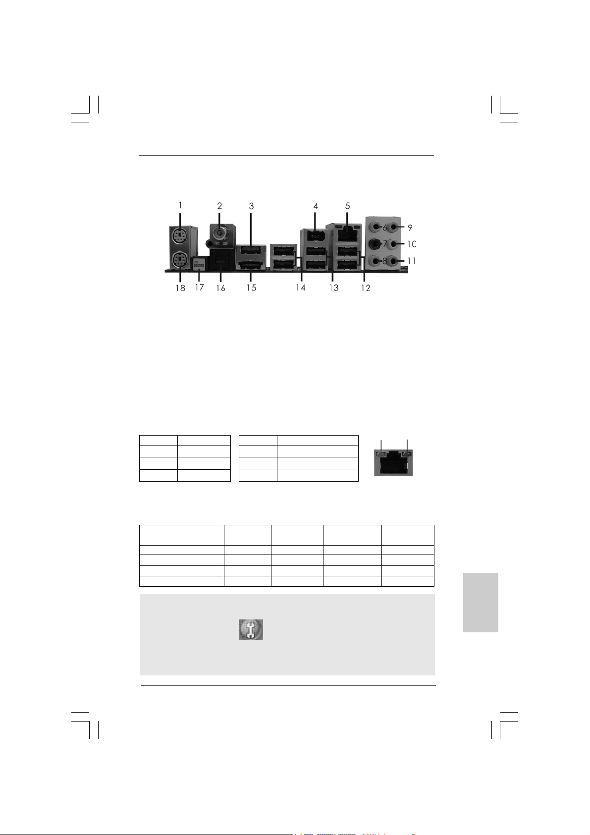
* 5 LAN RJ-45 Port 14 USB 2.0 Ports (USB01)
* There are two LED next to the LAN port. Please refer to the table below for the LAN port LED
indications.
** If you use 2-channel speaker, please connect the speaker’s plug into “Front Speaker Jack”.
See the table below for connection details in accordance with the type of speaker you use.
anelanel
anel
anelanel
1 PS/2 Mouse Port (Green) ** 10 Front Speaker (Lime)
2 Coaxial SPDIF Out Port 11 Microphone (Pink)
3 Powered eSAT AII/USB Connector 12 USB 2.0 Ports (USB45)
4 IEEE 1394 Port (IEEE 1394) 13 USB 2.0 Ports (USB23)
6 Side Speaker (Gray) 15 Powered eSATAII/USB Conne ctor
7 Rear Speaker (Black) 16 Optical SPDIF Out Port
8 Central / Bass (Orange) 17 Clear CMOS Switch (CLRCBTN)
9 Line In (Light Blue) 18 PS/2 Keyboard Port (Purple)
Activity/Link LED SPEED LED
Status Description Status Description
Off No Link Off 10Mbps connection
Blinking Data Activity Orange 100Mbps connection
On Link Green 1Gbps connection
Audio Output Channels Front Speaker Rear Speaker Central / Bass Side Speaker
2 V -- -- -4VV---6 VVV-8 VVVV
LAN Port LED Indications
TABLE for Audio Output Connection
(No. 10) (No. 7) (No. 8) (No. 6)
ACT/LINK
LED
LAN Port
SPEED
LED
To enable Multi-Streaming function, you need to connect a front panel audio cable to the front
panel audio header. After restarting your computer, you will find “Mixer” tool on your system.
Please select “Mixer ToolBox” , click “Enable playback multi-streaming”, and click
“ok”. Choose “2CH”, “4CH”, “6CH”, or “8CH” and then you are allowed to select “Realtek HDA
Primary output” to use Rear Speaker, Central/Bass, and Front Speaker, or select “Realtek
HDA Audio 2nd output” to use front panel audio.
ASRock P55 Pro Motherboard
EnglishEnglish
EnglishEnglish
English
33
3
33
Page 4
1. Introduction1. Introduction
1. Introduction
1. Introduction1. Introduction
Thank you for purchasing ASRock P55 Pro motherboard, a reliable motherboard
produced under ASRock’s consistently stringent quality control. It delivers excellent
performance with robust design conforming to ASRock’s commitment to quality and
endurance.
This Quick Installation Guide contains introduction of the motherboard a nd step-by-ste p
installation guide. More detailed information of the motherboard can be f ound in the user
manual presented in the Support CD.
Because the motherboard specifications and the BIOS software might
be updated, the content of this manual will be subject to change without
notice. In case any modifications of this manual occur, the updated
version will be available on ASRock website without further notice. You
may find the latest VGA cards and CPU support lists on ASRock website
as well. ASRock website http://www.asrock.com
If you require technical support related to this motherboard, please visit
our website for specific information about the model you are using.
www.asrock.com/support/index.asp
1.1 Package Contents1.1 Package Contents
1.1 Package Contents
1.1 Package Contents1.1 Package Contents
ASRock P55 Pro Motherboard
(ATX Form Factor: 12.0-in x 8.6-in, 30.5 cm x 21.8 cm)
ASRock P55 Pro Quick Installation Guide
ASRock P55 Pro Support CD
1 x 80-conductor Ultra ATA 66/100/133 IDE Ribbon Cable
1 x Ribbon Cable for a 3.5-in Floppy Drive
4 x Serial ATA (SATA) Data Cables (Optional)
1 x Serial ATA (SATA) HDD Power Cables (Optional)
1 x I/O Panel Shield
English
EnglishEnglish
EnglishEnglish
44
4
44
ASRock P55 Pro Motherboard
Page 5
1.21.2
SpecificationsSpecifications
1.2
Specifications
1.21.2
SpecificationsSpecifications
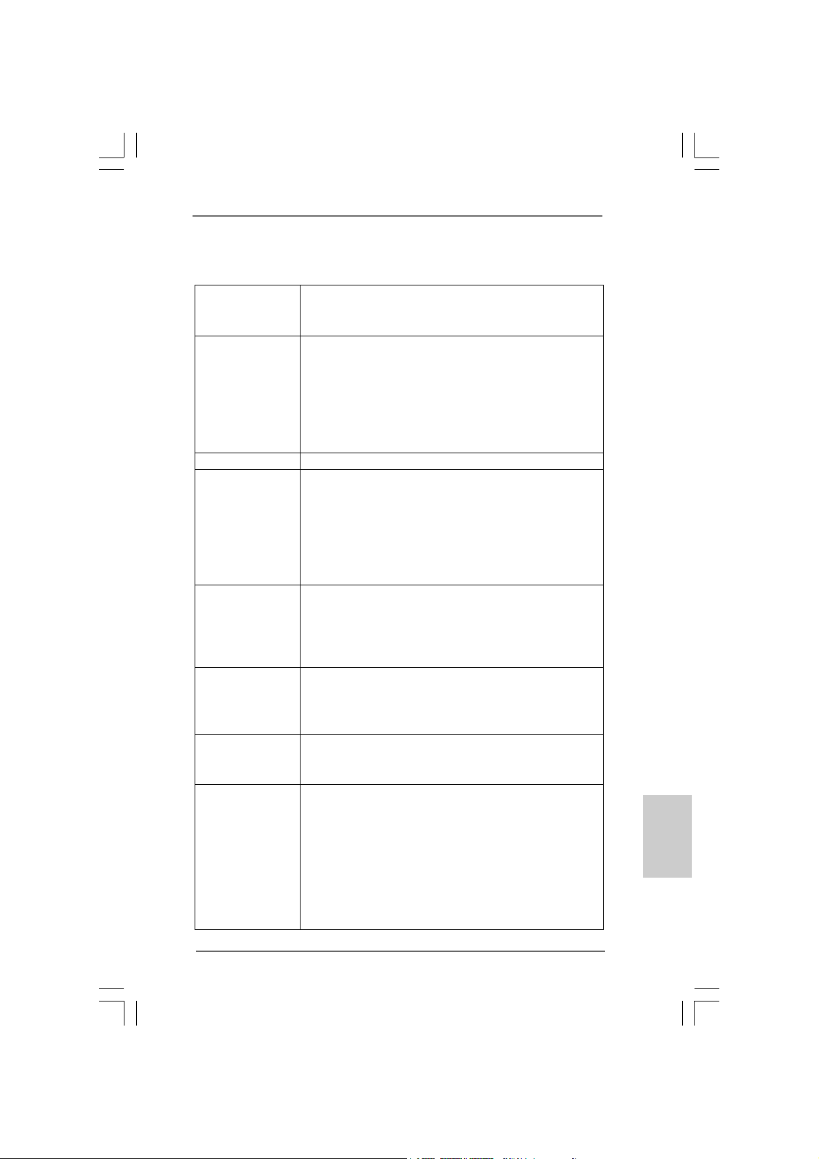
Platform - ATX Form Factor: 12.0-in x 8.6-in, 30.5 cm x 21.8 cm
- All Solid Capacitor design (100% Japan-made high-quality
Conductive Polymer Capacitors)
CPU - Supports the Intel® CoreTM i7 and Intel® CoreTM i5 Processors
in the LGA1156 Package
- Advanced V8 + 2 Power Phase Design
- Supports Intel® Turbo Boost Technology
- Supports Hyper-Threading Technology (see CAUTION 1)
- Supports Untied Overclocking Technology (see CAUTION 2)
- Supports EM64T CPU
Chipset - Intel® P55
Memory - Dual Channel DDR3 Memory T echnology (see CAUTION 3)
- 4 x DDR3 DIMM slots
- Supports DDR3 2600+(OC)/2133(OC)/1866(OC)/1600/
1333/1066 non-ECC, un-buffered memory
- Max. capacity of system memory: 16GB (see CAUTION 4)
- Supports Intel® Extreme Memory Profile (XMP)
(see CAUTION 5)
Expansion Slot - 1 x PCI Express 2.0 x16 slot (at x16 mode)
- 1 x PCI Express 2.0 x16 slot (at x4 mode, 2.5GT/s)
- 2 x PCI Express 2.0 x1 slots (2.5GT/s)
- 2 x PCI slots
- Supports ATITM CrossFireXTM and Quad CrossFireX
Audio - 7.1 CH Windows® VistaTM Premium Level HD Audio with
Content Protection
- DAC with 110dB dynamic range (ALC890 Audio Codec)
- Premium Blu-ray audio support
LAN - PCIE x1 Gigabit LAN 10/100/1000 Mb/s
- Realtek RTL81 11DL
- Supports Wake-On-LAN
Rear Panel I/O I/O Panel
- 1 x PS/2 Mouse Port
- 1 x PS/2 Keyboard Port
- 1 x Coaxial SPDIF Out Port
- 1 x Optical SPDIF Out Port
- 6 x Ready-to-Use USB 2.0 Ports
- 2 x Powered eSATAII/USB Connectors
- 1 x RJ-45 LAN Port with LED (ACT/LINK LED and SPEED
LED)
TM
EnglishEnglish
EnglishEnglish
English
ASRock P55 Pro Motherboard
55
5
55
Page 6
English
EnglishEnglish
EnglishEnglish
66
6
66
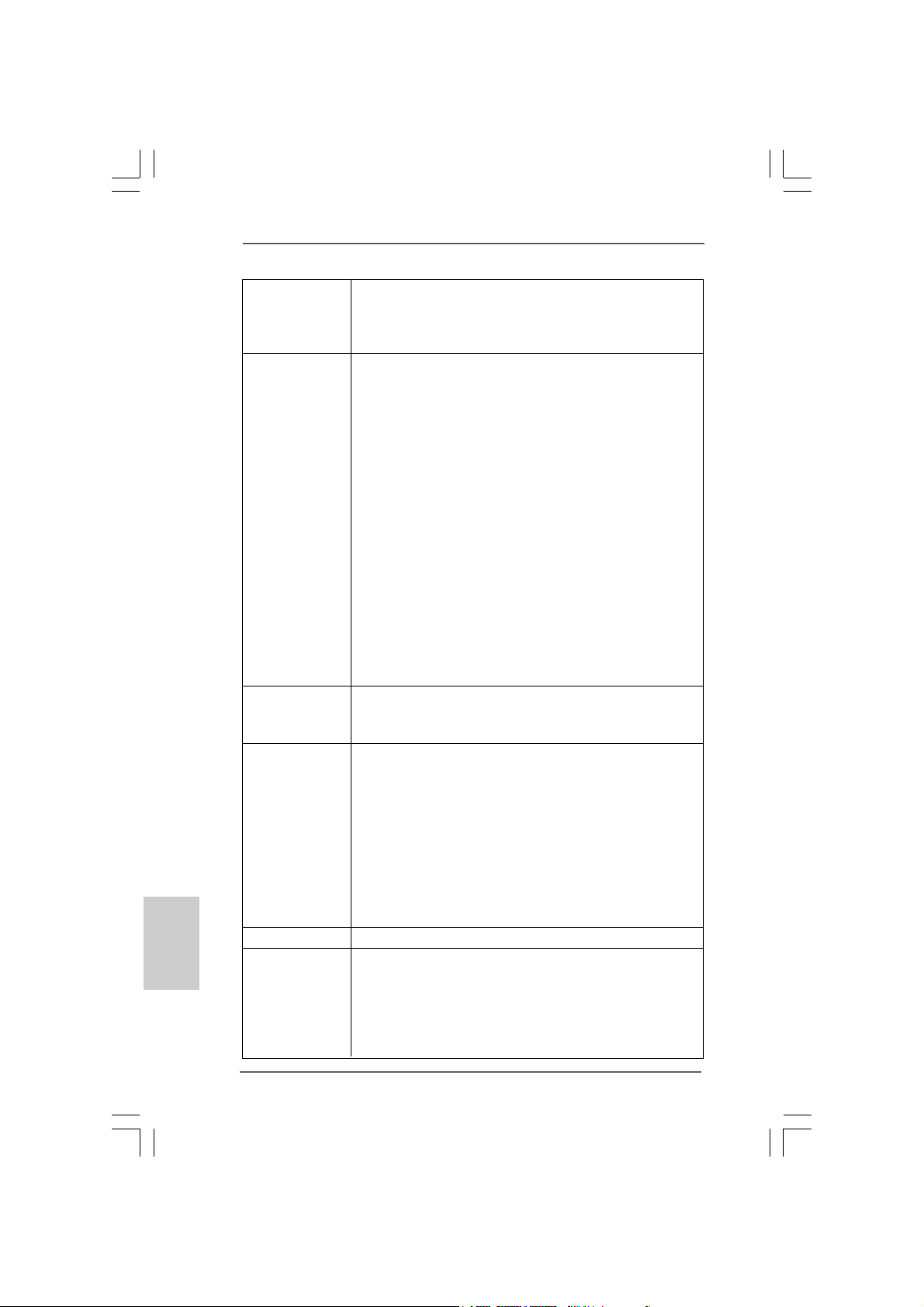
- 1 x IEEE 1394 Port
- 1 x Clear CMOS Switch with LED
- HD Audio Jack: Side Speaker/Rear Speaker/Central/Bass/
Line in/Front Speaker/Microphone (see CAUTION 6)
Connector - 6 x SATAII 3.0Gb/s connectors, support RAID (RAID 0,
RAID 1, RAID 10, RAID 5 and Intel Matrix Storage), NCQ,
AHCI and “Hot Plug” functions (see CAUTION 7)
- 1 x ATA133 IDE connector (supports 2 x IDE devices)
- 1 x Floppy connector
- 1 x IR header
- 1 x COM port header
- 1 x HDMI_SPDIF header
- 1 x IEEE 1394 header
- 1 x TPM header
- CPU/Chassis/Power FAN connector
- 24 pin ATX power connector
- 8 pin 12V power connector
- CD in header
- Front panel audio connector
- 3 x USB 2.0 headers (support 6 USB 2.0 ports)
(see CAUTION 8)
- 1 x Dr. Debug (7-Segment Debug LED)
Smart Switch - 1 x Clear CMOS Switch with LED
- 1 x Power Switch with LED
- 1 x Reset Switch with LED
BIOS Feature - 16Mb AMI BIOS
- AMI Legal BIOS
- Supports “Plug and Play”
- ACPI 1.1 Compli ance Wake Up Events
- Supports jumperfree
- SMBIOS 2.3.1 Support
- CPU, VCCM, SB, VTT , VCCM REF, PCH_PLL V oltage
Multi-adjustment
- Supports I. O. T. (Intelligent Overclocking Technology)
- Supports Smart BIOS
Support CD - Drivers, Utilities, AntiVirus Software (Trial Version)
Unique Feature - ASRock OC Tuner (see CAUTION 9)
- Intelligent Energy Saver (see CAUTION 10)
- Instant Boot
- ASRock Instant Flash (see CAUTION 11)
- Hybrid Booster:
- CPU Frequency Stepless Control (see CAUTION 12)
ASRock P55 Pro Motherboard
Page 7
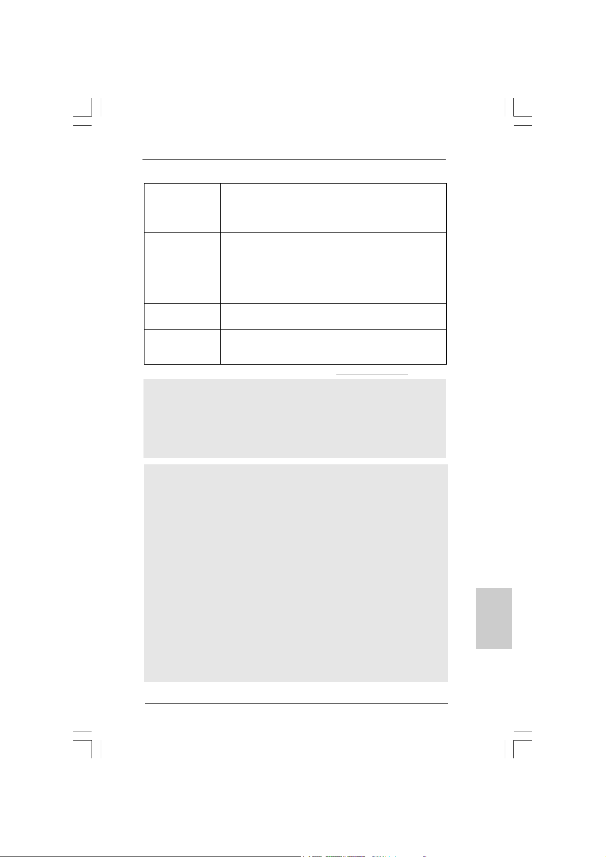
- ASRock U-COP (see CAUTION 13)
- Boot Failure Guard (B.F.G.)
- Combo Cooler Option (C.C.O.) (see CAUTION 14)
- Good Night LED
Hardware - CPU Temperature Sensing
Monitor - Chassis Temperature Sensing
- CPU/Chassis/Power Fan Tachometer
- CPU Quiet Fan
- CPU/Chassis Fan Multi-Speed Control
- Voltage Monitoring: +12V, +5V, +3.3V, CPU Vcore
OS - Microsoft® Windows® XP / XP 64-bit / Vista
TM
/ VistaTM 64-bit
/ Win7 compliant
Certifications - FCC, CE, WHQL
- EuP Ready (EuP ready power supply is required)
(see CAUTION 15)
* For detailed product information, please visit our website: http://www.asrock.com
WARNING
Please realize that there is a certain risk involved with overclocking, including adjusting
the setting in the BIOS, applying Untied Overclocking Technology, or using the thirdparty overclocking tools. Overclocking may affect your system stability, or even
cause damage to the components and devices of your system. It should be done at
your own risk and expense. We are not responsible for possible damage caused by
overclocking.
CAUTION!
1. About the setting of “Hyper Threading Technology”, please check page 55
of “User Manual” in the support CD.
2. This motherboard supports Untied Overclocking Technology. Please read
“Untied Overclocking Technology” on page 31 for details.
3. This motherboard supports Dual Cha nnel Me mory Technology . Before you
implement Dual Channel Memory Technology, make sure to read the
installation guide of memory modules on page 13 for proper installation.
4. Due to the operating system limitation, the actual memory size may be
less than 4GB for the reservation for system usage under Windows® XP
and Windows® VistaTM. For Windows® XP 64-bit and Windows® VistaTM 64bit with 64-bit CPU, there is no such limitation.
5. For those CPU that only support up to DDR3 1333, the XMP DDR3 1600
is supported through overclocking.
6. For microphone input, this motherboard supports both stereo and mono
modes. For audio output, this motherboard supports 2-channel, 4-channel,
6-channel, and 8-channel modes. Please check the table on page 3 for
proper connection.
EnglishEnglish
EnglishEnglish
English
ASRock P55 Pro Motherboard
77
7
77
Page 8
English
EnglishEnglish
EnglishEnglish
7. Before installing SATAII hard disk to SATAII connector, please read the
“SATAII Hard Disk Setup Guide” on page 36 of “User M a nual” in the support
CD to adjust your SATAII hard disk drive to SATAII mode. You can also
connect SATA hard disk to SATAII connector directly.
8. Power Management for USB 2.0 works fine under Microsoft® Windows
VistaTM 64-bit / VistaTM / XP 64-bit / XP SP1 or SP2.
9. It is a user-friendly ASRock overclocking tool which allows you to surveil
your system by hardware monitor function and overclock your hardware
devices to get the best system performance under Windows® environment.
Please visit our website for the operation procedures of ASRock OC
Tuner.
ASRock website: http://www.asrock.com/feature/OCTuner/index.htm
10. Featuring an advanced proprietary hardware and software design,
Intelligent Energy Saver is a revolutionary technology that delivers
unparalleled power savings. In other words, it is able to provide exceptional
power saving and improve power efficiency without sacrificing computing
performance. Please visit our website for the operation procedures of
Intelligent Energy Saver.
ASRock website: http://www.asrock.com/feature/IES/index.html
11. ASRock Instant Flash is a BIOS flash utility embedded in Flash ROM.
This convenient BIOS update tool allows you to update system BIOS
without entering operating systems first like MS-DOS or Windows®. With
this utility, you can press <F6> key during the POST or press <F2> key to
BIOS setup menu to access ASRock Instant Flash. Just launch this tool
and save the new BIOS file to your USB flash drive, floppy disk or hard
drive, then you can update your BIOS only in a few clicks without preparing an additional floppy diskette or other complicated flash utility. Please
be noted that the USB flash drive or hard drive must use FAT32/16/12 file
system.
12. Although this motherboard offers stepless control, it is not recommended
to perform over-clocking. Frequencies other than the recommended CPU
bus frequencies may cause the instability of the system or damage the
CPU.
13. While CPU overheat is detected, the system will automatically shutdown.
Before you resume the system, please check if the CPU fan on the
motherboard functions properly and unplug the power cord, then plug it
back again. To improve heat dissipation, remember to spray thermal
grease between the CPU a nd the he atsink when you install the PC syste m.
14. Combo Cooler Option (C.C.O.) provides the flexible option to adopt two
different CPU cooler types, Socket LGA 775 and LGA 1156. Please be
noticed that not all the 775 CPU Fan can be used.
15. EuP, stands for Energy Using Product, was a provision regulated by
European Union to define the power consumption for the completed system.
According to EuP, the total AC power of the completed system shall be
under 1.00W in off mode condition. To meet EuP standard, an EuP ready
motherboard and an EuP ready power supply are required. According to
®
88
8
88
ASRock P55 Pro Motherboard
Page 9
Intel’s suggestion, the EuP ready power supply must meet the standard of
5v standby power efficiency is higher than 50% under 100 mA current
consumption. For EuP ready power supply selection, we recommend you
checking with the power supply manufacturer for more details.
TMTM
TM
1.31.3
TT
1.3
1.31.3
wo CrossFwo CrossF
T
wo CrossF
TT
wo CrossFwo CrossF
(for Windows® XP / XP 64-bit / VistaTM / VistaTM 64-bit)
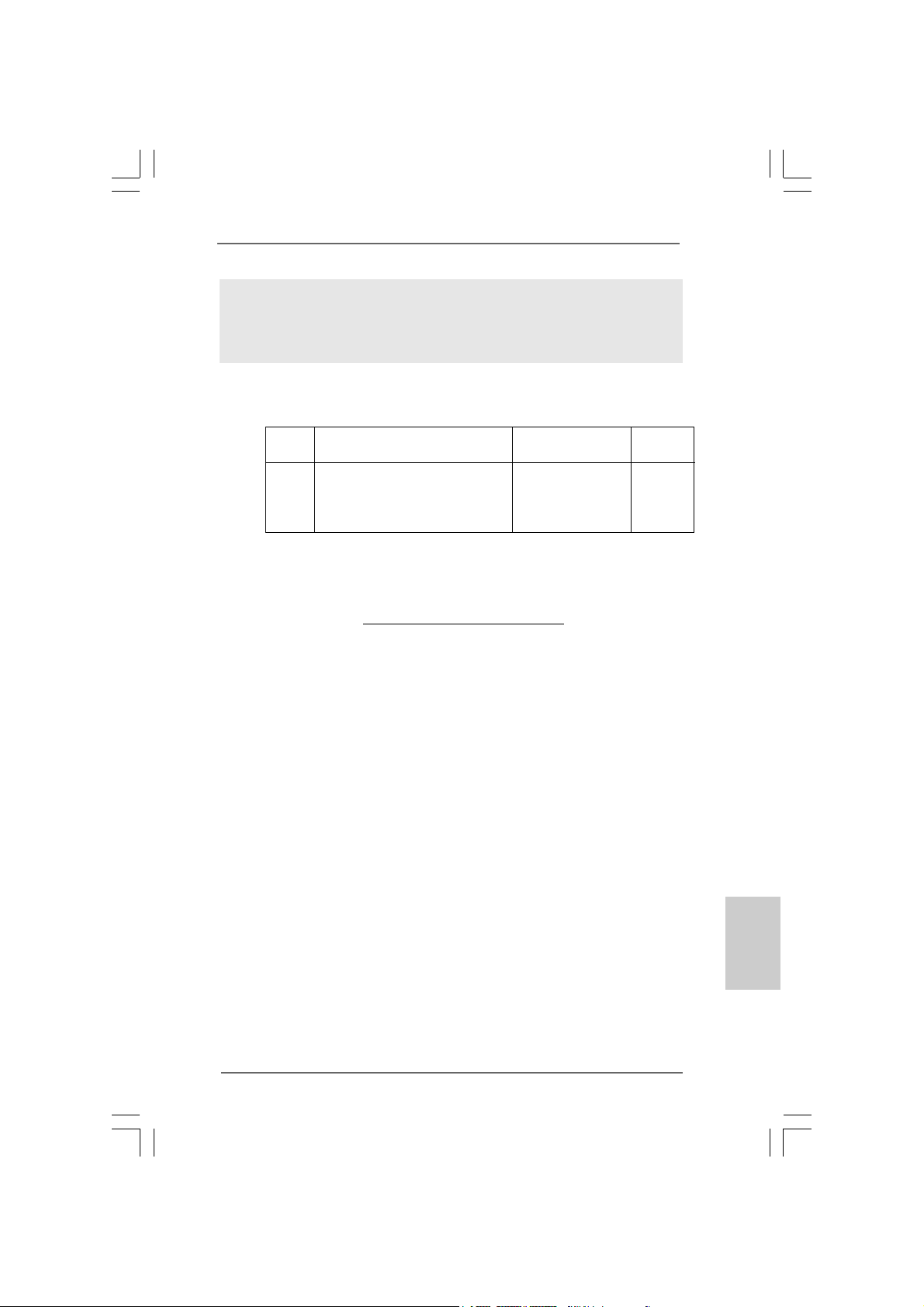
Chipset Model Name C h ipset Name Driver
Vendor
ATI
* The graphics cards with * mark are supported under Windows® VistaTM / VistaTM 64-bit
only.
* For the latest updates of the supported PCI Express VGA card list for
CrossFireXTM Mode, please visit our website for details.
ASRock website: http://www.asrock.com/support/index.htm
MSI RX2600PRO-T2D256EZ Radeon HD 2600PRO Catalyst 9.1
Gigabyte GV -RX26T256HP-B Radeon HD 2600XT Catalyst 9.1
ASUS EAH4350 SILENT/DI/512MD2/A RADEON HD 4350 Catalyst 9.1
ASUS EAH4870X2/HDTI/2G * RADEON HD 4870X2 Catalyst 9.1
TMTM
ireXireX
Graphics Card Suppor Graphics Card Suppor
ireX
Graphics Card Suppor
ireXireX
Graphics Card Suppor Graphics Card Suppor
t Listt List
t List
t Listt List
ASRock P55 Pro Motherboard
EnglishEnglish
EnglishEnglish
English
99
9
99
Page 10
2.2.
InstallationInstallation
2.
Installation
2.2.
InstallationInstallation
Pre-installation PrecautionsPre-installation Precautions
Pre-installation Precautions
Pre-installation PrecautionsPre-installation Precautions
Take note of the following precautions before you install motherboard components or change any motherboard settings.
1. Unplug the power cord from the wall socket before touching any
component. Failure to do so may cause severe damage to the
motherboard, peripherals, and/or components.
2. To avoid damaging the motherboard components due to static
electricity, NEVER place your motherboard directly on the carpet
or the like. Also remember to use a grounded wrist strap or touch
a safety grounded object before you handle components.
3. Hold components by the edges and do not touch the ICs.
4. Whenever you uninstall any component, place it on a grounded
antstatic pad or in the bag that comes with the component.
5. When placing screws into the screw holes to secure the
motherboard to the chassis, please do not over-tighten the
screws! Doing so may damage the motherboard.
2.12.1
CPU InstallationCPU Installation
2.1
CPU Installation
2.12.1
CPU InstallationCPU Installation
For the installation of Intel 1156-Pin CPU,
please follow the steps below.
English
EnglishEnglish
EnglishEnglish
1010
10
1010
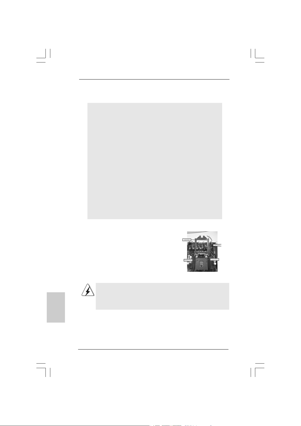
1156-Pin Socket Overview
Before you insert the 1156-Pin CPU into the socket, please check if
the CPU surface is unclean or if there is any bent pin on the socket.
Do not force to insert the CPU into the socket if above situation is
found. Otherwise, the CPU will be seriously damaged.
ASRock P55 Pro Motherboard
Page 11
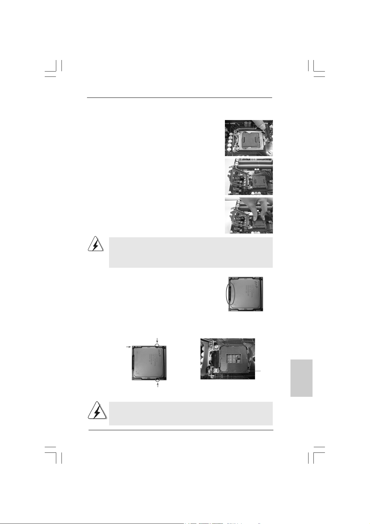
Step 1. Open the socket:
Step 1-1. Disengaging the lever by depressing
down and out on the hook to clear retention tab.
Step 1-2. Rotate the load lever to fully open posi-
tion at approxi mately 135 degrees .
Step 1-3. Rotate the load plate to fully open posi-
tion at approxi mately 100 degrees .
Step 2. Remove PnP Cap (Pick a nd Pla ce Cap).
1. It is recommended to use the cap tab to handle and avoid kicking
off the PnP cap.
2. This cap must be placed if returning the motherboard for after
service.
Step 3. Insert the 1 156-Pin CPU:
Step 3-1. Hold the CPU by the edges where are
marked with black lines.
black line
Step 3-2. Orient the CPU with IHS (Integrated Heat
Sink) up. Locate Pin1 and the two orientation key notches.
orientation key notch
Pin1
orientation key notch
1156-Pin CPU
For proper inserting, please ensure to match the two orientation
key notches of the CPU with the two alignment keys of the
socket.
ASRock P55 Pro Motherboard
alignment key
alignment key
1156-Pin Socket
Pin1
1111
11
1111
EnglishEnglish
EnglishEnglish
English
Page 12
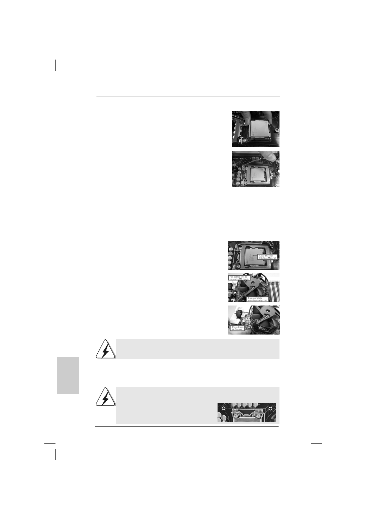
Step 3-3. Carefully pla ce the CPU into the socket
by using a purely vertical motion.
Step 3-4. Verify that the CPU is within the socket
and properly mated to the orient keys.
Step 4. Close the socket:
Step 4-1. Rotate the load plate onto the IHS.
Step 4-2. While pressing down lightly on load
plate, engage the load lever.
Step 4-3. Secure load lever with load plate tab
under retention tab of load lever.
2.22.2
Installation of CPU Fan and HeatsinkInstallation of CPU Fan and Heatsink
2.2
Installation of CPU Fan and Heatsink
2.22.2
Installation of CPU Fan and HeatsinkInstallation of CPU Fan and Heatsink
For proper installation, plea se kindly refer to the instruction ma nuals of your CPU fan a nd
heatsink.
Below is an example to illustrate the installation of the heatsink for 1156-Pin CPU.
Step 1. Apply thermal interface material onto center of
IHS on the socket surface.
Step 2. Place the heatsink onto the socket. Ensure
fan cables are oriented on side closest to the
CPU fan connector on the motherboard
(CPU_FAN1, see page 2, No. 37).
Step 3. Align fasteners with the motherboard
throughholes.
Step 4. Rotate the fastener clockwise, then press down
on fastener caps with thumb to install and lock.
Repeat with remaining fasteners.
English
EnglishEnglish
EnglishEnglish
1212
12
1212
If you press down the fasteners without rotating them clockwise,
the heatsink cannot be secured on the motherboard.
Step 5. Connect fan header with the CPU fan connector on the motherboard.
Step 6. Secure excess cable with tie-wrap to ensure cable does not interfere with
fan operation or contact other components.
Please be noticed that this motherboard supports Combo Cooler
Option (C.C.O.), which provides the flexible option to adopt two
different CPU cooler types, Socket LGA
775 and LGA 1156. The white throughholes
are for Socket LGA 1156 CPU fan.
ASRock P55 Pro Motherboard
Page 13
2.3 Installation of Memory Modules (DIMM)2.3 Installation of Memory Modules (DIMM)
2.3 Installation of Memory Modules (DIMM)
2.3 Installation of Memory Modules (DIMM)2.3 Installation of Memory Modules (DIMM)
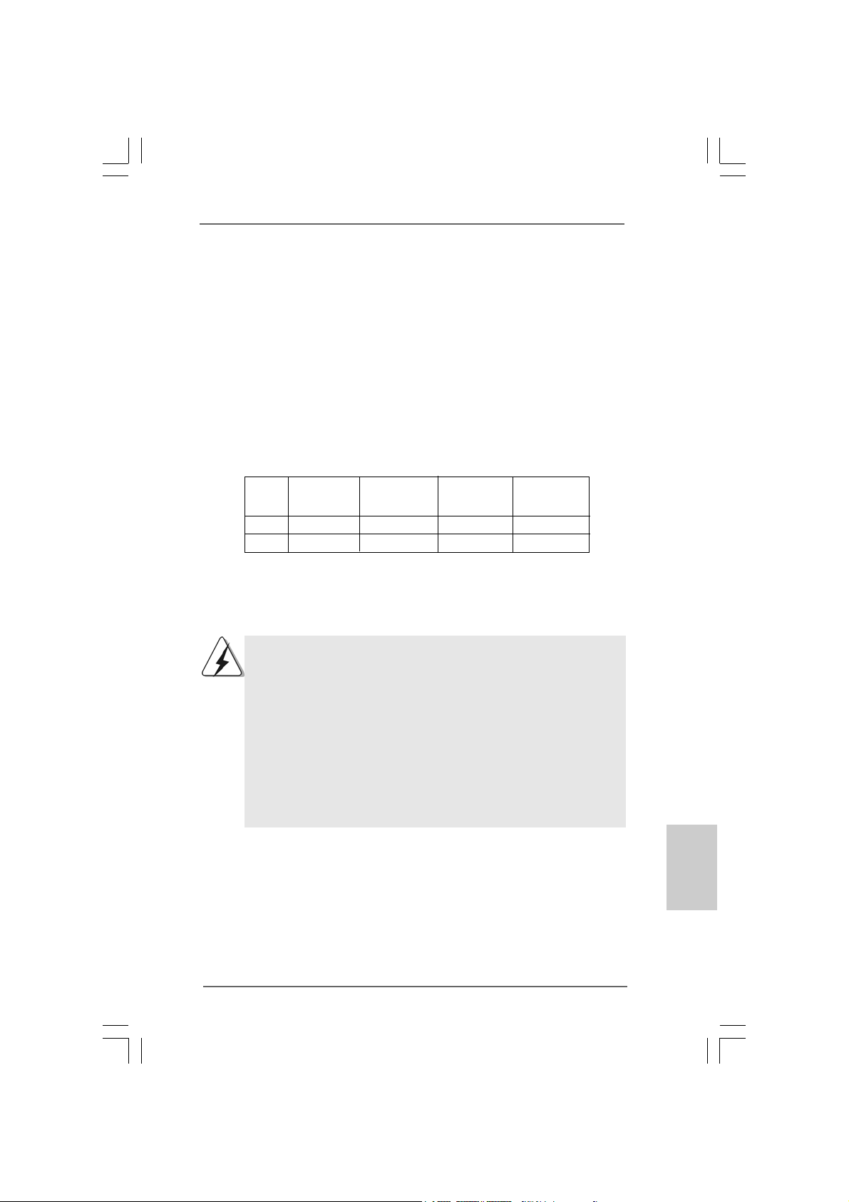
This motherboard provides four 240-pin DDR3 (Double Data Rate 3) DIMM slots,
and supports Dual Channel Memory Technology. For dual channel configuration,
you always need to install identical (the same brand, speed, size and chiptype) DDR3 DIMM pair in the slots of the same color. In other words, you have to
install identical DDR3 DIMM pair in Dual Channel (DDR3_A1 and DDR3_B1;
white slots; see p.2 No.5), so that Dual Channel Memory Technology can be
activated. This motherboard also allows you to install four DDR3 DIMMs for dual
channel configuration, and please install identical DDR3 DIMMs in all four slots.
You may refer to the Dual Channel Memory Configuration Table below.
Dual Channel Memory Configurations
DDR3_A2 DDR3_A1 DDR3_B2 DDR3_B1
(Blue Slot) (White Slot) (Blue Slot) (White Slot)
(1) - Populated - Populated
(2)* Populated Populated Populated Populated
* For the configuration (2), please install identical DDR3 DIMMs in all four
slots.
1. If you want to install two memory modules, for optimal compatibility
and reliability, it is recommended to install them in the slots of the
same color. In other words, install them either in the set of white slots
(DDR3_A1 and DDR3_B1).
2. If only one memory module or three memory modules are installed
in the DDR3 DIMM slots on this motherboard, it is unable to activate
the Dual Channel Memory Technology.
3. It is not allowed to install a DDR or DDR2 memory module into
DDR3 slot;otherwise, this motherboard and DIMM may be damaged.
4. Please install the memory module into the white slot (DDR3_B1) for
the first priority.
ASRock P55 Pro Motherboard
1313
13
1313
EnglishEnglish
EnglishEnglish
English
Page 14
Installing a DIMMInstalling a DIMM
Installing a DIMM
Installing a DIMMInstalling a DIMM
Please make sure to disconnect power supply before adding or removing
DIMMs or the system components.
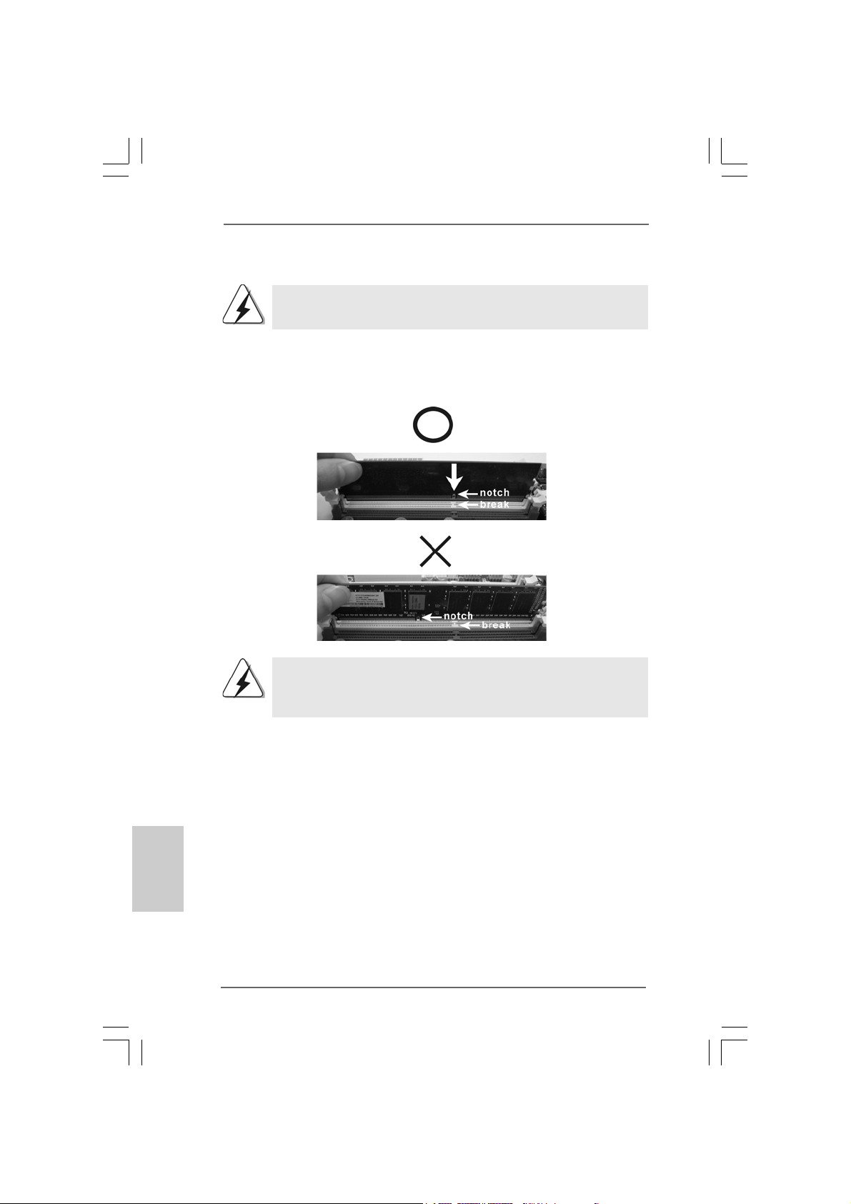
Step 1. Unlock a DIMM slot by pre ssing the retaining cli ps outward.
Step 2. Align a DIMM on the slot such that the notch on the DIMM matche s the brea k
on the slot.
The DIMM only fits in one correct orientation. It will cause permanent
damage to the motherboard and the DIMM if you force the DIMM into the slot
at incorrect orientation.
English
EnglishEnglish
EnglishEnglish
1414
14
1414
Step 3. Firmly insert the DIMM into the slot until the retaining clips at both ends fully
sna p back in place and the DIMM is properly seated.
ASRock P55 Pro Motherboard
Page 15
2.4 Expansion Slots (PCI and PCI Express Slots)2.4 Expansion Slots (PCI and PCI Express Slots)
2.4 Expansion Slots (PCI and PCI Express Slots)
2.4 Expansion Slots (PCI and PCI Express Slots)2.4 Expansion Slots (PCI and PCI Express Slots)
There are 2 PCI slots and 4 PCI Express slots on this motherboard.
PCI slots: PCI slots are used to install expansion cards that have the 32-bit PCI
interface.
PCIE slots:
PCIE1 / PCIE3 (PCIE x1 slot; White) is used for PCI Express cards with
x1 lane width cards, such as Gigabit LAN card, SATA2 card, etc.
PCIE2 (PCIE x16 slot; Blue) is used for PCI Express x16 lane width
graphics cards, or used to install PCI Express graphics cards to
support CrossFireXTM function.
PCIE4 (PCIE x16 slot; Orange) is used for PCI Express x1 lane width
cards, such as Gigabit LAN card, SATA2 card, etc., or used to install
PCI Express graphics cards to support CrossFireXTM function.
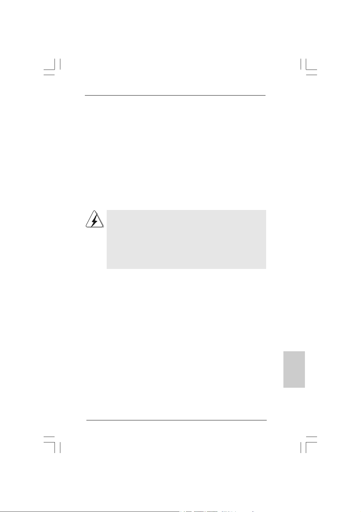
1. In single VGA card mode, it is recommended to install a PCI Express
x16 graphics card on PCIE2 slot.
2. In CrossFireXTM mode, please install PCI Express x16 graphics cards
on PCIE2 and PCIE4 slots. Therefore, PCIE2 slot will work at x16
bandwidth while PCIE4 slot will work at x4 bandwidth.
3. Please connect a chassis fan to motherboard chassis fan connector
(CHA_FAN1 or CHA_FAN2) when using multiple graphics cards for
better thermal environment.
Installing an expansion cardInstalling an expansion card
Installing an expansion card
Installing an expansion cardInstalling an expansion card
Step 1. Before installing the expansion card, please make sure that the power
supply is switched off or the power cord is unplugged. Please read the
documentation of the expansion card and make necessary hardware
settings for the card before you start the installation.
Step 2. Remove the system unit cover (if your motherboard is already installed in
a chassis).
Step 3. Remove the bracket facing the slot that you intend to use. Keep the
screws for later use.
Step 4. Align the card connector with the slot and press firmly until the card is
completely seated on the slot.
Step 5. Fasten the card to the chassis with screws.
Step 6. Replace the system cover.
EnglishEnglish
EnglishEnglish
English
ASRock P55 Pro Motherboard
1515
15
1515
Page 16
TMTM
TM
2.52.5
CrossFireXCrossFireX
2.5
CrossFireX
2.52.5
CrossFireXCrossFireX
GuideGuide
Guide
GuideGuide
This motherboard supports CrossFireXTM and Quad CrossFireXTM feature.
CrossFireXTM technology offers the most advantageous means available of combining
multiple high performance Graphics Processing Units (GPU) in a single PC. Combining
a range of different operating modes with intelligent software design and an innovative
interconnect mechanism, CrossFireXTM enables the highest possible level of
performance and image quality in any 3D application. Currently CrossFireXTM feature
is supported with Windows® XP with Service Pack 2 and VistaTM OS. Quad
CrossFireX
AMD website for ATITM CrossFireXTM driver updates.
2.5.1 Graphics Cards Setup2.5.1 Graphics Cards Setup
2.5.1 Graphics Cards Setup
2.5.1 Graphics Cards Setup2.5.1 Graphics Cards Setup
TM
feature are supported with Windows® VistaTM OS only. Please check
1. If a customer incorrectly configures their system they will not see the
performance benefits of CrossFireXTM. All three CrossFireXTM components, a
CrossFireXTM Ready graphics card, a CrossFireXTM Ready motherboard and a
CrossFireXTM Edition co-processor graphics card, must be installed correctly to
benefit from the CrossFireXTM multi-GPU platform.
2. If you pair a 12-pipe CrossFireXTM Edition card with a 16-pipe card, both cards
will operate as 12-pipe cards while in CrossFireXTM mode.
TMTM
and Quad CrossFireX and Quad CrossFireX
and Quad CrossFireX
and Quad CrossFireX and Quad CrossFireX
TMTM
TM
TMTM
Operation Operation
Operation
Operation Operation
English
EnglishEnglish
EnglishEnglish
1616
16
1616
Different CrossFireXTM cards may require different methods to enable CrossFireX
feature. In below procedures, we use Radeon HD 3870 as the example graphics card.
For other CrossFireXTM cards that ATITM has released or will release in the future, please
refer to ATITM graphics card manuals for detailed installation guide.
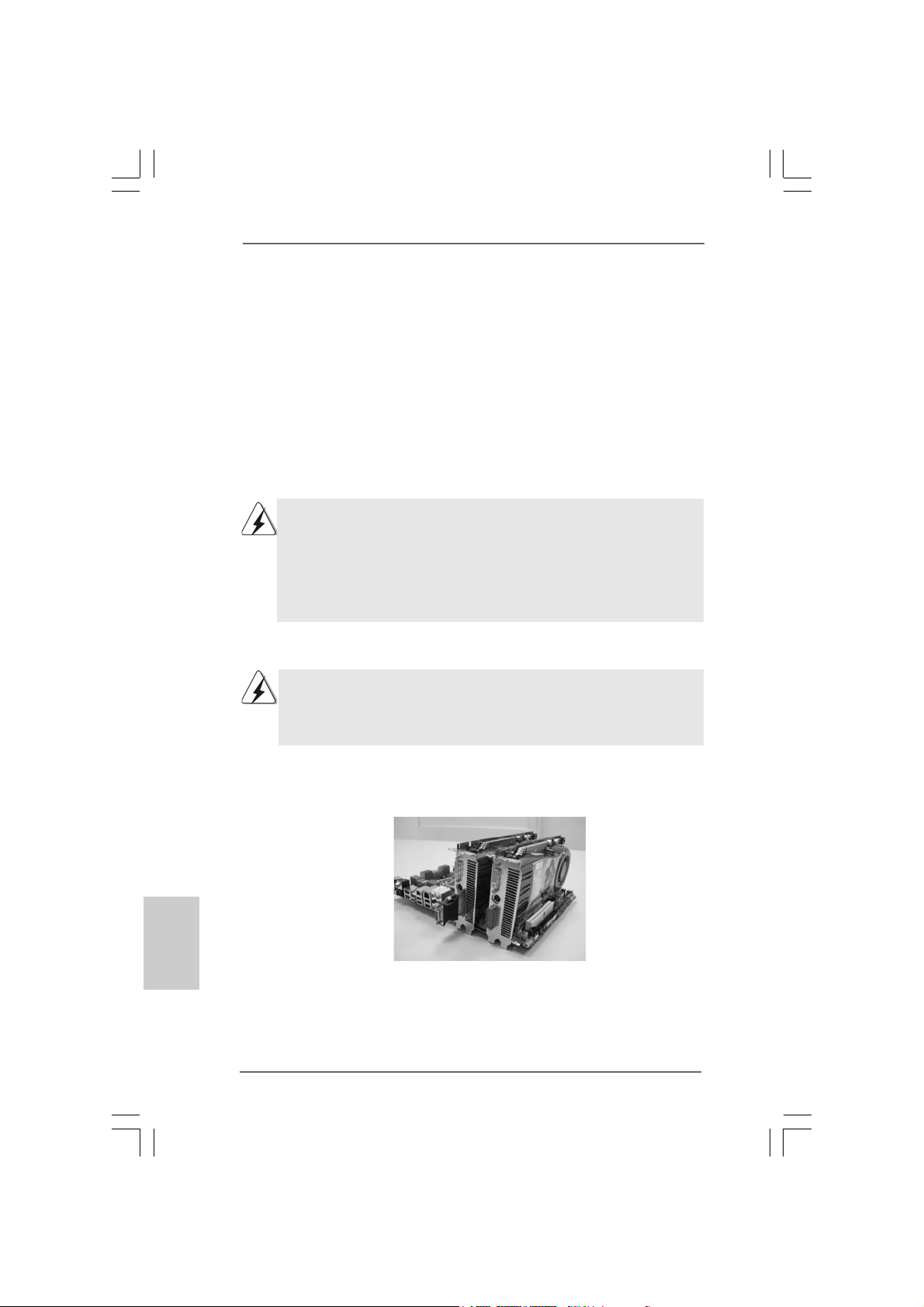
Step 1. Insert one Radeon graphics card into PCIE2 slot and the other Radeon
graphics card to PCIE4 slot. Make sure that the cards are properly seated
on the slots.
ASRock P55 Pro Motherboard
TM
Page 17
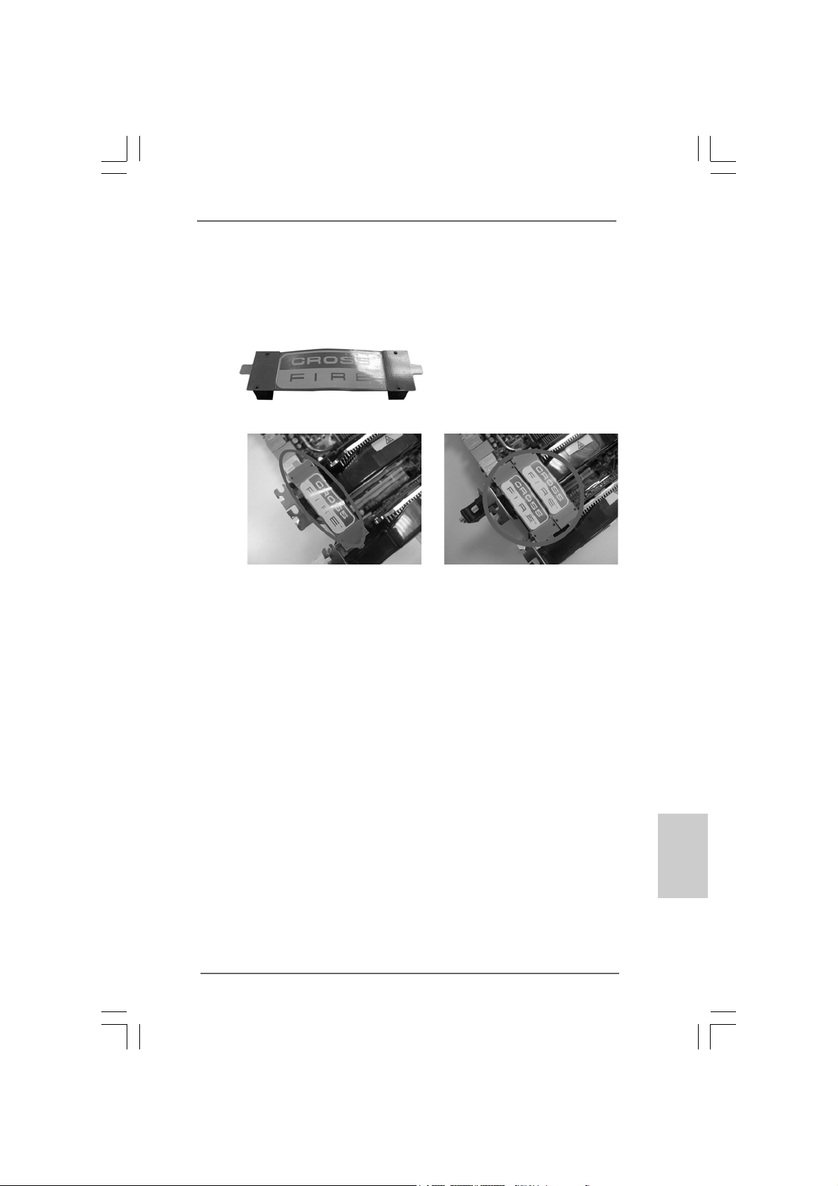
Step 2. Connect two Radeon graphics cards by installing CrossFire Bridge on
CrossFire Bridge Interconnects on the top of Radeon graphics cards.
(CrossFire Bridge is provided with the graphics card you purchase, not
bundled with this motherboard. Please refer to your graphics card vendor
for details.)
CrossFire Bridge
or
Step 2. Connect the DVI monitor cable to the DVI connector on the Radeon graphics
card on PCIE2 slot. (You may use the DVI to D-Sub adapter to convert the
DVI connector to D-Sub interface, and then connect the D-Sub monitor
cable to the DVI to D-Sub adapter.)
ASRock P55 Pro Motherboard
1717
17
1717
EnglishEnglish
EnglishEnglish
English
Page 18
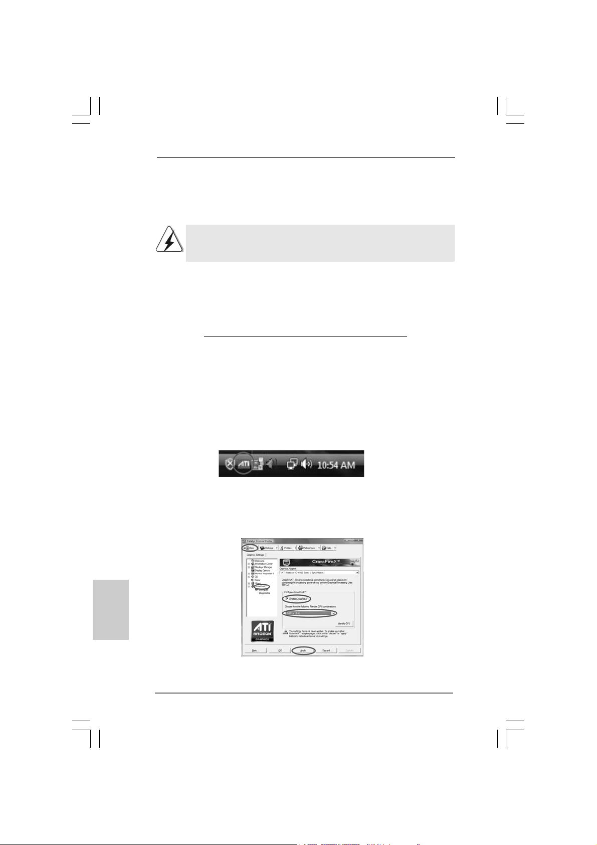
2.5.2 Driver Installation and Setup2.5.2 Driver Installation and Setup
2.5.2 Driver Installation and Setup
2.5.2 Driver Installation and Setup2.5.2 Driver Installation and Setup
Step 1. Power on your computer and boot into OS.
Step 2. Remove the A TITM driver if you have any VGA driver installed in your system.
The Catalyst Uninstaller is an optional download. We recommend using this
utility to uninstall any previously installed Catalyst drivers prior to installation.
Please check AMD website for ATITM driver updates.
Step 3. Install the required drivers to your system.
For Windows® XP OS:
A. ATITM recommends Windows® XP Service Pack 2 or higher to be
installed (If you have Windows® XP Service Pack 2 or higher installed
in your system, there is no need to download it again):
http://www.microsoft.com/windowsxp/sp2/default.mspx
B. You must have Microsoft .NET Framework installed prior to
downloading and installing the CATALYST Control Center. Please
check Microsoft website for details.
For Windows® VistaTM OS:
Install the CA TALYST Control Center. Please check AMD website f or details.
Step 4. Restart your computer.
Step 5. Install the VGA card drivers to your system, and restart your computer.
Then you will find “ATI Catalyst Control Center” on your Windows® taskbar.
(Driver Version: 8-12_vista32_dd_ccc_wdm_enu_72275.exe)
English
EnglishEnglish
EnglishEnglish
1818
18
1818
ATI Catalyst Control Center
Step 6. Double-click “ATI Catalyst Control Center”. Click “View”, select
“CrossFireXTM”, and then check the item “Enable CrossFireXTM”. Select the
option according to the total GPU number on the Radeon graphics cards.
Click “Apply”.
ASRock P55 Pro Motherboard
Page 19
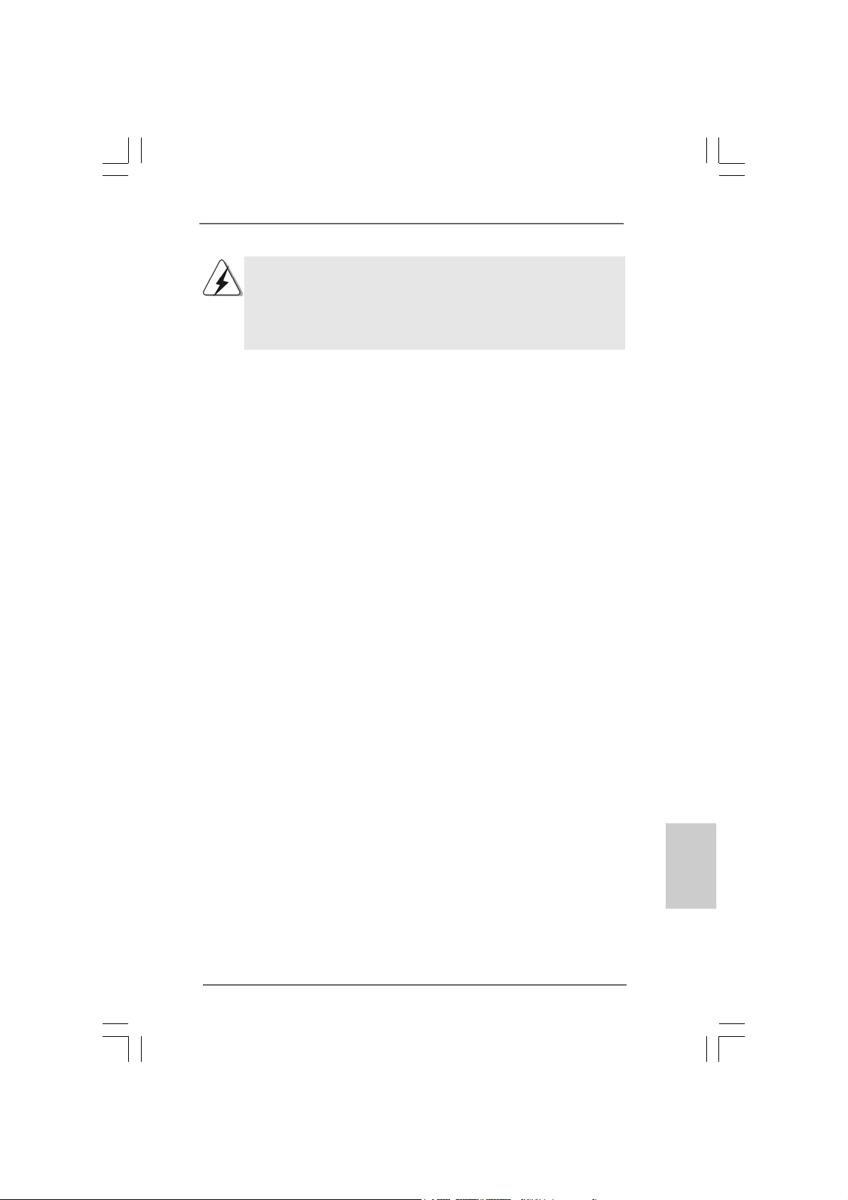
Although you have selected the option “Enable CrossFireTM”, the CrossFireX
function may not work actually. Your computer will automatically reboot. After
restarting your computer, please confirm whether the option “Enable CrossFireTM”
in “ATI Catalyst Control Center” is selected or not; if not, please select it again,
and then you are able to enjoy the benefit of CrossFireX
TM
feature.
TM
Step 7. You can freely enjoy the benefit of CrossFireXTM or Quad CrossFireX
feature.
* CrossFireXTM appearing here is a registered trademark of ATITM Technologies Inc., and is
used only for identification or explanation and to the owners’ benefit, without intent to infringe.
* For further information of ATITM CrossFireXTM technology, please check AMD website for
updates and details.
TM
ASRock P55 Pro Motherboard
1919
19
1919
EnglishEnglish
EnglishEnglish
English
Page 20
2.6 Surround Display Feature2.6 Surround Display Feature
2.6 Surround Display Feature
2.6 Surround Display Feature2.6 Surround Display Feature
This motherboard supports Surround Display upgrade. With the external add-on PCI
Express V GA cards, you can easily enjoy the benefits of Surround Display feature. For
the detailed instruction, plea se refer to the document at the f ollowing path in the
Support CD:
..\ Surround Display Information
2.7 Jumpers Setup2.7 Jumpers Setup
2.7 Jumpers Setup
2.7 Jumpers Setup2.7 Jumpers Setup
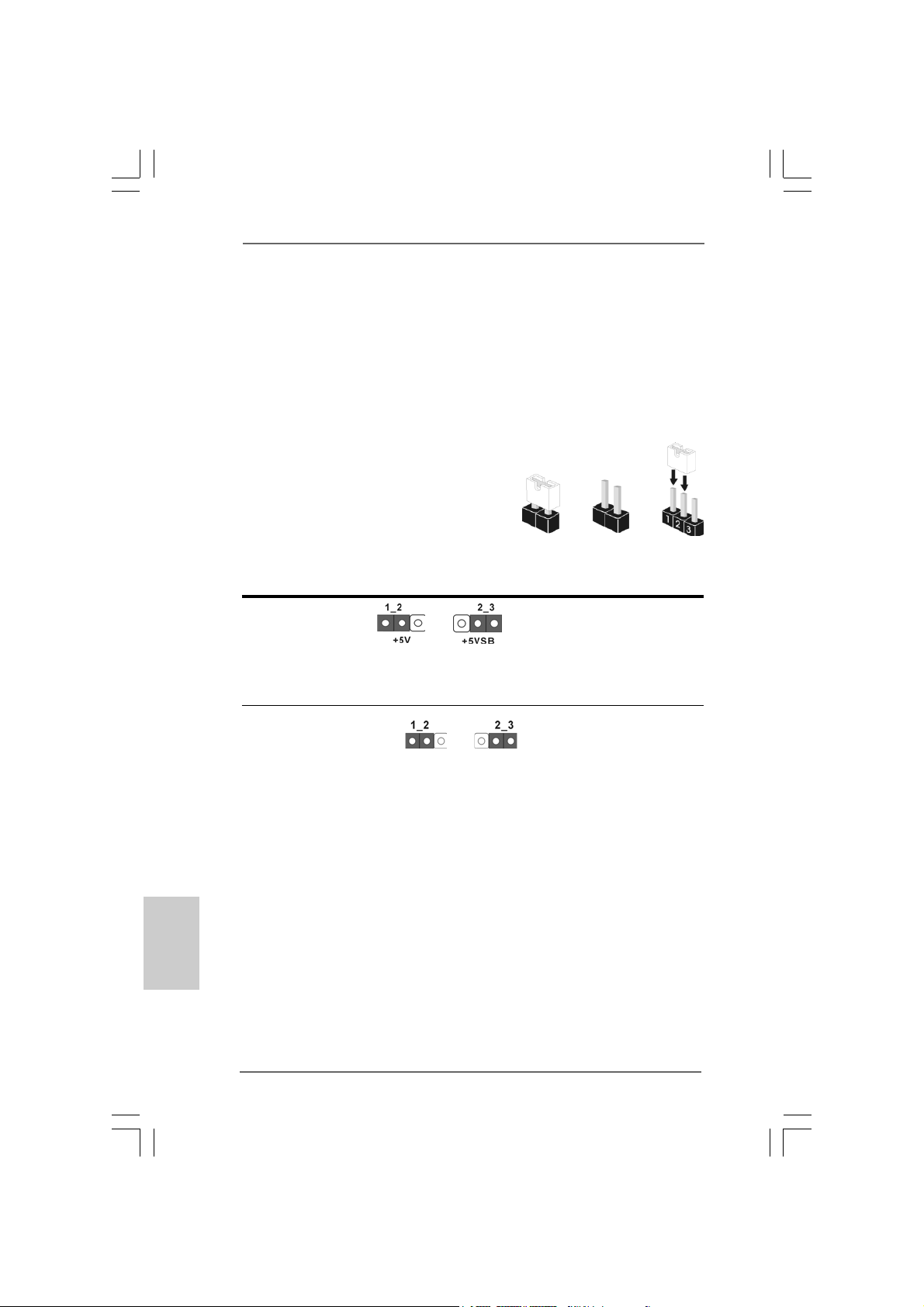
The illustration shows how jumpers are
setup. When the jumper cap is placed on
pins, the jumper is “Short”. If no jumper cap
is placed on pins, the jumper is “Open”. The
illustration shows a 3-pin jumper whose pin1
and pin2 are “Short” when jumper cap is
placed on these 2 pins.
Jumper Setting Description
PS2_USB_PWR1 Short pin2, pin3 to enable
(see p.2 No. 1) +5VSB (standby) for PS/2
Note: To select +5VSB, it requires 2 Amp and higher sta ndby current provided by power
supply.
Clear CMOS Jumper
(CLRCMOS1)
(see p.2 No. 15)
Clear CMOSDefault
Short Open
or USB wake up events.
English
EnglishEnglish
EnglishEnglish
2020
20
2020
Note: CLRCMOS1 allows you to clear the data in CMOS. The data in CMOS includes
system setup information such as system password, date, time, and system
setup parameters. To clear and reset the system parameters to default setup,
please turn of f the computer and unplug the power cord from the power supply.
After waiting for 15 seconds, use a jumper ca p to short pin2 and pin3 on CLRCMOS1
for 5 seconds. However , please do not clear the CMOS right after you update the
BIOS. If you need to clear the CMOS when you just finish updating the BIOS, you
must boot up the system first, and then shut it down before you do the clearCMOS action.
ASRock P55 Pro Motherboard
Page 21
2.8 Onboard Headers and Connectors2.8 Onboard Headers and Connectors
2.8 Onboard Headers and Connectors
2.8 Onboard Headers and Connectors2.8 Onboard Headers and Connectors
Onboard headers and connectors are NOT jumpers. Do NOT place
jumper caps over these headers and connectors. Placing jumper caps
over the headers and connectors will cause permanent damage of the
motherboard!
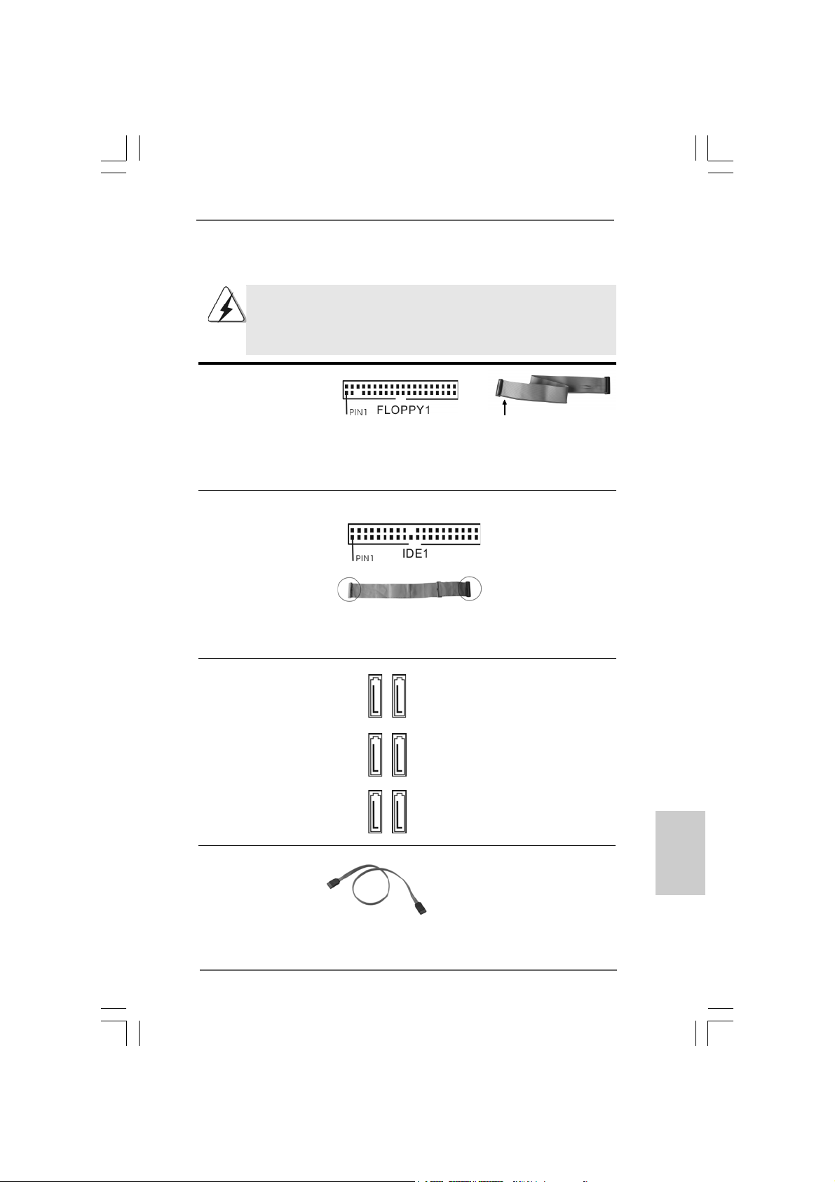
FDD connector
(33-pin FLOPPY1)
(see p.2 No. 27)
the red-striped side to Pin1
Note: Make sure the red-striped side of the cable is plugged into Pin1 side of the
connector.
Primary IDE connector (Blue)
(39-pin IDE1, see p.2 No. 14)
connect the blue end
to the motherboard
connect the black end
to the IDE devices
80-conductor ATA 66/100/133 cable
Note: P l e ase re f e r t o t h e i nstruction of your IDE device vendor for the details.
Serial ATAII Connectors These six Serial ATAII (SATAII)
(SAT AII_1_2: connectors support SATA data
see p.2, No. 9) cables for internal storage
(SAT AII_3_4: devices. The current SATAII
see p.2, No. 10) interface allows up to 3.0 Gb/s
(SAT AII_5_6: data transfer rate.
see p.2, No. 1 1)
SAT AII_5_6 SA T AII_3_4 SA T AII_1_2
Serial A TA (SATA) Either end of the SATA data cable
Data Cable can be connected to the SATA /
(Optional) SATAII hard disk or the SATAII
connector on this motherboard.
ASRock P55 Pro Motherboard
2121
21
2121
EnglishEnglish
EnglishEnglish
English
Page 22
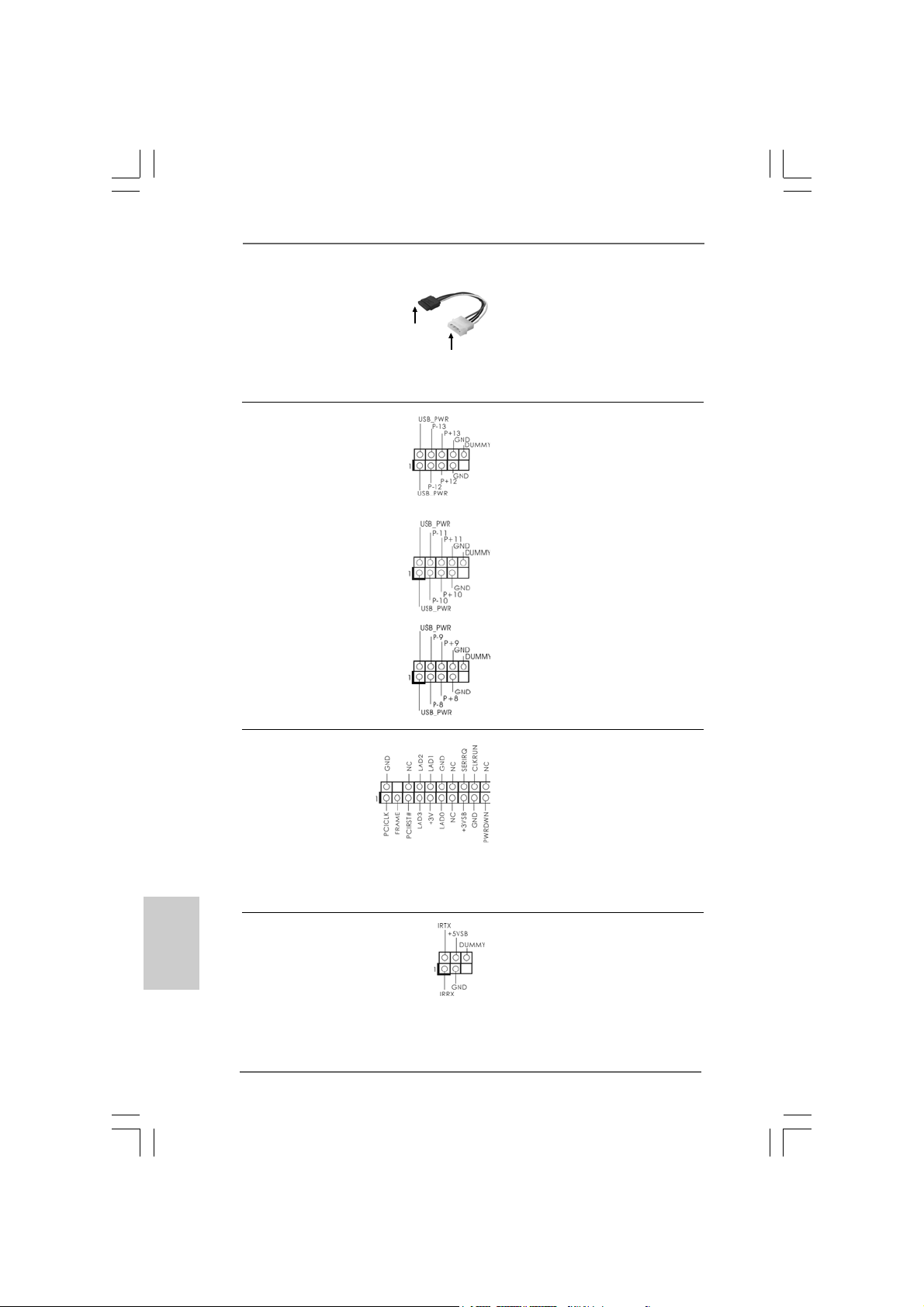
Serial ATA (SATA) Please connect the black end of
Power Cable SATA power cable to the power
(Optional) connector on each drive. Then
connect to the SAT A
HDD power connector
connect to the
power supply
connect the white end of SATA
power cable to the power
connector of the power supply.
USB 2.0 Headers Besides six default USB 2.0
(9-pin USB12_13) ports on the I/O panel, there are
(see p.2 No. 23) three USB 2.0 headers on this
motherboard. Each USB 2.0
header can support two USB
2.0 ports.
(9-pin USB10_11)
(see p.2 No. 24)
(9-pin USB8_9)
(see p.2 No. 25)
English
EnglishEnglish
EnglishEnglish
2222
22
2222
TPM Header This connector supports a
(19-pin TPM1) Trusted Platform Module (TPM)
(see p.2 No. 19) system, which can securely
store keys, digital certificates,
passwords, and data. A TPM
system also helps enhance
network security, protects
digital identities, and ensures
platform integrity.
Infrared Module Header This header supports an optional
(5-pin IR1) wireless transmitting and
(see p.2 No. 21) receiving infrared module.
ASRock P55 Pro Motherboard
Page 23
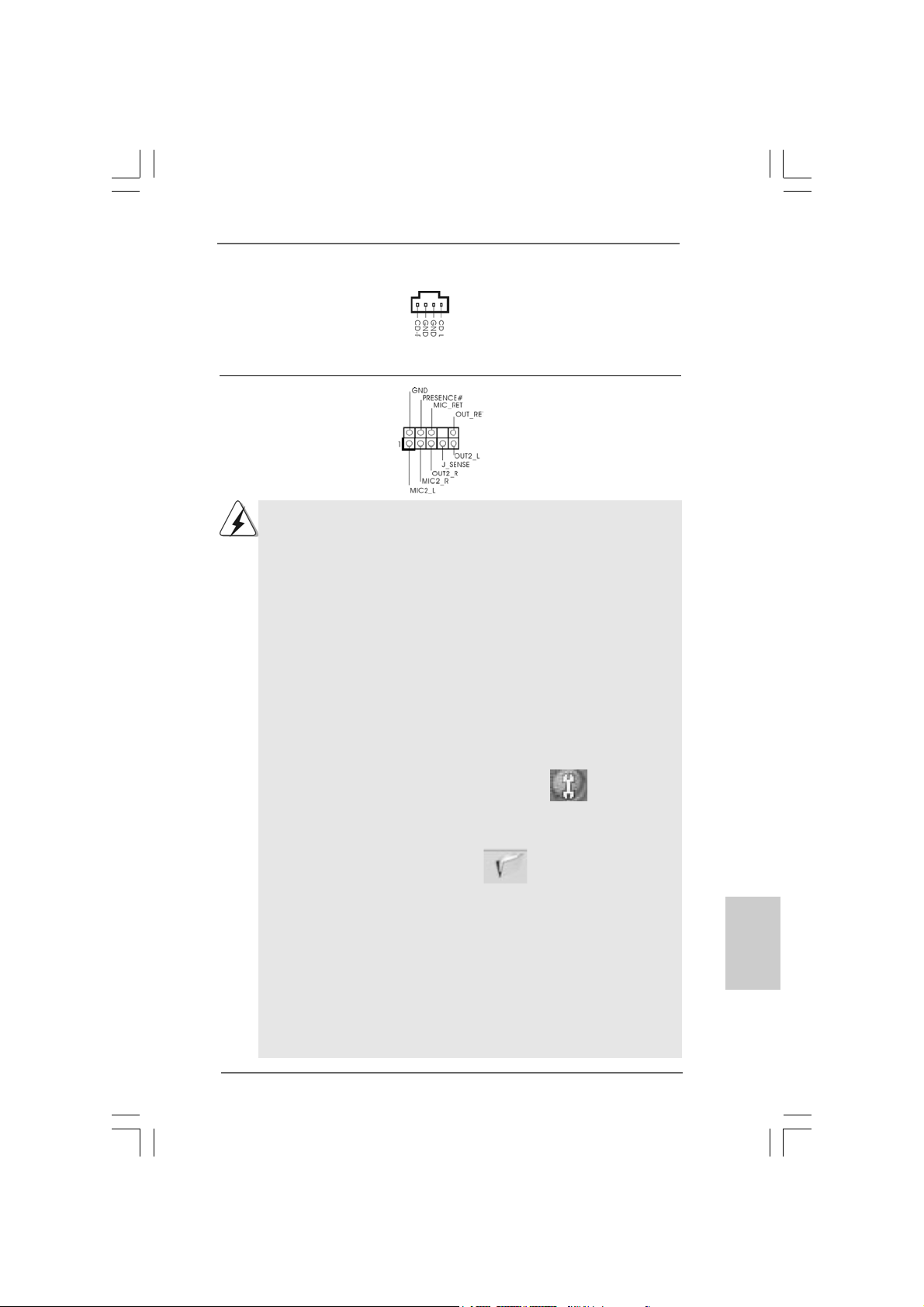
Internal Audio Connectors This connector allows you
(4-pin CD1) to receive stereo audio input
(CD1: see p.2 No. 31) from sound sources such as
CD1
a CD-ROM, D VD-ROM, TV
tuner card, or MPEG card.
Front Panel Audio Header This is an interface for front
(9-pin HD_AUDIO1) panel audio cable that allows
(see p.2 No. 30) convenient connection and
control of audio devices.
1. High Definition Audio supports Jack Sensing, but the panel wire on
the chassis must support HDA to function correctly. Please follow the
instruction in our manual and chassis manual to install your system.
2. If you use AC’97 audio panel, please install it to the front panel audio
header as below:
A. Connect Mic_IN (MIC) to MIC2_L.
B. Connect Audio_R (RIN) to OUT2_R and Audio_L (LIN) to OUT2_L.
C. Connect Ground (GND) to Ground (GND).
D. MIC_RET and OUT_RET are for HD audio panel only. You don’t
need to connect them for AC’97 audio panel.
E. Enter BIOS Setup Utility. Enter Advanced Settings, and then select
Chipset Configuration. Set the Front Panel Control option from
[Auto] to [Enabled].
F. Enter Windows system. Click the icon on the lower right hand
taskbar to enter Realtek HD Audio Manager.
For Windows® XP / XP 64-bit OS:
Click “Audio I/O”, select “Connector Settings” , choose
“Disable front panel jack detection”, and save the change by
clicking “OK”.
For Windows® VistaTM / VistaTM 64-bit OS:
Click the right-top “Folder” icon , choose “Disable front
panel jack detection”, and save the change by clicking “OK”.
G. To activate the front mic.
For Windows® XP / XP 64-bit OS:
Please select “Front Mic” as default record device.
If you want to hear your voice through front mic, please deselect "Mute"
icon in “Front Mic” of “Playback” portion.
For Windows® VistaTM / VistaTM 64-bit OS:
Go to the "Front Mic" Tab in the Realtek Control panel.
Click "Set Default Device" to make the Front Mic as the default record
device.
ASRock P55 Pro Motherboard
2323
23
2323
EnglishEnglish
EnglishEnglish
English
Page 24
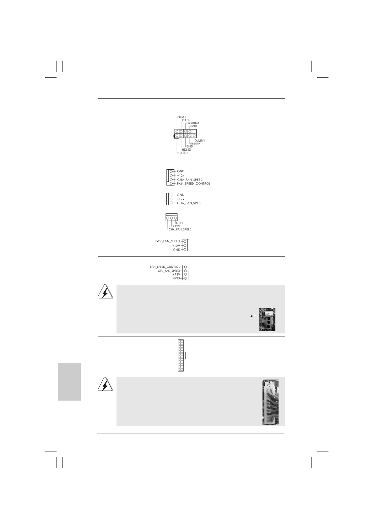
System Panel Header This header accommodates
(9-pin PANEL1) several system front panel
(see p.2 No. 22) functions.
Chassis and Power Fan Connectors Please connect the fan cables
(4-pin CHA_FAN1) to the fan connectors and
(see p.2 No. 7) match the black wire to the
ground pin.
(3-pin CHA_FAN2)
(see p.2 No. 8)
(3-pin CHA_FAN3)
(see p.2 No. 12)
(3-pin PWR_FAN1)
(see p.2 No. 38)
English
EnglishEnglish
EnglishEnglish
2424
24
2424
CPU Fan Connector Please connect a CPU fan cable
(4-pin CPU_FAN1) to this connector and match
(see p.2 No. 37) the black wire to the ground pin.
4
3
2
1
Though this motherboard provides 4-Pin CPU fan (Quiet Fan) support, the 3-Pin
CPU fan still can work successfully even without the fan speed control function.
If you plan to connect the 3-Pin CPU fan to the CPU fan connector on this
motherboard, please connect it to Pin 1-3.
Pin 1-3 Connected
3-Pin Fan Installation
ATX Power Connector Please connect an ATX power
(24-pin ATXPW R1) supply to this connector.
(see p.2, No. 6)
Though this motherboard provides 24-pin ATX power connector,
12 124
13
12
24
it can still work if you adopt a traditional 20-pin ATX power supply.
To use the 20-pin ATX power supply, please plug your
power supply along with Pin 1 and Pin 13.
20-Pin A TX Power Supply Installation
1
13
ASRock P55 Pro Motherboard
Page 25
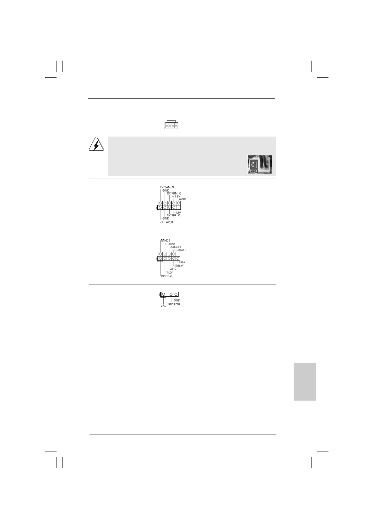
ATX 12V Power Connector Please connect an ATX 12V
(8-pin A TX12V1) power supply to this connector.
(see p.2 No. 2)
Though this motherboard provides 8-pin ATX 12V power connector, it can still work
if you adopt a traditional 4-pin ATX 12V power supply. To use the 4-pin ATX power
supply, please plug your power supply along with Pin 1 and Pin 5.
8 5
4 1
8 5
4-Pin ATX 12V Power Supply Installation
4 1
IEEE 1394 Header Besides one default IEEE 1394
(9-pin FRONT_1394) port on the I/O panel, there is one
(see p.2 No. 26) IEEE 1394 header
(FRONT_1394) on this
motherboard. This IEEE 1394
header cansupport one IEEE
1394 port.
Serial port Header This COM1 header supports a
(9-pin COM1) serial port module.
(see p.2 No.28)
HDMI_SPDIF Header HDMI_SPDIF header, providing
(3-pin HDMI_SPDIF1) SPDIF audio output to HDMI V GA
(see p.2 No. 29) card, allows the system to
connect HDMI Digital TV/
projector/LCD devices. Please
connect the HDMI_SPDIF
connector of HDMI VGA card to
this header.
12
1
24
EnglishEnglish
EnglishEnglish
English
13
2525
25
2525
ASRock P55 Pro Motherboard
Page 26
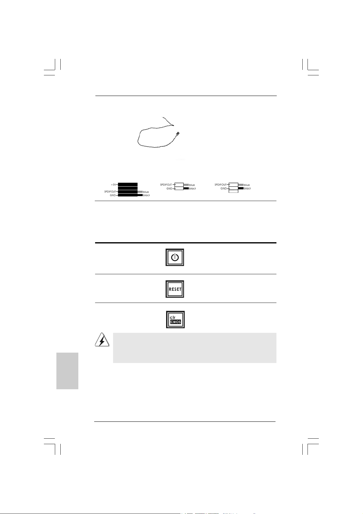
HDMI_SPDIF Cable Please connect the black end (A)
(Optional) of HDMI_SPDIF cable to the
C
B
A
HDMI_SPDIF header on the
motherboard. Then connect the
white end (B or C) of
HDMI_SPDIF cable to the
HDMI_SPDIF connector of HDMI
VGA card.
A. black end B. white end (2-pin) C. white end (3-pin)
2.9 Smart Switches2.9 Smart Switches
2.9 Smart Switches
2.9 Smart Switches2.9 Smart Switches
This motherboard has three smart switches: power switch, reset switch and
clear CMOS switch, allowing users to quickly turn on/off or reset the system or
clear the CMOS values.
Power Switch Power Switch is a smart switch,
(PWRBTN) allowing users to quickly turn
(see p.2 No. 20) on/off the system.
Reset Switch Reset Switch is a smart switch,
(RSTBTN) allowing users to quickly reset
(see p.2 No. 18) the system.
English
EnglishEnglish
EnglishEnglish
2626
26
2626
Clear CMOS Switch Clear CMOS Switch is a smart
(CLRCBTN) switch, allowing users to quickly
(see p.3 No. 17) clear the CMOS values
You are not allowed to use Clear CMOS switch function if you set up the system
password. If you want to clear the CMOS values, please clean your system
password in advance or refer to page 20 “Clear CMOS jumper” description
instead.
ASRock P55 Pro Motherboard
Page 27
2.10 Dr. Debug2.10 Dr. Debug
2.10 Dr. Debug
2.10 Dr. Debug2.10 Dr. Debug
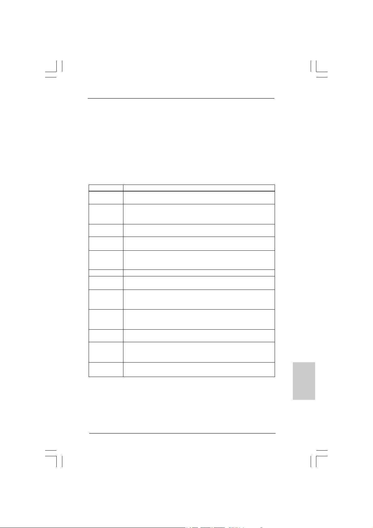
Dr. Debug is used to provide code information, which makes troubleshooting even
easier. Please see the diagrams below for reading the Dr. Debug codes.
The Bootblock initialization code sets up the chipset, memory and other
components before system memory is available. The following table describes the
type of checkpoints that may occur during the bootblock initialization portion of the
BIOS:
Checkpoint Description
Before D1 Early chipset initialization is done. Early super I/O initialization is done
D1 Perform keyboard controller BAT test. Check if waking up from power
D0 Go to flat mode with 4GB limit and GA20 enabled. Verify the bootblock
D2 Disable CACHE before memory detection. Execute full memory sizing
D3 If memory sizing module not executed, start memory refresh and do
D4 Test base 512KB memory. Adjust policies and cache first 8MB. Set stack.
D5 Bootblock code is copied from ROM to lower system memory and control
D6 Both key sequence and OEM specific method is checked to determine if
D7 Restore CPUID value back into register. The Bootblock-Runtime interface
D8 The Runtime module is uncompressed into memory. CPUID information is
D9 Store the Uncompressed pointer for future use in PMM. Copying Main BIOS
DA Restore CPUID value back into register. Give control to BIOS POST
including RTC and keyboard controller. NMI is disabled.
management suspend state. Save power-on CPUID value in scratch
CMOS.
checksum.
module. Verify that flat mode is enabled.
memory sizing in Bootblock code. Do additional chipset initialization.
Re-enable CACHE. Verify that flat mode is enabled.
is given to it. BIOS now executes out of RAM.
BIOS recovery is forced. Main BIOS checksum is tested. If BIOS recovery
is necessary, control flows to checkpoint E0.
module is moved to system memory and control is given to it. Determine
whether to execute serial flash.
stored in memory.
into memory. Leaves all RAM below 1MB Read-Write including E000 and
F000 shadow area s but closing SMRAM.
(ExecutePOSTKernel).
ASRock P55 Pro Motherboard
2727
27
2727
EnglishEnglish
EnglishEnglish
English
Page 28
English
EnglishEnglish
EnglishEnglish
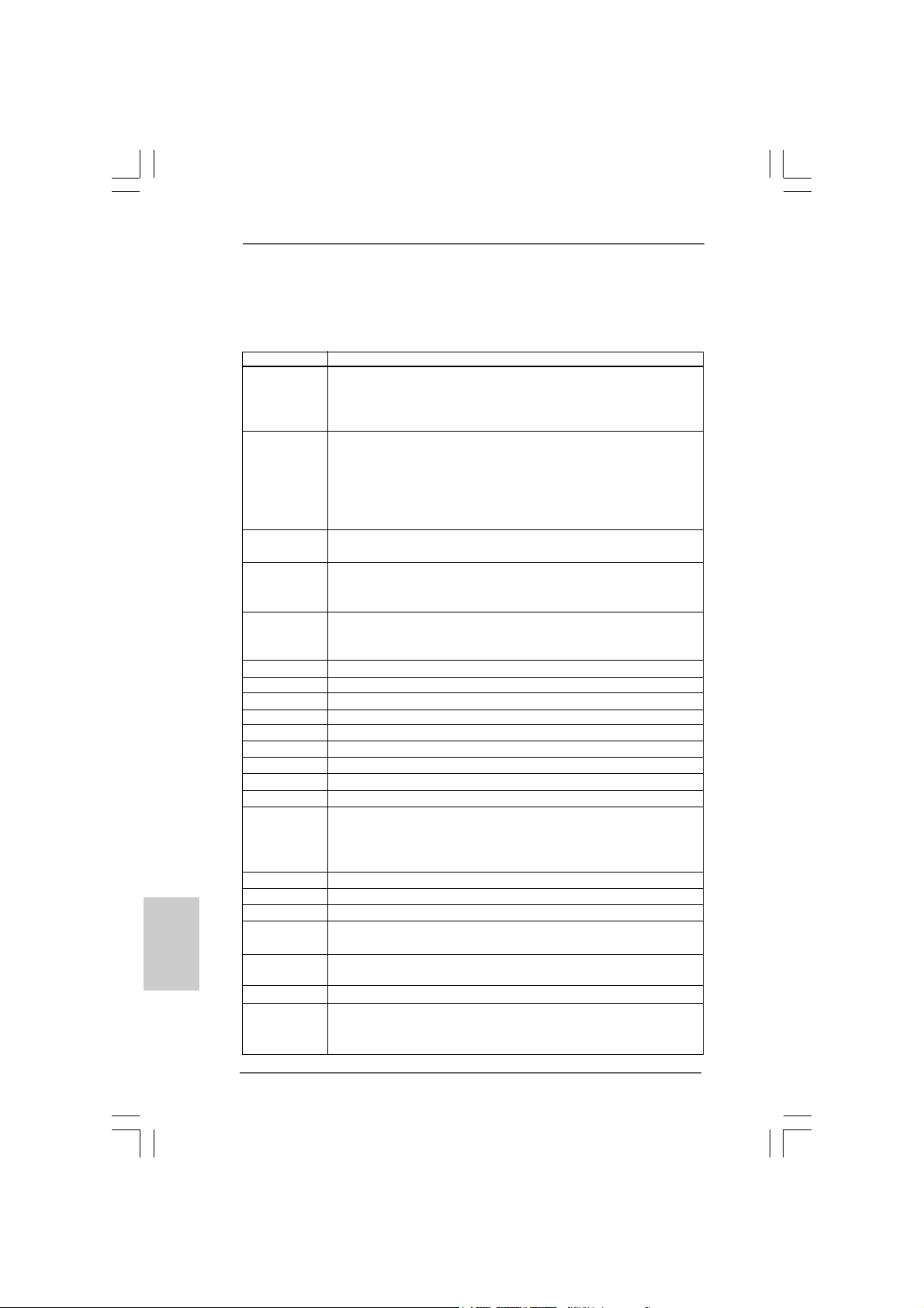
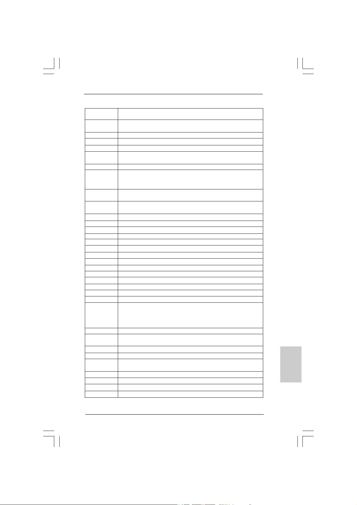
The POST code checkpoints are the largest set of checkpoints during
the BIOS pre-boot process. The following table describes the type of
checkpoints that may occur during the POST portion of the BIOS:
Checkpoint Description
03 Disable NMI, Parity, video for EGA, and DMA controllers.
Initialize BIOS, POST, Runtime data area. Also initialize BIOS
modules on POST entry and GPNV area. Initialized CMOS as
mentioned in the Kernel V ari able “wCMOSFlags.”
04 Check CMOS diagnostic byte to determine if battery power is OK and
CMOS checksum is OK. Verify CMOS checksum manually by reading
storage area. If the CMOS checksum is bad, update CMOS with power-on
default values and clear passwords. Initialize status register A.
Initializes data variables that are based on CMOS setup questions.
Initializes both the 8259 compatible PICs in the system
05 Initializes the interrupt controlling hardware (generally PIC) and interrupt
vector table.
06 Do R/W test to CH-2 count reg. Initialize CH-0 as system timer. Install the
POSTINT1Ch handler. Enable IRQ-0 in PIC for system timer interrupt.
Traps INT1Ch vector to “POSTINT1ChHandlerBlock.”
08 Initializes the CPU. The BAT test is being done on KBC. Program the
keyboard controller command byte is being done after Auto detection of
KB/MS using AMI KB-5.
C0 Early CPU Init Start — Disable Cache - Init Local APIC
C1 Set up boot strap proccessor Information
C2 Set up boot strap proccessor for POST
C5 Enumerate and set up application proccessors
C6 Re-enable cache for boot strap proccessor
C7 Early CPU Init Exit
0A Initializes the 8042 compatible Key Board Controller.
0B Detects the presence of PS/2 mouse.
0C Detects the presence of Keyboard in KBC port.
0E Testing and initialization of different Input Devices. Also, update the Kernel
Variables. Traps the INT09h vector, so that the POST INT09h handler gets
control for IRQ1. Uncompress all available language, BIOS logo, and Silent
logo modules.
13 Early POST initialization of chipset registers.
24 Uncompress and initialize any platform specific BIOS modules.
30 Initialize System Management Interrupt.
2A Initializes different devices through DIM.
See DIM Code Checkpoints section of document for more information.
2C Initializes different devices. Detects and initializes the video adapter
installed in the system that have optional ROMs.
2E Initializes all the output devices.
31 Allocate memory for ADM module and uncompress it. Give control to ADM
module for initialization. Initialize language and font modules for ADM.
Activate ADM module.
2828
28
2828
ASRock P55 Pro Motherboard
Page 29
33 Initializes the silent boot module. Set the window for displaying text
information.
37 Displaying sign-on message, CPU information, setup key message, and
any OEM specific information.
38 Initializes different devices through DIM.
39 Initializes DMAC-1 & DMAC-2.
3A Initialize RTC date/time.
3B Test for total memory installed in the system. Also, Check for DEL or ESC
keys to limit memory test. Display total memory in the system.
3C Mid POST initialization of chipset registers.
40 Detect different devices (Parallel ports, serial ports, and coprocessor in
CPU, etc.) successfully installed in the system and update the BDA,
EBDA, etc.
50 Programming the memory hole or any kind of implementation that needs an
adjustment in system RAM size if needed.
52 Updates CMOS memory size from memory found in memory test.
Allocates memory for Extended BIOS Data Area from base memory.
60 Initializes NUM-LOCK status and programs the KBD typematic rate.
75 Initialize Int-13 and prepare for IPL detection.
78 Initializes IPL devices controlled by BIOS and option ROMs.
7A Initializes remaining option ROMs.
7C Generate and write contents of ESCD in NVRam.
84 Log errors encountered during POST.
85 Display errors to the user and gets the user response for error.
87 Execute BIOS setup if needed / requested.
8C Late POST initialization of chipset registers.
8D Build ACPI tables (if ACPI is supported)
8E Program the peripheral parameters. Enable/Disable NMI as selected
90 Late POST initialization of system management interrupt.
A0 Check boot password if installed.
A1 Clean-up work needed before booting to OS.
A2 Takes care of runtime image preparation for different BIOS modules. Fill
the free area in F000h segment with 0FFh. Initializes the Microsoft IRQ
Routing Table. Prepares the runtime language module. Disables the system
configuration display if needed.
A4 Initialize runtime language module.
A7 Displays the system configuration screen if enabled. Initialize the CPU’s
before boot, which includes the programming of the MTRR’s.
A8 Prepare CPU for OS boot including final MTRR values.
A9 Wait for user input at config display if needed.
AA Uninstall POST INT1Ch vector and INT09h vector. Deinitializes the ADM
module.
AB Prepare BBS for Int 19 boot.
AC End of POST initialization of chipset registers.
B1 Save system context for ACPI.
00 Passes control to OS Loader (typically INT19h).
EnglishEnglish
EnglishEnglish
English
ASRock P55 Pro Motherboard
2929
29
2929
Page 30

2.112.11
Driver Installation Guide Driver Installation Guide
2.11
Driver Installation Guide
2.112.11
Driver Installation Guide Driver Installation Guide
To install the drivers to your system, please insert the support CD to your optical
drive first. Then, the drivers compatible to your system can be auto-detected and
listed on the support CD driver page. Please follow the order from up to bottom
side to install those required drivers. Therefore, the drivers you install can work
properly.
English
EnglishEnglish
EnglishEnglish
®®
®
2.122.12
Installing WindowsInstalling Windows
2.12
Installing Windows
2.122.12
Installing WindowsInstalling Windows
64-bit With RAID Functions64-bit With RAID Functions
64-bit With RAID Functions
64-bit With RAID Functions64-bit With RAID Functions
If you want to install Windows® XP / XP 64-bit / VistaTM / VistaTM 64-bit on your SATA /
SATAII HDDs with RAID functions, ple ase refer to the document at the following path in
the Support CD for detailed procedures:
..\ RAID Installation Guide
2.132.13
Installing WindowsInstalling Windows
2.13
Installing Windows
2.132.13
Installing WindowsInstalling Windows
64-bit Without RAID Functions64-bit Without RAID Functions
64-bit Without RAID Functions
64-bit Without RAID Functions64-bit Without RAID Functions
If you want to install Windows® XP / XP 64-bit / VistaTM / VistaTM 64-bit OS on your SATA
/ SATAII HDDs without RAID functions, ple a se follow below procedure s a ccording to the
OS you install.
2.13.1 Installing Windows2.13.1 Installing Windows
2.13.1 Installing Windows
2.13.1 Installing Windows2.13.1 Installing Windows
Functions Functions
Functions
Functions Functions
If you want to install Windows® XP / XP 64-bit OS on your SATA / SATAII HDDs
without RAID functions, please follow below steps.
Using SATA / SATAII HDDs without NCQ function
STEP 1: Set up BIOS.
A. Enter BIOS SETUP UTILITY Advanced screen Storage Configuration.
B. Set the option “SATAII Operation Mode” to [IDE].
STEP 2: Install Windows® XP / XP 64-bit OS on your system.
®®
XP / XP 64-bit / Vista XP / XP 64-bit / Vista
XP / XP 64-bit / Vista
XP / XP 64-bit / Vista XP / XP 64-bit / Vista
®®
®
®®
XP / XP 64-bit / Vista XP / XP 64-bit / Vista
XP / XP 64-bit / Vista
XP / XP 64-bit / Vista XP / XP 64-bit / Vista
®®
®
®®
XP / XP 64-bit Without RAID XP / XP 64-bit Without RAID
XP / XP 64-bit Without RAID
XP / XP 64-bit Without RAID XP / XP 64-bit Without RAID
TM TM
TM
TM TM
/ Vista/ Vista
/ Vista
/ Vista/ Vista
TM TM
TM
TM TM
/ Vista/ Vista
/ Vista
/ Vista/ Vista
TMTM
TM
TMTM
TMTM
TM
TMTM
3030
30
3030
ASRock P55 Pro Motherboard
Page 31

®®
®
OS)
TM
64-bit OS)
®®
2.13.2 Installing Windows2.13.2 Installing Windows
2.13.2 Installing Windows
2.13.2 Installing Windows2.13.2 Installing Windows
Without RAID Functions Without RAID Functions
Without RAID Functions
Without RAID Functions Without RAID Functions
If you want to install Windows® VistaTM / VistaTM 64-bit OS on your SATA / SATAII
HDDs without RAID functions, please follow below steps.
Using SATA / SATAII HDDs without NCQ function
STEP 1: Set up BIOS.
A. Enter BIOS SETUP UTILITY Advanced screen Storage Configuration.
B. Set the option “SATAII Operation Mode” to [IDE].
STEP 2: Install Windows® VistaTM / VistaTM 64-bit OS on your system.
Using SATA / SATAII HDDs with NCQ function
STEP 1: Set Up BIOS.
A. Enter BIOS SETUP UTILITY Advanced screen Storage Configuration.
B. Set the option “SATAII Operation Mode” to [AHCI].
STEP 2: Install Windows® VistaTM / VistaTM 64-bit OS on your system.
Insert the Windows® VistaTM / VistaTM 64-bit optical disk into the optical drive to boot
your system, and follow the instruction to install Windows® VistaTM / VistaTM 64-bit OS
on your system. When you see “Where do you want to install Windows?” page, ple ase
insert the ASRock Support CD into your optical drive, and click the “Load Driver” button
on the left on the bottom to load the Intel® AHCI drivers. Intel® AHCI drivers are in the
following path in our Support CD:
.. \ I386 (For Windows® Vista
.. \ AMD64 (For Windows® Vista
After that, please insert Windows® VistaTM / VistaTM 64-bit optical disk into the optical
drive again to continue the installation.
TM
Vista Vista
Vista
Vista Vista
TM TM
TM
TM TM
/ Vista/ Vista
/ Vista
/ Vista/ Vista
TMTM
TM
TMTM
64-bit 64-bit
64-bit
64-bit 64-bit
2.142.14
Untied Overclocking TUntied Overclocking T
2.14
Untied Overclocking T
2.142.14
Untied Overclocking TUntied Overclocking T
This motherboard supports Untied Overclocking Technology, which means during
overclocking, FSB enjoys better margin due to fixed PCI / PCIE buses. Before you
enable Untied Overclocking function, plea se enter “Overclock Mode” option of BIOS setup
to set the selection from [Auto] to [Manual]. Therefore, CPU FSB is untied during
overclocking, but PCI / PCIE buses are in the fixed mode so that FSB can operate under
a more stable overclocking environment.
Please refer to the warning on page 7 for the possible overclocking risk
before you apply Untied Overclocking Technology.
ASRock P55 Pro Motherboard
echnologyechnology
echnology
echnologyechnology
3131
31
3131
EnglishEnglish
EnglishEnglish
English
Page 32

3. BIOS Information3. BIOS Information
3. BIOS Information
3. BIOS Information3. BIOS Information
The Flash Memory on the motherboard stores BIOS Setup Utility. When you start up
the computer, please press <F2> during the Power-On-Self-Test (POST) to enter
BIOS Setup utility; otherwise, POST continues with its test routines. If you wish to
enter BIOS Setup after POST, please restart the system by pressing <Ctl> + <Alt> +
<Delete>, or pressing the reset button on the system chassis. The BIOS Setup
program is designed to be user-friendly. It is a menu-driven program, which allows
you to scroll through its various sub-menus and to select among the predetermined
choices. For the detailed information about BIOS Setup, please refer to the User
Manual (PDF file) contained in the Support CD.
English
EnglishEnglish
EnglishEnglish
4. Sof4. Sof
4. Sof
4. Sof4. Sof
This motherboard supports various Microsoft® Windows® operating systems: XP / XP
64-bit / VistaTM / Vista
contains necessary drivers and useful utilities that will enhance motherboard features.
To begin using the Support CD, insert the CD into your CD-ROM drive. It will display
the Main Menu automatically if “AUTORUN” is enabled in your computer. If the Main
Menu does not appear automatically, locate and double-click on the file “ASSETUP.
EXE” from the BIN folder in the Support CD to display the menus.
tware Supportware Suppor
tware Suppor
tware Supportware Suppor
TM
64-bit / Win7. The Support CD that came with the motherboard
t CD informationt CD information
t CD information
t CD informationt CD information
3232
32
3232
ASRock P55 Pro Motherboard
Page 33
1. Einführung1. Einführung
1. Einführung
1. Einführung1. Einführung
Wir danken Ihnen für den Kauf des ASRock P55 Pro Motherboard, ein zuverlässiges
Produkt, welches unter den ständigen, strengen Qualitätskontrollen von ASRock
gefertigt wurde. Es bietet Ihnen exzellente Leistung und robustes Design, gemäß der
Verpflichtung von ASRock zu Qualität und Halbarkeit. Diese
Schnellinstallationsanleitung führt in das Motherboard und die schrittweise Installation ein. Details über das Motherboard finden Sie in der Bedienungsanleitung auf der
Support-CD.
Da sich Motherboard-Spezifikationen und BIOS-Software verändern
können, kann der Inhalt dieses Handbuches ebenfalls jederzeit geändert
werden. Für den Fall, dass sich Änderungen an diesem Handbuch
ergeben, wird eine neue Version auf der ASRock-Website, ohne weitere
Ankündigung, verfügbar sein. Die neuesten Grafikkarten und unterstützten
CPUs sind auch auf der ASRock-Website aufgelistet.
ASRock-Website: http://www.asrock.com
Wenn Sie technische Unterstützung zu Ihrem Motherboard oder spezifische
Informationen zu Ihrem Modell benötigen, besuchen Sie bitte unsere
Webseite:
www.asrock.com/support/index.asp
1.1 Kartoninhalt1.1 Kartoninhalt
1.1 Kartoninhalt
1.1 Kartoninhalt1.1 Kartoninhalt
ASRock P55 Pro Motherboard
(ATX-Formfaktor: 30.5 cm x 21.8 cm; 12.0 Zoll x 8.6 Zoll)
ASRock P55 Pro Schnellinstallationsanleitung
ASRock P55 Pro Support-CD
Ein 80-adriges Ultra-A T A 66/100/133 IDE-Flachba ndka bel
Ein Flachba ndkabel für e in 3,5-Zoll-Diskettenlaufwerk
Vier Serial ATA (SATA) -Datenkabel (optional)
Ein Serial ATA (SATA) -Festplattenstromkabel (optional)
Ein I/O Shield
ASRock P55 Pro Motherboard
3333
33
3333
DeutschDeutsch
DeutschDeutsch
Deutsch
Page 34
Deutsch
DeutschDeutsch
DeutschDeutsch
3434
34
3434
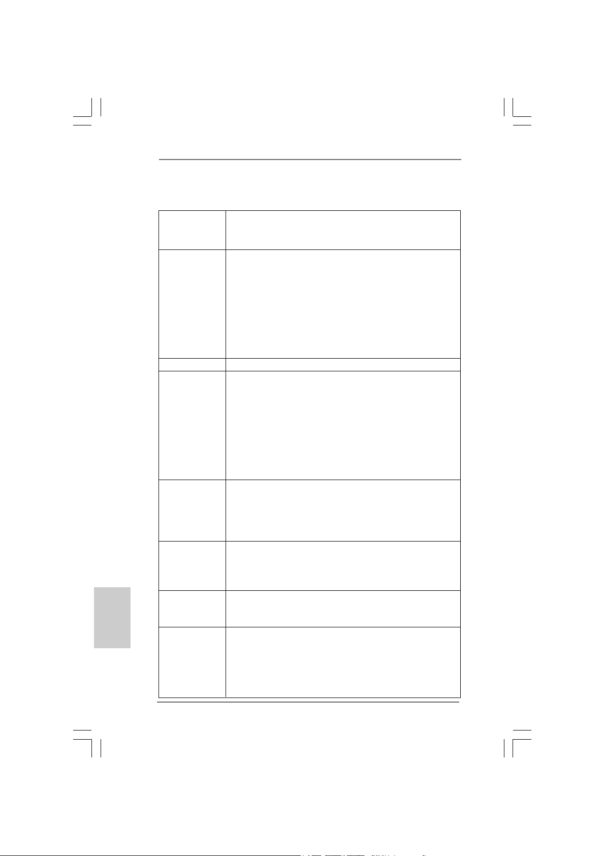
1.21.2
SpezifikationenSpezifikationen
1.2
Spezifikationen
1.21.2
SpezifikationenSpezifikationen
Plattform - ATX-Formfaktor: 30.5 cm x 24.4 cm; 12.0 Zoll x 8.6 Zoll
- Alle Feste Konden satordesign (100% in Japan gefertigte,
erstklassige leitfähige Polymer-Kondensatoren)
CPU - Unterstützt Intel® CoreTM i7- und Intel® CoreTM i5-Prozessoren
im LGA1156-Package
- Erweitertes V8 + 2-Stromphasendesign
- Unterstützt Intel® Turbo Boost-Technologie
- Unterstützt Hyper-Threading-Technologie
(siehe VORSICHT 1)
- Unterstützt Untied-Übertaktungstechnologie
(siehe VORSICHT 2)
- Unterstützt EM64T -CPU
Chipsatz - Intel® P55
Speicher - Unterstützung von Dual-Kanal-Speichertechnologie
(siehe VORSICHT 3)
- 4 x Steckplätze für DDR3
- Unterstützt DDR3 2600+(OC)/2133(OC)/1866(OC)/1600/
1333/1066 non-ECC, ungepufferter Speicher
- Max. Kapazität des Systemspeichers: 16GB
(siehe VORSICHT 4)
- Unterstützt Intel® Extreme Memory Profile (XMP)
(siehe VORSICHT 5)
Erweiterungs- - 1 x PCI Express 2.0 x16-Steckplatz (im x16-Modus)
steckplätze - 1 x PCI Express 2.0 x16-Steckplatz (im x4-Modus, 2,5 GT/s)
- 2 x PCI Express 2.0 x1-Steckplätze (2,5 GT/s)
- 2 x PCI -Steckplätze
- Unterstützt ATITM CrossFireXTM und Quad CrossFireX
Audio - 7.1 CH Windows® VistaTM Premium Niveau HD Audio mit dem
Inhalt Schutz
- DAC mit 110dB Aussteuerungsbere ich (ALC890 Audio Codec)
- Premium Blu-ray-Audio-Unterstützung
LAN - PCIE x1 Gigabit LAN 10/100/1000 Mb/s
- Realtek RTL81 1 1DL
- Unterstützt Wake-On-LAN
E/A-Anschlüsse I/O Panel
an der - 1 x PS/2-Mausanschluss
Rückseite - 1 x PS/2-Tastaturanschluss
- 1 x Koaxial-SPDIF-Ausgang
- 1 x optischer SPDIF-Ausgang
- 6 x Standard-USB 2.0-Anschlüsse
ASRock P55 Pro Motherboard
TM
Page 35
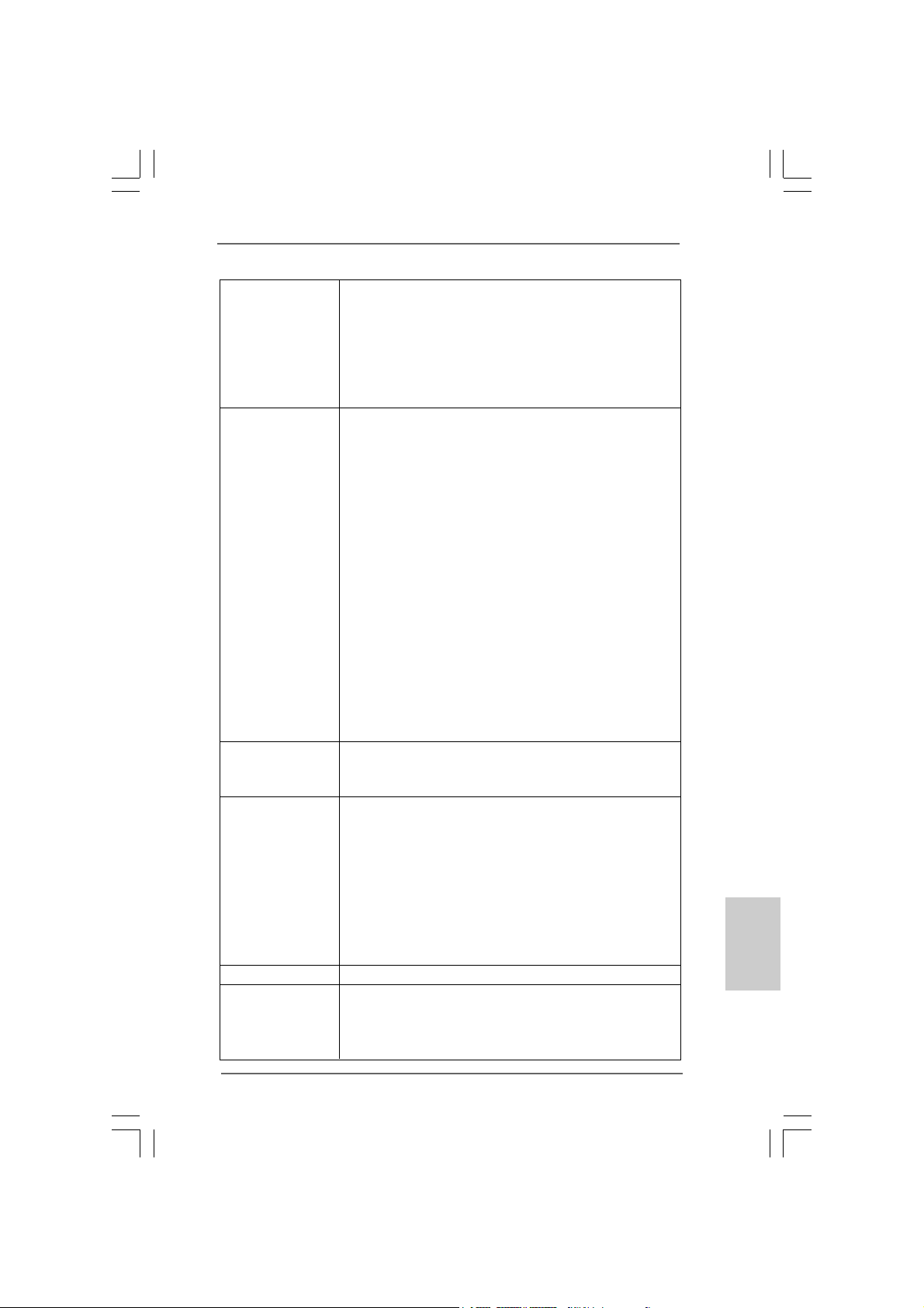
- 2 x eSATAII/USB-Anschluss mit Stromversorgung
- 1 x RJ-45 LAN Port mit LED (ACT/LINK LED und SPEED LED)
- 1 x IEEE 1394 Port
- 1 x CMOS löschen-Schalter mit LED
- HD Audiobuchse: Lautsprecher seitlich / Lautsprecher hinten
/ Mitte/Bass / Audioeingang/ Lautsprecher vorne / Mikrofon
(siehe VORSICHT 6)
Anschlüsse - 6 x Serial ATAII 3,0 GB/s-Anschlüsse, unterstützen RAID-
(RAID 0, RAID 1, RAID 10, RAID 5 und Intel Matrix Storage),
NCQ, AHCI und “Hot Plug” Funktionen (siehe VORSICHT 7)
- 1 x ATA133 IDE-Anschlüsse (Unterstützt bis 2 IDE-Geräte)
- 1 x F DD-Anschlüsse
- 1 x Infrarot-Modul-Header
- 1 x COM-Anschluss-Header
- 1 x HDMI_SPDIF-Anschluss
- 1 x IEEE 1394-Anschluss
- 1 x TPM-Stiftleiste
- CPU/Gehäuse/Stromlüfter-Anschluss
- 24-pin ATX-Netz-Header
- 8-pin anschluss für 12V -A TX-Netzte il
- Interne Audio-Anschlüsse
- Anschluss für Audio auf der Gehäusevorderseite
- 3 x USB 2.0-Anschlüsse (Unterstützung 6
zusätzlicher USB 2.0-Anschlüsse) (siehe VORSICHT 8)
- 1 x Dr. Debug (Debug-LED mit 7 Segmenten)
Schnellschalter - 1 x CMOS löschen-Schalter mit LED
- 1 x Netzschalter mit LED
- 1 x Rücksetzschalter (Reset) mit LED
BIOS - 16Mb AMI BIOS
- AMI legal BIOS mit Unterstützung für “Plug and Play”
- ACPI 1.1-Weckfunktionen
- JumperFree-Übertaktungstechnologie
- SMBIOS 2.3.1
- Zentraleinheit, VCCM, SB, VTT, VCCM REF, PCH_PLL
Stromspannung Multianpassung
- Unterstützt I. O. T. (Intelligente Übertakten Technologie)
- Unterstützt Smart BIOS
Support-CD - Treiber, Dienstprogramme, Antivirussoftwar (Probeversion)
Einzigartige - ASRock OC Tuner (siehe VORSICHT 9)
Eigenschaft - Intelligent Energy Saver (Intelligente Energiesparfunktion)
(siehe VORSICHT 10)
- Sofortstart
ASRock P55 Pro Motherboard
3535
35
3535
DeutschDeutsch
DeutschDeutsch
Deutsch
Page 36
- ASRock Instant Flash (siehe VORSICHT 11)
- Hybrid Booster:
- Schrittloser CPU-Frequenz-Kontrolle
(siehe VORSICHT 12)
- ASRock U-COP (siehe VORSICHT 13)
- Boot Failure Guard (B.F.G. – Systemstartfehlerschutz)
- Combo-Kühleroption (siehe VORSICHT 14)
- Gute Nacht-LED
Hardware Monitor - Überwachung der CPU-Temperatur
- Motherboardtemperaturerkennung
- Drehzahlmessung für CPU/Gehäuse/Stromlüfter
- CPU-Lüftergeräuschdämpfung
- Mehrstufige Geschwindigkeitsteuerung für CPU-/
Gehäuselüfter
- Spannungsüberwachung: +12V, +5V, +3.3V, Vcore
Betriebssysteme - Unterstützt Microsoft® Windows® XP / XP 64-Bit / VistaTM /
TM
Vista
64-Bit / Win7
Zertifizierungen - FCC, CE, WHQL
- Gemäß Ökodesign-Richtlinie (EuP) (Stromversorgung
gemäß Ökodesign-Richtlinie (EuP) erforderlich)
(siehe VORSICHT 15)
* Für die ausführliche Produktinformation, besuchen Sie bitte unsere Website:
http://www.asrock.com
WARNUNG
Beachten Sie bitte, dass Overclocking, einschließlich der Einstellung im BIOS, Anwenden
der Untied Overclocking-Technologie oder Verwenden von Overclocking-Werkzeugen von
Dritten, mit einem gewissen Risiko behaftet ist. Overclocking kann sich nachteilig auf die
Stabilität Ihres Systems auswirken oder sogar Komponenten und Geräte Ihres Systems
beschädigen. Es geschieht dann auf eigene Gefahr und auf Ihre Kosten. Wir übernehmen
keine Verantwortung für mögliche Schäden, die aufgrund von Overclocking verursacht
wurden.
Deutsch
DeutschDeutsch
DeutschDeutsch
3636
36
3636
VORSICHT!
1. Die Einstellung der “Hyper-Threading Technology”, finden Sie auf
Seite 55 des auf der Support-CD enthaltenen Benutzerhandbuches
beschrieben.
2. Dieses Motherboard unterstützt die Untied-Übertaktungstechnologie.
Unter “Entkoppelte Übertaktungstechnologie” auf Seite 31 finden Sie
detaillierte Informationen.
3. Dieses Motherboard unterstützt Dual-Kanal-Speichertechnologie. Vor
Implementierung der Dual-Kanal-Speichertechnologie müssen Sie die
Installationsanleitung für die Speichermodule auf Seite 43 zwecks richtiger
Installation gelesen haben.
ASRock P55 Pro Motherboard
Page 37
4. Durch Betriebssystem-Einschränkungen kann die tatsächliche
Speichergröße weniger als 4 GB betragen, da unter Windows® XP und
Windows® Vista™ etwas Speicher zur Nutzung durch das System
reserviert wird. Unter Windows® XP 64-bit und Windows® Vista™ 64-bit mit
64-Bit-CPU besteht diese Einschränkung nicht.
5. Für CPUs, die nur bis DDR3 1333 unterstützen, wird der XMP DDR3 1600
mittels Übertaktung unterstützt.
6. Der Mikrofoneingang dieses Motherboards unterstützt Stereo- und MonoModi. Der Audioausgang dieses Motherboards unterstützt 2-Kanal-, 4Kanal-, 6-Kanal- und 8-Kanal-Modi. Stellen Sie die richtige Verbindung
anhand der Tabelle auf Seite 3 her.
7. Vor Installation der SATAII-Festplatte an den SATAII-Anschluss lesen Sie
bitte “Setup-Anleitung für SATAII-Festplatte” auf Seite 36 der
“Bedienungsanleitung” auf der Support-CD, um Ihre SATAII-Festplatte
dem SATAII-Modus anzugleichen. Sie können die SATA-Festplatte auch
direkt mit dem SATAII-Anschluss verbinden.
8. Das Power Management für USB 2.0 arbeitet unter Microsoft® Windows
VistaTM 64-Bit / VistaTM / XP 64-Bit / XP SP1 oder SP2 einwandfrei.
9. Es ist ein benutzerfreundlicher ASRock Übertaktenswerkzeug, das
erlaubt, dass Sie Ihr System durch den Hardware-Monitor Funktion zu
überblicken und Ihre Hardware-Geräte übertakten, um die beste
Systemleistung unter der Windows® Umgebung zu erreichen.
Besuchen Sie bitte unsere Website für die Operationsverfahren von
ASRock OC Tuner.
ASRock-Website: http://www.asrock.com/feature/OCTuner/index.htm
10. Mit einem fortschrittlichen, eigenständigen Hard- und Softwaredesign
nutzt der Intelligent Energy Saver eine revolutionäre Technologie, die
bisher unerreichte Energieeinsparungen ermöglicht. Mit anderen
Worten: Sie verbrauchen besonders wenig Energie und erreichen
einen hohen Wirkungsgrad, ohne dass dies zu Lasten der
Rechenleistung geht. Auf unseren Internetseiten finden Sie einige
Erläuterungen zur Funktionsweise des Intelligent Energy Saver.
ASRock-Website: http://www.asrock.com/feature/IES/index.html
11. ASRock Instant Flash ist ein im Flash-ROM eingebettetes BIOS-FlashProgramm. Mithilfe dieses praktischen BIOS-Aktualisierungswerkzeugs
können Sie das System-BIOS aktualisieren, ohne dafür zuerst
Betriebssysteme wie MS-DOS oder Windows® aufrufen zu müssen. Mit
diesem Programm bekommen Sie durch Drücken der <F6>-Taste
während des POST-Vorgangs oder durch Drücken der <F2>-Taste im
BIOS-Setup-Menü Zugang zu ASRock Instant Flash. Sie brauchen dieses
Werkzeug einfach nur zu starten und die neue BIOS-Datei auf Ihrem
USB-Flash-Laufwerk, Diskettenlaufwerk oder der Festplatte zu
speichern, und schon können Sie Ihr BIOS mit nur wenigen
Klickvorgängen ohne Bereitstellung einer zusätzlichen Diskette oder
eines anderen komplizierten Flash-Programms aktualisieren. Achten Sie
darauf, dass das USB-Flash-Laufwerk oder die Festplatte das
Dateisystem FAT32/16/12 benutzen muss.
®
DeutschDeutsch
DeutschDeutsch
Deutsch
ASRock P55 Pro Motherboard
3737
37
3737
Page 38

12. Obwohl dieses Motherboard stufenlose Steuerung bietet, wird Over-
clocking nicht empfohlen. Frequenzen, die über den für den jeweiligen
Prozessor vorgesehenen liegen, können das System instabil werden
lassen oder die CPU beschädigen.
13. Wird eine Überhitzung der CPU registriert, führt das System einen
automatischen Shutdown durch. Bevor Sie das System neu starten,
prüfen Sie bitte, ob der CPU-Lüfter am Motherboard richtig funktioniert,
und stecken Sie bitte den Stromkabelstecker aus und dann wieder ein. Um
die Wärmeableitung zu verbessern, bitte nicht vergessen, etwas
Wärmeleitpaste zwischen CPU und Kühl körper zu sprühen.
14. Die Combo-Kühleroption bietet die flexible Möglichkeit zur Aufnahme von
zwei verschiedenen CPU-Kühlertypen, Socket LGA 775 und LGA 1156.
Beachten Sie bitte, dass nicht alle 775 CPU-Lüfter verwendet werden
können.
15. EuP steht für Energy Using Product und kennzeichnet die Ökodesign-
Richtlinie, die von der Europäischen Gemeinschaft zur Festlegung des
Energieverbrauchs von vollständigen Systemen in Kraft gesetzt wurde.
Gemäß dieser Ökodesign-Richtlinie (EuP) muss der gesamte
Netzstromverbrauch von vollständigen Systemen unter 1,00 Watt liegen,
wenn sie ausgeschaltet sind. Um dem EuP-Standard zu entsprechen, sind
ein EuP-fähiges Motherboard und eine EuP-fähige Stromversorgung
erforderlich. Gemäß einer Empfehlung von Intel muss eine EuP-fähige
Stromversorgung dem Standard entsprechen, was bedeutet, dass bei einem
Stromverbrauch von 100 mA die 5-Volt-Standby-Energieeffizienz höher als
50% sein sollte. Für die Wahl einer EuP-fähigen Stromversorgung
empfehlen wir Ihnen, weitere Details beim Hersteller der Stromversorgung
abzufragen.
Deutsch
DeutschDeutsch
DeutschDeutsch
3838
38
3838
ASRock P55 Pro Motherboard
Page 39
2. Installation2. Installation
2. Installation
2. Installation2. Installation
Sicherheitshinweise vor der MontageSicherheitshinweise vor der Montage
Sicherheitshinweise vor der Montage
Sicherheitshinweise vor der MontageSicherheitshinweise vor der Montage
Bitte nehmen Sie die folgende Sicherheitshinweise zur Kenntnis, bevor Sie das
Motherboard einbauen oder Veränderungen an den Einstellungen vornehmen.
1. Trennen Sie das System vom Stromnetz, bevor Sie eine ystemkomponente
berühren, da es sonst zu schweren Schäden a m Motherboard oder den
sonstigen internen, bzw. externen omponenten kommen kann.
2. Um Schäden aufgrund von statischer Elektrizität zu vermeiden, das
Motherboard NIEMALS auf einen Teppich o.ä.legen. Denken Sie außerem
daran, immer ein geerdetes Armband zu tragen oder ein geerdetes Objekt
aus Metall zu berühren, bevor Sie mit Systemkomponenten hantieren.
3. Halten Sie Komponenten immer an den Rändern und vermeiden Sie
Berührungen mit den ICs.
4. Wenn Sie Komponenten ausbauen, legen Sie sie immer auf eine
antistatische Unterlage, oder zurück in die Tüte, mit der die Komponente
geliefert wurde.
5. Wenn Sie das Motherboard mit den Schrauben an dem Computergehäuse
befestigen, überziehen Sie bitte die Schrauben nicht! Das Motherboard kann
sonst beschädigt werden.
2.1 CPU Installation2.1 CPU Installation
2.1 CPU Installation
2.1 CPU Installation2.1 CPU Installation
Für die Installation des Intel 1 156-Pin CPU
führen Sie bitte die folgenden Schritte durch.
(Ladeplatte)
(Kontaktreihe)
1156-Pin Sockel Übersicht
Bevor Sie die 1156-Pin CPU in den Sockel sitzen, prüfen Sie bitte,
ob die CPU-Oberfläche sauber ist und keine der Kontakte verbogen
sind. Setzen Sie die CPU nicht mit Gewalt in den Sockel, dies kann
die CPU schwer beschädigen.
ASRock P55 Pro Motherboard
(Sockel)
3939
39
3939
DeutschDeutsch
DeutschDeutsch
Deutsch
Page 40
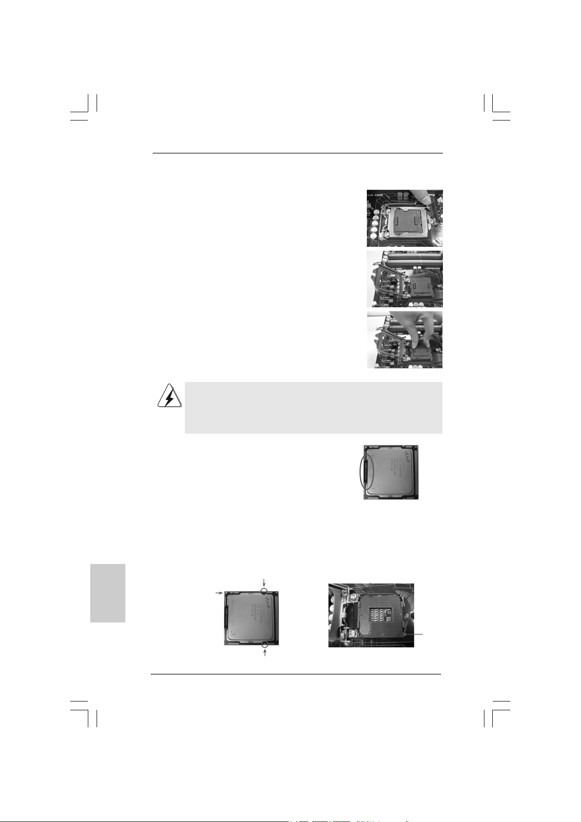
Schritt 1. Öffnen Sie den Sockel:
Schritt 1-1. Öffnen Sie den Hebel, indem
Sie ihn nach unten drücken und
aushaken.
Schritt 1-2. Drehen Sie den Ladehebel, bis
er in geöffneter Position steht,
ca. 135 Grad.
Schritt 1-3. Drehen Sie die Ladeplatte, bis
sie in geöffneter Position steht,
ca. 100 Grad.
Schritt 2. PnP-Kappe entfernen (Pick and Pla ce-Ka ppe).
1. Verwenden Sie beim Entfernen die Kappenlasche und
vermeiden Sie ein Abreißen der PnP-Kappe.
2. Diese Kappe muss angebracht werden, falls Sie das
Motherboard zur Reparatur bringen.
Schritt 3. 1156-Pin CPU einstecken:
Schritt 3-1. Halten Sie die CPU an den mit
schwarzen Linien
gekennzeichneten Seiten.
Linie
Schwarze
Deutsch
DeutschDeutsch
DeutschDeutsch
4040
40
4040
Schritt 3-2. Halten Sie das Teil mit dem IHS
(Integrated Heat Sink –
integrierter Kühlkörper) nach
oben. Suchen Sie Pin 1 und die
zwei Orientierungseinkerbungen.
Orientierungskerbe
Pin1
Orientierungskerbe
1156-Pin CPU
ASRock P55 Pro Motherboard
Ausrichtungsmarkierung
Pin1
Ausrichtungsmarkierung
1156-Pin Sockel
Page 41
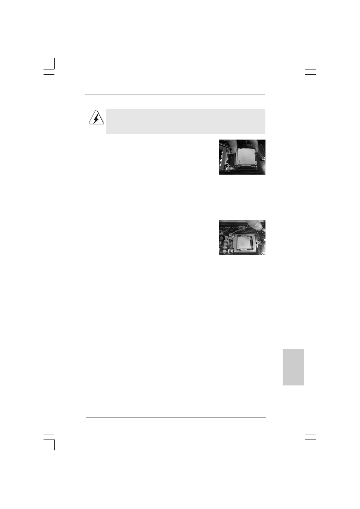
Um die CPU ordnungsgemäß einsetzen zu können, richten Sie
die zwei Orientierungskerben der CPU mit den beiden
Markierungen des Sockels aus.
Schritt 3-3. Drücken Sie die CPU vorsichtig
in vertikaler Richtung in den
Sockel.
Schritt 3-4. Prüfen Sie, dass die CPU
ordnungsgemäß im Sockel sitzt
und die Orientierungskerben
einwandfrei in den
entsprechenden Auskerbungen
sitzen.
Schritt 4. Sockel schließen:
Schritt 4-1. Drehen Sie die Ladeplatte auf
den Kühlkörper (IHS).
Schritt 4-2. Drücken Sie leicht auf die
Ladeplatte und schließen Sie
den Ladehebel.
Schritt 4-3. Sichern Sie Ladehebel und
Ladeplatte mithilfe des
Hebelverschlusses.
ASRock P55 Pro Motherboard
4141
41
4141
DeutschDeutsch
DeutschDeutsch
Deutsch
Page 42
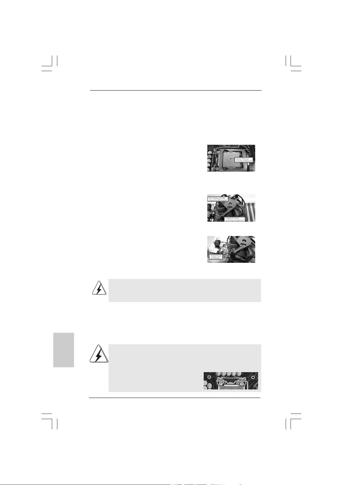
2.22.2
Installation des CPU-Lüfters und KühlkörpersInstallation des CPU-Lüfters und Kühlkörpers
2.2
Installation des CPU-Lüfters und Kühlkörpers
2.22.2
Installation des CPU-Lüfters und KühlkörpersInstallation des CPU-Lüfters und Kühlkörpers
Für Installationshinweise, siehe Betriebsanleitung Ihres CPU-Lüfters und
Kühlkörpers.
Unten stehend ein Beispiel zur Installation eines Kühlkörpers für den 1156-Pin CPU.
Schritt 1. Geben Sie Wärmeleitmaterial auf die Mitte
des IHS, auf die Sockeloberfläche.
Schritt 2. Setzen Sie den Kühlkörper auf den Sockel.
Prüfen Sie, dass die Lüfterkabel auf der
Seite am nächsten zum CPU-LüfterAnschluss des Motherboards verlaufen
(CPU_FAN1, siehe Seite 2, Nr. 37).
Schritt 3. Richten Sie Verbindungselemente und
Löcher im Motherboard aus.
Schritt 4. Drehen Sie die Verbindungselemente im
Uhrzeigersinn und drücken Sie mit dem
Daumen auf die Kappen der Elemente zum
Feststellen. Wiederholen Sie dies mit den
anderen Verbindungselementen.
Wenn Sie die Verbindungselemente nur drücken, ohne sie im
Uhrzeigersinn zu drehen, wird der Kühlkörper nicht ordnungsgemäß
am Motherboard befestigt.
(Tragen Sie Wärmeleitmaterial auf. )
(Lüfterkabel auf der Seite am nächsten
zum Anschluss des Motherboards)
(Schlitze der Verbindungselemente
nach außen)
(Nach unten drücken (4 Stellen))
Deutsch
DeutschDeutsch
DeutschDeutsch
4242
42
4242
Schritt 5. Schließen Sie den Lüfter an den CPU-
Lüfteranschluss des Motherboards.
Schritt 6. Befestigen Sie überschüssiges Kabel mit
Band, um eine Störung des Lüfters oder
Kontakt mit anderen Teilen zu vermeiden.
Beachten Sie bitte, dass dieses Motherboard die ComboKühleroption unterstützt, die eine flexible Möglichkeit zur Aufnahme
von zwei verschiedenen CPU-Kühlertypen, Socket LGA 775 und
LGA 1156, bietet. Das weiße Durchgangsloch ist für den CPULüfter im Socket LGA 1156 vorgesehen.
ASRock P55 Pro Motherboard
Page 43
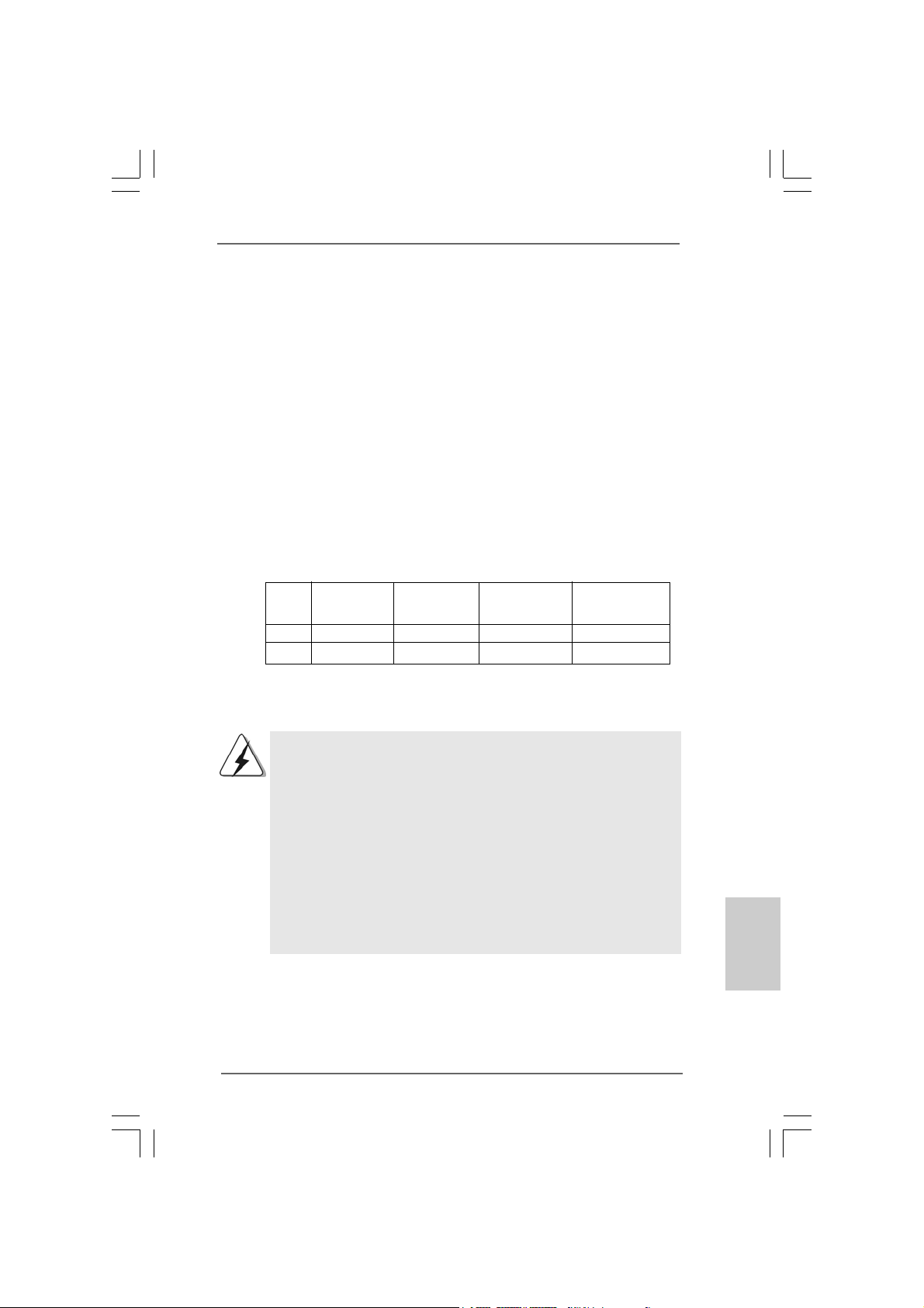
2.3 Installation der Speichermodule (DIMM)2.3 Installation der Speichermodule (DIMM)
2.3 Installation der Speichermodule (DIMM)
2.3 Installation der Speichermodule (DIMM)2.3 Installation der Speichermodule (DIMM)
Die Motherboards P55 Pro bieten vier 240-pol. DDR3 (Double Data Rate 3) DIMM-
Steckplätze und unterstützen die Dual-Kanal-Speichertechnologie. Für die DualKanalkonfiguration dürfen Sie nur identische (gleiche Marke, Geschwindigkeit,
Größe und gleicher Chiptyp) DDR3 DIMM-Paare in den Steckplätzen gleicher Farbe
installieren. Mit anderen Worten, sie müssen ein identisches DDR3 DIMM-Paar im
Dual-Kanal (DDR3_A1 und DDR3_B1; Weiß Steckplätze, siehe Seite 2 Nr. 5)
installieren, damit die Dual-Kanal-Speichertechnologie aktiviert werden kann. Auf
diesem Motherboard können Sie auch vier DDR3 DIMMs für eine DualKanalkonfiguration installieren. Auf diesem Motherboard können Sie auch vier
DDR3 DIMM-Module für eine Dual-Kanalkonf iguration in stallieren, wobei Sie bitte in
allen vier Steckplätzen identische DDR3 DIMM-Module installieren. Beziehen Sie
sich dabei auf die nachstehende Konfigurationstabelle für Dual-Kanalspeicher.
Dual-Kanal-Speicherkonfigurationen
DDR3_A2 DDR3_A1 DDR3_B2 DDR3_B1
(Blau) (Weiß) (Blau) (Weiß)
(1) - Bestückt - Bestückt
(2)* Bestückt Bestückt Bestückt Bestückt
* Für Konfiguration (2) installieren Sie bitte identische DDR3 DIMMs in allen vier
Steckplätzen.
1. Wenn Sie zwei Spe ichermodule in stallieren möchten, verwenden Sie
dazu für optimale Kompatibilität und Stabilität Steckplätze gleicher
Farbe. Installieren Sie die beiden Speichermodule also entweder in
den Weiß Steckplätzen (DDR3_A1 und DDR3_B1).
2. Wenn nur ein Speichermodul oder drei Speichermodule in den DDR3
DIMM-Steckplätzen auf diesem Motherboard installiert sind, kann es
die Dual-Kanal-Speichertechnologie nicht aktivieren.
3. Es ist nicht zulässig, DDR oder DDR2 in einen DDR3 Steckplatz zu
installieren; andernfalls könnten Motherboard und DIMMs beschädigt
werden.
4. Installieren Sie das Speichermodul für die erste Priorität im weißen
Steckplatz (DDR3_B1).
ASRock P55 Pro Motherboard
4343
43
4343
DeutschDeutsch
DeutschDeutsch
Deutsch
Page 44
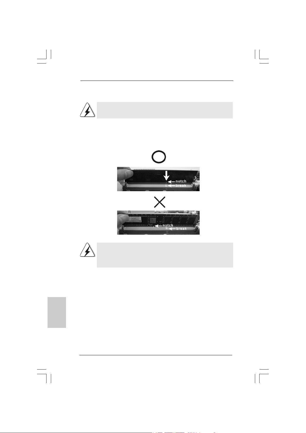
Einsetzen eines DIMM-ModulsEinsetzen eines DIMM-Moduls
Einsetzen eines DIMM-Moduls
Einsetzen eines DIMM-ModulsEinsetzen eines DIMM-Moduls
Achten Sie darauf, das Netzteil abzustecken, bevor Sie DIMMs oder
Systemkomponenten hinzufügen oder entfernen.
Schritt 1: Öffnen Sie einen DIMM-Slot, inde m Sie die seitlichen Cli ps n ach außen
drücken.
Schritt 2: Richten Sie das DIMM-Modul so über dem Slot aus, dass das Modul mit
der Kerbe in den Slot passt.
Deutsch
DeutschDeutsch
DeutschDeutsch
4444
44
4444
Die DIMM-Module passen nur richtig herum eingelegt in die
Steckplätze. Falls Sie versuchen, die DIMM-Module mit Gewalt
falsch herum in die Steckplätze zu zwingen, führt dies zu
dauerhaften Schäden am Mainboard und am DIMM-Modul.
Schritt 3: Drücken Sie die DIMM-Module fest in die Steck plätze, so dass die
Halteklammern a n beiden Enden de s Moduls einschn a ppen und das
DIMM-Modul fest an Ort und Stelle sitzt.
ASRock P55 Pro Motherboard
Page 45
2.42.4
Erweiterungssteckplätze (PCI-Steckplätze und PCIErweiterungssteckplätze (PCI-Steckplätze und PCI
2.4
Erweiterungssteckplätze (PCI-Steckplätze und PCI
2.42.4
Erweiterungssteckplätze (PCI-Steckplätze und PCIErweiterungssteckplätze (PCI-Steckplätze und PCI
ExpressExpress
Express
ExpressExpress
Es gibt einen 2 PCI-Steckplätze und 4 PCI Express-Steckplätze am P55 Pro
Motherboard.
PCI-Slots: PCI-Slots werden zur Installation von Erweiterungskarten mit
PCI Express-Slots:
-Steckplätze)-Steckplätze)
-Steckplätze)
-Steckplätze)-Steckplätze)
dem 32bit PCI-Interface genutzt.
PCIE1 / PCIE3 (PCIE x1-Steckplatz; weiß) wird für PCI
Express-Karten mit x1 Lane-Breite-Karten verwendet, z.B.
Gigabit LAN-Karte, SATA2-Karte.
PCIE2 (PCIE x16-Steckplatz; blau) wird für PCI Express
x16 Lane-Breite-Grafikkarten oder für die Installation von PCI
Express-Grafikkarten verwendet, um die CrossFireXTMFunktion zu unterstützen.
PCIE4 (PCIE x16-Steckplatz; orange) wird für PCI Express x1
Lane-Breite-Karten verwendet, z.B. Gigabit LAN-Karte,
SATA2-Karte, etc., oder für die Installation von PCI ExpressGrafikkarten, um die CrossFireXTM-Funktion zu unterstützen.
1. Im Einzel-VGA-Kartenmodus wird empfohlen, eine PCI Express
x16-Grafikkarte im PCIE2-Steckplatz zu installieren.
2. Im CrossFireXTM-Modus installieren Sie PCI Express x16Grafikkarten in den PCIE2- und PCIE4-Steckplätzen. Daher
funktioniert der PCIE2-Steckplätze mit x16-Bandbreite, die
PCIE4-Steckplatz aber mit x4-Bandbreite.
3. Verbinden Sie einen Gehäuselüfter mit dem MotherboardGehäuselüfteranschluss (CHA_FAN1 oder CHA_FAN2), wenn
Sie mehrere Grafikkarten für eine bessere Wärmeumgebung
verwenden.
Einbau einer ErweiterungskarteEinbau einer Erweiterungskarte
Einbau einer Erweiterungskarte
Einbau einer ErweiterungskarteEinbau einer Erweiterungskarte
Schritt 1: Bevor Sie die Erweiterungskarte installieren, vergewissern Sie sich,
dass das Netzteil ausge schaltet und das Netzka bel a bgezogen ist.
Bitte lesen Sie die Dokumentation zur Erweiterungsk arte und nehmen
Sie nötige Hardware-Einstellungen für die Karte vor, ehe Sie mit der
Installation beginnen.
Schritt 2: Entfernen Sie das Abdeckungsble ch (Slotblende) von dem
Gehäuseschacht (Slot) , den Sie nutzen möchten und behalten die
Schraube für den Einbau der Karte.
Schritt 3: Richten Sie die Karte über dem Slot aus und drücken Sie sie ohne
Gewalt hinein, bis sie den Steckplatz korrekt ausfüllt.
Schritt 4: Befestigen Sie die Karte mit der Schraube aus Schritt 2.
ASRock P55 Pro Motherboard
4545
45
4545
DeutschDeutsch
DeutschDeutsch
Deutsch
Page 46

TMTM
TM
2.52.5
CrossFireXCrossFireX
2.5
CrossFireX
2.52.5
CrossFireXCrossFireX
BedienungsanleitungBedienungsanleitung
Bedienungsanleitung
BedienungsanleitungBedienungsanleitung
Dieses Motherboard unterstützt die CrossFireXTM- und Quad CrossFireXTMFunktion. CrossFireXTM-Technologie bietet die am vorteilhaftesten zur Verfügung
stehende Methode zur Kombination mehrerer leistungsstarker Grafikprozessoren
(GPU) in einem einzelnen PC. Die Kombination einer Reihe unterschiedlicher
Betriebsmodi mit intelligentem Softwaredesign und einem innovativen
Schaltmechanismus ermöglicht CrossFireXTM die optimalste Leistung und
Bildqualität in einer 3D-Anwendung. Derzeit wird die CrossFireXTM-Funktion von
den Betriebssystemen Windows® XP mit Service Pack 2 und VistaTM unterstützt.
Die Quad CrossFireXTM-Funktion wird nur vom Betriebssystem Windows® Vista
unterstützt. Schauen Sie auf der AMD-Website nach, ob es ATITM CrossFireXTMTreiber-Updates gibt. Beachten Sie den detailliert erklärten Installationsablauf auf
Seite 16.
2.6 “Surround Display”2.6 “Surround Display”
2.6 “Surround Display”
2.6 “Surround Display”2.6 “Surround Display”
Dieses Motherboard unterstützt Surround Display-Aufrüstung. Mit zusätzlichen
PCI Express-VGA-Karte können Sie die Vorteile der Surround Display-Funktion
problemlos genießen. Für detaillierte Informationen, siehe folgendes Dokument auf
beiliegender Support-CD: ..\ Surround Display Information
TMTM
- und Quad CrossFireX- und Quad CrossFireX
- und Quad CrossFireX
- und Quad CrossFireX- und Quad CrossFireX
TMTM
TM
TMTM
--
-
--
TM
Deutsch
DeutschDeutsch
DeutschDeutsch
4646
46
4646
ASRock P55 Pro Motherboard
Page 47
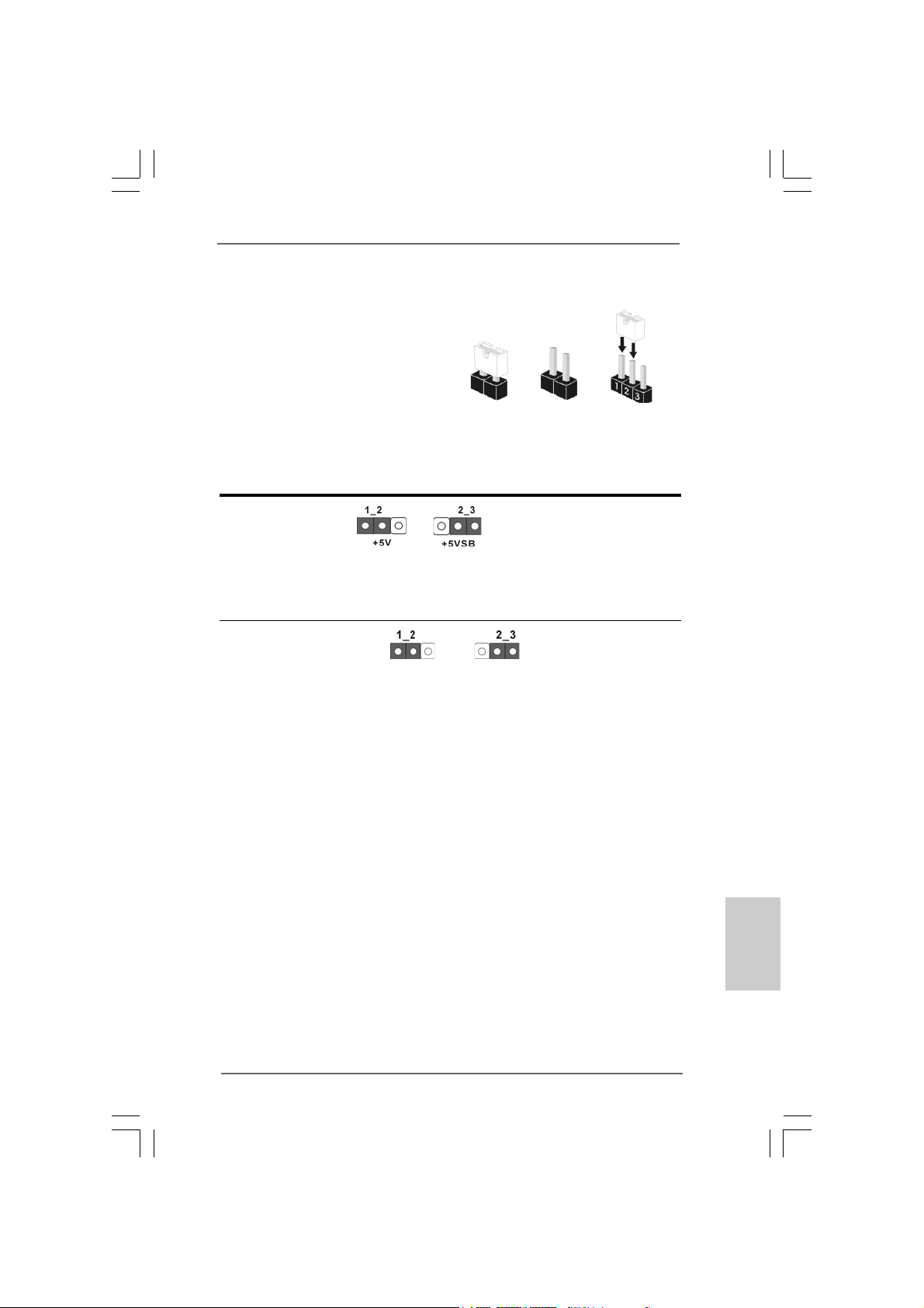
2.7 Einstellung der Jumper2.7 Einstellung der Jumper
2.7 Einstellung der Jumper
2.7 Einstellung der Jumper2.7 Einstellung der Jumper
Die Abbildung verdeutlicht, wie Jumper
gesetzt werden. Werden Pins durch
Jumperkappen verdeckt, ist der Jumper
“Gebrückt”. Werden keine Pins durch
Jumperkappen verdeckt, ist der Jumper
“Offen”. Die Abbildung zeigt einen 3-Pin
Jumper dessen Pin1 und Pin2 “Gebrückt”
sind, bzw. es befindet sich eine JumperKappe auf diesen beiden Pins.
Jumper Einstellun Beschreibung
PS2_USB_PWR1 Überbrücken Sie Pin2, Pin3, um
(siehe S.2 - No. 1) +5VSB (Standby) zu setzen
Hinweis: Um +5VSB nutzen zu können, muss das Netzteil auf dieser Leitung 2A
oder mehr leisten können.
CMOS löschen
(CLRCMOS1, 3-Pin jumper)
(siehe S.2 - Nr. 15)
Hinweis: CLRCMOS1 erlaubt Ihnen das Löschen der CMOS-Daten. Diese beinhalten
das System-Passwort, Datum, Zeit und die verschiedenen BIOS-Parameter.
Um die Systemparameter zu löschen und auf die Werkseinstellung
zurückzusetzen, schalten Sie bitte den Computer ab und entfernen da s
Stromkabel. Benutzen Sie eine Jumperkappe, um die Pin 2 und Pin 3 an
CLRCMOS1 für 5 Sekunden kurzzuschließen. Bitte vergessen Sie nicht,
den Jumper wieder zu entfernen, nachdem das CMOS gelöscht wurde. Bitte
vergessen Sie nicht, den Jumper wieder zu entfernen, nachde m da s CMOS
gelöscht wurde. W enn Sie den CMOS-Inhalt gleich n a ch de m Aktualisieren
des BIOS löschen müssen, müssen Sie zuerst da s System starten und
dann wieder ausschalten, bevor Sie den CMOS-Inhalt löschen.
DefaultEinstellung
Gebrückt Offen
und die PS/2 oder USBWe ckfunktionen zu aktivieren.
CMOS
löschen
ASRock P55 Pro Motherboard
4747
47
4747
DeutschDeutsch
DeutschDeutsch
Deutsch
Page 48
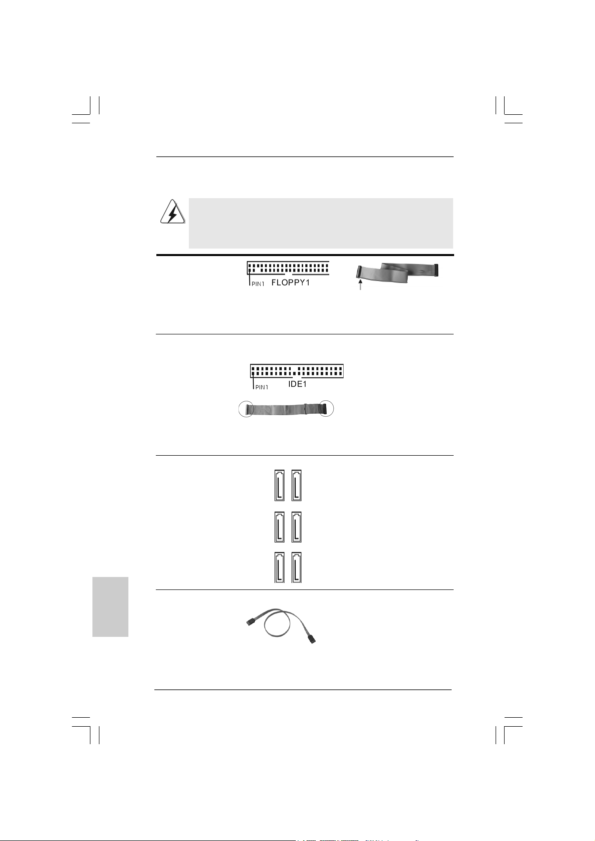
2.8 Integrierte Header und Anschlüsse2.8 Integrierte Header und Anschlüsse
2.8 Integrierte Header und Anschlüsse
2.8 Integrierte Header und Anschlüsse2.8 Integrierte Header und Anschlüsse
Integrierte Header und Anschlüsse sind KEINE Jumper. Setzen Sie KEINE
Jumperkappen auf diese He ader und Anschlüsse. Wenn Sie Jumperkappen
auf Header und Anschlüsse setzen, wird das Motherboard unreparierbar
beschädigt!
Anschluss für das
Floppy-Laufwerk
(33-Pin FLOPPY1)
(siehe S.2 - No. 27)
die rotgestreifte Seite auf Stift 1
Hinweis: Achten Sie darauf, dass die rotgestreifte Seite des Ka bel mit der Stift 1-
Seite des An schlusses verbunden wird.
Primärer IDE-Anschluss (blau)
(39-pin IDE1, siehe S.2 - No. 14)
Blauer Anschluss Schwarzer Anschluss
zum Motherboard zur Festplatte
80-adriges A T A 66/100/133 Kabel
Hinweis: Details entnehmen Sie bitte den Anweisungen Ihres IDE-Gerätehändlers.
Seriell-ATAII-Anschlüsse Diese sechs Serial ATAII-
(SATAII_1_2: (SAT AII-)V erbínder unterstützten
siehe S.2 - No. 9) SATA-Datenkabel für interne
(SATAII_3_4: Ma ssenspeichergeräte. Die
siehe S.2 - No. 10) aktuelle SATAII-Schnittstelle
(SATAII_5_6: ermöglicht eine
siehe S.2 - No. 1 1) Datenübertragungsrate bis
3,0 Gb/s.
Deutsch
DeutschDeutsch
DeutschDeutsch
4848
48
4848
SAT AII_5_6 SA T AII_3_4 SA T AII_1_2
Serial A TA- (SA TA-) SJedes Ende des SA T A
Datenkabel Datenkabels ka nn a n die SA TA
(Option) / SATAII Festplatte oder da s
SAT AII V erbindungsstück auf
dieser Hauptplatine
angeschlossen werden.
ASRock P55 Pro Motherboard
Page 49
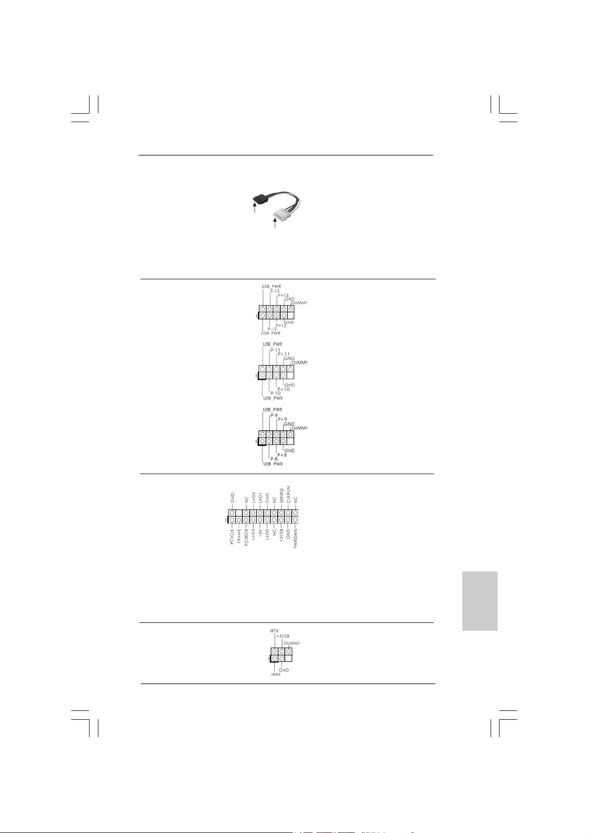
Serial A TA- (SATA-) Verbinden Sie das schwarze
Stromversorgungskabel Ende des SATA-Netzkabels mit
(Option) dem Netzan schluss am
SATA-HDD-Stromanschluss
Verbindung zum
Verbindung zum
Netzteil
Laufwerk. Verbinden Sie dann
das weiße Ende des SATAStromversorgungskabels mit
dem Stromanschluss des
Netzteils.
USB 2.0-Header Zusätzlich zu den sechs
(9-pol. USB12_13) üblichen USB 2.0-Ports an den
(siehe S.2 - No. 23) I/O-Anschlüssen befinden sich
drei USB 2.0Anschlussleisten am
Motherboard. Pro USB 2.0-
(9-pol. USB10_11) Anschlussleiste werden zwei
(siehe S.2 - No. 24) USB 2.0-Ports unterstützt.
(9-pol. USB8_9)
(siehe S.2 - No. 25)
TPM-Stiftleiste Dieser Anschluss unterstützt ein
(19-Pin TPM1) Trusted Platform Module-System
(siehe S.2 - No. 19) (TPM: Vertrauenswürdiges
Plattformmodul), auf dem sich
Schlüssel, Digitalzertifikate,
Kennwörter und Daten auf
sichere Weise speichern lassen.
Ein TPM-System hilft auch bei
der Verbesserung der
Netzwerksicherheit, schützt
digitale Identitäten und sorgt für
Plattformintegrität.
Infrarot-Modul-Header Dieser Header unterstützt ein
(5-pin IR1) optionales, drahtloses Sende-
(siehe S.2 - No. 21) und Empfangs-Infrarotmodul.
ASRock P55 Pro Motherboard
4949
49
4949
DeutschDeutsch
DeutschDeutsch
Deutsch
Page 50
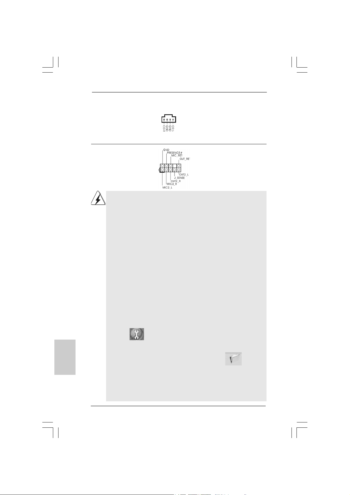
Interne Audio-Anschlüsse Diese ermöglichen Ihnen
(4-Pin CD1) Stereo-Signalquellen, wie z. B.
(siehe S.2 - No. 31) CD-ROM, DV D-ROM, TV-Tuner
CD1
oder MPEG-Karten mit Ihrem
System zu verbinden.
Anschluss für Audio auf Dieses Interface zu einem
der Gehäusevorderseite Audio-Panel auf der Vorderseite
(9-Pin HD_AUDIO1) Ihres Gehäuses, ermöglicht
(siehe S.2 - No. 30) Ihnen eine bequeme
Anschlussmöglichkeit und
Kontrolle über Audio-Geräte.
1. High Definition Audio unterstützt Jack Sensing (automatische Erkennung
falsch angeschlossener Geräte), wobei jedoch die Bildschirmverdrahtung
am Gehäuse HDA unterstützen muss, um richtig zu funktionieren.
Beachten Sie bei der Installation im System die Anweisungen in unserem
Handbuch und im Gehäusehandbuch.
2. Wenn Sie die AC’97-Audioleiste verwenden, installieren Sie diese wie
nachstehend beschrieben an der Front-Audioanschlussleiste:
A. Schließen Sie Mic_IN (MIC) an MIC2_L an.
B. Schließen Sie Audio_R (RIN) an OUT2_R und Audio_L (LIN) an
OUT2_L an.
C. Schließen Sie Ground (GND) an Ground (GND) an.
D. MIC_RET und OUT_RET sind nur für den HD-Audioanschluss
gedacht. Diese Anschlüsse müssen nicht an die AC’97-Audioleiste
angeschlossen werden.
E. Rufen Sie das BIOS-Setup-Dienstprogramm auf. Wechseln Sie zu
Erweiterte Einstellungen und wählen Sie Chipset-Konfiguration.
Setzen Sie die Option Frontleistenkontrolle von [Automatisch] auf
[Aktiviert].
F. Rufen Sie das Windows-System auf. Klicken Sie auf das Symbol in der
Taskleiste unten rechts, um den Realtek HD Audio-Manager aufzurufen.
Für Windows® XP / XP 64-Bit Betriebssystem:
Klicken Sie auf “Audio-E/A”, wählen Sie die “Anschlusseinstellungen”
, wählen Sie “Erkennung der Frontleistenbuchse
Deutsch
DeutschDeutsch
DeutschDeutsch
5050
50
5050
deaktivieren” und speichern Sie die Änderung durch Klicken auf “OK”.
Für Windows® Vista
Die Rechtoberseite „Dateiordner“ Ikone anklicken ,
„Schalttafel Buchse Entdeckung sperren“ wählen und die Änderung
speichern, indem Sie „OKAY“ klicken.
G. Aktivierung des vorderseitigen Mikrofons.
Für Betriebssystem Windows® XP / XP 64-Bit:
Wählen Sie “Front Mic” (Vorderes Mikr.) als Standard-Aufnahmegerät.
Möchten Sie Ihre Stimme über das vorderseitige Mikrofon hören, dann
TM
/ VistaTM 64-Bit Betriebssystem:
ASRock P55 Pro Motherboard
Page 51
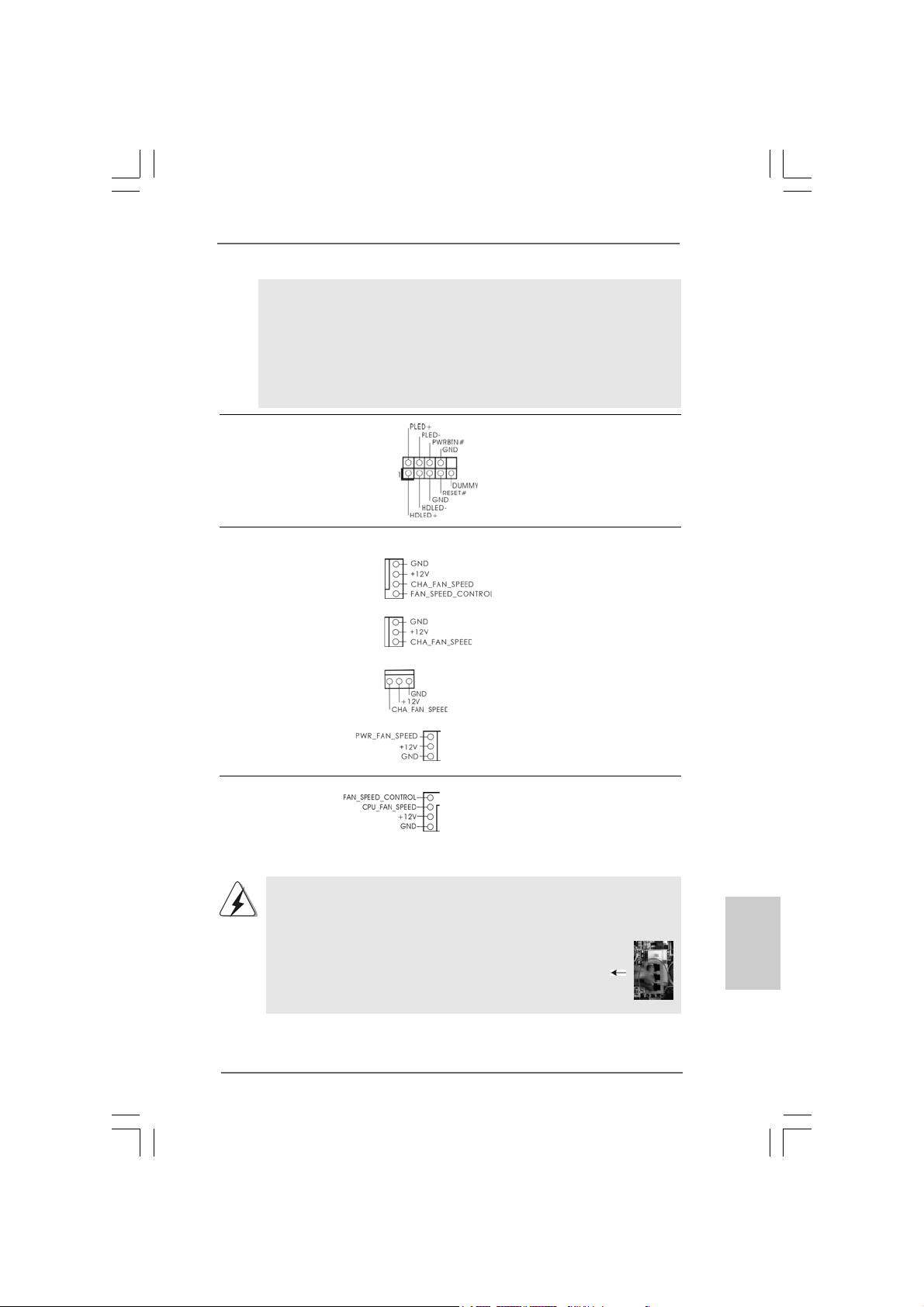
wählen Sie bitte das Symbol “Mute” (Stumm) unter “Front Mic”
(Vorderes Mikr.) im Abschnitt “Playback” (Wiedergabe) ab.
Für Betriebssystem Windows® Vista
Rufen Sie die Registerkarte “Front Mic” (Vorderes Mikr.) im Realtek Bedienfeld auf. Klicken Sie auf “Set Default Device” (Standardgerät
einstellen), um das vorderseitige Mikrofon als Standard Aufnahmegerät zu übernehmen.
TM
/ VistaTM 64-Bit:
System Panel-Header Dieser Header unterstützt
(9-pin PANEL1) mehrere Funktion der
(siehe S.2 - No. 22) Systemvorderseite.
Gehäuse- und Stromlüfteranschlüsse
(4-pin CHA_FAN1)
(siehe S.2 - No. 7)
Verbinden Sie die Lüfterkabel mit
den Lüfteranschlüssen, wobei
der schwarze Dra ht a n den
Schutzleiterstift angeschlossen
(3-pin CHA_FAN2)
(siehe S.2 - No. 8)
(3-pin CHA_FAN3)
(siehe S.2 - No. 12)
(3-pin PWR_FAN1)
(siehe S.2 - No. 38)
CPU-Lüfteranschluss Verbinden Sie da s CPU -
(4-pin CPU_FAN1) Lüfterkabel mit diesem
(siehe S.2 - No. 37) Anschluss und passen Sie den
4
3
2
1
wird.
schwarzen Draht dem
Erdungsstift an.
Obwohl dieses Motherboard einen vierpoligen CPU-Lüfteranschluss (Quiet
Fan) bietet, können auch CPU-Lüfter mit dreipoligem Anschluss
angeschlossen werden; auch ohne Geschwindigkeitsregulierung. Wenn Sie
einen dreipoligen CPU-Lüfter an den CPU-Lüferanschluss dieses
Motherboards anschließen möchten, verbinden Sie ihn bitte mit
den Pins 1 – 3.
Lüfter mit dreipoligem Anschluss installieren
Pins 1–3 anschließen
DeutschDeutsch
DeutschDeutsch
Deutsch
ASRock P55 Pro Motherboard
5151
51
5151
Page 52
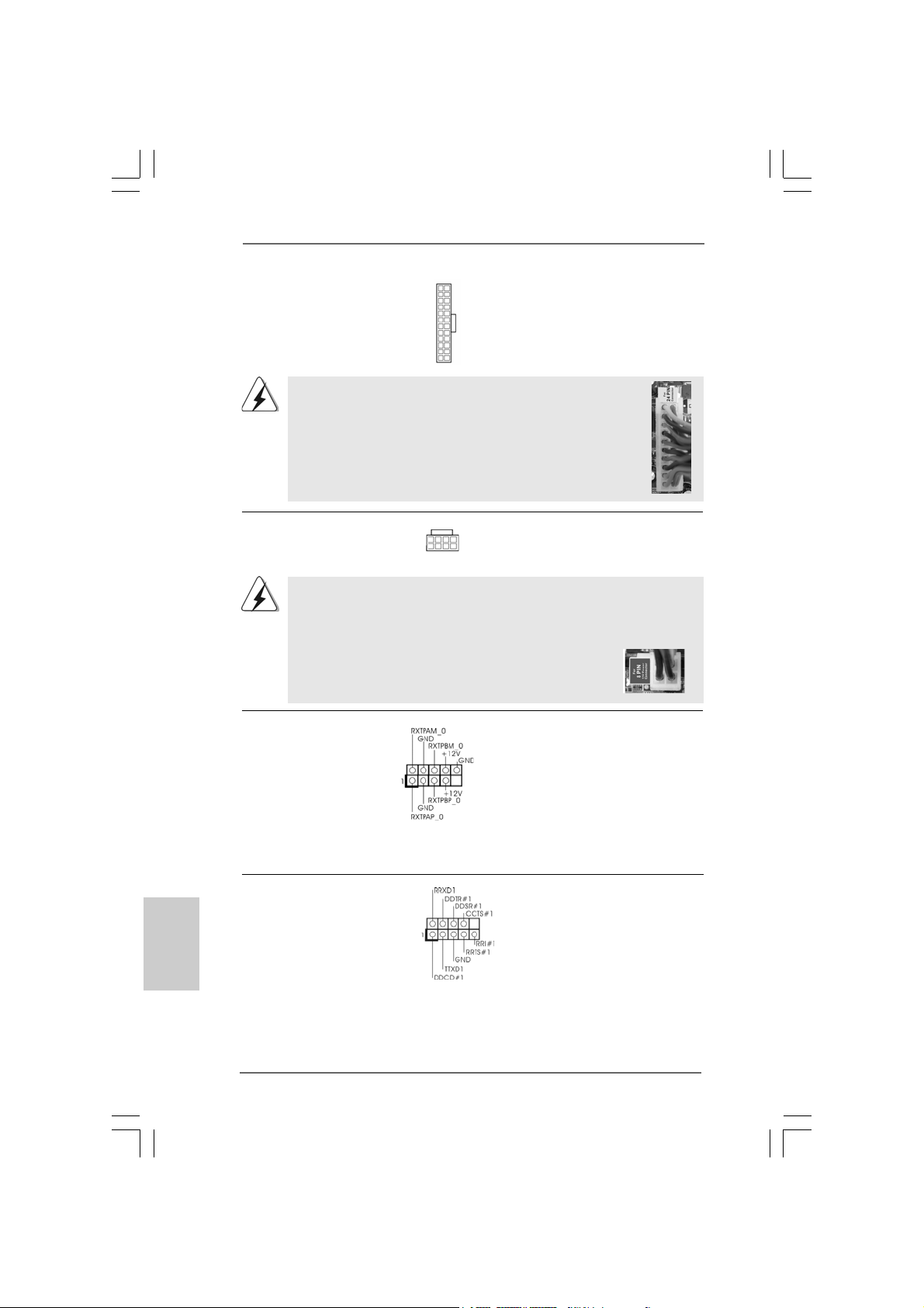
ATX-Netz-Header Verbinden Sie die ATX-
(24-pin ATXPWR1) Stromversorgung mit diesem
(siehe S.2 - No. 6) Header.
12 124
13
Obwohl dieses Motherboard einen 24-pol. ATX-Stromanschluss
12
bietet, kann es auch mit einem modifizierten traditionellen 20-pol.
ATX-Netzteil verwendet werden. Um ein 20-pol. ATX-Netzteil zu
verwenden, stecken Sie den Stecker mit Pin 1 und Pin 13 ein.
Installation eines 20-pol. A TX-Netzteils
ATX 12V Anschluss Bitte schließen Sie an diesen
(8-pin ATX12V1) Anschluss die A TX 12V
(siehe S.2 - No. 2) Stromversorgung an.
8 5
4 1
1
Obwohl diese Hauptplatine 8-Pin ATX 12V Stromanschluss zur Verfügung
stellt, kann sie noch arbeiten, wenn Sie einen traditionellen 4-Pin ATX 12V
Energieversorgung adoptieren. Um die 4-Pin ATX Energieversorgung zu
verwenden, stecken Sie bitte Ihre Energieversorgung
zusammen mit dem Pin 1 und Pin 5 ein.
Installation der 4-Pin A TX 12V Energieversorgung
8 5
4 1
IEEE-1394 Header Außer einem vorgegebenem
(9-pin FRONT_1394) IEEE-1394 Port auf dem Ein-/
(siehe S.2 - No. 26) Ausgabe Paneel, gibt es einen
IEEE-1394 Header
(FRONT_1394) auf dieser
Hauptplatine. Dieser IEEE-1394
Header ka nn einen IEEE-1394
Port unterstützen.
24
13
Deutsch
DeutschDeutsch
DeutschDeutsch
5252
52
5252
COM-Anschluss-Header Dieser COM-Anschluss-
(9-pin COM1) Header wird verwendet, um
(siehe S.2 - No. 28) ein COM-Anschlussmodul zu
unterstützen.
ASRock P55 Pro Motherboard
Page 53
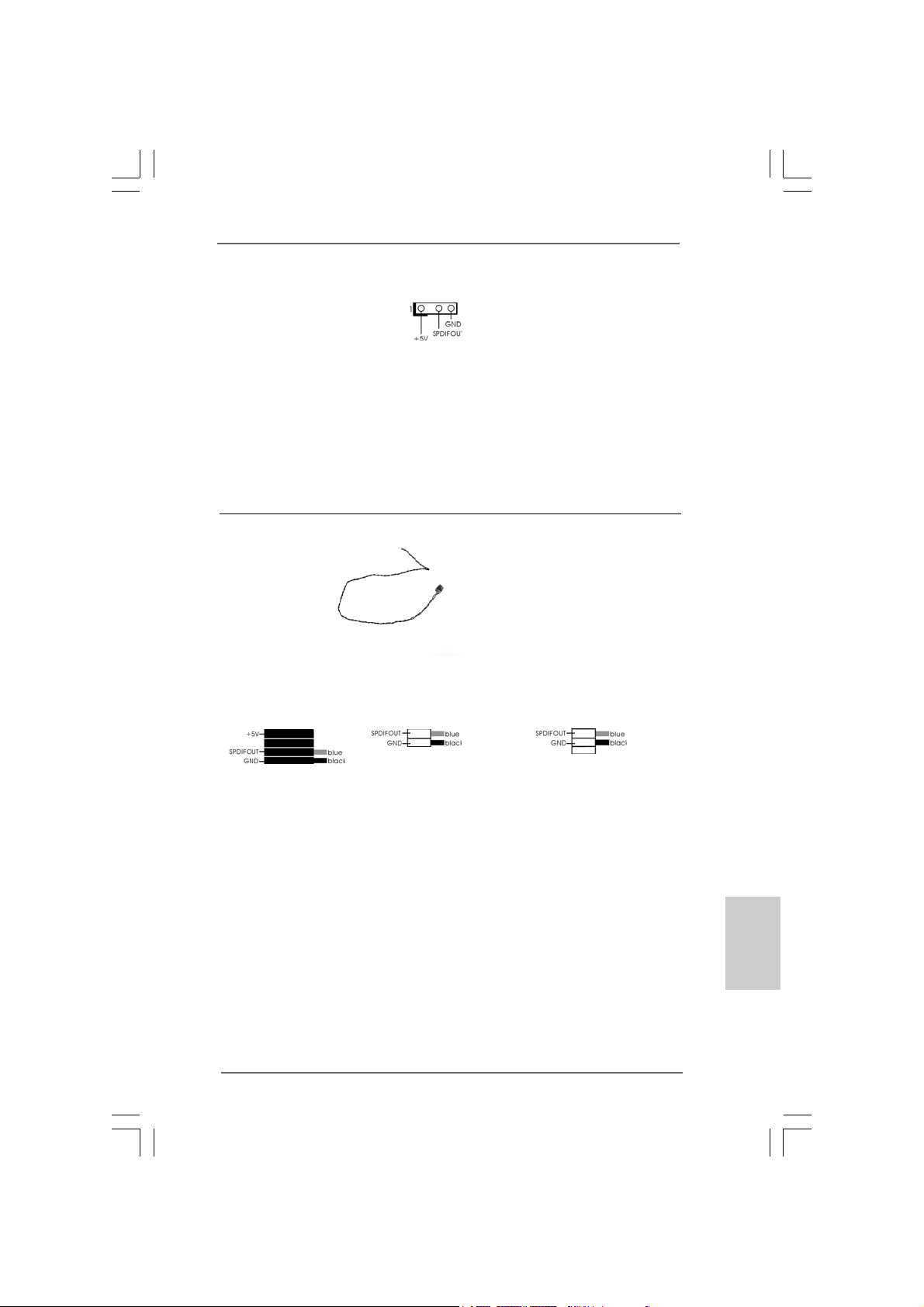
12
1
8 5
4 1
HDMI_SPDIF-Anschluss Der HDMI_SPDIF-Anschluss
(HDMI_SPDIF1, dreipolig) stellt einen SPDIF-
(siehe S.2 - No. 29) Audioausgang für eine HDMI-
VGA-Karte zur V erfügung und
ermöglicht den Anschluss von
24
HDMI-Digitalgeräten wie
Fernsehgeräten, Projektoren,
LCD-Geräten an das System.
Bitte verbinden Sie den
HDMI_SPDIF-Anschluss der
13
HDMI-VGA-Karte mit diese m
Anschluss.
HDMI_SPDIF-Kabel Bitte verbinden Sie das
(Option) schwarze Ende (A) des
C
B
A
HDMI_SPDIF-Kabels mit dem
HDMI_SPDIF-Anschluss am
Motherboard. Schließen Sie
dann das weiße Ende (B oder
C) des HDMI_SPDIF-Kabels an
den HDMI_SPDIF-Anschluss der
HDMI-VGA-Karte an.
A. Schwarzes Ende B. Weißes Ende (zweipolig) C. Weißes Ende (dreipolig)
ASRock P55 Pro Motherboard
5353
53
5353
DeutschDeutsch
DeutschDeutsch
Deutsch
Page 54
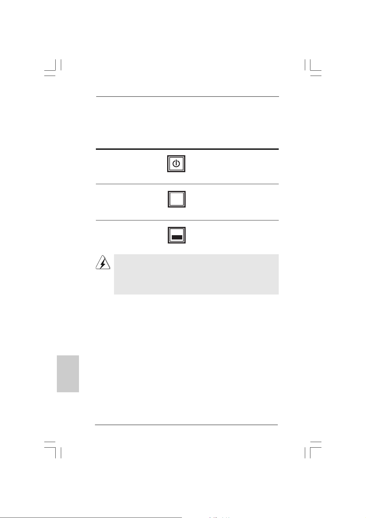
2.92.9
SchnellschalterSchnellschalter
2.9
Schnellschalter
2.92.9
SchnellschalterSchnellschalter
Dieses Motherboard besitzt drei Schnellschalter: Netzschalter, Rücksetzschalter
(Reset) und CMOS löschen-Schalter, mit denen Benutzer das System schnell ein-/
ausschalten oder zurücksetzen oder die CMOS-Werte löschen können.
Netzschalter Der Netzschalter ist ein
(PWRBTN) Schnellschalter, mit dem
(siehe S.2 - No. 20) Benutzer das System schnell
ein-/ausschalten können.
Rücksetzschalter (Reset) Der Rücksetzschalter (Reset) ist
(RSTBTN) ein Schnellschalter, mit dem
(siehe S.2 - No. 18) Benutzer das System schnell
RESET
zurücksetzen können.
Deutsch
DeutschDeutsch
DeutschDeutsch
CMOS löschen-Schalter Der CMOS löschen-Schalter ist
(CLRCBTN) ein Schnellschalter, mit dem
(siehe S.2 - No. 17) Benutzer die CMOS-Werte
clr
CMOS
schnell löschen können.
Es ist Ihnen bei Einrichtung des Systemkennworts nicht gestattet, die
Schalterfunktion Clear CMOS (CMOS löschen) zu verwenden. Wenn Sie die
CMOS-Werte entfernen möchten, müssen Sie zuerst Ihr Systemkennwort
entfernen, oder Sie können sich stattdessen auch auf die Beschreibung
“Clear CMOS jumper” (CMOS löschen-Jumper) auf Seite 47 beziehen.
5454
54
5454
ASRock P55 Pro Motherboard
Page 55

2.102.10
Debug-LEDDebug-LED
2.10
Debug-LED
2.102.10
Debug-LEDDebug-LED
Die integrierte Debug-LED liefert Codeinformationen, die eine Fehlerbehebung
erleichtern. Siehe die Abbildungen auf den Seiten 27, 28 und 29 zum Ablesen der
Debug-LED-Codes.
2.112.11
TT
2.11
2.112.11
Zur Treiberinstallation Sie bitte die Unterstützungs-CD in Ihr optisches Laufwerk
ein. Anschließend werden die mit Ihrem System kompatiblen Treiber automatisch
erkannt und auf dem Bildschirm angezeigt. Zur Installation der nötigen Treiber
gehen Sie bitte der Reihe nach von oben nach unten vor. Nur so können die von
Ihnen installierten Treiber richtig arbeiten.
reiberinstallationreiberinstallation
T
reiberinstallation
TT
reiberinstallationreiberinstallation
®®
®
2.122.12
Windows Windows
2.12
Windows
2.122.12
Windows Windows
RAID RAID
RAID
RAID RAID
Wenn Sie die Betriebssysteme Windows® XP / XP 64-bit / VistaTM / VistaTM 64-bit auf
Ihren SATA- / SA TAII-Festplatten mit RAID-Funktionalität installieren möchten,
entnehmen Sie die detaillierten Schritte bitte dem Dokument, das Sie unter folgendem
Pfad auf der Unterstützungs-CD finden:
..\ RAID Installation Guide
2.132.13
WindowsWindows
2.13
Windows
2.132.13
WindowsWindows
ohne RAIDohne RAID
ohne RAID
ohne RAIDohne RAID
Wenn Sie Windows® XP / XP 64-Bit / VistaTM / VistaTM 64-Bit ohne RAIDFunktionalität auf Ihren SATA / SATAII-Festplatten in stallieren, da nn f olgen Sie bitte je
nach dem zu installierenden Betriebssyste m den f olgenden Schritten.
2.13.1 Windows2.13.1 Windows
2.13.1 Windows
2.13.1 Windows2.13.1 Windows
installieren installieren
installieren
installieren installieren
Wenn Sie Windows® XP / XP 64-Bit ohne RAID-Funktionalität auf Ihren SATA / SAT AIIFestplatten installieren, gehen Sie bitte wie folgt vor.
Verwendung von SATA / SATAII-Festplatten ohne NCQ-Funktionen
SCHRITT 1: BIOS einrichten.
A. Rufen Sie das BIOS SETUP UTILITY auf, wählen Sie den „Adva nced“ Bildschirm (Erweitert), dann „Storage Configuration“.
B. Stellen Sie “SATAII Operation Mode” auf [IDE].
SCHRITT 2: Installieren Sie Windows® XP / XP 64-Bit in Ihrem System.
®®
XP / XP 64-Bit / Vista XP / XP 64-Bit / Vista
XP / XP 64-Bit / Vista
XP / XP 64-Bit / Vista XP / XP 64-Bit / Vista
-F-F
unktionalität installierenunktionalität installieren
-F
unktionalität installieren
-F-F
unktionalität installierenunktionalität installieren
®®
®
®®
/ XP / XP 64-Bit / Vista / XP / XP 64-Bit / Vista
/ XP / XP 64-Bit / Vista
/ XP / XP 64-Bit / Vista / XP / XP 64-Bit / Vista
-F-F
unktionalität installierenunktionalität installieren
-F
unktionalität installieren
-F-F
unktionalität installierenunktionalität installieren
®®
®
®®
XP / XP 64-Bit ohne RAID-Funktionalität XP / XP 64-Bit ohne RAID-Funktionalität
XP / XP 64-Bit ohne RAID-Funktionalität
XP / XP 64-Bit ohne RAID-Funktionalität XP / XP 64-Bit ohne RAID-Funktionalität
TMTM
TM
TMTM
/ Vista / Vista
/ Vista
/ Vista / Vista
TMTM
TM
TMTM
/ Vista / Vista
/ Vista
/ Vista / Vista
TMTM
TM
TMTM
64-Bit mit 64-Bit mit
64-Bit mit
64-Bit mit 64-Bit mit
TMTM
TM
TMTM
64-Bit 64-Bit
64-Bit
64-Bit 64-Bit
DeutschDeutsch
DeutschDeutsch
Deutsch
ASRock P55 Pro Motherboard
5555
55
5555
Page 56

Deutsch
DeutschDeutsch
DeutschDeutsch
®®
®
2.13.2 Windows2.13.2 Windows
2.13.2 Windows
2.13.2 Windows2.13.2 Windows
Funktionalität installieren Funktionalität installieren
Funktionalität installieren
Funktionalität installieren Funktionalität installieren
Wenn Sie Windows® VistaTM / VistaTM 64-Bit ohne RAID-Funktionalität auf Ihren SATA
/ SATAII-Festplatten installieren, gehen Sie bitte wie folgt vor.
Verwendung von SATA / SATAII-Festplatten ohne NCQ-Funktionen
SCHRITT 1: BIOS einrichten.
A. Rufen Sie das BIOS SETUP UTILITY auf, wählen Sie den „Advanced“ Bildschirm (Erweitert), dann „Storage Configuration“.
B. Stellen Sie “SATAII Operation Mode” auf [IDE].
SCHRITT 2: Installieren Sie Windows® VistaTM / VistaTM 64-Bit in Ihrem
System.
Verwendung von SATA / SATAII-Festplatten mit NCQ-Funktionen
SCHRITT 1: BIOS einrichten.
A. Rufen Sie das BIOS SETUP UTILITY auf, wählen Sie den „Advanced“ Bildschirm (Erweitert), dann „Storage Configuration“.
B. Stellen Sie “SATAII Operation Mode” auf [AHCI].
SCHRITT 2: Installieren Sie Windows® VistaTM / VistaTM 64-Bit in Ihrem
System.
Legen Sie Windows® VistaTM / VistaTM 64-Bit optische Disc in das optische
Laufwerk ein, um Ihr System zu starten. Folgen Sie anschließend den
Anweisungen, um das Windows® VistaTM / VistaTM 64-Bit Betriebssystem auf
Ihrem System zu installieren. Wenn die Frage “Wo möchten Sie Windows
installieren?” erscheint, legen Sie bitte
die ASRock Support CD in Ihr optisches Laufwerk ein. Klicken Sie anschließend die
“Treiber laden”-Schaltfläche link s unten, um die Intel® AHCI-T reiber zu installieren. Die
Intel® AHCI-T reiber befinden sich in de m folgenden V erzeichnis auf der Support CD:
.. \ I386 (Für Windows® VistaTM-Benutzer)
.. \ AMD64 (Für Windows® VistaTM 64-Bit Benutzer)
Legen Sie danach noch einmal die Windows® VistaTM / VistaTM 64-Bit optische Disc in
das optische Laufwerk, um die Installation f ortzusetzen.
®®
Vista Vista
Vista
Vista Vista
TMTM
TM
TMTM
/ Vista / Vista
/ Vista
/ Vista / Vista
TMTM
TM
TMTM
64-Bit ohne RAID- 64-Bit ohne RAID-
64-Bit ohne RAID-
64-Bit ohne RAID- 64-Bit ohne RAID-
5656
56
5656
ASRock P55 Pro Motherboard
Page 57

3. BIOS-Information3. BIOS-Information
3. BIOS-Information
3. BIOS-Information3. BIOS-Information
Das Flash Memory dieses Motherboards speichert das Setup-Utility. Drücken Sie
<F2> während des POST (Power-On-Self-Test) um ins Setup zu gela ngen, a n son sten
werden die Testroutinen weiter abgearbeitet. Wenn Sie ins Setup gelangen wollen,
nachdem der POST durchgeführt wurde, müssen Sie das System über die
Tastenkombination <Ctrl> + <Alt> + <Delete> oder den Reset-Knopf auf der
Gehäusevorderseite, neu starten. Natürlich können Sie einen Neustart auch
durchführen, indem Sie das System kurz ab- und danach wieder anschalten.
Das Setup-Programm ist für eine bequeme Bedienung entwickelt worden. Es ist
ein menügesteuertes Programm, in dem Sie durch unterschiedliche Untermenüs
scrollen und die vorab festgelegten Optionen auswählen können. Für detaillierte
Informationen zum BIOS-Setup, siehe bitte das Benutzerhandbuch (PDF Datei) auf
der Support CD.
4. Sof4. Sof
4. Sof
4. Sof4. Sof
Dieses Motherboard unterstützt eine Reiche von Microsoft® Windows
Betriebssystemen: XP / XP 64-Bit / VistaTM / Vista
Motherboard beigefügte Support-CD enthält hilfreiche Software, Treiber und
Hilfsprogramme, mit denen Sie die Funktionen Ihres Motherboards verbessern
können Legen Sie die Support-CD zunächst in Ihr CD-ROM-Laufwerk ein. Der
Willkommensbildschirm mit den Installationsmenüs der CD wird automatisch
aufgerufen, wenn Sie die “Autorun”-Funktion Ihres Systems aktiviert haben.
Erscheint der Wilkommensbildschirm nicht, so “doppelklicken” Sie bitte auf das File
ASSETUP.EXE im BIN-Verze ichnis der Support-CD, um die Menüs aufzurufen.
Das Setup-Progra mm soll es Ihnen so le icht wie möglich ma chen. Es ist menügesteuert,
d.h. Sie können in den verschiedenen Untermenüs Ihre Auswahl treffen und die
Programme werden dann automatisch installiert.
tware Supportware Suppor
tware Suppor
tware Supportware Suppor
t CD informationt CD information
t CD information
t CD informationt CD information
®
TM
64-Bit / Win7. Die Ihrem
DeutschDeutsch
DeutschDeutsch
Deutsch
ASRock P55 Pro Motherboard
5757
57
5757
Page 58
1. Introduction1. Introduction
1. Introduction
1. Introduction1. Introduction
Merci pour votre achat d’une carte mère ASRock P55 Pro, une carte mère très fiable
produite selon les critères de qualité rigoureux de ASRock. Elle offre des performances excellentes et une conception robuste conformément à l’engagement
d’ASRock sur la qualité et la fiabilité au long terme.
Ce Guide d’installation rapide présente la carte mère et constitue un guide
d’installation pas à pas. Des informations plus détaillées concernant la carte mère
pourront être trouvées dans le ma nuel l’utilisateur qui se trouve sur le CD d’assista nce.
Les spécifications de la carte mère et le BIOS ayant pu être mis à
jour, le contenu de ce manuel est sujet à des changements sans
notification. Au cas où n’importe qu’elle modification intervenait sur ce
manuel, la version mise à jour serait disponible sur le site web
ASRock sans nouvel avis. Vous trouverez les listes de prise en
charge des cartes VGA et CPU également sur le site Web ASRock.
Site web ASRock, http://www.asrock.com
Si vous avez besoin de support technique en relation avec cette carte
mère, veuillez consulter notre site Web pour de plus amples
informations particulières au modèle que vous utilisez.
www.asrock.com/support/index.asp
1.1 Contenu du paquet1.1 Contenu du paquet
1.1 Contenu du paquet
1.1 Contenu du paquet1.1 Contenu du paquet
Carte mère ASRock P55 Pro
(Facteur de forme ATX: 12.0 pouces x 8.6 pouces, 30.5 cm x 21.8 cm)
Guide d’installation rapide ASRock P55 Pro
CD de soutien ASRock P55 Pro
Un câble ruba n IDE Ultra ATA 66/100/133 80 conducteurs
Un câble ruba n pour un lecteur de dis quettes 3,5 pouces
Quatre câbles de données de série ATA (SATA) (en option)
Un câble d’alimentation de série ATA (SATA) HDD (en option)
Un I/O Pa nel Shield
Français
FrançaisFrançais
FrançaisFrançais
5858
58
5858
ASRock P55 Pro Motherboard
Page 59
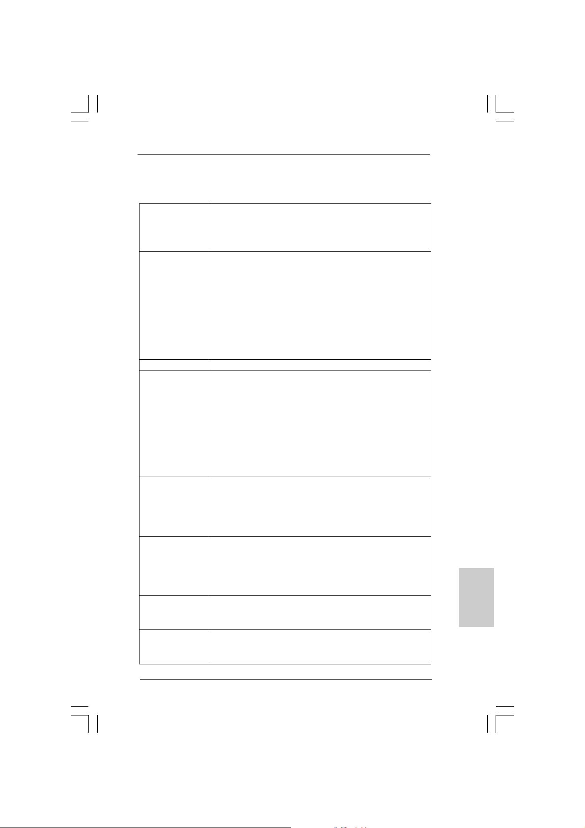
1.21.2
SpécificationsSpécifications
1.2
Spécifications
1.21.2
SpécificationsSpécifications
Format - Facteur de forme A TX:
12.0 pouces x 8.6 pouces, 30.5 cm x 21.8 cm
- Accessoire s de Carte mère (condensateurs 100% polymère
conducteur de haute qualité fabriqué au Ja pon)
CPU - Prend en charge les processeurs Intel® CoreTM i7 et Intel
CoreTM i5 sous le package LGA1156
- Conception avancée V8 + 2 Power Phase
- Prend en charge la technologie Intel® Turbo Boost
- Prise en charge de la technologie Hyper-Threading
(voir ATTENTION 1)
- Prend en charge la technologie Untied Overclocking
(voir ATTENTION 2)
- Prise en charge de la technologie EM64T par le CPU
Chipsets - Intel® P55
Mémoire - Compatible avec la Technologie de Mémoire à Canal Double
(voir ATTENTION 3)
- 4 x slots DIMM DDR3
- Supporter DDR3 2600+(OC)/2133(OC)/1866(OC)/1600/1333/
1066 non-ECC, sans amortissement mémoire
- Capacité maxi de mémoire système: 16GB
(voir ATTENTION 4)
- Prend en charge le profil de mémoire extrême Intel® (XMP)
(voir ATTENTION 5)
Slot d’extension - 1 slot PCI Express 2.0 x16 (en mode x16)
- 1 slot PCI Express 2.0 x16 (en mode x4, 2,5GT/s)
- 2 slots PCI Express 2.0 x1 (2,5GT/s)
- 2 x slots PCI
- Prend en charge ATITM CrossFireXTM et Quad CrossFireX
Audio - 7,1 CH Windows® VistaTM Premium niveau HD Audio avec
protection de contenu
- DAC avec une gamme dynamique 110dB
(ALC890 Audio Codec)
- Prise en charge de l’audio Premium Blu-ray
LAN - PCIE x1 Gigabit LAN 10/100/1000 Mb/s
- Realtek RTL81 11DL
- Support du Wake-On-LAN
Panneau arrière I/O Panel
- 1 x port souris PS/2
- 1 x port clavier PS/2
®
TM
çaisçais
çaisçais
çais
FranFran
FranFran
Fran
ASRock P55 Pro Motherboard
5959
59
5959
Page 60
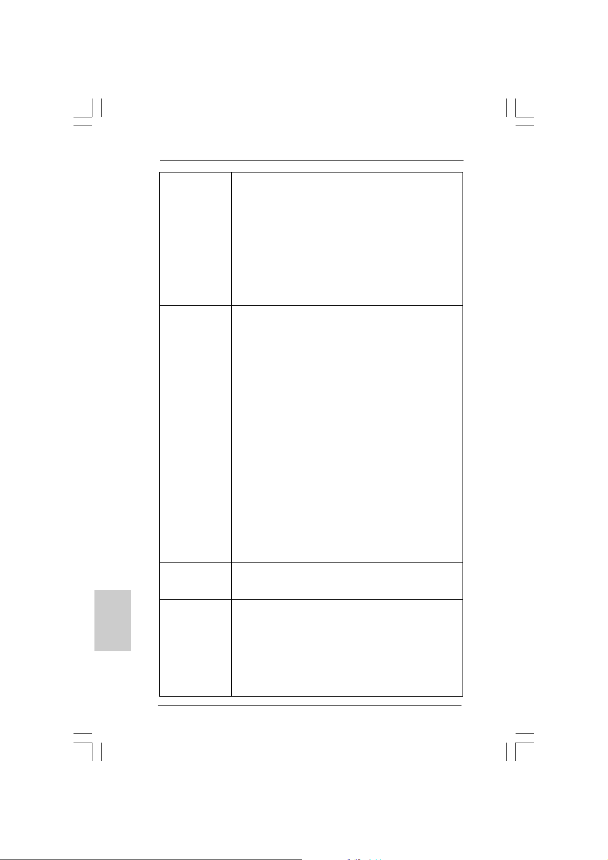
Français
FrançaisFrançais
FrançaisFrançais
6060
60
6060
- 1 x Port de sortie coaxial SPDIF
- 1 x Port de sortie optique SPDIF
- 6 x ports USB 2.0 par défaut
- 2 x Connecteur eSA TAII/USB alimenté
- 1 x port LAN RJ-45 avec LED (ACT/LED CLIGNOT ANTE et
LED VITESSE)
- 1 x port IEEE 1394
- 1 x interrupteur d’effacement du CMOS avec LED
- Prise HD Audio: Haut-parleur latéral / Haut-parleur arrière /
Central /Basses / Entrée Ligne / Haut-parleur frontal /
Microphone (voir ATTENTION 6)
Connecteurs - 6 x connecteurs SATAII, prennent en charge un taux de
transfert de données pouvant aller jusqu’à 3.0Go/s, supporte
RAID (RAID 0, RAID 1,RAID 10, RAID 5 et mémoire à sélection
matricielle), NCQ, AHCI et “Hot-Plug” (Connexion à chaud)
(voir ATTENTION 7)
- 1 x ATA133 IDE connecteurs
(prend en charge jusqu’à 2 périphériques IDE)
- 1 x Port Dis quette
- 1 x En-tête du module infrarouge
- 1 x En-tête de port COM
- 1 x Connecteur HDMI_SPDIF
- 1 x Connecteur IEEE 1394
- 1 x connecteur TPM
- Connecteur pour processeur/châssis/ventilateur
- br. 24 connecteur d’ali mentation ATX
- br. 8 connecteur d’alimentation 12V ATX
- Connecteurs audio internes
- Connecteur audio panneau ava nt
- 3 x En-tête USB 2.0 (prendre en charge 6 ports USB 2.0
supplémentaires) (voir ATTENTION 8)
- 1 x Dr. Debug (LED de débogage à 7 segments)
Interrupteur - 1 x interrupteur d’effacement du CMOS avec LED
rapide - 1 x interrupteur d’alimentation avec LED
- 1 x interrupteur de réinitialisation avec LED
BIOS - 16Mb BIOS AMI
- BIOS AMI
- Support du “Plug and Play”
- Compatible pour événements de réveil ACPI 1.1
- Gestion jumperless
- Support SMBIOS 2.3.1
- CPU, VCCM, SB, VTT, VCCM REF, PCH_PLL Tension
Multi-ajustement
ASRock P55 Pro Motherboard
Page 61
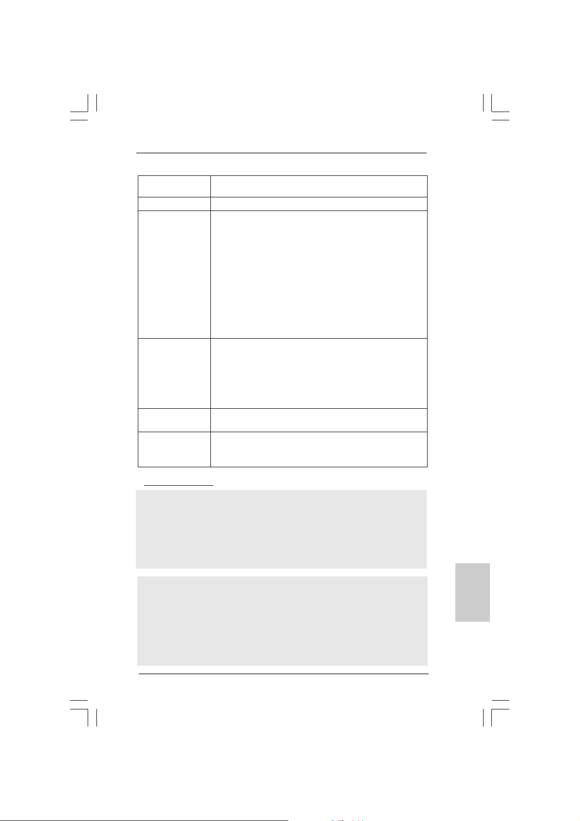
- Supporter I. O. T. (Technologie d’Overclocking Intelligent)
- Prise en charge du Smart BIOS
CD d’assistance - Pilotes, utilitaires, logiciel anti-virus (Version d’essai)
Caractéristique - Tuner ASRock OC (voir ATTENTION 9)
unique - Économiseur d’énergie intelligent (voir ATTENTION 10)
- l'Instant Boot
- ASRock Instant Flash (voir ATTENTION 11)
- L’accélérateur hybride:
- Contrôle direct de la fréquence CPU
(voir ATTENTION 12)
- ASRock U-COP (voir ATTENTION 13)
- Garde d’échec au démarrage (B.F.G.)
- Combo Cooler Option (C.C.O.) (voir A TTENTION 14)
- DEL veilleuse
Surveillance - Contrôle de la température CPU
système - Mesure de température de la carte mère
- Tachéomètre ventilateur processeur/châssis/ventilateur
- Ventilateur silencieux d’unité centrale
- Commande de ventilateur CPU/boîtier à plusieurs vitesses
- Monitoring de la tension: +12V, +5V, +3.3V, Vcore
OS - Microsoft® Windows® XP / XP 64-bit / VistaTM / Vista
/ Win7
Certifications - FCC, CE, WHQL
- Prêt pour EuP (alimentation Prêt pour EuP requise)
(voir ATTENTION 15)
* Pour de plus amples informations sur les produits, s’il vous plaît visitez notre site web:
http://www.asrock.com
A TTENTION
Il est important que vous réalisiez qu’il y a un certain risque à effectuer l’overclocking, y
compris ajuster les réglages du BIOS, appliquer la technologie Untied Overclocking, ou
utiliser des outils de tiers pour l’overclocking. L’overclocking peut affecter la stabilité de
votre système, ou même causer des dommages aux composants et dispositifs de votre
système. Si vous le faites, c’est à vos frais et vos propres risques. Nous ne sommes
pas responsables des dommages possibles causés par l’overclocking.
TM
64-bit
ATTENTION!
1. En ce qui concerne le paramétrage “Hyper-Threading Technology”,
veuillez consulter la page 55 du manuel de l’utilisateur sur le CD
technique.
2. Cette carte mère prend en charge la technologie Untied Overclocking.
Veuillez lire “La technologie de surcadençage à la volée” à la page 31
pour plus d’informations.
ASRock P55 Pro Motherboard
6161
61
6161
çaisçais
çaisçais
çais
FranFran
FranFran
Fran
Page 62
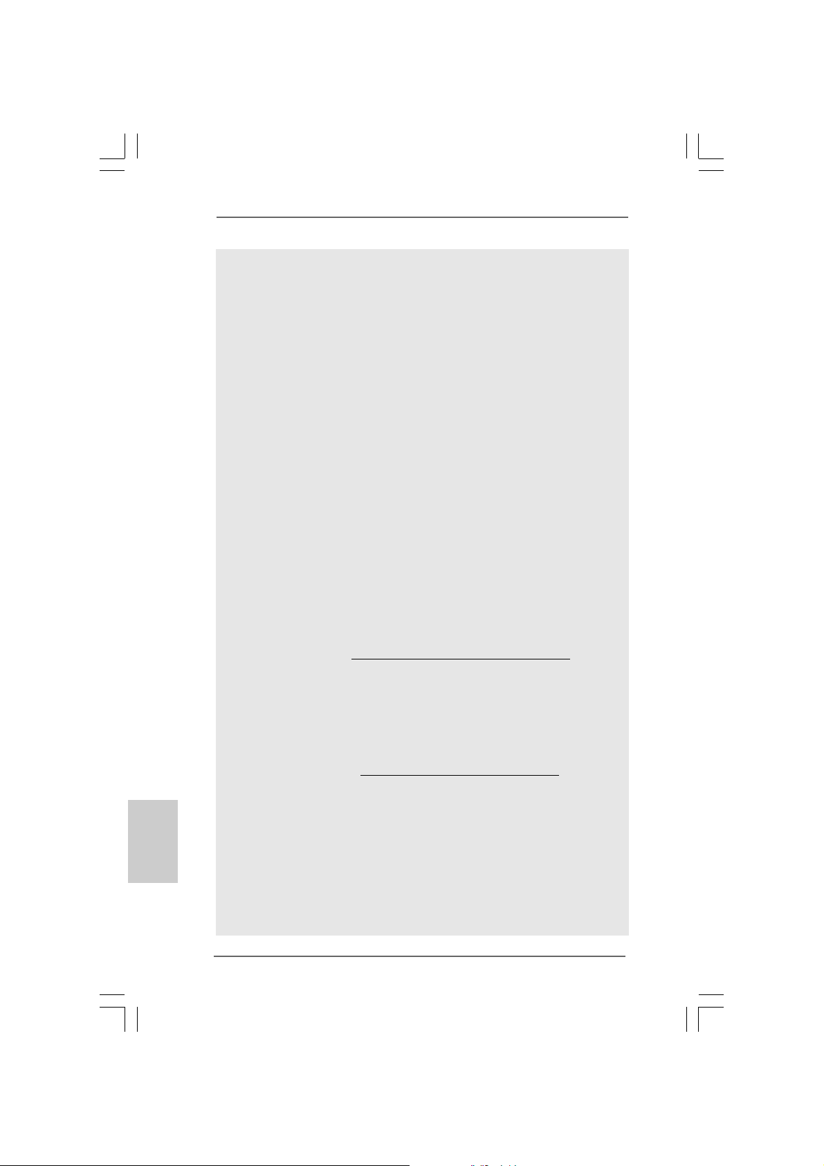
Français
FrançaisFrançais
FrançaisFrançais
3. Cette carte mère supporte la Technologie de Mémoire à Canal Double.
Avant d’intégrer la Technologie de Mémoire à Canal Double, assurezvous de bien lire le guide d’installation des modules mémoire en page 68
pour réaliser une installation correcte.
4. Du fait des limites du système d’exploitation, la taille mémoire réelle
réservée au système pourra être inférieure à 4 Go sous Windows® XP et
Windows® VistaTM. Avec Windows® XP 64 bits et Windows® VistaTM 64 bits
avec CPU 64 bits, il n’y a pas ce genre de limitation.
5. Pour les CPU qui prennent en charge seulement jusqu’à la DDR3 1333, le
XMP DDR3 1600 est pris en charge par overclockage.
6. Pour l’entrée microphone, cette carte mère supporte les deux modes
stéréo et mono. Pour la sortie audio, cette carte mère supporte les
modes 2-canaux, 4-canaux, 6-canaux et 8-canaux. Veuillez vous
référer au tableau en page 3 pour effectuer la bonne connexion.
7. Avant d’installer le disque dur SATAII au connecteur SATAII, veuillez lire
le Guide « Installation du dis que dur SATAII » à la page 36 du « Manuel
de l’utilisateur » qui se trouve sur le CD de support pour régler votre
lecteur de disque dur SATAII au mode SATAII. Vous pouvez aussi
directement connecter le disque dur SATA au connecteur SATAII.
8. La gestion de l’alimentation pour l’USB 2.0 fonctionne bien sous
Microsoft® Windows® VistaTM 64-bit/ VistaTM / XP 64-bit / XP SP1; SP2.
9. Il s’agit d’un usage facile ASRock overclocking outil qui vous permet de
surveiller votre système en fonction de la monitrice de matériel et
overclocker vos périphériques de matériels pour obtenir les
meilleures performances du système sous environnement
Windows®. S’il vous plaît visitez notre site web pour le
fonctionnement des procédures de Tuner ASRock OC.
ASRock website: http://www.asrock.com/feature/OCTuner/index.htm
10. Comprenant une conception matérielle et logicielle propriétaire avancée,
Intelligent Energy Saver est une technologie révolutionnaire qui offre
des gains d’énergie incomparables. En d’autres termes, il est capable
d’apporter des économies d’énergie exce ptionnelle s et d’améliorer
l’efficacité énergétique sans sacrifier aux performances de calcul.
Veuillez visiter notre site Web pour les procédures d’utilisation
d’Intelligent Energy Saver.
Site Web ASRock : http://www.asrock.com/feature/IES/index.html
11. O ASRock Instant Flash é um utilitário de flash do BIOS incorporado na
memória Flash ROM. Esta prática ferramenta de actualização do BIOS
permite-lhe actualizar o BIOS do sistema sem necessitar de entrar nos
sistemas operativos, como o MS-DOS ou o Windows®. Com este
utilitário, poderá premir a tecla <F6> durante o teste de arranque POST
ou premir a tecla <F2> para exibir o menu de configuração do BIOS
para aceder ao ASRock Instant Flash. Execute esta ferramenta para
guardar o novo ficheiro de BIOS numa unidade flash USB, numa
disquete ou num disco rígido, em seguida, poderá actualizar o BIOS
6262
62
6262
ASRock P55 Pro Motherboard
Page 63

com apenas alguns cliques sem ter de utilizar outra disquete ou outro
complicado utilitário de flash. Note que a unidade flash USB ou a
unidade de disco rígido devem utilizar o sistema de ficheiros FAT32/16/
12.
12. Même si cette carte mère offre un contrôle sans souci, il n’est pas
recommandé d’y appliquer un over clocking. Des fréquences de bus CPU
autres que celles recommandées risquent de rendre le système instable
ou d’endommager le CPU et la carte mère.
13. Lorsqu’une surchauffe du CPU est détectée, le système s’arrête
automatiquement. Avant de redémarrer le système, veuillez vérifier que
le ventilateur d’UC sur la carte mère fonctionne correctement et débranchez
le cordon d’alimentation, puis rebranchez-le. Pour améliorer la dissipation
de la chaleur, n’oubliez pas de mettre de la pâte thermique entre le CPU le
dissipateur lors de l’installation du PC.
14. Le Combo Cooler Option (C.C.O.) offre un choix flexible pour adopter
deux types différents de refroidisseur sde CPU, les sockets LGA 775 et
LGA 1156. Veuillez noter que tous les ventilateurs de CPU 775 ne peuvent
pas être utilisés.
15. EuP, qui signifie Energy Using Product (Produit Utilisant de l’Energie), est
une disposition établie par l’Union Européenne pour définir la consommation
de courant pour le système entier. Conformément à la norme EuP, le
courant CA total du système entier doit être inférieur à 1 W en mode
d’arrêt. Pour être conforme à la norme EuP, une carte mère EuP et une
alimentation EuP sont requises. Selon les suggestions d’Intel’, l’alimentation
électrique EuP doit correspondre à la norme, qui est que l’efficacité électrique
de 5v en mode de veille doit être supérieure à 50% pour 100 mA de
consommation de courant. Pour choisir une alimentation électrique conforme
à la norme EuP, nous vous recommandons de consulter votre fournisseur
de courant pour plus de détails.
ASRock P55 Pro Motherboard
6363
63
6363
çaisçais
çaisçais
çais
FranFran
FranFran
Fran
Page 64
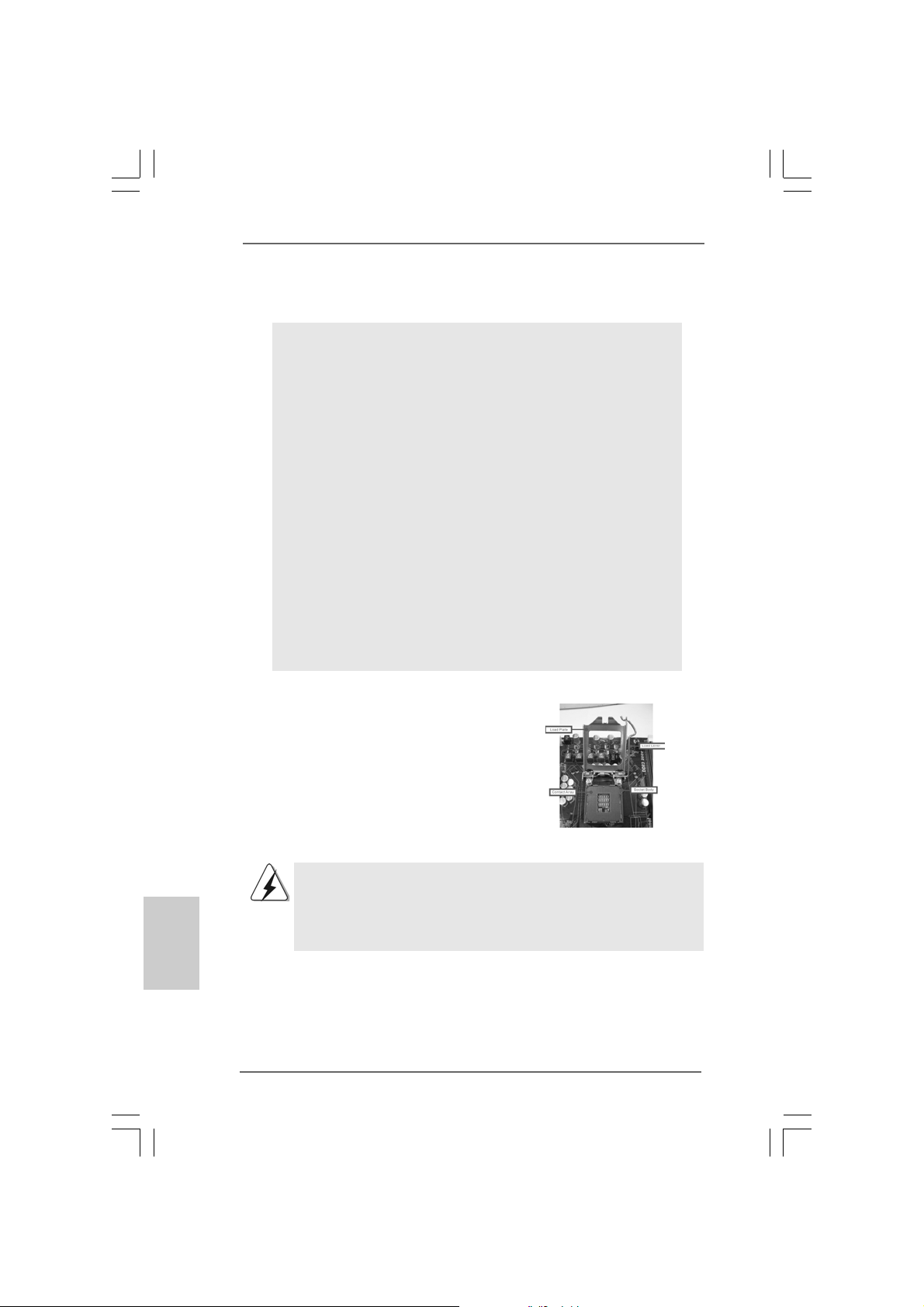
2. Installation2. Installation
2. Installation
2. Installation2. Installation
Précautions à observer avant l’installationPrécautions à observer avant l’installation
Précautions à observer avant l’installation
Précautions à observer avant l’installationPrécautions à observer avant l’installation
Veuillez tenir compte des précautions suivantes avant l’installation
des composants ou tout réglage de la carte mère.
1. Débranchez le câble d’alimentation de la prise secteur avant de toucher
à tout composant. En ne le faisant pas, vous pouvez sérieusement
endommager la carte mère, les périphériques et/ou les composants.
2. Pour éviter d’endommager les composants de la carte mère du fait de
l’électricité statique, ne posez JAMAIS votre carte mère directement sur
de la moquette ou sur un tapis. N’oubliez pas d’utiliser un bracelet
antistatique ou de toucher un objet relié à la masse avant de manipuler
les composants.
3. Tenez les composants par les bords et ne touchez pas les circuits
intégrés.
4. A chaque désinstallation de composant, placez-le sur un support
antistatique ou dans son sachet d’origine.
5. Lorsque vous placez les vis dans les orifices pour vis pour fixer la carte
mère sur le châssis, ne serrez pas trop les vis ! Vous risquez sinon
d’endommager la carte mère.
2.1 Installation du CPU2.1 Installation du CPU
2.1 Installation du CPU
2.1 Installation du CPU2.1 Installation du CPU
Pour l’installation du processeur Intel 1156
broches, veuillez suivre la procédure
ci-dessous.
(Plaque de
chargement)
Français
FrançaisFrançais
FrançaisFrançais
6464
64
6464
(Barrette de
contact)
Vue d’ensemble du socket 1156 broches
Avant d’insérer le processeur 1156 broches dans le socket, veuillez
vérifier que la surface du processeur est bien propre, et qu’il n’y a
aucune broche tordue sur le socket. Si c’est le cas, ne forcez pas
pour insérer le processeur dans le socket. Sinon, le processeur
sera gravement endommagé.
ASRock P55 Pro Motherboard
(Corps du
socket)
Page 65
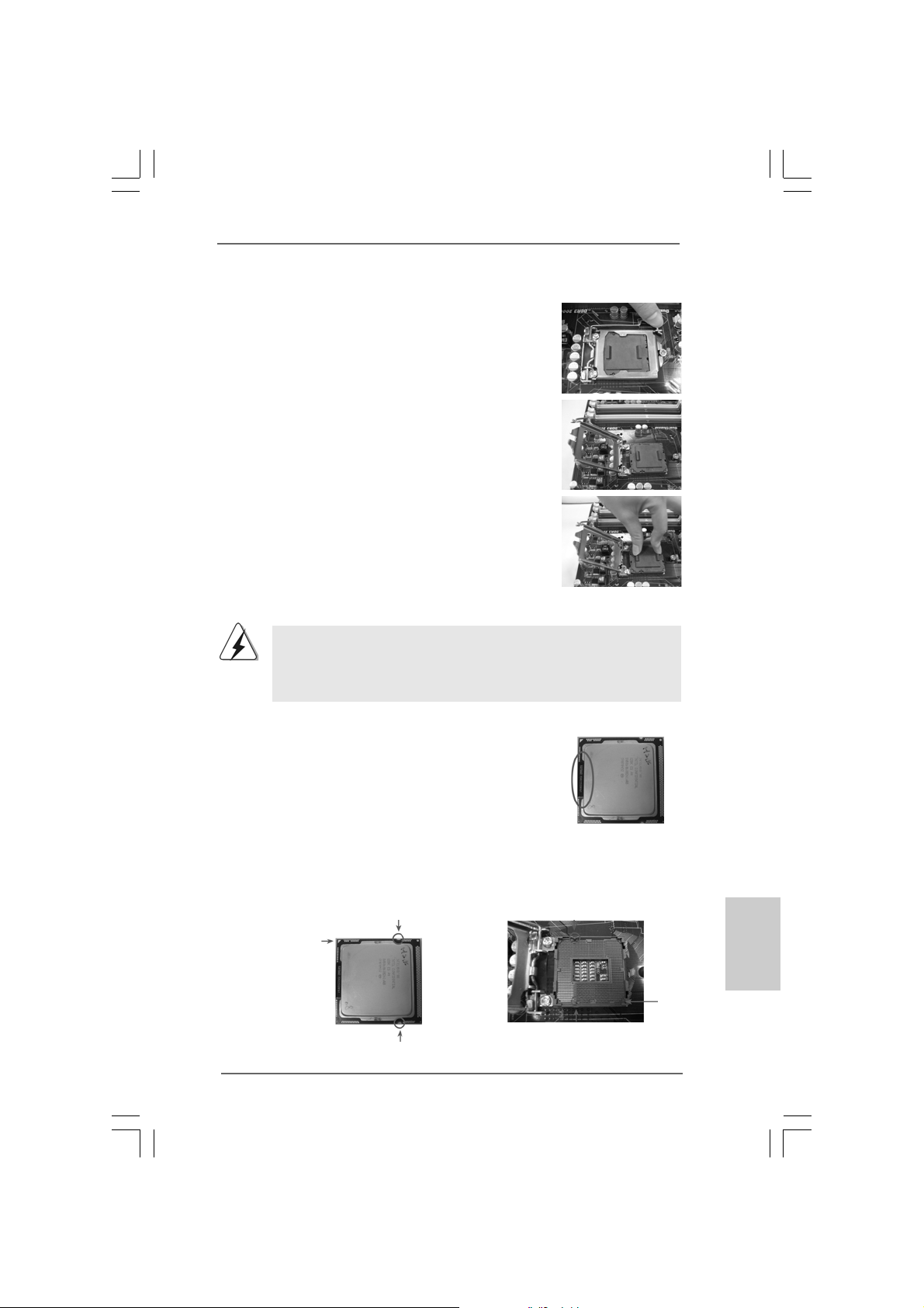
Etape 1. Ouvrez le socle :
Etape 1-1. Dégagez le levier en appuyant sur le
crochet et en le faisant ressortir
pour dégager la languette de
retenue.
Etape 1-2. Faites tourner le levier de
chargement en position ouverte
maximum à 135 degrés.
Etape 1-3. Faites pivoter la plaque de
chargement pour l’ouvrir au
maximum à environ 100 degrés.
Etape 2. Enlevez le capuchon PnP (Pick et Place).
1. Il est recommandé d’utiliser la languette du capuchon ; évitez
de faire sortir le capuchon PnP.
2. Ce capuchon doit être mis en place si vous renvoyez la carte
mère pour service après vente.
Etape 3. Insérez le processeur 1156 broches :
Etape 3-1. Tenez le processeur par ses bords
là où se trouvent des lignes noires.
Ligne noire
Etape 3-2. Orientez le paquet avec le
dissipateur thermique intégré (IHS)
vers le haut. Repérez la broche 1 et
les deux encoches d’orientation.
Encoche d’orientation
broche 1
Encoche d’orientation
Processeur 1156 broches
ASRock P55 Pro Motherboard
Détrompeur
Détrompeur
Socket 1156 broches
broche 1
6565
65
6565
çaisçais
çaisçais
çais
FranFran
FranFran
Fran
Page 66
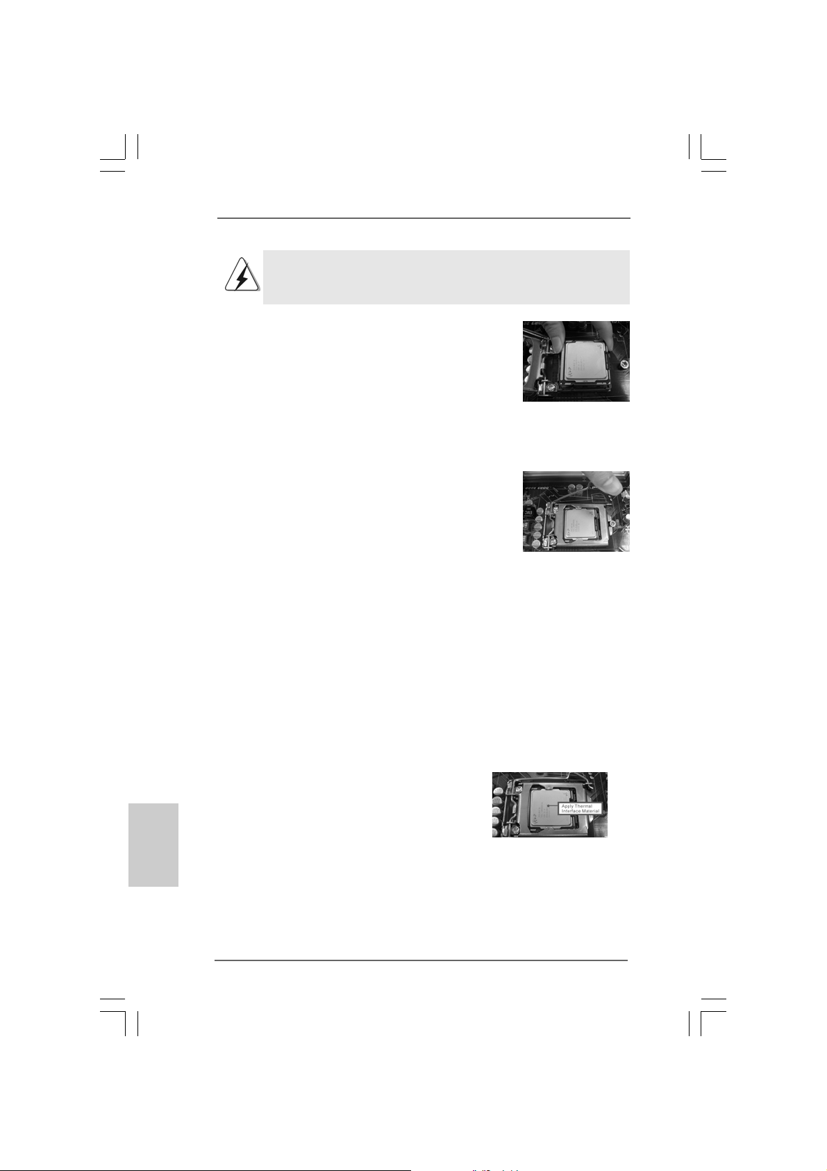
Pour une insertion correcte, veuillez vérifier que vous faites bien
correspondre les deux encoches d’orientation sur le processeur
avec les deux détrompeurs du socket
Etape 3-3. Mettez soigneuse ment en place le
processeur dans le socle en un
mouvement strictement vertical.
Etape 3-4. Vérifiez que le proce sseur est bien
installé dans le socle et que les
encoches d’orientation sont dans la
bonne position.
Etape 4. Refermez le socle :
Etape 4-1. Faites pivoter la plaque de
chargement sur l’IHS.
Etape 4-2. Tout en appuyant doucement sur
la plaque de chargement, engagez
le levier de chargement.
Etape 4-3. Fixez le levier de chargement avec
la languette de la plaque de
chargement sous la languette de
retenue du levier de chargement.
2.22.2
Installation du ventilateur du processeur etInstallation du ventilateur du processeur et
2.2
Installation du ventilateur du processeur et
2.22.2
Installation du ventilateur du processeur etInstallation du ventilateur du processeur et
dissipateur thermiquedissipateur thermique
dissipateur thermique
dissipateur thermiquedissipateur thermique
Pour une installation correcte, veuillez vous reporter aux manuels d’instructions de
votre ventilateur de processeur et de votre dissipateur thermique.
.
Français
FrançaisFrançais
FrançaisFrançais
6666
66
6666
L’exemple ci-dessous illustre l’installation du dissipateur thermique pour un
processeur 1366 broches.
(Appliquez le matériau d’interface thermique)
Etape 1. Appliquez le matériau d’interface thermique
au centre de IHS sur la surface du socket.
ASRock P55 Pro Motherboard
Page 67
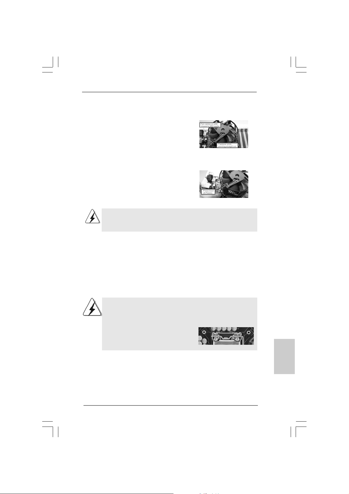
Etape 2. Placez le dissipateur thermique sur le socket.
Vérifiez que les câbles du ventilateur sont
orientés vers le côté le plus proche du
connecteur pour ventilateur de processeur
sur la carte mère (CPU_FAN1, voir page 2,
no. 37).
Etape 3. Alignez les attaches avec la carte mère par
les orifices.
Etape 4. Faites tourner les attaches dans le sens des
aiguilles d’une montre, puis, du pouce,
enfoncez les capuchons des attaches pour
les installer et les verrouiller. Répétez
l’opération avec les autres attaches.
Si vous enfoncez les attaches sans les faire tourner dans le sens
des aiguilles d’une montre, le dissipateur thermique ne sera pas fixé
sur la carte mère.
Etape 5. Connectez l’en-tête du ventilateur sur le
connecteur pour ventilateur de processeur
sur la carte mère.
Etape 6. Fixez la longueur de câble en excès avec du
ruban adhésif pour vous assurer que le
câble ne gênera pas le fonctionnement du
ventilateur ou n’entrera pas en contact avec
les autres composants.
(Câbles du ventilateur du côté le plus
proche du connecteur sur la carte mère)
(Orifices des attaches ressortant)
(Enfoncez (4 endroits))
Veuillez noter que cette carte mère prend en charge l’option Combo
Cooler Option (C.C.O.), qui offre un choix flexible pour adopter
deux types différents de refroidisseurs de CPU, les sockets LGA
775 et LGA 1156. Les trous traversant blancs sont pour le
ventilateur de CPU au socket LGA 1156.
ASRock P55 Pro Motherboard
6767
67
6767
çaisçais
çaisçais
çaisçais
çaisçais
çais
çais
FranFran
FranFran
FranFran
FranFran
Fran
Fran
Page 68
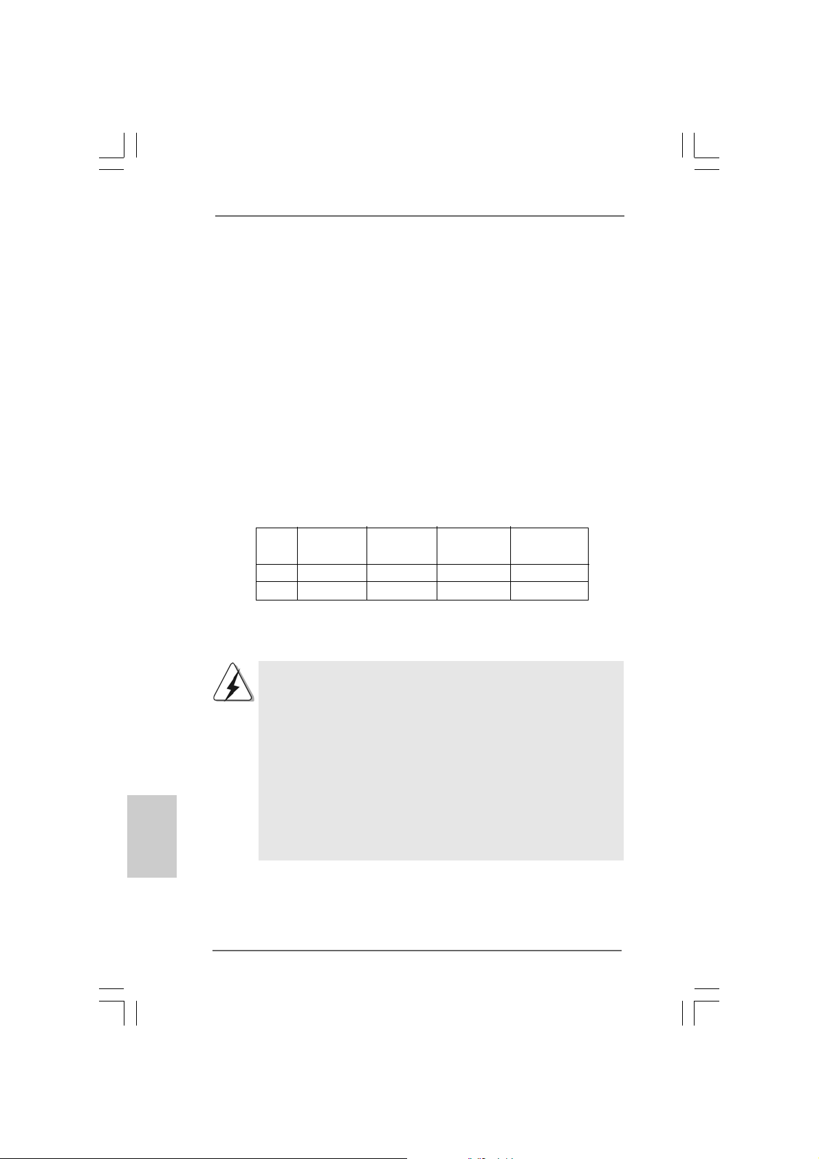
2.3 Installation des modules m émoire [DIMM]2.3 Installation des modules m émoire [DIMM]
2.3 Installation des modules m émoire [DIMM]
2.3 Installation des modules m émoire [DIMM]2.3 Installation des modules m émoire [DIMM]
La carte mère P55 Pro dispose de quatre emplacements DIMM DDR3 (Double Data
Rate 3) de 240-broches, et supporte la Technologie de Mémoire à Canal Double.
Pour effectuer une configuration à canal double, vous devez toujours installer des
paires de DIMM DDR3 identiques (de la même marque, de la même vitesse, de la
même taille et du même type de puce) dans les slots de même couleur. En d’autres
termes, vous devez installer une paire de DIMM DDR3 identiques dans le Canal
Double (DDR3_A1 et DDR3_B1; slots blanc; voir p.2 No. 5), de façon à ce que la
Technologie de Mémoire à Canal Double puisse être activée. Cette carte vous
permet également d’installer quatre modules DIMM DDR3 pour la configuration à
canal double. Cette carte mère vous permet également d’installer quatre modules
DIMM DDR3 pour une configuration double canal; veuillez installer les mêmes
modules DIMM DDR3 dans les quatre emplacements. Vous pouvez vous reporter
au Tableau de configuration mémoire double canal ci-dessous.
Configurations de Mémoire à Canal Double
DDR3_A2 DDR3_A1 DDR3_B2 DDR3_B1
(Slot Bleu) (Slot Blanc) (Slot Bleu) (Slot Blanc)
(1) - Occupé - Occupé
(2)* Occupé Occupé Occupé Occupé
* Pour la configuration (2), veuillez installer des DIMM DDR3 identiques dans les
quatre emplacements.
Français
FrançaisFrançais
FrançaisFrançais
6868
68
6868
1. Si vous voulez installer deux modules de mémoire, pour une
compatibilité et une fiabilité optimales, il est recommandé de les
installer dans des emplacements de la même couleur. En d’autres
termes, installez-les soit dans les emplacements blanc (DDR3_A1 et
DDR3_B1).
2. Si un seul module mémoire ou trois modules mémoire sont installés
dans les slots DIMM DDR3 sur cette carte mère, il sera impossible
d’activer la Technologie de Mémoire à Canal Double.
3. Il n’est pas permis d’installer de la DDR ou DDR2 sur le slot
DDR3; la carte mère et les DIMM pourraient être endommagés.
4. Veuillez tout d’abord installer le module de mémoire dans la fente
blanche (DDR3_B1).
ASRock P55 Pro Motherboard
Page 69
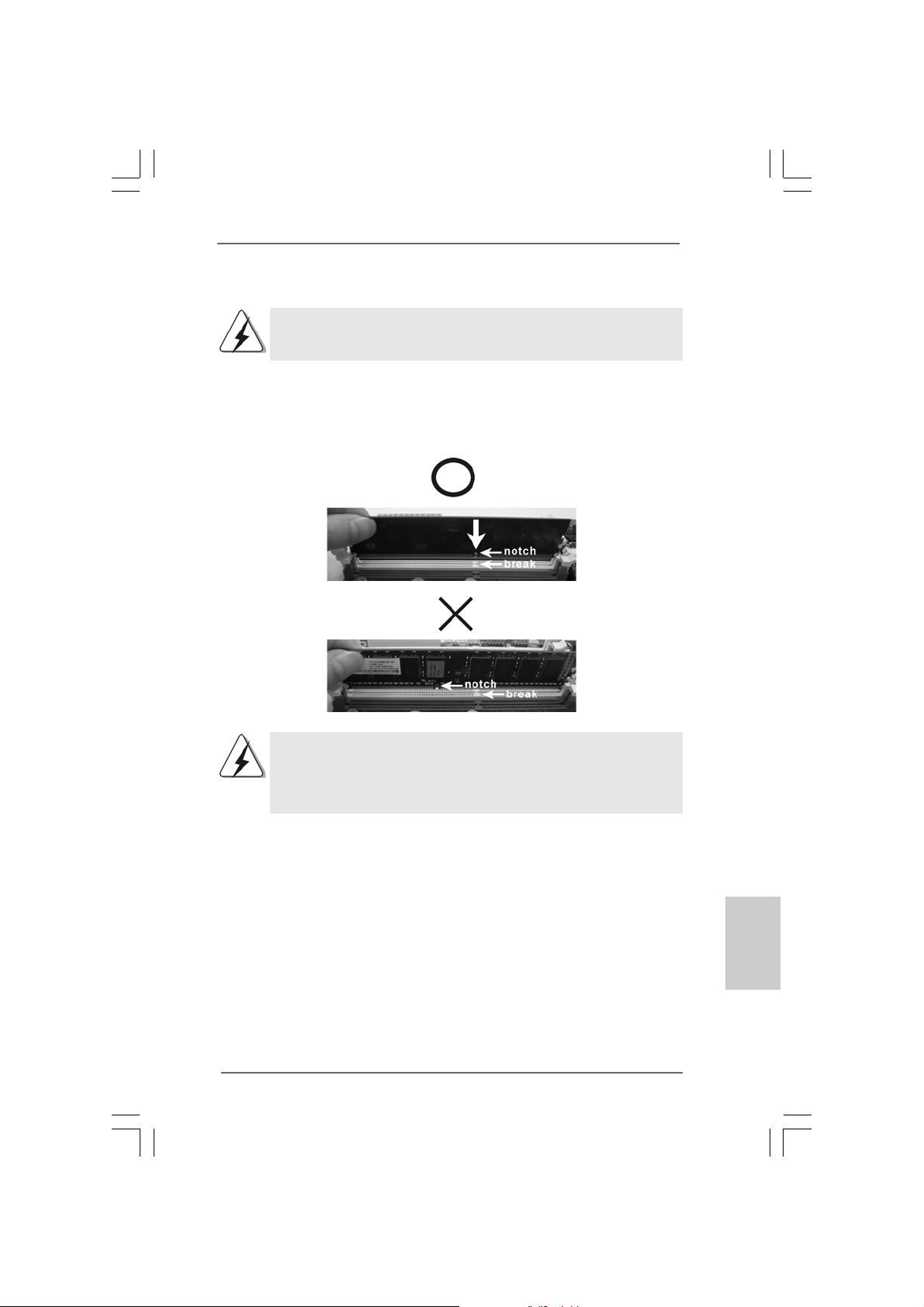
Installation d’un module DIMMInstallation d’un module DIMM
Installation d’un module DIMM
Installation d’un module DIMMInstallation d’un module DIMM
Ayez bien le soin de débrancher l’alimentation avant d’ajouter ou de
retirer des modules DIMM ou les composants du système.
Etape 1. Déverrouillez un connecteur DIMM en poussant les taquets de maintien
vers l’extérieur.
Etap e 2 . Alignez le module DIMM sur son empla ce ment en faisant correspondre les
encoches du module DIMM aux trous du connecteur.
Le module DIMM s’insère uniquement dans un seul sens. Si vous
forcez le module DIMM dans son emplacement avec une mauvaise
orientation cela provoquera des dommages irrémédiables à la
carte mère et au module DIMM.
Etape 3. Insérez fermement le module DIMM dans son emplacement jusqu’à ce que
les clips de maintien situés aux deux extrémités se ferment complètement
et que le module DIMM soit inséré corre ctement.
ASRock P55 Pro Motherboard
6969
69
6969
çaisçais
çaisçais
çais
FranFran
FranFran
Fran
Page 70
2.42.4
Slot d’extension (Slots PCI et Slots PCI Express)Slot d’extension (Slots PCI et Slots PCI Express)
2.4
Slot d’extension (Slots PCI et Slots PCI Express)
2.42.4
Slot d’extension (Slots PCI et Slots PCI Express)Slot d’extension (Slots PCI et Slots PCI Express)
Il y a 2 ports PCI et 4 ports PCI Express sur la carte mère P55 Pro.
Slots PCI: Les slots PCI sont utilisés pour installer des cartes d’extension dotées
d’une interface PCI 32 bits.
Slots PCIE:
Le PCIE1 / PCIE3 (slot PCIE x1; blanc) sert aux cartes PCI Express avec
les cartes de largeur x1 voie, comme la carte Gigabit LAN, la carte
SATA2.
Le PCIE2 (slot PCIE x16; bleu) sert aux cartes graphique s PCI Express de
largeur x16 voies, ou sert à installer des cartes graphiques PCI Express
pour prendre en charge la fonction CrossFireXTM.
Le PCIE4 (slot PCIE x16; orange) sert aux cartes graphiques PCI Express
de largeur x1 voie, comme la carte Gigabit LAN, la carte SATA2, etc., ou
sert à installer des cartes graphiques PCI Express pour prendre en
charge la fonction CrossFireXTM.
1. En mode de carte VGA unique, il est recommandé d’installer une
carte graphique PCI Express x16 dans la fente PCIE2.
2. En mode CrossFireXTM, installez les cartes graphiques PCI Express
x16 dans les fentes PCIE2 et PCIE4. Par conséquent, la fente
PCIE2 fonctionneront avec une largeur de bande x16 tandis que
les fentes PCIE4 fonctionnera avec une largeur de bande x4.
3. Reliez un ventilateur de châssis au connecteur pour ventilateur
de châssis de la carte mère (CHA_FAN1 ou CHA_FAN2) lorsque
vous utilisez plusieurs cartes graphiques afin d’obtenir un
meilleur environnement thermique.
Français
FrançaisFrançais
FrançaisFrançais
7070
70
7070
Installation d’une carte d’extensionInstallation d’une carte d’extension
Installation d’une carte d’extension
Installation d’une carte d’extensionInstallation d’une carte d’extension
Etape 1. Avant d’installer les cartes d’extension, veuillez vous assurer de bien
avoir coupé l’alimentation ou d’avoir débranché le cordon d’ali mentation.
Veuillez lire la documentation des cartes d’extension et effe ctuer le s
réglages matériels nécessaires pour les cartes ava nt de débuter
l’installation.
Etape 2. Retirez l’équerre correspondant au connecteur que vous voulez utiliser .
Gardez la vis pour un usage ultérieur.
Etape 3. Alignez la carte sur le connecteur et appuyez fermement jusqu’à l’insertion
complète de la carte dans son emplacement.
Etape 4. Fixez la carte sur le châssis à l’aide d’une vis.
ASRock P55 Pro Motherboard
Page 71

TMTM
TM
2.52.5
Mode d’emploi pour CrossFireXMode d’emploi pour CrossFireX
2.5
Mode d’emploi pour CrossFireX
2.52.5
Mode d’emploi pour CrossFireXMode d’emploi pour CrossFireX
TMTM
TM
CrossFireXCrossFireX
CrossFireX
CrossFireXCrossFireX
Cette carte mère prend en charge CrossFireXTM et Quad CrossFireXTM. La
technologie CrossFireXTM offre le moyen le plus avantageux de combiner divers
dispositifs de traitement graphique performants (GPU) dans un seul PC. Combinez
une gamme de modes d’exploitation différents avec des logiciels intelligents et des
mécanismes d’interconnexion innovants. CrossFireXTM permet d’obtenir le niveau
de performance le plus haut possible et une haute qualité d’image pour les
applications 3D. En général, CrossFireXTM est pris en charge par Windows® XP
avec le Pack de service 2 et VistaTM. Quad CrossFireXTM est pris en charge par
Windows® VistaTM uniquement. Veuillez consulter le site d’AMD pour les mises à
jour de driver ATITM CrossFireXTM. Veuillez suivre les instructions d’installation de la
page 16 pour plus de détails.
2.6 “Surround Display”2.6 “Surround Display”
2.6 “Surround Display”
2.6 “Surround Display”2.6 “Surround Display”
Cette carte mère supporte la mise à niveau de Surround Display. Avec la carte
externe d’extension VGA PCI Express, vous pouvez facilement jouir des
avantages de la caractéristique de l’affichage Surround. Pour les instructions
détaillées, veuillez vous reporter au document qui se trouve sur le chemin suivant
dans le CD d’assistance : ..\ Surround Display Information
TMTM
TMTM
et Quad et Quad
et Quad
et Quad et Quad
ASRock P55 Pro Motherboard
7171
71
7171
çaisçais
çaisçais
çais
FranFran
FranFran
Fran
Page 72
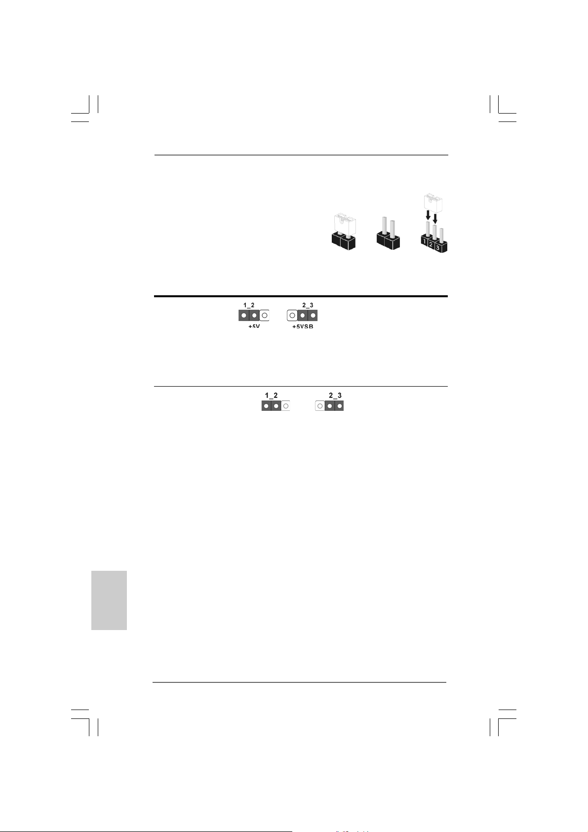
Français
FrançaisFrançais
FrançaisFrançais
2.7 Réglage des cavaliers2.7 Réglage des cavaliers
2.7 Réglage des cavaliers
2.7 Réglage des cavaliers2.7 Réglage des cavaliers
L’illustration explique le réglage des cavaliers.
Quand un capuchon est placé sur les broches,
le cavalier est « FERME ». Si aucun capuchon
ne relie les broches,le cavalier est « OUVERT ».
L’illustration montre un cavalier à 3 broches dont
les broches 1 et 2 sont “FERMEES” quand le
capuchon est placé sur ces 2 broches.
Le cavalier Description
PS2_USB_PWR1 Court-circuitez les broches 2
(voir p.2 No. 1) et 3 pour choisir +5VSB
Note: Pour sélectionner +5VSB, il faut obligatoirement 2 Amp et un courant
standby supérieur fourni par l’alimentation.
Effacer la CMOS
(CLRCMOS1,
le cavalier à 3 broches)
(voir p.2 No. 15)
Note: CLRCMOS1 vous permet d’effa cer les données qui se trouvent da ns la CMOS.
Les données dans la CMOS comprennent les inf ormations de conf iguration du
système telles que le mot de passe système, la date, l’heure et le s paramètres
de configuration du système. Pour effa cer et réinitialiser le s paramètres du
système pour retrouver la configuration par défaut, veuillez mettre l’ordinateur
hors tension et débrancher le cordon d’alimentation de l’ali mentation éle ctrique.
Attendez 15 secondes, puis utilisez un ca puchon de cavalier pour courtcircuiter la broche 2 et la broche 3 sur CLRCMOS1 pendant 5 secondes. Après
avoir court-circuité le cavalier Effacer la CMOS, veuillez enlever le capuchon de
cavalier. Toutefois, veuillez ne pas effa cer la CMOS tout de suite après avoir mis
le BIOS à jour. Si vous avez besoin d’eff a cer la CMOS lors que vous avez fini de
mettre le BIOS à jour, vous devez d’abord initialiser le système, puis le mettre
hors tension avant de procéder à l’opération d’effa ce ment de la CMOS.
Paramètres
par défaut
Ferme Ouvert
(standby) et permettre aux
périphériques PS/2 ou USB de
réveiller le système.
Effacer la
CMOS
7272
72
7272
ASRock P55 Pro Motherboard
Page 73
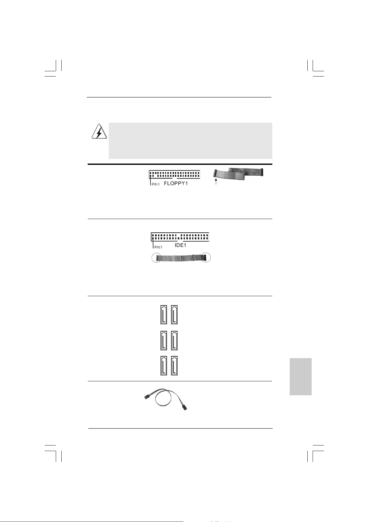
2.8 En-têtes et Connecteurs sur Carte2.8 En-têtes et Connecteurs sur Carte
2.8 En-têtes et Connecteurs sur Carte
2.8 En-têtes et Connecteurs sur Carte2.8 En-têtes et Connecteurs sur Carte
Les en-têtes et connecteurs sur carte NE SONT PAS des cavaliers.
NE PAS placer les capuchons de cavalier sur ces en-têtes et
connecteurs. Le fait de placer les capuchons de cavalier sur les entêtes et connecteurs causera à la carte mère des dommages
irréversibles!
Connecteur du lecteur
de disquette
(FLOPPY1 br. 33)
(voir p.2 No. 27)
le côté avec fil rouge côté
Broche1
Note: Assurez-vous que le côté avec fil rouge du câble est bien branché sur le
côté Broche1 du connecteur.
Connecteur IDE primaire (bleu)
(IDE1 br. 39, voir p.2 No. 14)
connecteur bleu connecteur noir
vers la carte mère vers le disque dur
Câble ATA 66/100/133 80 conducteurs
Note: V euillez vous reporter aux instructions du fa brica nt de votre IDE périphérique
pour les détails.
Connecteurs Série A T AII Ces six connecteurs Série
(SATAII_1_2: AT AII (SA T AII) prennent en
voir p.2 No. 9) charge les câbles SATA pour
(SAT AII_3_4: les périphériques de stockage
voir p.2 No. 10) internes. L’interface SATAII
(SATAII_5_6: actuelle permet des taux
voir p.2 No. 1 1) transferts de données pouvant
aller jusqu’à 3,0 Gb/s.
SAT AII_5_6 SA T AII_3_4 SA T AII_1_2
Câble de données T oute cote du cable de data SA T A
Série AT A (SATA) peut etre connecte au disque dur
(en option) SATA / SAT AII ou au connecteur
SATAII sur la carte mere.
ASRock P55 Pro Motherboard
7373
73
7373
çaisçais
çaisçais
çais
FranFran
FranFran
Fran
Page 74
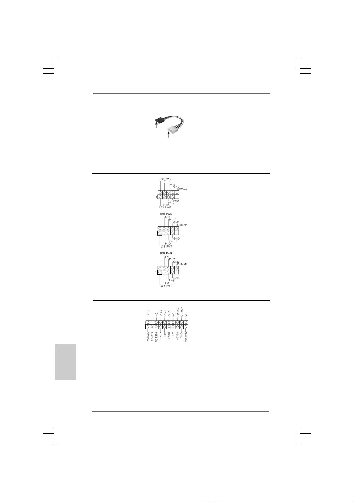
Cordon d’alimentation Veuillez connecter l’extrémité
Série ATA (SA TA) noire du cordon d’alimentation
(en option) SATA sur le conne cteur
connecter au
connecteur
d’alimentation du
disque
dur SATA
connecter à
l’unité
d’alimentation
électrique
d’alimentation sur chaque unité.
Connectez ensuite l’extrémité
blanche du cordon d’alimentation
SATA sur le connecteur
d’alimentation de l’unité
d’alimentation électrique.
En-tête USB 2.0 A côté des six ports
(US12_13 br.9) USB 2.0 par défaut sur le
(voir p.2 No. 23) panneau E/S, il y a trois
embases USB 2.0 sur cette
carte mère. Chaque embase
USB 2.0 peut prendre en
(US10_11 br .9) charge 2 ports USB 2.0.
(voir p.2 No. 24)
(US8_9 br.9)
(voir p.2 No. 25)
Français
FrançaisFrançais
FrançaisFrançais
7474
74
7474
Connecteur TPM
(TPM1 br. 19)
(voir p.2 No. 19)
Ce connecteur prend en charge
un système Trusted Platform
Module (TPM ou module de
plateforme de confiance), qui
peut stocker des clés de
sécurité, des certificats
numériques, des mots de passe
et des données. Un système
TPM permet également de
renforcer la sécurité des
réseaux, protège les identités
numériques, et assure l’intégrité
de la plate-forme.
ASRock P55 Pro Motherboard
Page 75
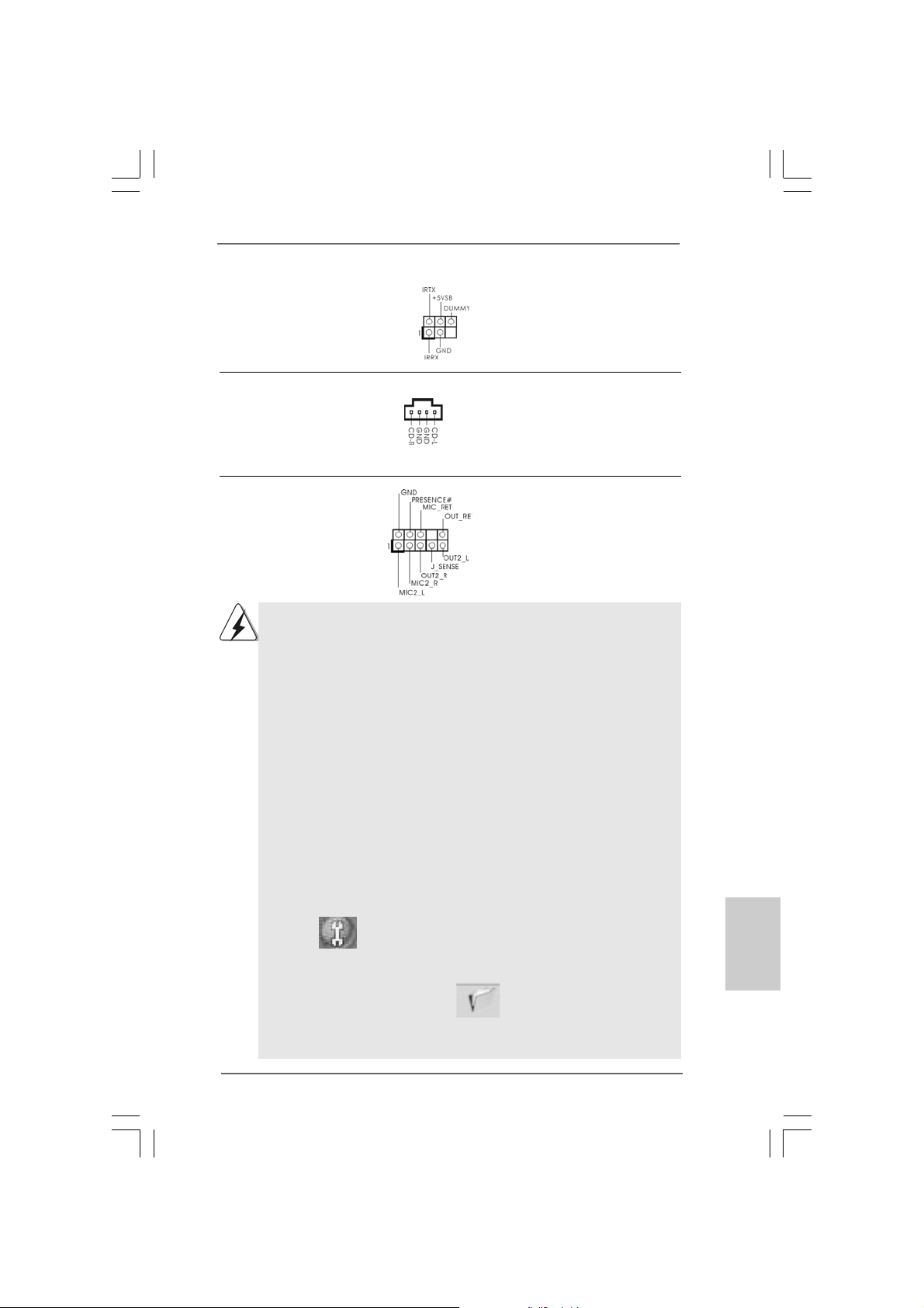
prend en charge
sted Platform
. Un système
assure l’intégrité
En-tête du module infrarouge Cet en-tête supporte un module
(IR1 br.5) infrarouge optionnel de
(voir p.2 No. 21) transfert et de réception sans
fil.
Connecteurs audio internes Ils vous permettent de gérer des
(CD1 br. 4) entrées audio à partir de sources
(CD1: voir p.2 No. 31) stéréo comme un CD-ROM,
CD1
DVD-ROM, un tuner TV ou une
carte MPEG.
Connecteur audio panneau C’est une interface pour un câble
av ant audio en façade qui permet le
(HD_AUDIO1 br. 9) branchement et le contrôle
(voir p.2 No. 30) commodes de périphériques
audio.
1. L’audio à haute définition (HDA) prend en charge la détection de fiche,
mais le fil de panneau sur le châssis doit prendre en charge le HDA pour
fonctionner correctement. Veuillez suivre les instructions dans notre
manuel et le manuel de châssis afin installer votre système.
2. Si vous utilisez le panneau audio AC’97, installez-le sur l’adaptateur audio
du panneau avant conformément à la procédure ci-dessous :
A. Connectez Mic_IN (MIC) à MIC2_L.
B. Connectez Audio_R (RIN) à OUT2_R et Audio_L (LIN) à OUT2_L.
C. Connectez Ground (GND) à Ground (GND).
D. MIC_RET et OUT_RET sont réservés au panneau audio HD. Vous
n’avez pas besoin de les connecter pour le panneau audio AC’97.
E. Entrer dans l’utilitaire de configuration du BIOS. Saisir les Paramètres
avancés puis sélectionner Configuration du jeu de puces. Définir
l’option panneau de commande de [Auto] à [Activé].
F. Entrer dans le système Windows. Cliquer sur l’icône sur la barre de
tâches dans le coin inférieur droite pour entrer dans le Gestionnaire
audio Realtek HD.
Pour Windows® XP / XP 64-bit OS:
Cliquer sur « E/S audio», sélectionner « Paramètres du connecteur »
, choisir « Désactiver la détection de la prise du panneau de
commande » et sauvegarder les changements en cliquant sur « OK ».
Pour Windows
Cliquer droit “Fichier” icone , selectionner” la detection
incapable de jack de panel d’avant “ et sauvegarder le changement par
cliquer”ok”.
®
VistaTM / VistaTM 64-bit OS:
çaisçais
çaisçais
çais
FranFran
FranFran
Fran
ASRock P55 Pro Motherboard
7575
75
7575
Page 76
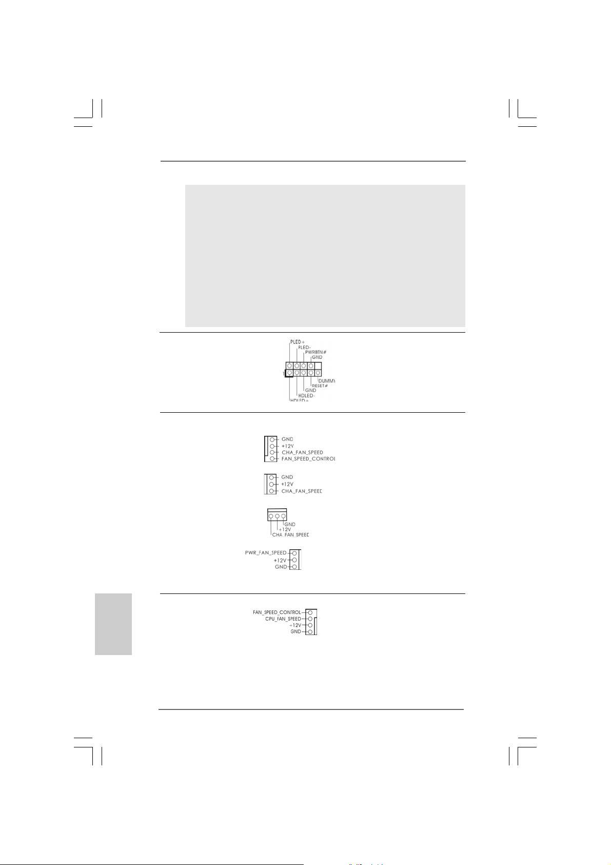
G. Pour activer le mic.
Pour les SE Windows® XP / XP 64 bits :
Veuillez sélectionner “Front Mic” ( Mic. Avant) comme le dispositif
d’enregistrement par défaut.
Si vous voulez entendre votre voix à travers le mic. avant veuillez
désactiver l’icône «Silence» dans “Front Mic” ( Mic. Avant) de la portion
“Playback” (Lecture).
Pour les SE Windows® VistaTM / VistaTM 64 bits :
Allez à l’onglet «Front Mic» ( Mic. Avant) dans le panneau de
commandes Realtek.
Cliquez sur «Configurer le dispositif par défaut» pour faire du Mic Avant
le dispositif d’enregistrement par défaut.
En-tête du panneau système Cet en-tête permet d’utiliser
(PANEL1 br.9) plusieurs fonctions du
(voir p.2 No. 22) panneau système frontal.
Français
FrançaisFrançais
FrançaisFrançais
7676
76
7676
Connecteur pour châssis et ventilateur
(CHA_FAN1 br. 4)
(voir p.2 No. 7)
Branchez les câbles du
ventilateur aux connecteurs pour
ventilateur et faites correspondre
le fil noir à la broche de terre.
(CHA_FAN2 br. 3)
(voir p.2 No. 8)
(CHA_FAN3 br. 3)
(voir p.2 No. 12)
(PWR_FAN1 br. 3)
(voir p.2 No. 38)
Connecteur du ventilateur Veuillez connecter le câble de
de l’UC ventilateur d’UC sur ce
(CPU_FAN1 br. 4) connecteur et brancher le fil
(voir p.2 No. 37) noir sur la broche de terre.
4
3
2
1
ASRock P55 Pro Motherboard
Page 77
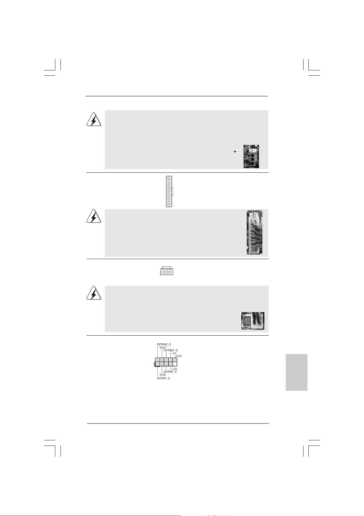
ien que cette carte mère offre un support de (Ventilateur silencieux)
ventilateur de CPU à 4 broches , le ventilateur de CPU à 3 broches peut bien
fonctionner même sans la fonction de commande de vitesse du ventilateur.
Si vous prévoyez de connecter le ventilateur de CPU à 3 broches au
connecteur du ventilateur de CPU sur cette carte mère, veuillez le connecter
aux broches 1-3.
Installation de ventilateur à 3 broches
Broches 1-3 connectées
onnecteurs pour
es correspondre
En-tête d’alimentation ATX Veuillez connecter l’unité
(ATXPWR1 br. 24) d’alimentation A TX sur cet en-
(voir p.2 No. 6) tête.
Bien que cette carte mère fournisse un connecteur de
courant ATX 24 broches, elle peut encore fonctionner si vous
adopter une alimentation traditionnelle ATX 20 broches. Pour
utiliser une alimentation ATX 20 broches, branchez à
l’alimentation électrique ainsi qu’aux broches 1 et 13.
Connecteur ATX 12V Veuillez connecter une unité
(ATX12V1 br .8) d’alimentation électrique ATX
(voir p.2 No. 2) 12V sur ce connecteur.
Bien que cette carte mère possède 8 broches connecteur d’alimentation
ATX 12V, il peut toujours travailler si vous adoptez une approche
traditionnelle à 4 broches ATX 12V alimentation. Pour utiliser
l’alimentation des 4 broches ATX, branchez votre alimentation
avec la broche 1 et la broche 5.
12 124
13
20-Installation de l’alimentation électrique A TX
8 5
4 1
4-Installation d’alimentation à 4 broches A TX 12V
12
1
8 5
4 1
Header de IEEE 1394 Sauf un port de default IEEE
(FRONT_1394 br. 9) 1394 sur le panel I/O, il y a un
(voir p.2 No. 26) header de IEEE1394
(FRONT_1394) sur cette carte
mere. Le header de IEEE 1394
peut supporter un port de IEEE
1394.
24
13
çaisçais
çaisçais
çais
FranFran
FranFran
Fran
ASRock P55 Pro Motherboard
7777
77
7777
Page 78
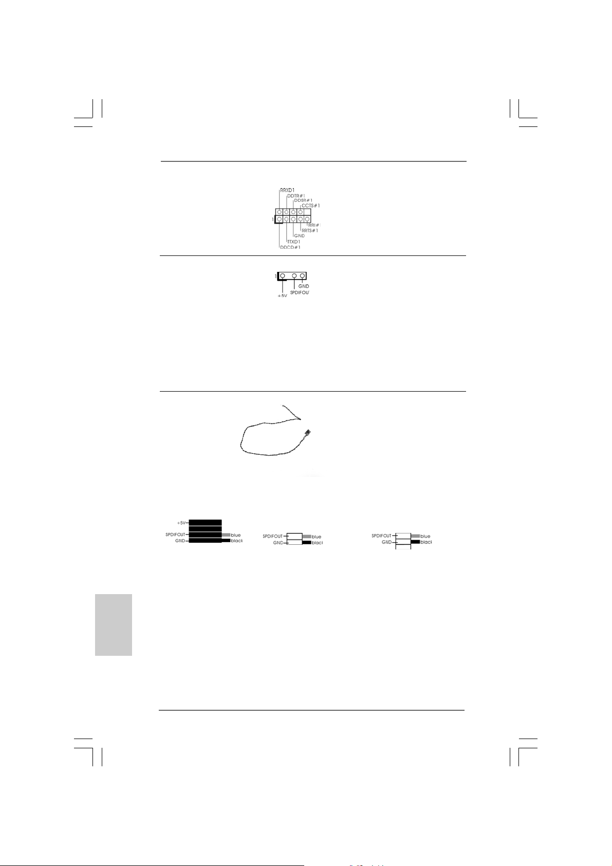
En-tête de port COM Cette en-tête de port COM est
(COM1 br.9) utilisée pour prendre en charge
(voir p.2 No. 28) un module de port COM.
Connecteur HDMI_SPDIF Connecteur HDMI_SPDIF,
(HDMI_SPDIF1 3-pin) fournissa nt une sortie audio
(voir p.2 No. 29) SPDIF vers la carte V GA HDMI,
et permettant au système de
se connecter au un téléviseur
numérique HDMI /un projecteur
/ un périphérique LCD. Veuillez
brancher le connecteur
HDMI_SPDIF de la carte V GA
HDMI sur ce connecteur.
Français
FrançaisFrançais
FrançaisFrançais
Câble HDMI_SPDIF Veuillez connecter l’extrémité
(en option) noire (A) du câble HDMI_SPDIF
C
B
A
au collecteur HDMI_SPDIF de la
carte-mère. Connectez ensuite
l’extrémité blanche (B ou C) du
câble HDMI_SPDIF au
connecteur HDMI_SPDIF de la
carte VGA HDMI.
A. extrémité noire B. extrémité blanche C. extrémité blanche
(2 briches) (3 briches)
7878
78
7878
ASRock P55 Pro Motherboard
Page 79
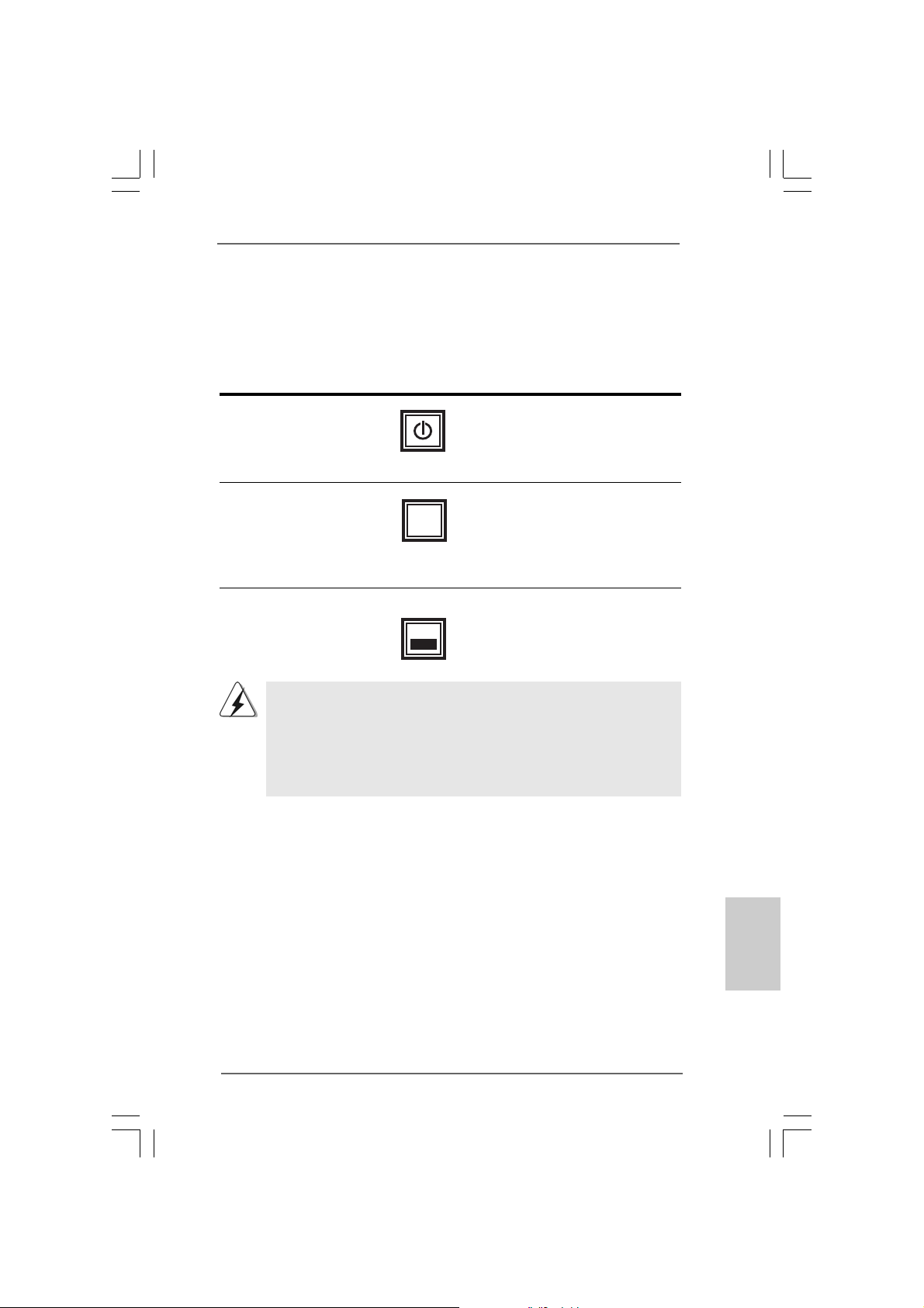
2.9 Interrupteur rapides2.9 Interrupteur rapides
2.9 Interrupteur rapides
2.9 Interrupteur rapides2.9 Interrupteur rapides
Cette carte mère dispose de trois interrupteurs rapides : un interrupteur
d’alimentation, un interrupteur de réinitialisation et un interrupteur d’effacement de
CMOS, permettant aux utilisateurs de rapidement allumer/éteindre ou réinitialiser le
système, ainsi que d’effacer les valeurs du CMOS.
Interrupteur d’alimentation
(PWRBTN)
(voir p.2 No. 20)
Interrupteur de réinitialisation
(RSTBTN)
(voir p.2 No. 18)
Interrupteur d’effacement de CMOS
(CLRCBTN)
(voir p.2 No. 17)
Vous n’êtes pas autorisé à utiliser la fonction de l’interrupteur Clear CMOS
(Effacement du CMOS) si vous configurez un mot de passe pour le
système. Si vous voulez effacer les valeurs du CMOS, veuillez d’abord
effacer le mot de passe de votre système ou vous référer plutôt à la
description “Clear CMOS jumper (Cavalier d’effacement du CMOS)” de la
page 72.
RESET
clr
CMOS
L’interrupteur d’alimentation est
un interrupteur rapide, qui permet
à l’utilisateur d’allumer/éteindre
rapidement le système.
L’interrupteur de réinitialisation
est un interrupteur rapide, qui
permet à l’utilisateur de
réinitialiser ra pide ment le
système.
L’interrupteur d’effacement de
CMOS est un interrupteur rapide
qui permet à l’utilisateur d’effacer
rapidement les valeurs du CMOS.
ASRock P55 Pro Motherboard
7979
79
7979
çaisçais
çaisçais
çais
FranFran
FranFran
Fran
Page 80

2.102.10
LED de débogageLED de débogage
2.10
LED de débogage
2.102.10
LED de débogageLED de débogage
La LED de débogage intégrée sert à fournir des informations de code, ce qui rend
le dépannage encore plus facile. Veuillez consulter les diagrammes des pages 27,
28 et 29 pour la lecture des codes LED de débogage.
2.112.11
Guide d’installation des pilotesGuide d’installation des pilotes
2.11
Guide d’installation des pilotes
2.112.11
Guide d’installation des pilotesGuide d’installation des pilotes
Pour installer les pilotes sur votre système, veuillez d’abord insérer le CD dans votre
lecteur optique. Puis, les pilotes compatibles avec votre système peuvent être
détectés automatiquement et sont listés sur la page du pilote du CD. V euillez suivre
l’ordre de haut en bas sur le côté pour installer le s pilote s requis. En conséquence,
les pilotes que vous installez peuvent fonctionner correctement.
Français
FrançaisFrançais
FrançaisFrançais
2.12 Installation de Windows2.12 Installation de Windows
2.12 Installation de Windows
2.12 Installation de Windows2.12 Installation de Windows
TMTM
TM
Vista Vista
Vista
Vista Vista
Si vous souhaitez installer Windows® XP / XP 64-bit / VistaTM / VistaTM 64-bit OS
sur votre lecteur de disque dur SATA / SATAII avec les fonctions RAID, veuillez
vous référer au document de l’étape suivante sur le CD de support pour connaître
la procédure détaillée:
..\ RAID Installation Guide (Guide d’installation RAID)
2.132.13
Installation de Windows Installation de Windows
2.13
Installation de Windows
2.132.13
Installation de Windows Installation de Windows
Vista Vista
Vista
Vista Vista
Si vous voulez installer Windows® XP / XP 64-bit / VistaTM / VistaTM 64-bits sur vos
disques durs SATA / SAT AII sa n s les f onctions RAID, veuillez suivre le s procédures cidessous, en fonction de l’OS que vous installez.
2.13.1 Installation de Windows2.13.1 Installation de Windows
2.13.1 Installation de Windows
2.13.1 Installation de Windows2.13.1 Installation de Windows
fonctions RAID fonctions RAID
fonctions RAID
fonctions RAID fonctions RAID
Si vous voulez installer Windows® XP / XP 64-bit sur vos disques durs SATA /
SATAII sans les fonctions RAID, veuillez suivre la procédure ci-dessous.
Utilisation des disques durs SATA / SATAII sans NCQ fonctions
ETAPE 1 : Configurez le BIOS.
A. Accédez à BIOS SETUP UTILITY (Utilitaire de configuration BIOS) écran
Avancé Configuration Storage.
B. Réglez «SATAII Operation Mode « sur [IDE].
ETAPE 2 : Installez le système d’exploitation Windows® XP / XP 64 bits
sur votre système.
TMTM
64-bit avec fonctions RAID 64-bit avec fonctions RAID
64-bit avec fonctions RAID
64-bit avec fonctions RAID 64-bit avec fonctions RAID
TMTM
TM
TMTM
64-bit sans fonctions RAID 64-bit sans fonctions RAID
64-bit sans fonctions RAID
64-bit sans fonctions RAID 64-bit sans fonctions RAID
®
XP / XP 64-bit / Vista XP / XP 64-bit / Vista
XP / XP 64-bit / Vista
XP / XP 64-bit / Vista XP / XP 64-bit / Vista
®®
®
®®
XP / XP 64-bit / Vista XP / XP 64-bit / Vista
XP / XP 64-bit / Vista
XP / XP 64-bit / Vista XP / XP 64-bit / Vista
®
XP / XP 64-bit sans XP / XP 64-bit sans
XP / XP 64-bit sans
XP / XP 64-bit sans XP / XP 64-bit sans
TMTM
TM
TMTM
TMTM
TM
TMTM
/ /
/
/ /
/ /
/
/ /
8080
80
8080
ASRock P55 Pro Motherboard
Page 81

TMTM
TM
Vista Vista
Vista
Vista Vista
TMTM
/ Vista / Vista
/ Vista
/ Vista / Vista
2.13.2 Installation de Windows2.13.2 Installation de Windows
2.13.2 Installation de Windows
2.13.2 Installation de Windows2.13.2 Installation de Windows
sans fonctions RAID sans fonctions RAID
sans fonctions RAID
sans fonctions RAID sans fonctions RAID
Si vous voulez installer Windows® VistaTM / VistaTM 64-bit sur vos disques durs
SATA / SATAII sans les fonctions RAID, veuillez suivre la procédure ci-dessous.
Utilisation des disques durs SAT A / SATAII sa n s NCQ fonction s
ETAPE 1 : Configurez le BIOS.
A. Accédez à BIOS SETUP UTILITY (Utilitaire de configuration BIOS) écran
Avancé Configuration Storage.
B. Réglez «SATAII Operation Mode « sur [IDE].
ETAPE 2: Installer le système d’exploitation Windows® VistaTM /
Vista
Utilisation des disques durs SATA / SATAII avec NCQ fonctions
ETAPE 1 : Configurez le BIOS.
A. Accédez à BIOS SETUP UTILITY (Utilitaire de configuration BIOS) écran
Avancé Configuration Storage.
B. Réglez «SATAII Operation Mode « sur [AHCI].
ETAPE 2: Installer le système d’exploitation Windows® VistaTM /
Vista
Insérez le disque optique de Windows® VistaTM / VistaTM 64-bits dans le lecteur
optique pour démarrer votre système, et suivez les instructions pour installer l’OS
Windows® VistaTM / VistaTM 64-bits sur votre système. Lorsque vous voyez la page
“Où souhaitez-vous installer Windows ?”, veuillez insérer le CD Support d’ ASRock
dans votre lecteur optique, et cliquer sur le bouton “Charger le pilote” en bas à gauche
pour charger les pilotes AHCI Intel®. Les pilotes AHCI Intel® sont sous le chemin
suivant du CD Support:
.. \ I386 (Pour les utilisateurs de Windows® VistaTM)
.. \ AMD64 (Pour les utilisateurs de Windows® VistaTM 64-bits)
Ensuite, veuillez insérer le disque optique de Windows® VistaTM / VistaTM 64-bits dans
le lecteur optique de nouveau pour continuer l’installation.
TM
64-bit sur votre système.
TM
64-bit sur votre système.
®
TMTM
TM
TMTM
64-bit 64-bit
64-bit
64-bit 64-bit
ASRock P55 Pro Motherboard
8181
81
8181
çaisçais
çaisçais
çais
FranFran
FranFran
Fran
Page 82

3. Informations sur le BIOS
La puce Flash Memory sur la carte mère stocke le Setup du BIOS. Lorsque vous
démarrez l’ordinateur, veuillez presser <F2> pendant le POST (Power-On-SelfTest) pour entrer dans le BIOS; sinon, le POST continue ses tests de routine. Si
vous désirez entrer dans le BIOS après le POST, veuillez redémarrer le système
en pressant <Ctl> + <Alt> + <Suppr>, ou en pressant le bouton de reset sur le
boîtier du système. Vous pouvez également redémarrer en éteignant le système et
en le rallumant. L’utilitaire d’installation du BIOS est conçu pour être convivial. C’est
un programme piloté par menu, qui vous permet de faire défiler par ses divers
sous-menus et de choisir parmi les choix prédéterminés. Pour des informations
détaillées sur le BIOS, veuillez consulter le Guide de l’utilisateur (fichier PDF) dans
le CD technique.
4. Informations sur le CD de support4. Informations sur le CD de support
4. Informations sur le CD de support
4. Informations sur le CD de support4. Informations sur le CD de support
Cette carte mère supporte divers systèmes d’exploitation Microsoft® Windows®:
XP / XP 64 bits / VistaTM / Vista
carte mère contient les pilotes et les utilitaires nécessaires pour améliorer les
fonctions de la carte mère. Pour utiliser le CD technique, insérez-le dans le lecteur
de CD-ROM. Le Menu principal s’affiche automatiquement si “AUTORUN” est activé
dans votre ordinateur. Si le Menu principal n’apparaît pas automatiquement,
localisez dans le CD technique le fichier “ASSETUP.EXE” dans le dossier BIN et
double-cliquez dessus pour afficher les menus.
TM
64 bits / Win7. Le CD technique livré avec cette
Français
FrançaisFrançais
FrançaisFrançais
8282
82
8282
ASRock P55 Pro Motherboard
Page 83
1. Introduzione
Grazie per aver scelto una scheda madre ASRock P55 Pro, una scheda madre
affidabile prodotta secondo i severi criteri di qualità ASRock. Le prestazioni eccellenti
e il design robusto si conformano all’impegno di ASRock nella ricerca della qualità e
della resistenza.
Questa Guida Ra pida all’In stallazione contiene l’introduzione alla motherboard e la guida
passo-passo all’installazione. Informazioni più dettagliate sulla motherboard si possono
trovare nel manuale per l’utente presente nel CD di supporto.
Le specifiche della scheda madre e il software del BIOS possono
essere aggiornati, pertanto il contenuto di questo manuale può subire
variazioni senza preavviso. Nel caso in cui questo manuale sia
modificato, la versione aggiornata sarà disponibile sul sito di ASRock
senza altro avviso. Sul sito ASRock si possono anche trovare le più
recenti schede VGA e gli elenchi di CPU supportate.
ASRock website http://www.asrock.com
Se si necessita dell’assistenza tecnica per questa scheda madre,
visitare il nostro sito per informazioni specifiche sul modello che si
sta usando.
www.asrock.com/support/index.asp
1.1 Contenuto della confezione1.1 Contenuto della confezione
1.1 Contenuto della confezione
1.1 Contenuto della confezione1.1 Contenuto della confezione
Scheda madre ASRock P55 Pro
(ATX Form Factor: 12.0-in x 8.6-in, 30.5 cm x 21.8 cm)
Guida di installazione rapida ASRock P55 Pro
CD di supporto ASRock P55 Pro
Un cavo IDE 80-pin Ultra A T A 66/100/133
Un cavo per floppy drive a 1,44 Mb
Quattro cavi dati Serial ATA (SATA) (opzionali)
Un cavi di alimentazione HDD Serial ATA (SATA) (opzionali)
Un I/O Shield
ASRock P55 Pro Motherboard
8383
83
8383
ItalianoItaliano
ItalianoItaliano
Italiano
Page 84
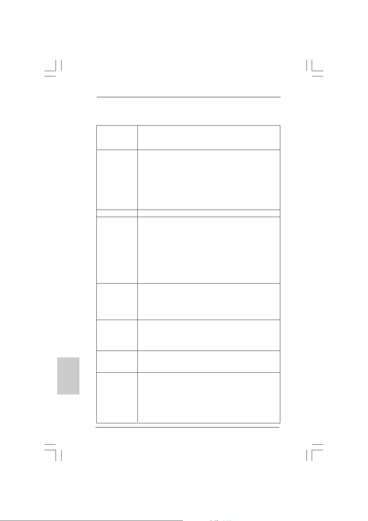
Italiano
ItalianoItaliano
ItalianoItaliano
8484
84
8484
1.21.2
SpecificheSpecifiche
1.2
Specifiche
1.21.2
SpecificheSpecifiche
Piattaforma - ATX Form Factor: 12.0-in x 8.6-in, 30.5 cm x 21.8 cm
- Design condensatore compatto (conden satori a conduttore in
polimero di alta qualità realizzati al 100% in Giappone)
Processore - Supporto dei processori Intel® CoreTM i7 ed Intel® CoreTM i5
nel pacchetto LGA1156
- Struttura di fase con alimentazione V8 + 2 avanzata
- Supporto della tecnologia Intel® Turbo Boost
- Supporto tecnologia Hyper Threading (vedi ATTENZIONE 1)
- Supporta la tecnologia overclocking “slegata”
(vedi ATTENZIONE 2)
- Supporto CPU EM64T
Chipset - Intel® P55
Memoria - Supporto tecnologia Dual Channel Memory
(vedi ATTENZIONE 3)
- 4 x slot DDR3 DIMM
- Supporto DDR3 2600+(OC)/2133(OC)/1866(OC)/1600/1333/
1066 non-ECC, momoria senza buffer
- Capacità massima della memoria di sistema: 16GB
(vedi ATTENZIONE 4)
- Supporto di Intel® XMP (Extreme Memory Profile)
(vedi ATTENZIONE 5)
Slot di - 1 x Alloggio PCI Express 2.0 x16 (a modalità x16)
espansione - 1 x Alloggio PCI Express 2.0 x16 (a modalità x4, 2,5GT/s)
- 2 x Alloggi PCI Express 2.0 x1 (2,5GT/s)
- 2 x Alloggi PCI
- Supporto di ATITM CrossFireXTM e Quad CrossFireX
Audio - 7.1 CH Windows® VistaTM Premium Level HD Audio con protezioni
contenuti
- DAC con raggio dinamico di 110dB (ALC890 Audio Codec)
- Supporto audio Blu-ray Premium
LAN - PCIE x1 Gigabit LAN 10/100/1000 Mb/s
- Realtek RTL81 1 1DL
- Supporta Wake-On-LAN
Pannello I/O Panel
posteriore I/O - 1 x porta PS/2 per mouse
- 1 x porta PS/2 per tastiera
- 1 x Porta coassi ale SPDIF Out
- 1 x Porta ottica SPDIF Out
- 6 x porte USB 2.0 già integrate
- 2 x Connettore alimentato eSATAII/USB
ASRock P55 Pro Motherboard
TM
Page 85
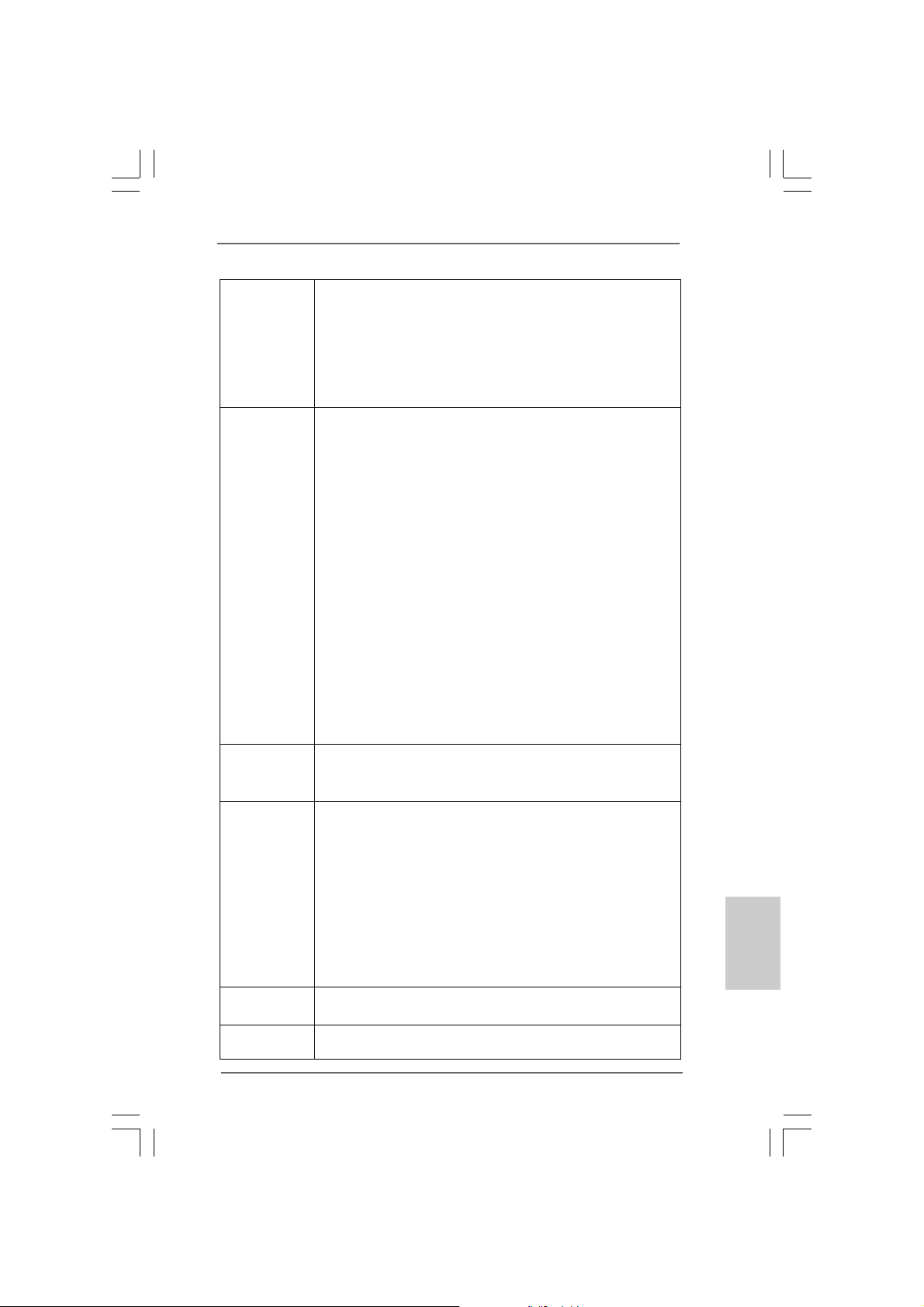
- 1 x porte LAN RJ-45 con LED (LED azione/collega mento e LED
velocità)
- 1 x porte IEEE 1394
- 1 x interruttore di pulizia CMOS con LED
- Connettore HD Audio: cassa laterale / cassa posteriore / cassa
centrale / bassi / ingresso line a / cassa frontale / microfono
(vedi ATTENZIONE 6)
Connettori - 6 x connettori SAT AII 3.0Go/s, sopporta RAID (RAID 0, RAID 1,
RAID 10, RAID 5 ed Intel M atrix Storage), NCQ, AHCI e
“Collegamento a caldo” (vedi ATTENZIONE 7)
- 1 x connettori ATA133 IDE (supporta fino a 2 dispositivi IDE)
- 1 x porta Floppy
- 1 x Collettore modulo infrarossi
- 1 x collettore porta COM
- 1 x connettore HDMI_SPDIF
- 1 x collettore IEEE 1394
- 1 x collettore TPM
- Connettore CPU/Chassis/Alimentazione ventola
- 24-pin collettore alimentazione A TX
- 8-pin connettore A TX 12V
- Connettori audio interni
- Connettore audio sul pannello frontale
- 3 x Collettore USB 2.0 (supporta 6 porte USB 2.0)
(vedi ATTENZIONE 8)
- 1 x Dr. Debug (LED debug con 7 segmenti)
Interruttore - 1 x interruttore pulizia CMOS con LED
rapido - 1 x interruttore di alimentazione con LED
- 1 x interruttore di reset con LED
BIOS - 16Mb AMI BIOS
- Suppor AMI legal BIOS
- Supporta “Plug and Play”
- Compatibile con ACPI 1.1 wake up events
- Supporta jumperfree
- Supporta SMBIOS 2.3.1
- Regolazione multi-voltaggio CPU, VCCM, SB, VTT, VCCM REF,
PCH_PLL
- Supporto I. O. T. (Intelligent Overclocking Technology)
- Smart BIOS supportato
CD di - Driver, utilità, software antivirus (Versione dimostrativa)
supporto
Caratteristica - Sintonizzatore ASRock OC (vedi ATTENZIONE 9)
speciale - Intelligent Energy Saver (Risparmio intelligente dell’energia)
ASRock P55 Pro Motherboard
8585
85
8585
ItalianoItaliano
ItalianoItaliano
Italiano
Page 86
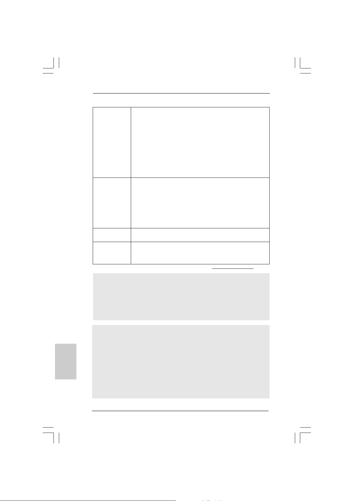
(vedi ATTENZIONE 10)
- Instant Boot
- ASRock Instant Flash (vedi ATTENZIONE 11)
- Booster ibrido:
- Stepless control per frequenza del processore
(vedi ATTENZIONE 12)
- ASRock U-COP (vedi ATTENZIONE 13)
- Boot Failure Guard (B.F.G.)
- Opzione C.C.O. (Combo Cooler Option) (vedi ATTENZIONE 14)
- LED notturno
Monitoraggio - Sensore per la temperatura del processore
Hardware - Sensore temperatura scheda madre
- Indicatore di velocità per la ventola del CPU/Chassis/
Alimentazione
- Ventola CPU silenziosa
- Ventola CPU/chassis con controllo di varie velocità
- Voltaggio: +12V, +5V, +3.3V, Vcore
Compatibi- - Microsoft® Windows® XP / XP 64 bit / VistaTM /
lità SO Vista
TM
64 bit / Win7
Certificazioni - FCC, CE, WHQL
- Predisposto EuP (è necessaria l’alimentazione predisposta per
il sistema EuP) (vedi A TTENZIONE 15)
* Per ulteriori informazioni, prego visitare il nostro sito internet: http://www.asrock.com
AVVISO
Si prega di prendere atto che la procedura di overclocking implica dei rischi, come anche
la regolazione delle impostazioni del BIOS, l’a pplicazione della tecnologia U ntied Overclocking
Technology, oppure l’uso di strumenti di overclocking forniti da terzi. L’overclocking può
influenzare la stabilità del sistema, ed anche provocare danni ai componenti ed alle
periferiche del sistema. La procedura è eseguita a proprio rischio ed a proprie spese. Noi
non possiamo essere ritenuti responsabili per possibili danni provocati dall’overclocking.
Italiano
ItalianoItaliano
ItalianoItaliano
8686
86
8686
ATTENZIONE!
1. Per il settaggio della “Tecnologia Hyper-Threading”, per favore
controllare pagina 55 del Manuale dell’utente all’interno del CD di
supporto.
2. Questa scheda madre supporta la tecnologia overclocking “slegata”.
Per i dettagli leggere “Tecnologia di Untied Overclocking” a pagina 31.
3. Questa scheda madre supporta la tecnologia Dual Channel Memory.
Prima di implementare la tecnologia Dual Channel Memory, assicurarsi di
leggere la guida all’installazione dei moduli di memoria, a pagina 93, per
seguire un’installazione appropriata.
ASRock P55 Pro Motherboard
Page 87
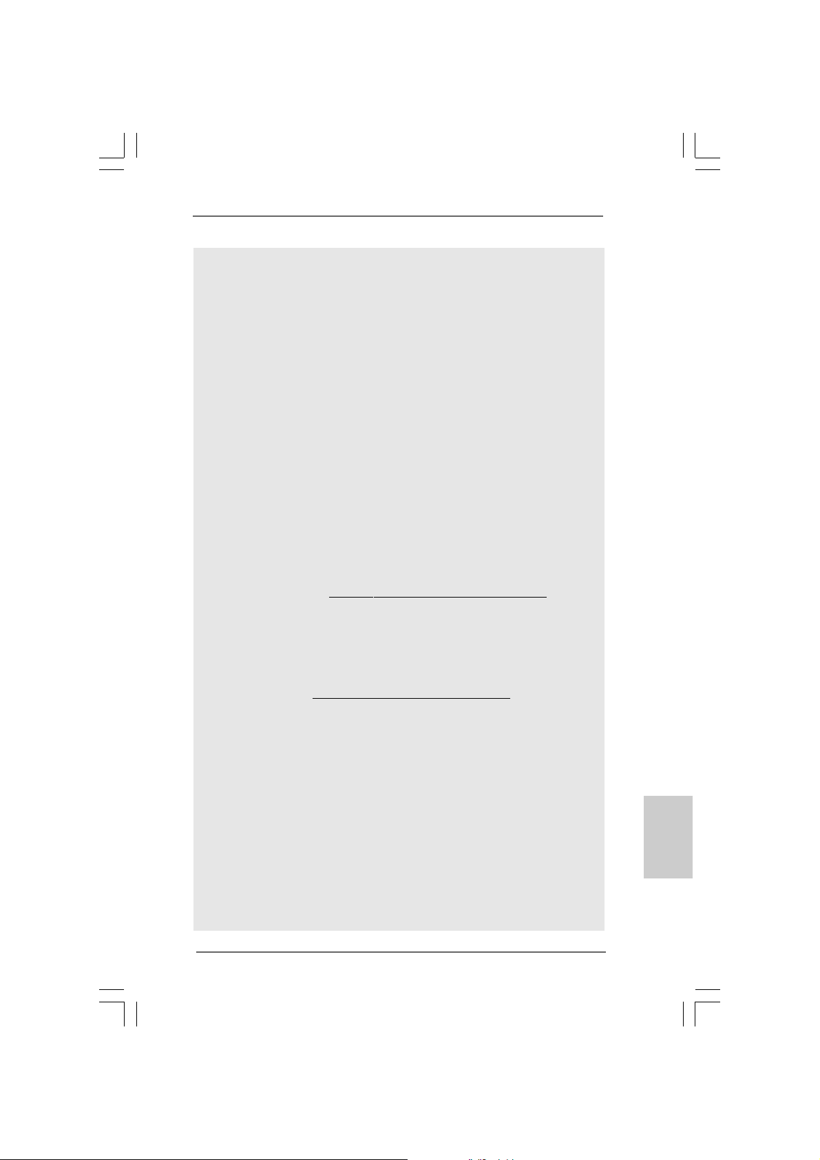
4. A causa delle limitazioni del sistema operativo, le dimensioni effettive
della memoria possono essere inferiori a 4GB per l’accantonamento
riservato all’uso del sistema sotto Windows® XP e Windows® VistaTM. Per
Windows® XP 64-bit e Windows® VistaTM 64-bit con CPU 64-bit, non c’è
tale limitazione.
5. Per quelle CPU che supportano memoria di capacità massima DDR3
1333, XMP DDR3 1600 è supportato tramite overclocking.
6. Questa scheda madre supporta l’ingresso stereo e mono per il
microfono. Questa scheda madre supporta le modalità 2 canali, 4
canali, 6 canali e 8 canali per l’uscita audio. Controllare la tavola a
pagina 3 per eseguire il collegamento appropriato.
7. Prima di installare il disco rigido SATAII con il connettore SATAII, leggere la
“Guida per la configurazione del disco rigido SATAII” a pagina 36 del
“Manuale utente” nel CD in dotazione in modo da poter predisporre il disco
rigido SATAII per la modalità SATAII. È anche possibile connettere il disco
rigido SATA direttamente al connettore SATAII.
8. La Gestione Risorse per USB 2.0 funziona perfettamente con Microsoft
Windows® VistaTM 64-bit / VistaTM / XP 64 bit / XP SP1; SP2.
9. Si tratta di uno strumento di sicronizzazione ASRock di face uso in grado
di implementare il controllo del sistema tramite la funzione di hardware
monitor e sincronizzare le Vostre unita‘ hardware per ottenere la migliore
prestazione in Windows?. Prego visitare il nostro sito Internet per ulteriori
dettagli circa l‘uso del Sintonizzatore ASRock OC.
ASRock website: http://www.asrock.com/feature/OCTuner/index.htm
10. Dotato di un design avanzato e brevettato dell’hardware e del software,
Intelligent Energy Saver è una tecnologia rivoluzionaria che offre un
risparmio energetico senza pari. In altre parole: è capace di fornire un
risparmio energetico eccezionale e di migliorare l’efficienza senza
sacrificare le prestazioni di computazione. Visitare il nostro sito per
informazioni sulle procedure operative di Intelligent Energy Saver.
Sito ASRock: http://www.asrock.com/feature/IES/index.html
11. ASRock Instant Flash è una utilità Flash BIOS integrata nella Flash ROM.
Questo comodo strumento d’aggiornamento del BIOS permette di
aggiornare il sistema BIOS senza accedere a sistemi operativi come MSDOS or Windows®. Con questa utilità, si può premere il tasto <F6>
durante il POST, oppure il tasto <F2> nel menu BIOS per accedere ad
ASRock Instant Flash. Avviare questo strumento e salvare il nuovo file
BIOS nell’unità Flash USB, dischetto (disco floppy) o disco rigido; poi si
può aggiornare il BIOS con pochi clic, senza preparare altri dischetti
(dischi floppy) o altre complicate utilità Flash. Si prega di notare che
l’unità Flash USB o il disco rigido devono usare il File System FAT32/16/
12.
12. Anche se questa motherboard offre il controllo stepless, non si consiglia
di effettuare l’overclocking. Frequenze del bus del processore diverse
da quelle raccomandate possono causare instabilità al sistema o danni
al processore e alla scheda madre.
®
ItalianoItaliano
ItalianoItaliano
Italiano
ASRock P55 Pro Motherboard
8787
87
8787
Page 88

13. Se il processore si surriscalda, il sistema si chiude automaticamente.
Prima di riavviare il sistema, assicurarsi che la ventolina CPU della
scheda madre funzioni correttamente; scollegare
e ricollegare il cavo d’alimentazione. Per migliorare la dissipazione del
calore, ricordare di applicare l’apposita pasta siliconica tra il processore e
il dissipatore quando si installa il sistema.
14. L’opzione C.C.O. (Combo Cooler Option) fornisce la flessibilità di
impiegare due tipi diversi di dispersori di calore CPU, Socket LGA 775 e
LGA 1156. Notare che non possono essere usate tutte le ventole CPU
775.
15. EuP, che sta per Energy Using Product (Prodotto che consuma energia)
, era una normativa emanata dall’Unione Europea che definiva il
consumo energetico del sistema completo. In base all’EuP,
l’alimentazione totale del sistema completo deve essere inferiore a 1,00
W quando è spento. Per soddisfare la norma EuP sono necessari un
alimentatore e una scheda elettrica predisposti EuP. In base ai
suggerimenti Intel l’alimentatore predisposto EuP deve soddisfare lo
standard secondo cui l’efficienza energetica in standby di 5 v è più alta
del 50% con un consumo di corrente di 100 mA. Per la scelta di
un’alimentatore predisposto EuP consigliamo di verificare ulteriori
dettagli con il produttore.
Italiano
ItalianoItaliano
ItalianoItaliano
8888
88
8888
ASRock P55 Pro Motherboard
Page 89
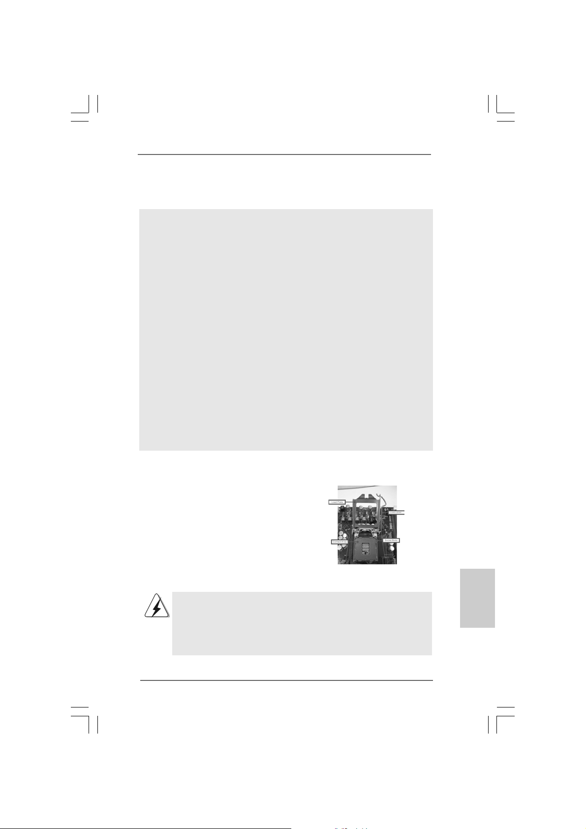
2. Installazione2. Installazione
2. Installazione
2. Installazione2. Installazione
Precauzioni preinstallazionePrecauzioni preinstallazione
Precauzioni preinstallazione
Precauzioni preinstallazionePrecauzioni preinstallazione
Leggere le seguenti precauzioni prima di installare componenti delle
schede madri o di ca mbi are le i mpostazioni delle schede ma dri.
1. Togliere il cavo dalla presa elettrica prima di toccare le componenti.
In caso contrario la schedamadre, le periferiche,
e/o i componenti possono subire gravi danni.
2. Per evitare che l’elettricità statica danneggi la scheda ma dre,NON
appoggi are la scheda ma dre su moquette, tappeti o tessuti simili.
Ricordarsi di indossare un braccialetto antistatico collegato a terra
o di toccare un oggetto posizionato a terra prima di maneggi are le
componenti.
3. Tenere i componenti per i bordi e non toccare i ICs.
4. Ogni volta che si disinstalla un componente, appoggiarlo su un
tappetino antistatico messo a terra o depositarlo nella borsa data in
dotazione con il componente.
5. Nell’usare i giraviti per fissare la scheda madre al telaio non serrare
eccessiva mente le viti! Altrimenti si rischia di danneggi are la
scheda madre.
2.1 Installazione del processore2.1 Installazione del processore
2.1 Installazione del processore
2.1 Installazione del processore2.1 Installazione del processore
Attenersi alle seguenti fasi per
installare la CPU Intel 1156-Pin.
(Piastra di
caricamento)
(Disposizione
comandi)
Vista del socket 1156-Pin
Prima da inserire la CPU da 1156-Pin nel socket, verificare che la
superficie della CPU sia pulita e che non ci siano pin piegati nel
socket. Non forzare l’inserimento della CPU nel socket se ci sono
pin piegati. In caso contrario la CPU potrebbe essere seriamente
danneggiata.
ASRock P55 Pro Motherboard
(Corpo socket)
8989
89
8989
ItalianoItaliano
ItalianoItaliano
Italiano
Page 90
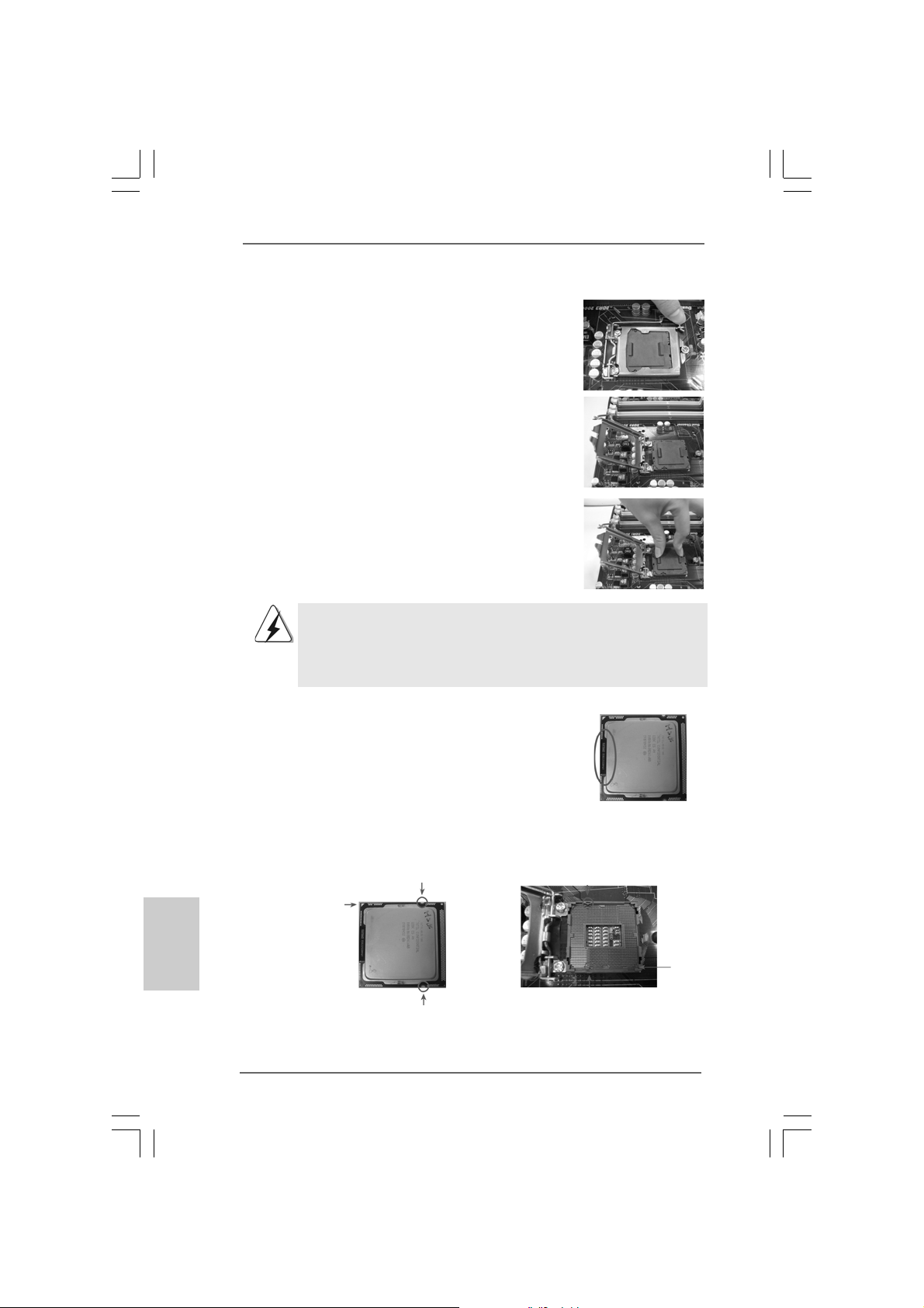
Fase 1. Aprire la presa:
Fase 1-1. Sbloccare la leva premendola
verso il basso ed allontanandola
dal gancio per liberare la linguetta.
Fase 1-2. Ruotare di circa 135 gradi la leva
di carico per aprirla
completamente.
Fase 1-3. Ruotare di circa 100 gradi la
piastra di carico per aprirla
completamente.
Fase 2. Rimuovere il cappuccio PnP
(Pick and Pla ce: prelievo e posizionamento).
1. Si raccomanda di utilizzare la linguetta del cappuccio per la
manipolazione ed evitare di far saltare via il cappuccio PnP.
2. Questo tappo deve essere inserito se se la scheda madre
deve essere restituita per l’assistenza.
Italiano
ItalianoItaliano
ItalianoItaliano
9090
90
9090
Fase 3. Inserire la CPU 1156-Pin:
Fase 3-1. T enere la CPU dai bordi segn ati con
linee nere.
Fase 3-2. Orientare il pacchetto con l’IHS
(Integrated Heat Sink: dispersore di
calore integrato) verso l’alto.
Individuare il Pin1 ed i due dentelli
chiave d’orienta mento.
Dente di orientamento
Pin1
Dente di orientamento
CPU da 1156-Pin
ASRock P55 Pro Motherboard
Linea nera
Tacca di allineamento
Pin1
Tacca di allineamento
Socket da 1156-Pin
Page 91
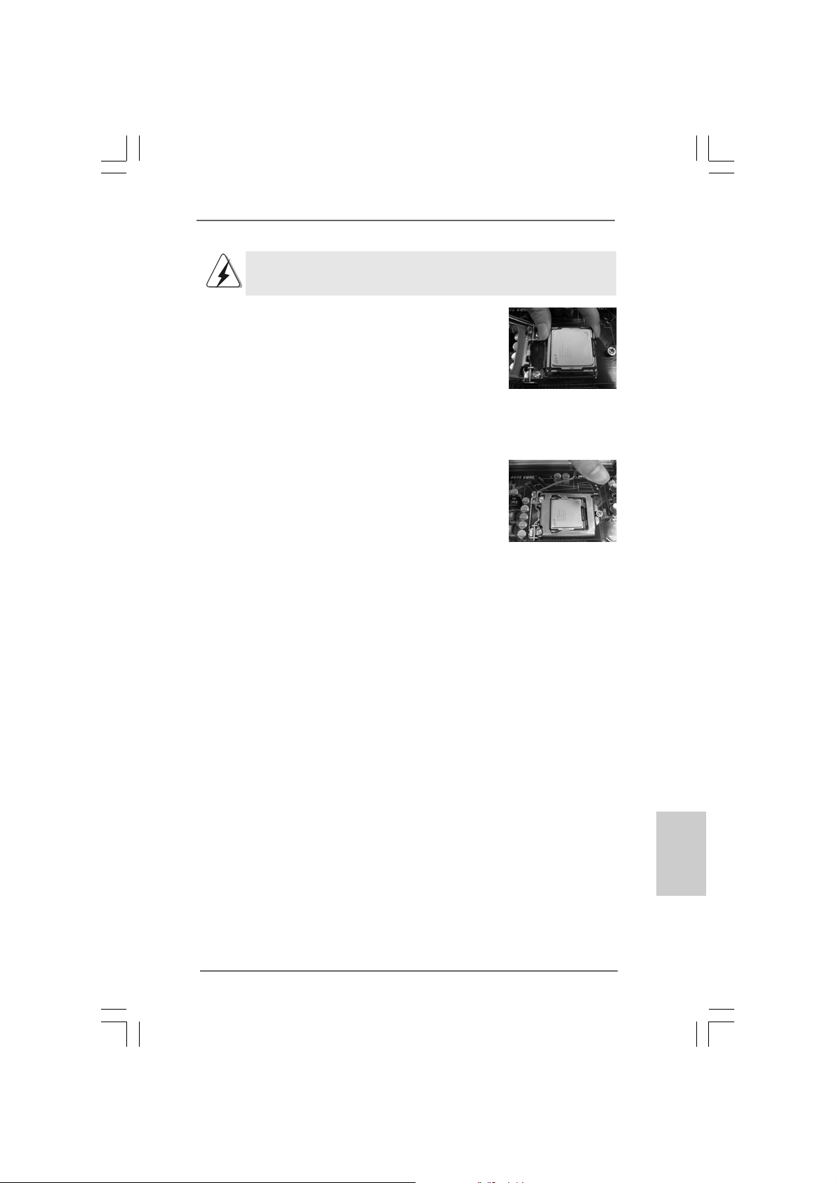
Per il corretto inserimento, verificare di far combaciare i due denti
di allineamento della CPU con le due tacche nel socket.
Fase 3-3. Collocare con delicatezza la CPU
sulla presa con un movimento
puramente verticale.
Fase 3-4. Verificare che la CPU sia all’interno
della presa e combaci in modo
appropri ato con le chi avi
d’orientamento.
Fase 4. Chiudere la presa:
Fase 4-1. Ruotare la piastra di carico
sull’IHS.
Fase 4-2. Bloccare la leva di carico mentre
si preme leggermente sulla piastra
di carico.
Fase 4-3. Fissare la leva di carico con la
linguetta della pia stra di carico che
si trova sulla parte inferiore della
linguetta di ritenzione della leva di
carico.
ASRock P55 Pro Motherboard
9191
91
9191
ItalianoItaliano
ItalianoItaliano
Italiano
Page 92
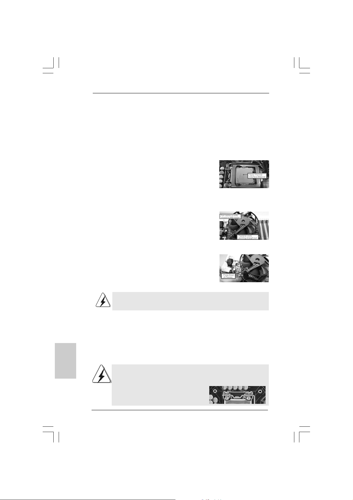
2.22.2
Installazione della ventola e del dissipatore diInstallazione della ventola e del dissipatore di
2.2
Installazione della ventola e del dissipatore di
2.22.2
Installazione della ventola e del dissipatore diInstallazione della ventola e del dissipatore di
calore della CPUcalore della CPU
calore della CPU
calore della CPUcalore della CPU
Per eseguire correttamente l’installazione si rimanda ai manuali di istruzione della
ventola e del dissipatore di calore della CPU.
Di seguito viene presentato un esempio che mostra l’installazione del dissipatore
per la CPU da 1156-Pin.
Fase1. Applicare il materiale di interfaccia termica al
dell’IHS sulla superficie del socket
(Applicare il materiale dell’interfaccia termica)
Fase 2. Collocare il dissipatore di calore nel socket.
Verificare che i cavi della ventola sono
orientati sul lato più vicino al connettore della
ventola della CPU presente sulla scheda
madre (CPU_FAN1, si veda pagina 2, No. 37).
Fase 3. Allineare i fastener con i fori passanti della
scheda madre.
Fase 4. Ruotare i fastener in senso orario, quindi
premere il cappuccio del fastener con il
pollice per installarlo e fissarlo. Ripetere la
stessa operazione con gli altri fa stener.
(Cavi della ventola sul lato più vicino
all’header della MB)
(Fori per fastener che allineati ad
fori passa nti)
(Premere verso il basso (4 punti))
Italiano
ItalianoItaliano
ItalianoItaliano
9292
92
9292
Se si premono i fastener verso il basso, senza ruotarli in senso
orario, il dissipatore non viene fissato bene alla scheda madre
Fase 5. Collegare il cavo di alimentazione della
ventola al connettore ventola della CPU sulla
scheda madre.
Fase 6. fissare il cavo in eccesso con fascette per
assicurare che il cavo non interferisca con il
funzionamento della ventola o che venga a
contatto con gli altri componenti.
Notare che questa scheda mare supporta l’opzione C.C.O. (Combo
Cooler Option), che fornisce la flessibilità di impiegare due tipi
diversi di dispersori di calore CPU, Socket LGA 775 e LGA 1156. I
fori di colore bianco sono per la ventola
CPU Socket LGA 1156.
ASRock P55 Pro Motherboard
Page 93
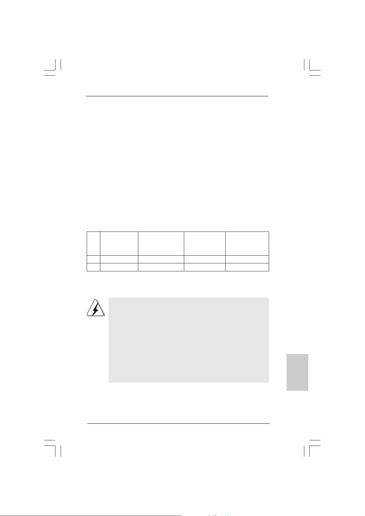
2.3 Installazione dei moduli di memoria (DIMM)2.3 Installazione dei moduli di memoria (DIMM)
2.3 Installazione dei moduli di memoria (DIMM)
2.3 Installazione dei moduli di memoria (DIMM)2.3 Installazione dei moduli di memoria (DIMM)
La scheda madre P55 Pro fornisce quattro alloggiamenti DIMM DDR3 (Double Data
Rate 3) a 240 pin, e supporta la tecnologia Dual Channel Memory. Per la
configurazione a due canali, è necessario installare sempre coppie identiche
(stessa marca, velocità, dimensioni e tipo di chi p) di DIMM DDR3 negli alloggiamenti
dello stesso colore. In altre parole, è necessario installare coppie identiche di DIMM
DDR3 nel canale doppio (DD R3_A1 e DDR3_B1; alloggiamenti bianco; vedere pag.
2 Nr. 5), per fare sì che la tecnologia Dual Channel Memory possa essere attivata.
Questa scheda madre consente anche di installare quattro DIMM DDR3 per la
configurazione a canale doppio.Questa scheda madre consente anche di
installare quattro DIMM DDR3 per configurazione a canale duale, si raccomanda di
installare DIMM DDR3 identiche nei quattro alloggia menti. Con sultare la Tabella
configurazione Memoria Canale Duale di seguito.
Configurazioni Dual Channel Memory
DDR3_A2 DDR3_A1 DDR3_B2 DDR3_B1
(alloggiamento (alloggiamento (alloggiamento (alloggiamento
blu) bianco) blu) bianco)
(1) - Popolato - Popolato
(2)* Popolato Popolato Popolato Popolato
* Per la configurazione (2), installare DDR3 DIMM identici nei quattro slot.
1. Se si vogliono installare due moduli di memoria, per ottenere
compatibilità ed affidabilità ottimali, si raccomanda di installarli negli
alloggia menti dello stesso colore. In altre parole: in stallare i moduli di
memoria o nella serie di alloggia menti bi anco (DD R3_A1 e DDR3_B1).
2. Se negli alloggiamenti DIMM di questa scheda madre è installato un
solo modulo di memoria, oppure sono installati tre moduli di memoria,
è impossibile attivare la tecnologia Dual Channel Memory.
3. Non è consentito installare la DDR o DDR2 nello slot DDR3,
altrimenti si possono danneggiare questa scheda madre e la
DIMM.
4. Installare il modulo di memoria nell’alloggio bianco (DDR3_B1) per la
prima priorità.
ASRock P55 Pro Motherboard
9393
93
9393
ItalianoItaliano
ItalianoItaliano
Italiano
Page 94
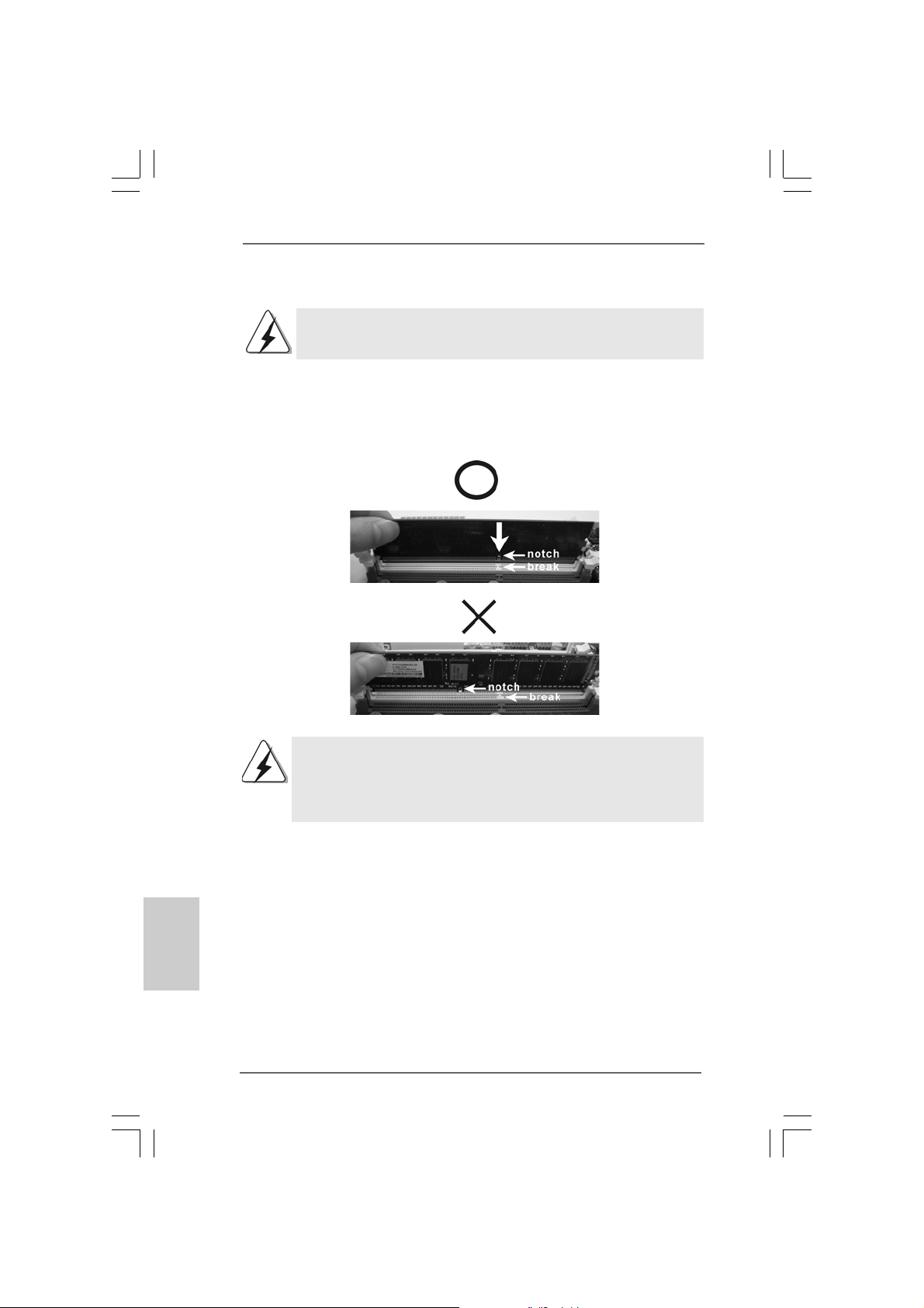
Installare una DIMMInstallare una DIMM
Installare una DIMM
Installare una DIMMInstallare una DIMM
Scollegare l’alimentazione elettrica prima di aggiungere o rimuovere i
DIMM o altri componenti del sistema.
Step 1. Sbloccare lo slot DIMM premendo i fermi che lo trattengono verso
l’esterno.
Step 2. Allineare una DIMM sullo slot così che il pettine della DIMM combaci con
la sua sede sullo slot.
Italiano
ItalianoItaliano
ItalianoItaliano
9494
94
9494
La DIMM può essere montata correttamente soltanto con un
orientamento. Se si dovesse installare a forza la DIMM nello slot con
un orientamento errato, si causerebbero danni permanenti alla
scheda madre e alla DIMM stessa.
Step 3. Inserire saldamente la DIMM nello slot fino a far scattare completamente
in posizione i fermagli di ritegno alle due estremità e fino ad installare
correttamente la DIMM nella sua sede.
ASRock P55 Pro Motherboard
Page 95
2.42.4
Slot di espansione (Slot PCI ed Slot PCI Express)Slot di espansione (Slot PCI ed Slot PCI Express)
2.4
Slot di espansione (Slot PCI ed Slot PCI Express)
2.42.4
Slot di espansione (Slot PCI ed Slot PCI Express)Slot di espansione (Slot PCI ed Slot PCI Express)
Sulla scheda madre P55 Pro c’è 2 slot PCI ed 4 slot PCI Express.
Slot PCI: Sono utilizzati per installare schede di espansione con Interfa cci a PCI
a 32-bit.
Slot PCI Express: L’alloggio PCIE1 / PCIE3 (PCIE x1; bianco) è usato per le
schede PCI Express x1 lane, come schede Gigabit LAN e
SATA2.
L’alloggio PCIE2 (PCIE x16; blu) è usato per le schede
grafiche PCI Express x16 lane, oppure è usato per
installare schede grafiche PCI Express per supportare la
funzione CrossFireXTM.
L’alloggio PCIE4 (PCIE x16; arancione) è usato per le
schede PCI Express x1 lane, come schede Gigabit LAN,
SATA2, eccetera, oppure è usato per installare schede
grafiche PCI Express per supportare la funzione
CrossFireXTM.
1. In modalità scheda VGA singola, si raccomanda di installare una
scheda video PCI Express x16 nell’alloggio PCIE2.
2. In modalità CrossFireXM, installare le schede video PCI Express
x16 negli alloggi PCIE2 e PCIE4. Quindi, l’alloggio PCIE2
lavoreranno a larghezza di banda x16 mentre gli alloggi PCIE4
lavorerà a larghezza di banda x4.
3. Collegare una ventola chassis al relativo connettore della
scheda madre (CHA_FAN1 or CHA_FAN2) quando si usano più
schede video per ottenere un migliore ambiente termico.
Installare una scheda di espansioneInstallare una scheda di espansione
Installare una scheda di espansione
Installare una scheda di espansioneInstallare una scheda di espansione
Step 1. Prima d’installare la scheda di espansione, assicurarsi che l’alimentazione
sia stata esclusa oppure che il cavo di alimentazione sia scollegato. Prima
di iniziare l’installazione, si prega di leggere la documentazione della scheda
di espansione e di ef fettuare le necessarie i mpostazioni del hardware.
Step 2. Rimuovere i ganci sullo slot che si intende utilizzare. Tenere a portata di mano
le viti.
Step 3. Allineare il connettore della scheda con lo slot e premere con decisione
finché la scheda è completa mente inserita nello slot.
Step 4. Agganciare la scheda allo chassis con le viti.
ASRock P55 Pro Motherboard
9595
95
9595
ItalianoItaliano
ItalianoItaliano
Italiano
Page 96

TMTM
TM
2.52.5
Guida operativa per CrossFireXGuida operativa per CrossFireX
2.5
Guida operativa per CrossFireX
2.52.5
Guida operativa per CrossFireXGuida operativa per CrossFireX
TMTM
TM
CrossFireXCrossFireX
CrossFireX
CrossFireXCrossFireX
Questa scheda madre supporta la funzione CrossFireXTM e Quad CrossFireXTM.
La tecnologia CrossFireXTM offre i mezzi più vantaggiosi possibile per combinare
più GPU (Graphics Processing Unit) ad altre prestazioni in un singolo PC.
Combinando una serie di diverse modalità operative con la progettazione software
intuitiva ed un meccanismo d’interconnessione innovativo, CrossFireXTM abilita il
massimo livello possibile di prestazioni e qualità d’immagine in qualsiasi
applicazione 3D. Correntemente la funzione CrossFireXTM è supportata solo dai
sistemi operativi Windows® XP con Service Pack 2 e VistaTM. La funzione Quad
CrossFireXTM è supportata solo dal sistema operativo Windows® VistaTM. Visitare il
sito AMD per gli aggiornamenti dei driver ATITM CrossFireXTM. Attenersi alle
procedure d’installazione, a pagina 16, per i dettagli.
2.6 “Surround Display”2.6 “Surround Display”
2.6 “Surround Display”
2.6 “Surround Display”2.6 “Surround Display”
Questa scheda madre supporta l’aggiornamento Surround Display. Con la scheda
integrativa PCI Express VGA, si possono sfruttare con facilità i benefici della
funzione Surround Display. Per le istruzioni dettagliate, fare riferimento al
documento nel seguente percorso sul CD di supporto:
..\ Surround Display Information
TMTM
TMTM
e Quad e Quad
e Quad
e Quad e Quad
Italiano
ItalianoItaliano
ItalianoItaliano
9696
96
9696
ASRock P55 Pro Motherboard
Page 97
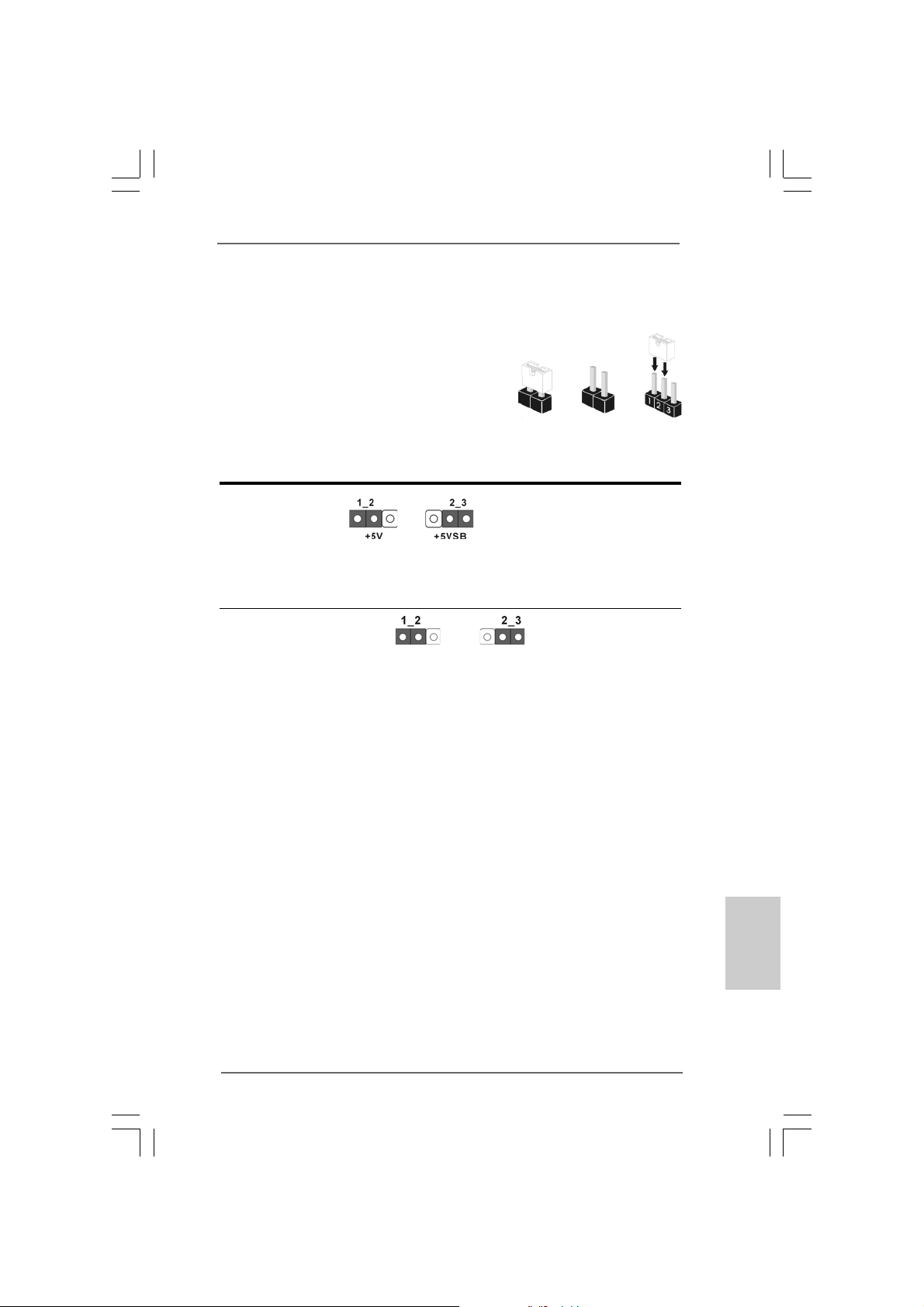
2.7 Setup dei Jumpers2.7 Setup dei Jumpers
2.7 Setup dei Jumpers
2.7 Setup dei Jumpers2.7 Setup dei Jumpers
L’illustrazione mostra come sono settati i
jumper. Quando il ponticello è posizionato
sui pin, il jumper è “CORTOCIRCUIT A TO”.
Se sui pin non ci sono ponticelli, il jumper
è “APERTO”. L’illustrazione mostra un
jumper a 3 pin in cui il pin1 e il pin2 sono
“CORTOCIRCUIT A TI” quando il ponticello
è posizionato su questi pin.
Jumper Settaggio del Jumper
PS2_USB_PWR1 Cortocircuitare pin2, pin3 per
(vedi p.2 Nr. 1) settare a +5VSB (standby) e
Nota: Per selezionare +5VSB, si richiedono almeno 2 Ampere e il consumo di
corrente in standby sarà maggiore.
Resettare la CMOS
(CLRCMOS1, jumper a 3 pin)
(vedi p.2 Nr. 15)
Nota: CLRCMOS1 permette di cancellare i dati pre senti nel CMOS. I dati del CMOS
comprendono le informazioni di configurazione quali la pa ssword di sistema,
data, ora, e i parametri di conf igurazione del sistema. Per cancellare e
ripristinare i parametri del sistema, spegnere il computer e togliere il cavo di
alimentazione dalla presa di corrente. Dopo aver lasciato tra scorrere 15
secondi, utilizzare un cappuccio jumper per cortocircuitare i pin 2 e 3 su
CLRCMOS1 per 5 secondi. Dopo aver cortocircuitato il jumper Clear CMOS
jumper, togliere il terminatore jumper. Non ca ncellare la CMOS subito dopo aver
aggiornato il BIOS. Se è necessario cancellare la CMOS un a volta completato
l’aggiorna mento del BIOS, è necessario ri avvi are pri ma il sistema, e poi
spegnerlo prima di procedere alla cancellazione della CMOS.
Impostazione
predefinita
CORTOCIRCUITATO APERTO
abilitare PS/2 o USB wake up
events.
Azzeramento
CMOS
ASRock P55 Pro Motherboard
9797
97
9797
ItalianoItaliano
ItalianoItaliano
Italiano
Page 98
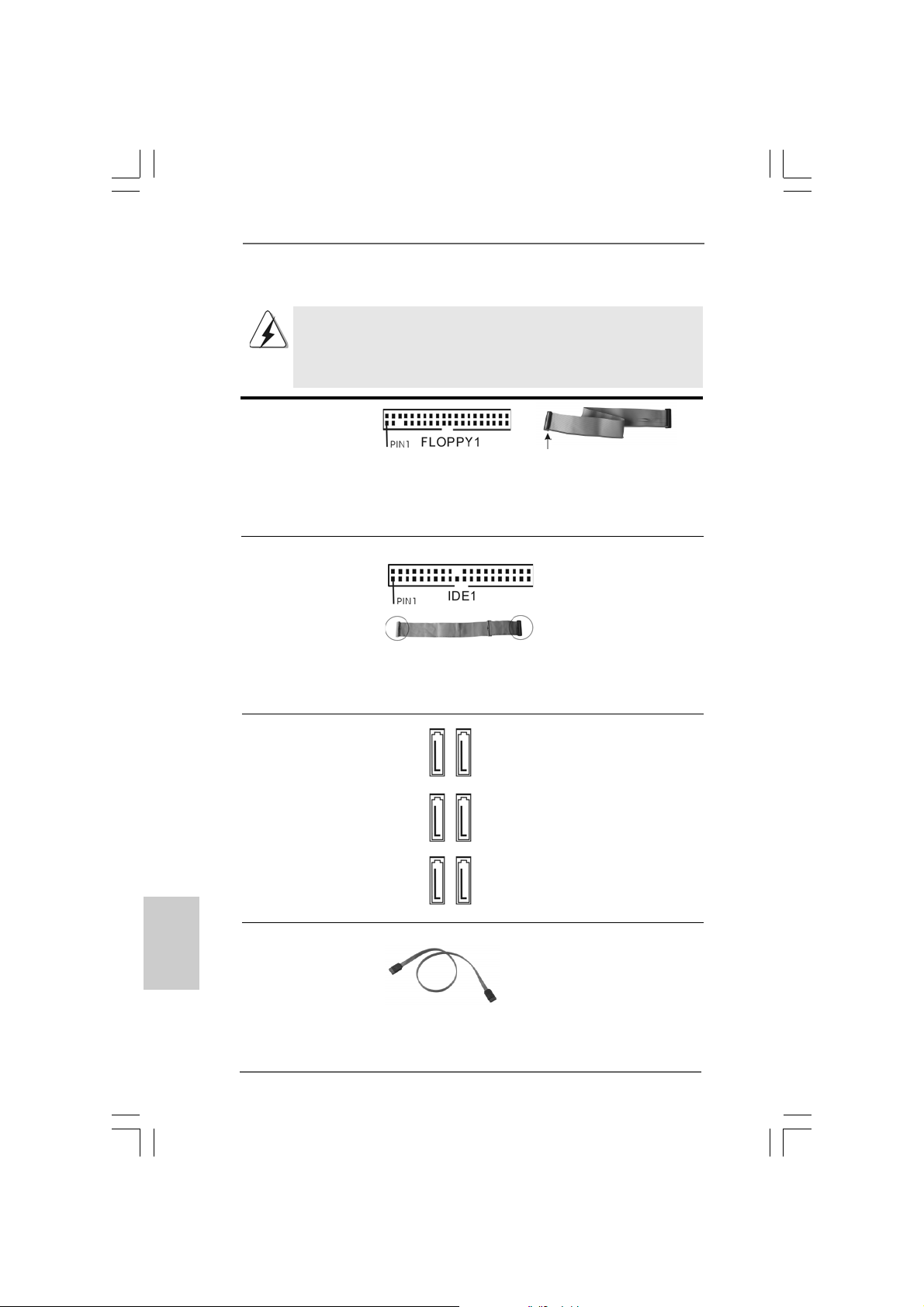
2.8 Collettori e Connettori su Scheda2.8 Collettori e Connettori su Scheda
2.8 Collettori e Connettori su Scheda
2.8 Collettori e Connettori su Scheda2.8 Collettori e Connettori su Scheda
I collettori ed i connettori su scheda NON sono dei jumper. NON installare
cappucci per jumper su questi collettori e connettori. L’installazione di
cappucci per jumper su questi collettori e connettori provocherà danni
permanenti alla scheda madre!
Connettore del
Floppy disk
(33-pin FLOPPY1)
(vedi p.2 Nr. 27)
Lato del Pin1 con la striscia
rossa
Nota: Assicurarsi che il lato del cavo con la striscia rossa sia inserito nel lato Pin1
del connettore.
Connettore IDE primario (blu)
(39-pin IDE1, vedi p.2 Nr. 14)
Connettore blu Connettore nero
alla schedamadre all’hard disk drive
Cavo ATA 66/100/133 a 80 Pin
Nota: Fate riferimento alle istruzioni del produttore del dispositivo IDE per maggiori
dettagli.
Connettori Serial A T AII Questi sei connettori Serial
(SATAII_1_2: AT AII (SA T AII) supporta no cavi
vedi p.2 Nr. 9) dati SATA per dispositivi di
(SATAII_3_4: immagazzina mento interni.
vedi p.2 Nr. 10) ATAII (SATAII) supportano cavi
(SAT AII_5_6: SATA per dispositivi di memoria
vedi p.2 Nr . 1 1) interni.
Italiano
ItalianoItaliano
ItalianoItaliano
9898
98
9898
SAT AII_5_6 SA T AII_3_4 SA T AII_1_2
Cavi dati Serial ATA (SATA) Una o altra estremità del cavo
(Opzionale) di dati SAT A può e ssere
collegata al disco rigido SATA /
SATAII o al connettore di SA T AII
su questa cartolina ba se.
ASRock P55 Pro Motherboard
Page 99
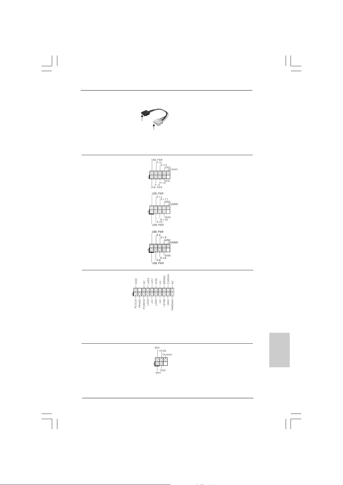
Cavo d’alimentazione Collegare l’estremità nera de
Serial A TA (SATA) cavo di alimentazione SATA al
(Opzionale) connettore di alimentazione del
Connettere
all’ailmentazione
dei dischi SATA
Connettere al
gruppo
di alimentazione
drive. Poi connettete l’estremità
bianca del cavo di ali mentazione
SAT A al connettore power
dell’alimentatore.
Collettore USB 2.0 Oltre alle sei porte USB 2.0
(9-pin USB12_13) predefinite nel pannello I/O, la
(vedi p.2 Nr. 23) scheda madre dispone di
tre intestazioni USB 2.0.
Ciascuna intestazione USB 2.0
supporta due porte USB 2.0.
(9-pin USB10_11)
(vedi p.2 Nr. 24)
(9-pin USB8_9)
(vedi p.2 Nr. 25)
Collettore TPM
(19-pin TPM1)
(vedi p.2 Nr. 19)
Questo connettore supporta un
sistema Trusted Platform Module
(TPM), che può archiviare in
sicurezza chiavi, certificati
digitali, password e dati. Un
sistema di TPM aiuta anche a
migliorare la sicurezza di rete,
protegge le identità digitali e
garantisce l’integrità della
piattaforma.
Collettore modulo infrarossi Questo collettore supporta
(5-pin IR1) moduli ad infrarossi optional
(vedi p.2 Nr. 21) per la trasmissione e la
ricezione senza fili.
ASRock P55 Pro Motherboard
9999
99
9999
ItalianoItaliano
ItalianoItaliano
Italiano
Page 100
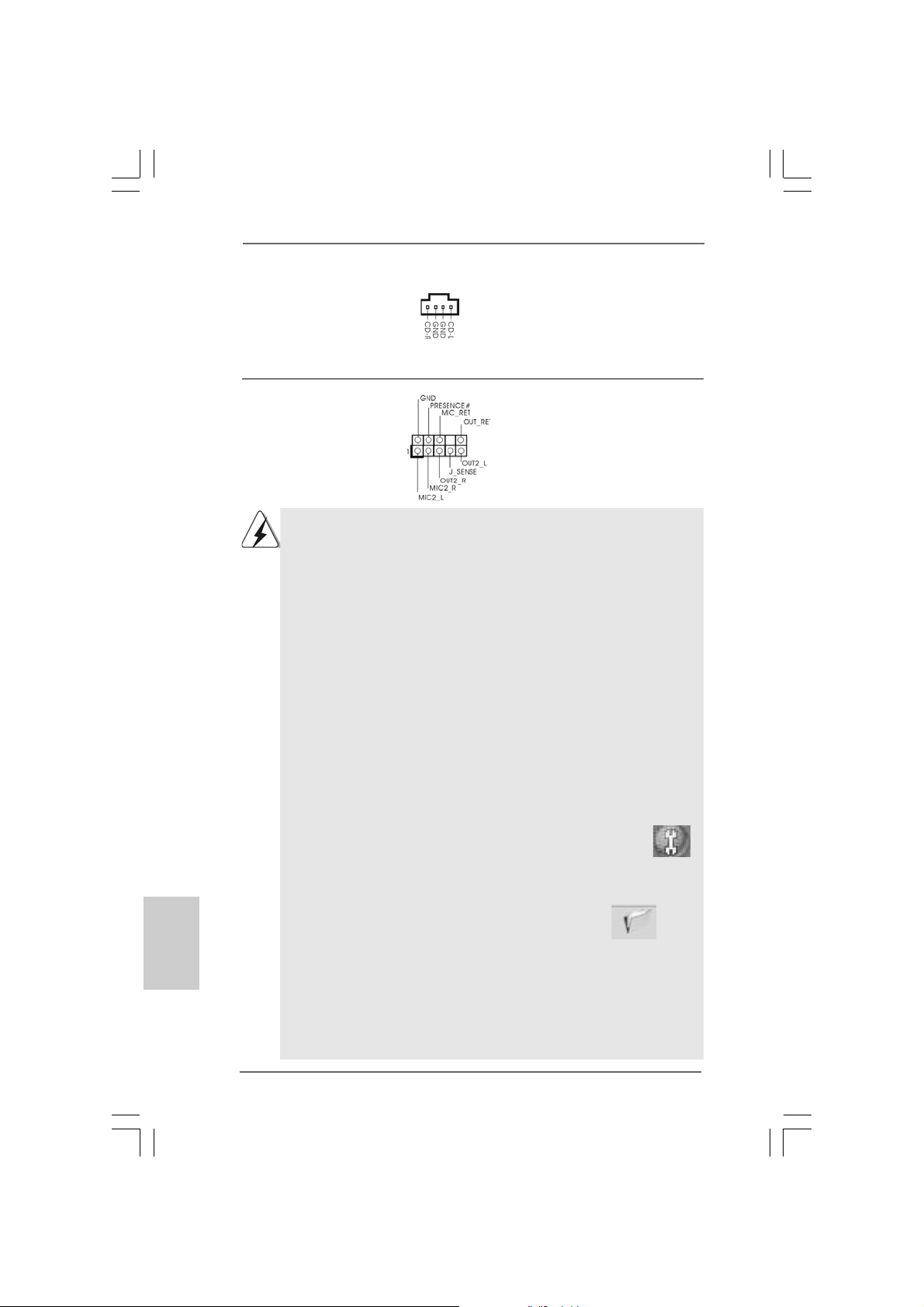
Connettori audio interni Permettono di ricevere input
(4-pin CD1) stereo audio da fonti di
(vedi p.2 Nr. 31) suono come CD-ROM, DVD -
CD1
ROM,TV tuner, o schede
MPEG.
Connettore audio sul È un’interfaccia per il cavo del
pannello frontale pannello audio. Che consente
(9-pin HD_AUDIO1) connessione facile e controllo
(vedi p.2 Nr. 30) dei dispositivi audio.
1. La caratteristica HDA (High Definition Audio) supporta il rilevamento dei
connettori, però il pannello dei cavi sul telaio deve supportare la funzione
HDA (High Definition Audio) per far sì che questa operi in modo corretto.
Attenersi alle istruzioni del nostro manuale e del manuale del telaio per
installare il sistema.
2. Se si utilizza un pannello audio AC’97, installarlo nell’intestazione audio
del pannello anteriore, come indicato di seguito:
A. Collegare Mic_IN (MIC) a MIC2_L.
B. Collegare Audio_R (RIN) a OUT2_R e Audio_L (LIN) ad OUT2_L.
C. Collegare Ground (GND) a Ground (GND).
D. MIC_RET e OUT_RET sono solo per il pannello audio HD. Non è
necessario collegarli per il pannello audio AC’97.
E. Entrare nel programma di impostazione BIOS. Entrare su Impostazioni
avanzate, quindi selezionare Configurazione chipset. Impostare
l’opzione Comando pannello anteriore da [Auto] a [Attivato].
F. Entrare nel sistema di Windows. Fare clic sull’icona situata nell’angolo
inferiore destro della barra delle applicazioni per entrare su Realtek HD
Audio Manager.
Per Windows® XP / XP 64-bit OS:
Fare clic su “Audio I/O”, selezionare “Impostazioni connettore” ,
Italiano
ItalianoItaliano
ItalianoItaliano
100100
100
100100
scegliere “Disattiva rilevazione presa pannello anteriore” e salvare la
modifica facendo clic su “OK”.
Per Windows® VistaTM / VistaTM 64-bit OS:
Cliccare sull‘icona in alto a destra “Folder” (“Cartella”) ,
selezionare “Disable front panel jack detection” “Disabilitare
individuazione presa pannello frontale”) e cliccare “OK” per
memorizzare.
G. Per attivare il microfono anteriore.
Per il sistema operativo Windows® XP / XP 64-bit:
Selezionare “Microfono anteriore” come dispositivo predefinito per la
registrazione. Per ascoltare la propria voce tramite il microfono
ASRock P55 Pro Motherboard
 Loading...