

Page 1

IMB-171-D
IMB-171-L
IMB-161-D
IMB-161-L
User Manual
Version 1.0
Published February 2013
Copyright©2013 ASRock INC. All rights reserved.
1
Page 2

Copyright Notice:
No part of this manual may be reproduced, transcribed, transmitted, or translated in
any language, in any form or by any means, except duplication of documentation by
the purchaser for backup purpose, without written consent of ASRock Inc.
Products and corporate names appearing in this manual may or may not be regis-
tered trademarks or copyrights of their respective companies, and are used only for
identication or explanation and to the owners’ benet, without intent to infringe.
Disclaimer:
Specications and information contained in this manual are furnished for informa-
tional use only and subject to change without notice, and should not be constructed
as a commitment by ASRock. ASRock assumes no responsibility for any errors or
omissions that may appear in this manual.
With respect to the contents of this manual, ASRock does not provide warranty of
any kind, either expressed or implied, including but not limited to the implied warran-
ties or conditions of merchantability or tness for a particular purpose.
In no event shall ASRock, its directors, ofcers, employees, or agents be liable for
any indirect, special, incidental, or consequential damages (including damages for
loss of prots, loss of business, loss of data, interruption of business and the like),
even if ASRock has been advised of the possibility of such damages arising from
any defect or error in the manual or product.
This device complies with Part 15 of the FCC Rules. Operation is subject to the fol-
lowing two conditions:
(1) this device may not cause harmful interference, and
(2) this device must accept any interference received, including interference that
may cause undesired operation.
CALIFORNIA, USA ONLY
The Lithium battery adopted on this motherboard contains Perchlorate, a toxic
substance controlled in Perchlorate Best Management Practices (BMP) regulations
passed by the California Legislature. When you discard the Lithium battery in Cali-
fornia, USA, please follow the related regulations in advance.
“Perchlorate Material-special handling may apply, see
www.dtsc.ca.gov/hazardouswaste/perchlorate”
ASRock Website: http://www.asrock.com
2
Page 3

Contents
1 Introduction ........................................................ 5
1.1 Package Contents ......................................................... 5
1.2 Specications (IMB-171-D) ............................................ 6
1.3 Specications (IMB-171-L) ............................................ 8
1.4 Specications (IMB-161-D) ............................................ 10
1.5 Specications (IMB-161-L) ............................................ 12
1.6 Motherboard Layout (IMB-171-D / IMB-171-L /
IMB-161-D / IMB-161-L) ................................................ 14
1.7 I/O Panel (IMB-171-D) ................................................... 16
1.8 I/O Panel (IMB-171-L) .................................................... 17
1.9 I/O Panel (IMB-161-D) ................................................... 18
1.10 I/O Panel (IMB-161-L) .................................................. 19
2 Installation .......................................................... 20
2.1 Screw Holes ................................................................... 20
2.2 Pre-installation Precautions ........................................... 20
2.3 Installation of Memory Modules (DIMM) ........................ 21
2.4 Expansion Slot .............................................................. 22
2.5 Jumpers Setup ............................................................... 23
2.6 Onboard Headers and Connectors ................................ 24
2.7 Serial ATA2 (SATA2) / Serial ATA3 (SATA3) Hard Disks
Installation ...................................................................... 29
2.8 Hot Plug and Hot Swap Functions for SATA2 / SATA3
HDDs ............................................................................ 29
2.9 Driver Installation Guide ............................................ 30
3 UEFI SETUP UTILITY ................................................ 31
3.1 Introduction .................................................................... 31
3.1.1 UEFI Menu Bar .................................................... 31
3.1.2 Navigation Keys ................................................... 32
3.2 Main Screen ................................................................... 32
3.3 Advanced Screen ........................................................... 33
3.3.1 CPU Conguration ............................................... 34
3.3.2 North Bridge Conguration................................... 37
3.3.3 South Bridge Conguration .................................. 38
3.3.4 Storage Conguration .......................................... 39
3.3.5 Intel(R) Rapid Start Technology ........................... 40
3.3.6 Intel(R) Smart Connect Technology ..................... 41
3.3.7 Super IO Conguration ........................................ 42
3.3.8 ACPI Conguration............................................... 43
3.3.9 USB Conguration ............................................... 44
3
Page 4

3.3.10 Trusted Computing ............................................. 45
3.4 Hardware Health Event Monitoring Screen ................... 46
3.5 Boot Screen ................................................................... 47
3.6 Security Screen ............................................................. 49
3.7 Exit Screen .................................................................... 50
4 Software Support ................................................ 51
4.1 Install Operating System ................................................ 51
4.2 Support CD Information ................................................. 51
4.2.1 Running Support CD ............................................ 51
4.2.2 Drivers Menu ........................................................ 51
4.2.3 Utilities Menu........................................................ 51
4.2.4 Contact Information .............................................. 51
4
Page 5
Chapter 1: Introduction
Thank you for purchasing ASRock IMB-171-D / IMB-171-L / IMB-161-D / IMB-161-L
motherboard, a reliable motherboard produced under ASRock’s consistently strin-
gent quality control. It delivers excellent performance with robust design conforming
to ASRock’s commitment to quality and endurance.
In this manual, chapter 1 and 2 contain introduction of the motherboard and step-
by-step guide to the hardware installation. Chapter 3 and 4 contain the conguration
guide to BIOS setup and information of the Support CD.
Because the motherboard specications and the BIOS software might be
updated, the content of this manual will be subject to change without no-
tice. In case any modications of this manual occur, the updated version
will be available on ASRock website without further notice. You may nd
the latest VGA cards and CPU support lists on ASRock website as well.
ASRock website http://www.asrock.com
If you require technical support related to this motherboard, please visit
our website for specic information about the model you are using.
www.asrock.com/support/index.asp
1.1 Package Contents
ASRock IMB-171-D / IMB-171-L / IMB-161-D / IMB-161-L Motherboard
(Mini-ITX Form Factor: 6.7-in x 6.7-in, 17.0 cm x 17.0 cm)
ASRock IMB-171-D / IMB-171-L / IMB-161-D / IMB-161-L Driver CD
ASRock IMB-171-D / IMB-171-L / IMB-161-D / IMB-161-L Jumper setting instruc-
tion
2 x Serial ATA (SATA) Data Cables
1 x Serial ATA (SATA) HDD Power Cable
2 x COM Port Cables
1 x I/O Panel Shield
5
Page 6
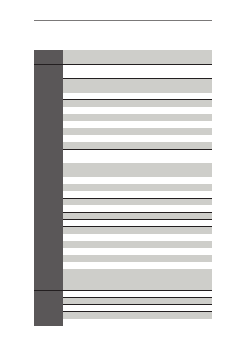
1.2 Specifications (IMB-171-D)
Form
Factor
Processor
System
Expansion
Slot
Memory
Graphics
Ethernet
SATA
Rear I/O
Dimensions Mini-ITX (6.7-in x 6.7-in)
CPU
Core
Number
Max Speed (By CPU)
L3 Cache (By CPU)
Chipset Q77
BIOS UEFI
PCI 0
Mini-PCIe 1 (Half Size)
mSATA 0
PCIe 1 (x16) (IVY Bridge: Gen3; Sandy Bridge: Gen2)
CFast Card
Socket
Technology
Max. 16GB
Socket 2 x SO-DIMM
Controller Intel® HD Graphics (By CPU)
VRAM Shared Memory
VGA No
LVDS No
HDMI Supports HDMI 1.4a, max resolution 1920x1200
DVI Support max resolution 1920x1200
Display Port Supports max resolution 2560x1600
Multi Display Yes
Ethernet 10/100/1000 Mbps
Controller GbE LAN1:Intel® 82583V, LAN2: Intel® 82579LM
Connector RJ-45 x 2 w/ LED
Max Data
Transfer
Rate
VGA 0
DVI 1 (DVI-I)
HDMI 1
DisplayPort 1
Ethernet 2
Socket LGA1155 for Intel® Core i7/i5/i3/Celeron
(Sandy Bridge and Ivy Bridge)
(By CPU, Max 4)
0
Dual Channel DDR3 1066/1333/1600 MHz
SDRAM
2 x SATA2 (3.0Gb/S), 2 x SATA3 (6.0Gb/S),
Supports RAID0/1/5/10
6
Page 7
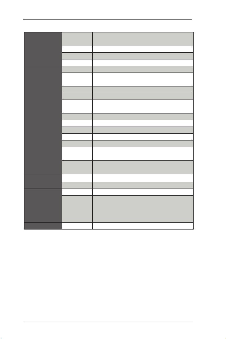
USB
Audio 2 (Mic-in, Line-out)
Serial 2 (RS-232/422/485)
PS/2 1 (Combo)
USB 4 (USB 2.0 compliant)
LVDS/
Inverter
VGA 0
Serial 4 (RS-232)
SATA
Internal
Connector
Watchdog
Timer
Power
Requirements
Environment Temperature 0ºC – 60ºC
mPCIe 1
Parallel 0
mSATA 0
IrDA 0
GPIO 8-bit 4 x GPI + 4 x GPO
SATA PWR
Output Con
Speaker
Header
Output Output from super I/O to drag RESETCON#
Interval 256 Segments, 0,1,2…255 Sec/Min
Input PWR ATX PWR (24+4 pin)
Power On
6 (2 x USB 2.0 compliant, 4 x USB 3.0
compliant)
0
2 x SATA2 (3.0Gb/s), 2 x SATA3 (6.0Gb/s),
Supports RAID0/1/5/10
0
0
AT/ATX Supported
-AT : Directly PWR on as power input ready
-ATX : Press button to PWR on after power
input ready
7
Page 8
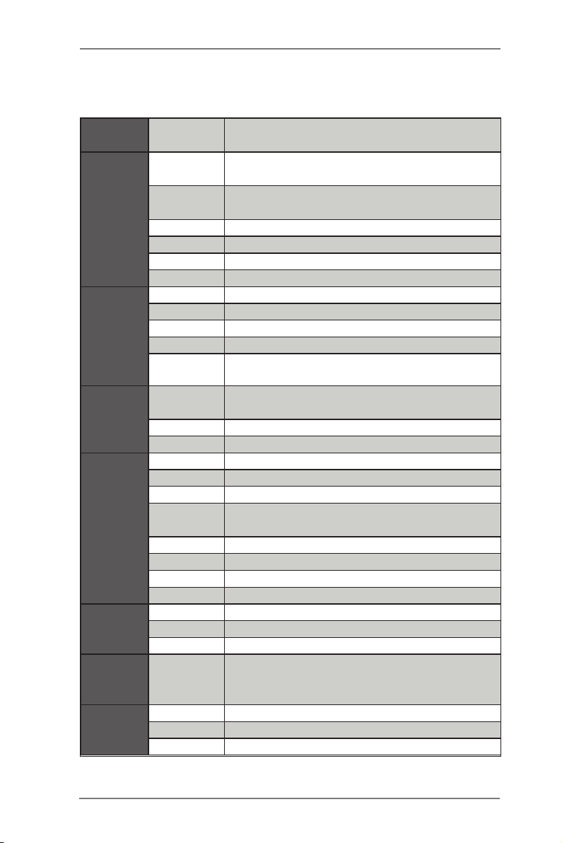
1.3 Specifications (IMB-171-L)
Form
Factor
Processor
System
Expansion
Slot
Memory
Graphics
Ethernet
SATA
Rear I/O
Dimensions Mini-ITX (6.7-in x 6.7-in)
CPU
Core
Number
Max Speed (By CPU)
L3 Cache (By CPU)
Chipset Q77
BIOS UEFI
PCI 0
Mini-PCIe 1 (Half Size)
mSATA 0
PCIe 1 (x16) (IVY Bridge: Gen3; Sandy Bridge: Gen2)
CFast Card
Socket
Technology
Max. 16GB
Socket 2 x SO-DIMM
Controller Intel® HD Graphics (By CPU)
VRAM Shared Memory
VGA Supports max resolution 2048x1536
LVDS
HDMI Supports HDMI 1.4a, max resolution 1920x1200
DVI No
Display Port No
Multi Display Yes
Ethernet 10/100/1000 Mbps
Controller GbE LAN1:Intel® 82583V, LAN2: Intel® 82579LM
Connector RJ-45 x 2 w/ LED
Max Data
Transfer
Rate
VGA 1
DVI 1
HDMI 1
Socket LGA1155 for Intel® Core i7/i5/i3/Celeron
(Sandy Bridge and Ivy Bridge)
(By CPU, Max 4)
0
Dual Channel DDR3 1066/1333/1600 MHz
SDRAM
Dual Channel 24-bit, support max resolution
1920x1200
2 x SATA2 (3.0Gb/S), 2 x SATA3 (6.0Gb/S),
Supports RAID0/1/5/10
8
Page 9
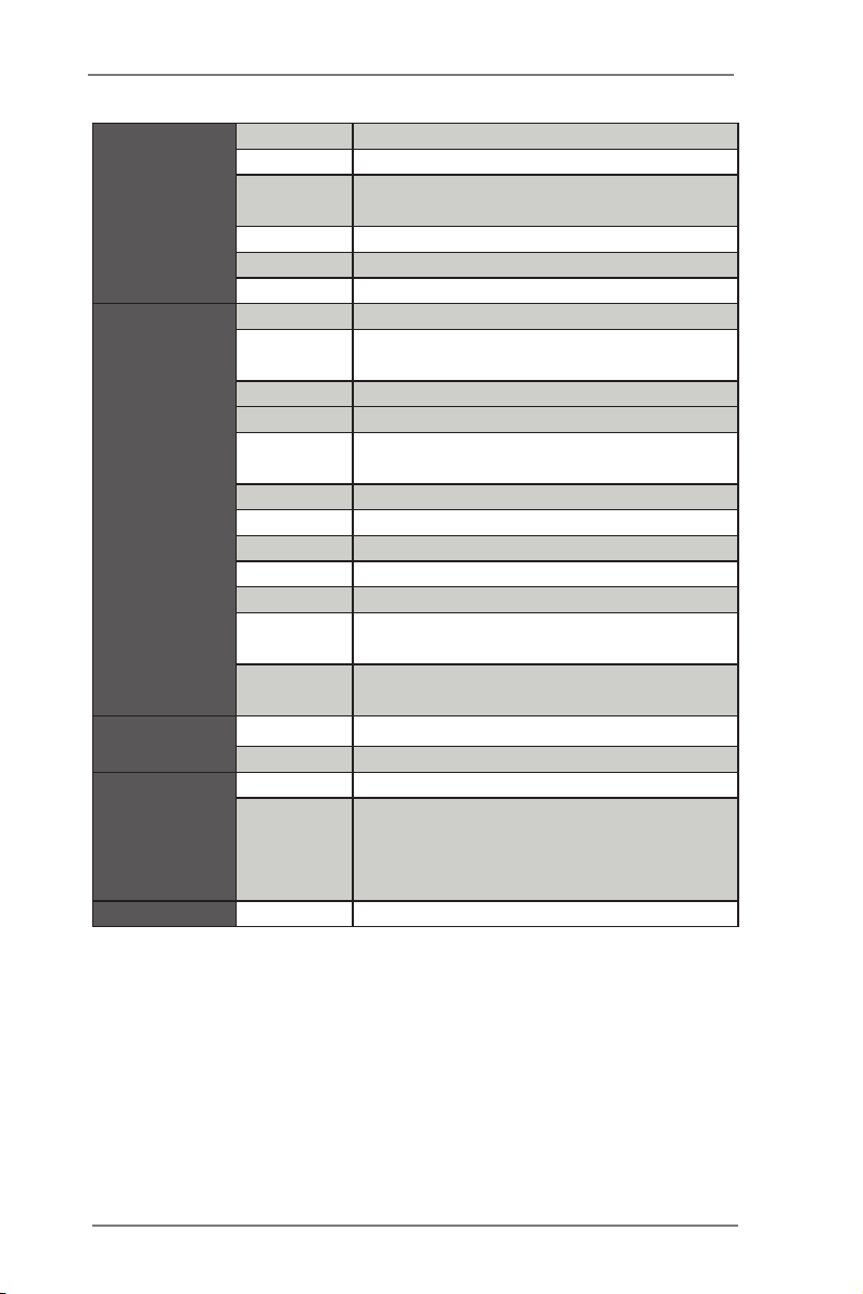
DisplayPort 0
Ethernet 2
USB
Audio 2 (Mic-in, Line-out)
Serial 2 (RS-232/422/485)
PS/2 1 (Combo)
USB 4 (USB 2.0 compliant)
LVDS/
Inverter
VGA 0
Serial 4 (RS-232)
SATA
Internal
Connector
Watchdog
Timer
Power
Requirements
Environment Temperature 0ºC – 60ºC
mPCIe 1
Parallel 0
mSATA 0
IrDA 0
GPIO 8-bit 4 x GPI + 4 x GPO
SATA PWR
Output Con
Speaker
Header
Output Output from super I/O to drag RESETCON#
Interval 256 Segments, 0,1,2…255 Sec/Min
Input PWR ATX PWR (24+4 pin)
Power On
6 (2 x USB 2.0 compliant, 4 x USB 3.0
compliant)
1/1
2 x SATA2 (3.0Gb/s), 2 x SATA3 (6.0Gb/s),
Supports RAID0/1/5/10
0
1
AT/ATX Supported
-AT : Directly PWR on as power input ready
-ATX : Press button to PWR on after power
input ready
9
Page 10
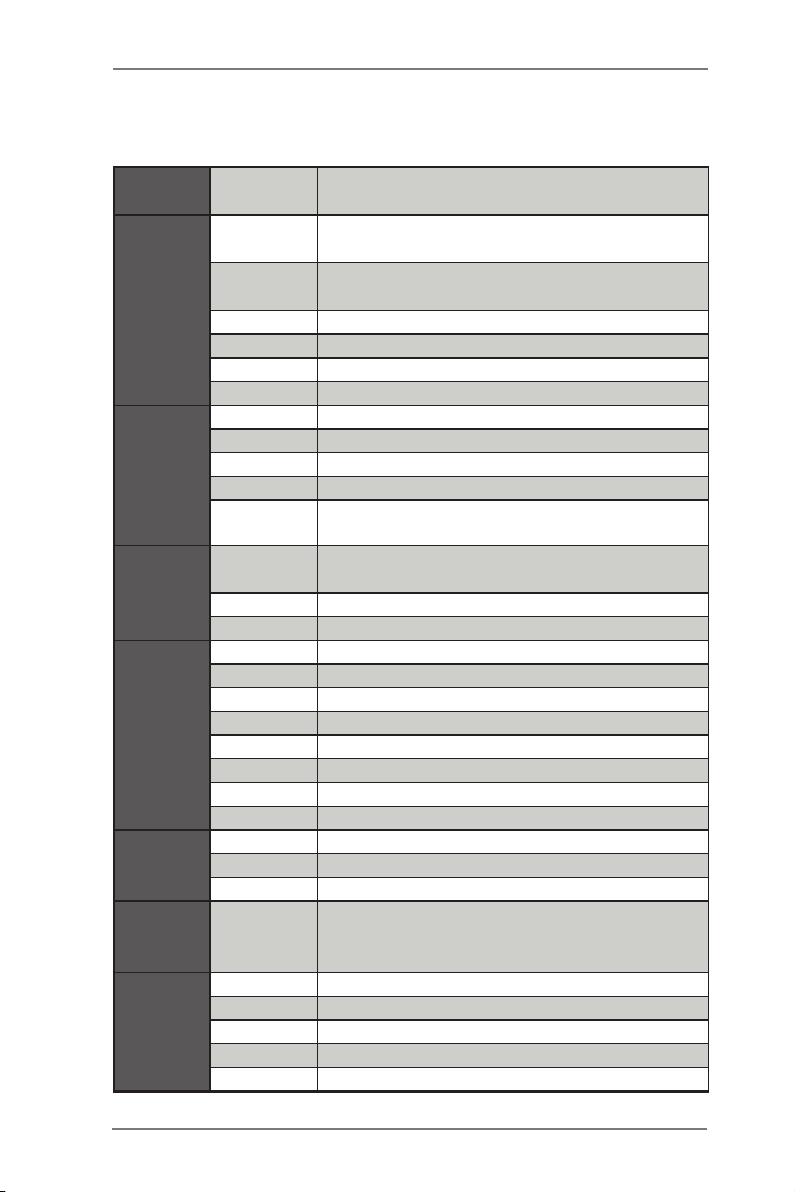
1.4 Specifications (IMB-161-D)
Form
Factor
Processor
System
Expansion
Slot
Memory
Graphics
Ethernet
SATA
Rear I/O
Dimensions Mini-ITX (6.7-in x 6.7-in)
CPU
Core
Number
Max Speed (By CPU)
L3 Cache (By CPU)
Chipset H61
BIOS UEFI
PCI 0
Mini-PCIe 1 (Half Size)
mSATA 0
PCIe 1 (x16) (IVY Bridge: Gen3; Sandy Bridge: Gen2)
CFast Card
Socket
Technology
Max. 16GB
Socket 2 x SO-DIMM
Controller Intel® HD Graphics (By CPU)
VRAM Shared Memory
VGA No
LVDS No
HDMI Supports HDMI 1.4a, max resolution 1920x1200
DVI Support max resolution 1920x1200
Display Port Supports max resolution 2560x1600
Multi Display Yes
Ethernet 10/100/1000 Mbps
Controller GbE LAN1:Intel® 82583V, LAN2: Intel® 82579V
Connector RJ-45 x 2 w/ LED
Max Data
Transfer
Rate
VGA 0
DVI 1 (DVI-I)
HDMI 1
DisplayPort 1
Ethernet 2
Socket LGA1155 for Intel® Core i7/i5/i3/Celeron
(Sandy Bridge and Ivy Bridge)
(By CPU, Max 4)
0
Dual Channel DDR3 1066/1333/1600 MHz
SDRAM
4 x SATA2 (3.0Gb/S)
10
Page 11
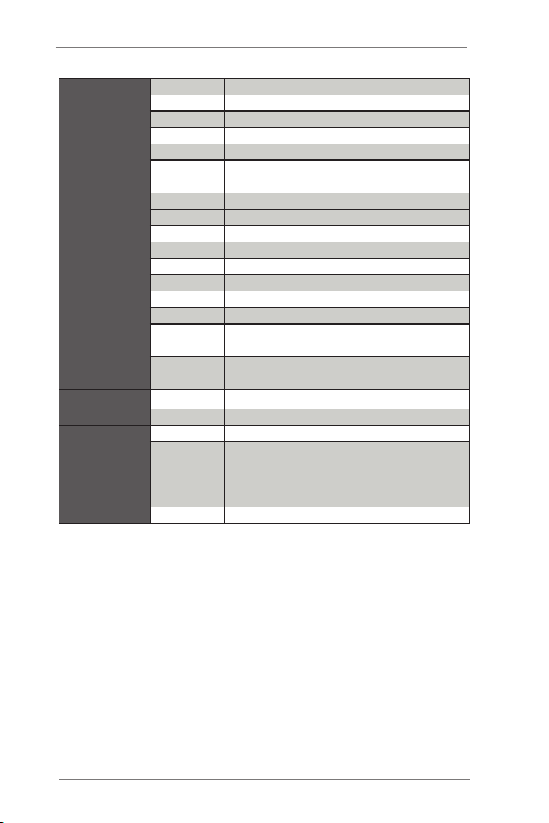
USB 6 (2 x USB 2.0 compliant)
Audio 2 (Mic-in, Line-out)
Serial 2 (RS-232/422/485)
PS/2 1 (Combo)
USB 2 (USB 2.0 compliant)
LVDS/
Inverter
VGA 0
Serial 4 (RS-232)
SATA
Internal
Connector
Watchdog
Timer
Power
Requirements
Environment Temperature 0ºC – 60ºC
mPCIe 1
Parallel 0
mSATA 0
IrDA 0
GPIO 8-bit 4 x GPI + 4 x GPO
SATA PWR
Output Con
Speaker
Header
Output Output from super I/O to drag RESETCON#
Interval 256 Segments, 0,1,2…255 Sec/Min
Input PWR ATX PWR (24+4 pin)
Power On
0
4 x SATA2 (3.0Gb/s)
0
0
AT/ATX Supported
-AT : Directly PWR on as power input ready
-ATX : Press button to PWR on after power
input ready
11
Page 12
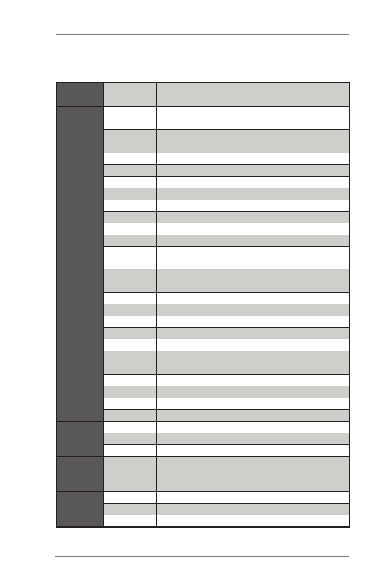
1.5 Specifications (IMB-161-L)
Form
Factor
Processor
System
Expansion
Slot
Memory
Graphics
Ethernet
SATA
Rear I/O
Dimensions Mini-ITX (6.7-in x 6.7-in)
CPU
Core
Number
Max Speed (By CPU)
L3 Cache (By CPU)
Chipset H61
BIOS UEFI
PCI 0
Mini-PCIe 1 (Half Size)
mSATA 0
PCIe 1 (x16) (IVY Bridge: Gen3; Sandy Bridge: Gen2)
CFast Card
Socket
Technology
Max. 16GB
Socket 2 x SO-DIMM
Controller Intel® HD Graphics (By CPU)
VRAM Shared Memory
VGA Supports max resolution 2048 x 1536
LVDS
HDMI Supports HDMI 1.4a, max resolution 1920x1200
DVI No
Display Port No
Multi Display Yes
Ethernet 10/100/1000 Mbps
Controller GbE LAN1:Intel® 82583V, LAN2: Intel® 82579V
Connector RJ-45 x 2 w/ LED
Max Data
Transfer
Rate
VGA 1
DVI 0
HDMI 1
Socket LGA1155 for Intel® Core i7/i5/i3/Celeron
(Sandy Bridge and Ivy Bridge)
(By CPU, Max 4)
0
Dual Channel DDR3 1066/1333/1600 MHz
SDRAM
Dual Channel 24-bit, support max resolution
1920x1200
4 x SATA2 (3.0Gb/S)
12
Page 13
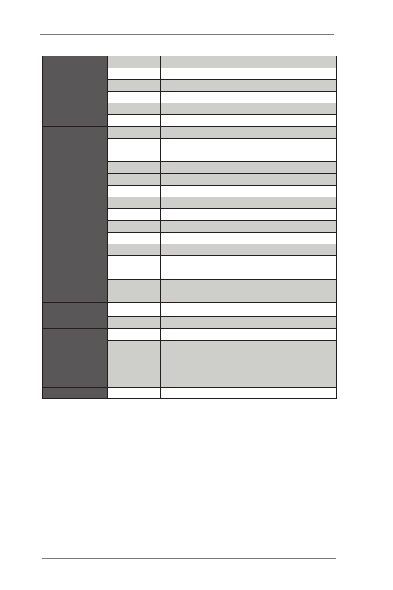
DisplayPort 0
Ethernet 2
USB 6 (2 x USB 2.0 compliant)
Audio 2 (Mic-in, Line-out)
Serial 2 (RS-232/422/485)
PS/2 1 (Combo)
USB 2 (USB 2.0 compliant)
LVDS/
Inverter
VGA 0
Serial 4 (RS-232)
SATA 4 x SATA2 (3.0Gb/s)
Internal
Connector
Watchdog
Timer
Power
Requirements
Environment Temperature 0ºC – 60ºC
mPCIe 1
Parallel 0
mSATA 0
IrDA 0
GPIO 8-bit 4 x GPI + 4 x GPO
SATA PWR
Output Con
Speaker
Header
Output Output from super I/O to drag RESETCON#
Interval 256 Segments, 0,1,2…255 Sec/Min
Input PWR ATX PWR (24+4 pin)
Power On
0
0
1
AT/ATX Supported
-AT : Directly PWR on as power input ready
-ATX : Press button to PWR on after power
input ready
13
Page 14
ATXP WR1
Intel
Q77/H61
DDR 3_A 1
DDR 3_B 1
PCIE 1
1
HD_AUDIO 1
CMOS
Batte ry
HDLED RE SET
PLED PWRBTN
PANEL1
1
AUDIO
CODEC
SATA_3
CLRCMOS1
1
CPU_FAN1
17. 0cm ( 6. 7 i n)
17. 0cm ( 6. 7 i n)
USB6_7
1
USB8_9
1
1
CI1
1
CI2
JGPIO_PWR1
1
PWR_JP1
1
Top:
RJ-4 5
USB
3.0 /2. 0
T: US B0
B: USB 1
USB 2. 0
T: US B2
B: USB 3
HDM I
1
LVDS1
BLT_PWR1
1
BLT_VOL1
1
BUZZ 1
Top:
Lin e O ut
Bot to m:
Mic In
MIN I_P CI E1
SPEAKER1
1
1
JGPI O1
COM 2
DVI 1/ VG A1
1
2
3*
4
5
6
7
9
10
8
12
13
14
16
15
17*
18*
19
20
21
22
23
24*
25
26
27
28
29
30
31
3233
COM 1
PS2
Keyb oard
/Mou se
DISP LAY1
TPM1
1
PNL_PWR1
1
BKT_PWR1
1
COM4
1
COM3
1
1
COM6
1
ATX12V1
CHA_FAN1
SATA_2
SATA_1
SATA_0
Top:
RJ-4 5
USB
3.0 /2. 0
T: US B4
B: USB 5
BIOS
ROM
11
COM5
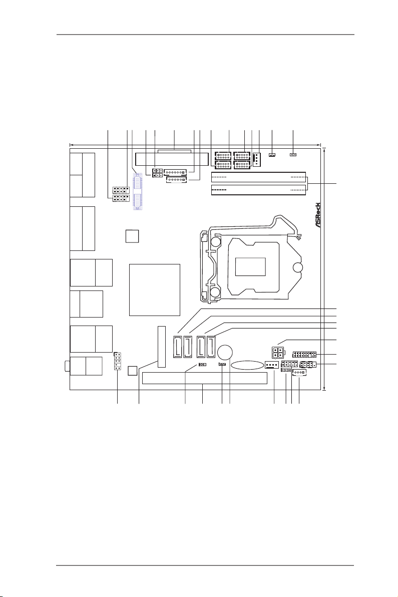
1.6 Motherboard Layout
(IMB-171-D / IMB-171-L / IMB-161-D / IMB-161-L)
14
Page 15

1 USB2.0 Header (USB8_9)
2 USB2.0 Header (USB6_7)
3* LVDS Panel Connector (For IMB-171-L / IMB-161-L only)
4 Panel Power Selection
5
Backlight Power Selection
6 24-pin ATX Power Input Connector
7 Backlight & Amp Volume Control
8 Inverter Power control Wafer
9 COM Port Header (COM3)
10 COM Port Header (COM4)
11 COM Port Header (COM5)
12 COM Port Header (COM6)
13
14 Chassis Intrusion Header 2
15 Chassis Intrusion Header 1
16 2 x SO-DIMM
17*
IMB-161-D / IMB-161-L: SATA2
18*
IMB-161-D / IMB-161-L: SATA2
19
20
21
22 TPM Header
23
24* 3W Audio AMP Output Wafer
25 Digital Input / Output Pin Header
26 Digital Input / Output Power select
27
28 Buzzer
29 Clear CMOS Header
30 PCIE1 Slot
31 ATX/AT Mode Selection
32 mini-PCIE Slot
33
4-Pin CPU FAN Connector (+12V)
IMB-171-D / IMB-171-L: SATA3
IMB-171-D / IMB-171-L: SATA3
SATA2
SATA2
4-pin ATX Power Input Connector
System Panel Header
(For IMB-171-L / IMB-161-L only)
4-Pin Chassis FAN Connector (+12V)
Front Panel Audio Header
15
Page 16
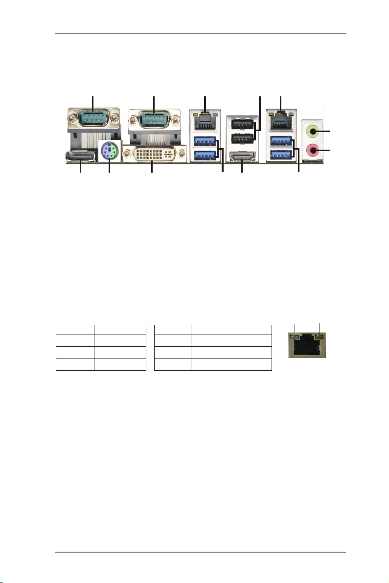
1.4 I/O Panel (IMB-171-D)
1
2
5
3
4
6
7
9
13
1 COM Port (COM1)
2 COM Port (COM2)
* 3 LAN RJ-45 Port
4 USB 2.0 Ports (USB23)
* 5 LAN RJ-45 Port
6 Line out (Lime)
7 Microphone (Pink)
* There are two LED next to the LAN port. Please refer to the table below for the LAN port LED
indications.
Activity/Link LED SPEED LED
Status Description Status Description
12
11
LAN Port LED Indications
10
8 USB 3.0 Ports (USB_45)
9 HDMI Port (HDMI1)
10 USB 3.0 Ports (USB_01)
11 DVI Port (DVI1)
12 PS/2 Mouse/Keyboard Port
13 DisplayPort (DP1)
8
ACT/LINK
LED
SPEED
LED
Off No Link Off 10Mbps connection
Blinking Data Activity Orange 100Mbps connection
On Link Green 1Gbps connection
LAN Port
16
Page 17
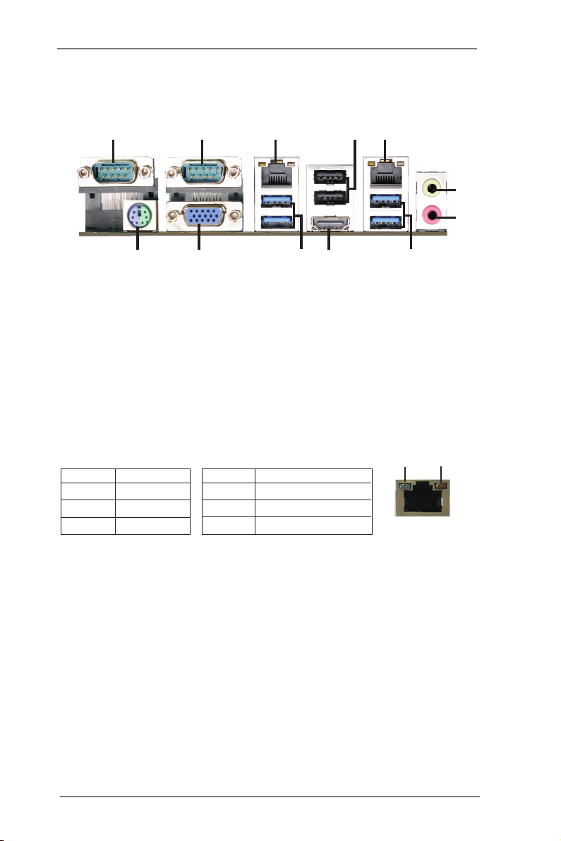
1.5 I/O Panel (IMB-171-L)
1
2
5
3
4
6
7
9
12
1 COM Port (COM1)
2 COM Port (COM2)
* 3 LAN RJ-45 Port
4 USB 2.0 Ports (USB23)
* 5 LAN RJ-45 Port
6 Line out (Lime)
* There are two LED next to the LAN port. Please refer to the table below for the LAN port LED
indications.
Activity/Link LED SPEED LED
Status Description Status Description
11
LAN Port LED Indications
10
7 Microphone (Pink)
8 USB 3.0 Ports (USB_45)
9 HDMI Port (HDMI1)
10 USB 3.0 Ports (USB_01)
11 VGA Port (VGA1)
12 PS/2 Mouse/Keyboard Port
8
ACT/LINK
LED
SPEED
LED
Off No Link Off 10Mbps connection
Blinking Data Activity Orange 100Mbps connection
On Link Green 1Gbps connection
LAN Port
17
Page 18
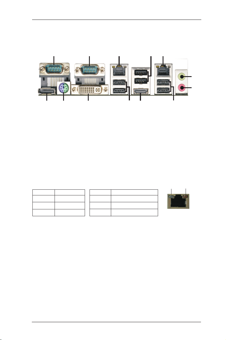
1.6 I/O Panel (IMB-161-D)
1
2
5
3
4
6
7
9
13
1 COM Port (COM1)
2 COM Port (COM2)
* 3 LAN RJ-45 Port
4 USB 2.0 Ports (USB23)
* 5 LAN RJ-45 Port
6 Line out (Lime)
7 Microphone (Pink)
* There are two LED next to the LAN port. Please refer to the table below for the LAN port LED
indications.
Activity/Link LED SPEED LED
Status Description Status Description
12
11
LAN Port LED Indications
10
8 USB 2.0 Ports (USB_45)
9 HDMI Port (HDMI1)
10 USB 2.0 Ports (USB_01)
11 DVI Port (DVI1)
12 PS/2 Mouse/Keyboard Port
13 DisplayPort (DP1)
8
ACT/LINK
LED
SPEED
LED
Off No Link Off 10Mbps connection
Blinking Data Activity Orange 100Mbps connection
On Link Green 1Gbps connection
LAN Port
18
Page 19
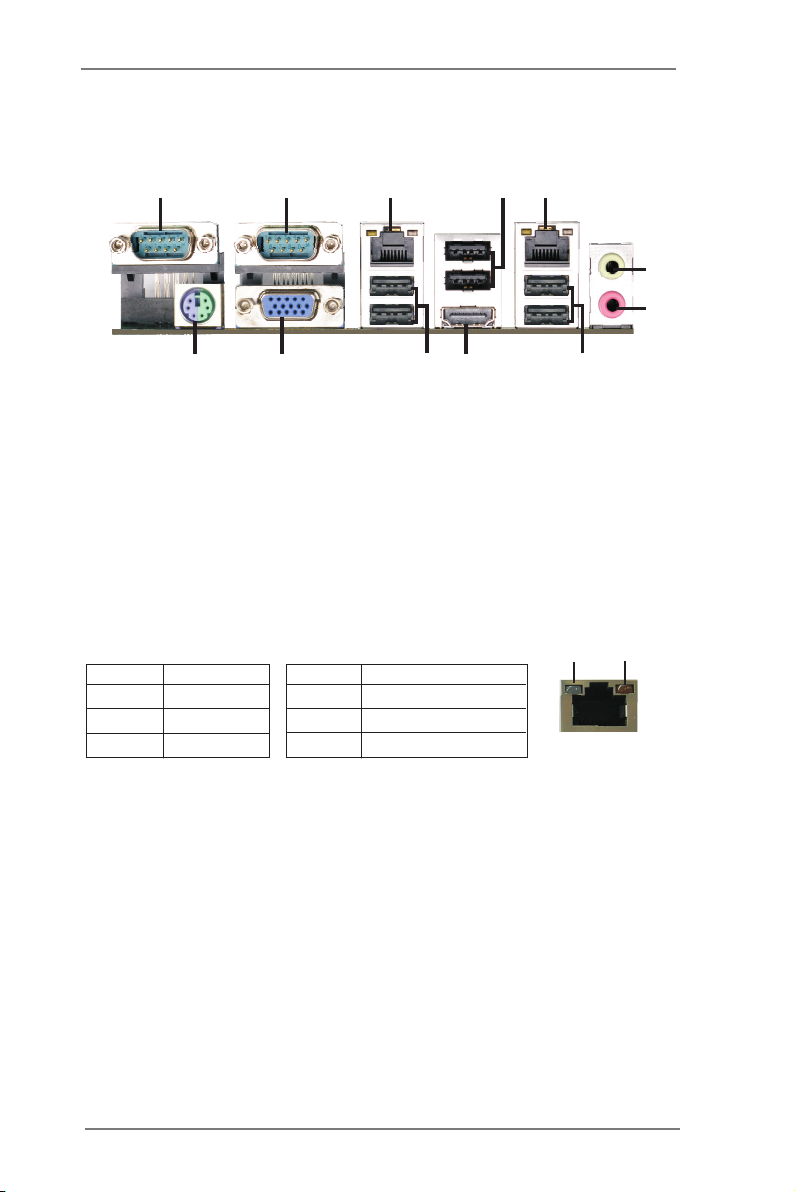
1.7 I/O Panel (IMB-161-L)
1
2
5
3
4
6
7
9
12
1 COM Port (COM1)
2 COM Port (COM2)
* 3 LAN RJ-45 Port
4 USB 2.0 Ports (USB23)
* 5 LAN RJ-45 Port
6 Line out (Lime)
* There are two LED next to the LAN port. Please refer to the table below for the LAN port LED
indications.
Activity/Link LED SPEED LED
Status Description Status Description
11
LAN Port LED Indications
10
7 Microphone (Pink)
8 USB 2.0 Ports (USB_45)
9 HDMI Port (HDMI1)
10 USB 2.0 Ports (USB_01)
11 VGA Port (VGA1)
12 PS/2 Mouse/Keyboard Port
8
ACT/LINK
LED
SPEED
LED
Off No Link Off 10Mbps connection
Blinking Data Activity Orange 100Mbps connection
On Link Green 1Gbps connection
LAN Port
19
Page 20
Chapter 2: Installation
This is a Mini-ITX form factor (6.7" x 6.7", 17.0 x 17.0 cm) motherboard. Before you
install the motherboard, study the conguration of your chassis to ensure that the
motherboard ts into it.
motherboard. Failure to do so may cause physical injuries to you and
damages to motherboard components.
Make sure to unplug the power cord before installing or removing the
2.1 Screw Holes
Place screws into the holes to secure the motherboard to the chassis.
Do not over-tighten the screws! Doing so may damage the motherboard.
2.2 Pre-installation Precautions
Take note of the following precautions before you install motherboard components
or change any motherboard settings.
1. Unplug the power cord from the wall socket before touching any component.
2. To avoid damaging the motherboard components due to static electricity,
NEVER place your motherboard directly on the carpet or the like. Also
remember to use a grounded wrist strap or touch a safety grounded object
before you handle components.
3. Hold components by the edges and do not touch the ICs.
4. Whenever you uninstall any component, place it on a grounded antistatic pad or
in the bag that comes with the component.
Before you install or remove any component, ensure that the power is
switched off or the power cord is detached from the power supply.
Failure to do so may cause severe damage to the motherboard, peripherals,
and/or components.
20
Page 21
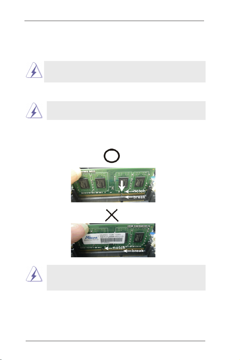
2.3 Installation of Memory Modules (SO-DIMM)
This motherboard provides two 204-pin DDR3 (Double Data Rate 3) SO-DIMM
slots.
It is not allowed to install a DDR or DDR2 memory module into DDR3
slot; otherwise, this motherboard and SO-DIMM may be damaged.
Installing a SO-DIMM
Please make sure to disconnect power supply before adding or
removing SO-DIMMs or the system components.
Step 1. Unlock a SO-DIMM slot by pressing the retaining clips outward.
Step 2. Align a SO-DIMM on the slot such that the notch on the SO-DIMM
matches the break on the slot.
The SO-DIMM only ts in one correct orientation. It will cause perma-
nent damage to the motherboard and the SO-DIMM if you force the SO-
DIMM into the slot at incorrect orientation.
Step 3. Firmly insert the SO-DIMM into the slot until the retaining clips at both
ends fully snap back in place and the SO-DIMM is properly seated.
21
Page 22

2.4 Expansion Slots (PCI Express and mini-PCIe Slots)
There is 1 PCI Express slot and 1 mini-PCIe slot on this motherboard.
PCIE slots:
PCIE1 (PCIE x16 slot; Blue) is used for PCI Express x16 lane width
graphics cards.
MINI_PCIE1 (mini-PCIe slot) is used for PCI Express mini cards.
Installing an expansion card
Step 1. Before installing the expansion card, please make sure that the power
supply is switched off or the power cord is unplugged. Please read the
documentation of the expansion card and make necessary hardware
settings for the card before you start the installation.
Step 2. Remove the system unit cover (if your motherboard is already installed
in a chassis).
Step 3. Remove the bracket facing the slot that you intend to use. Keep the
screws for later use.
Step 4. Align the card connector with the slot and press rmly until the card is
completely seated on the slot.
Step 5. Fasten the card to the chassis with screws.
Step 6. Replace the system cover.
22
Page 23
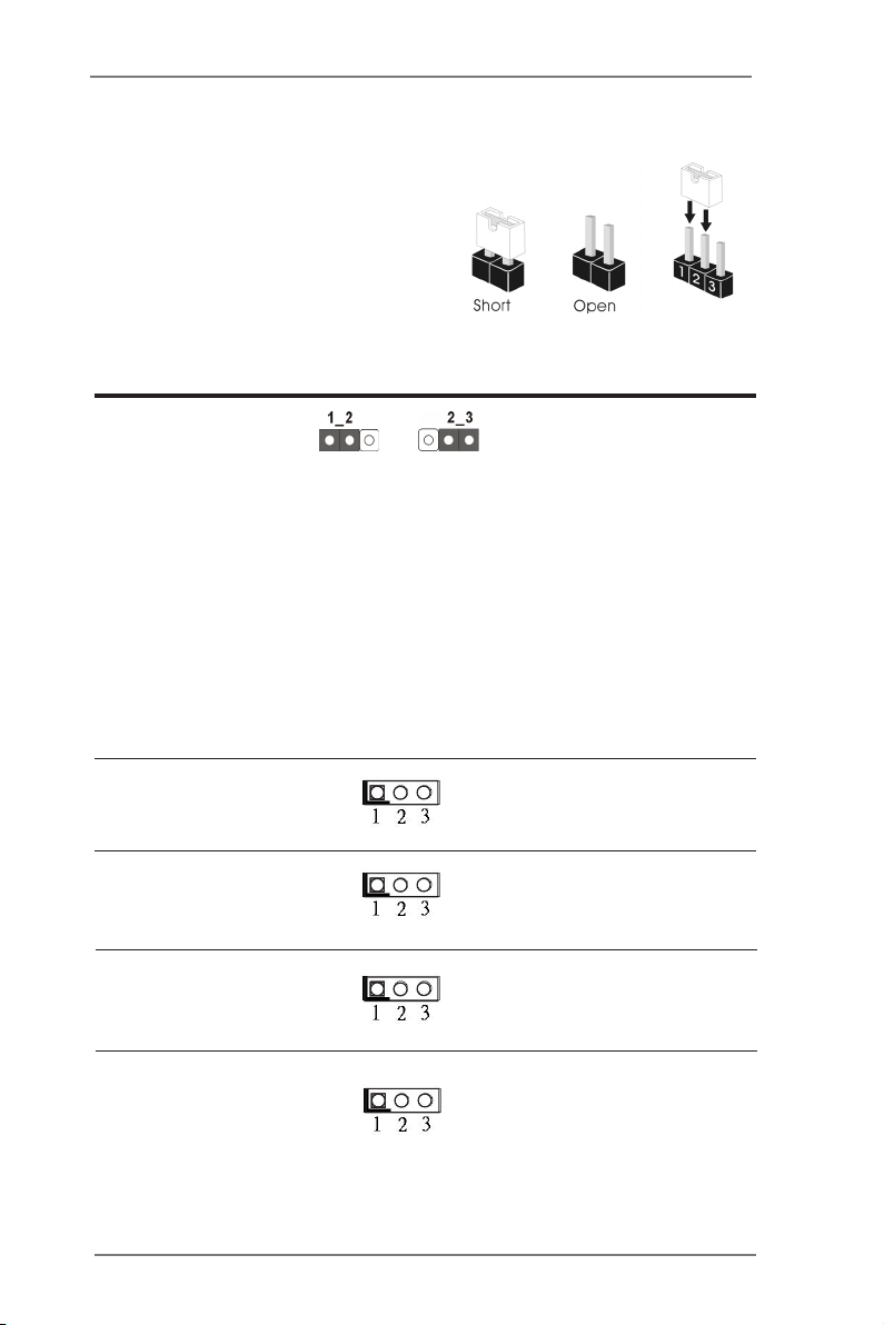
2.5 Jumpers Setup
The i llu strat ion shows how ju mpers are
setup. When the jumper cap is placed on
pins, the jumper is “Short”. If no jumper cap
is placed on pins, the jumper is “Open”. The
illustra ti on shows a 3-p in jumper whose
pin1 and pin2 are “Short” when jumper cap
is placed on these 2 pins.
Jumper Setting Description
Clear CMOS Jumper
(3-pin CLRCMOS1)
(see p.14, No. 29)
Note: CLRCMOS1 allows you to clear the data in CMOS. To clear and reset the
system parameters to default setup, please turn off the computer and unplug
the power cord from the power supply. After waiting for 15 seconds, use a
jumper cap to short pin2 and pin3 on CLRCMOS1 for 5 seconds. However,
please do not clear the CMOS right after you update the BIOS. If you need
to clear the CMOS when you just nish updating the BIOS, you must boot up
the system rst, and then shut it down before you do the clear-CMOS action.
Please be noted that the password, date, time, user default prole and MAC
address will be cleared only if the CMOS battery is removed.
Panel Power Selection 1-2 : +3V
(3-pin PNL_PWR1)
(see p.14, No. 4)
Clear CMOSDefault
2-3 : +5V
Backlight Power Selection 1-2 : +5V
(3-pin BKT_PWR1)
(see p.14, No. 5)
ATX/AT Mode
(3-pin PWR_JP1)
(see p.14, No. 31)
Selection 1-2 : AT Mode
2-3 : +12V
2-3 : ATX Mode
Digital Input/Output Power Selec 1-2 : +12V
(3-pin JGPIO_PWR1)
(see p.14, No. 26)
2-3 : +5V
23
Page 24
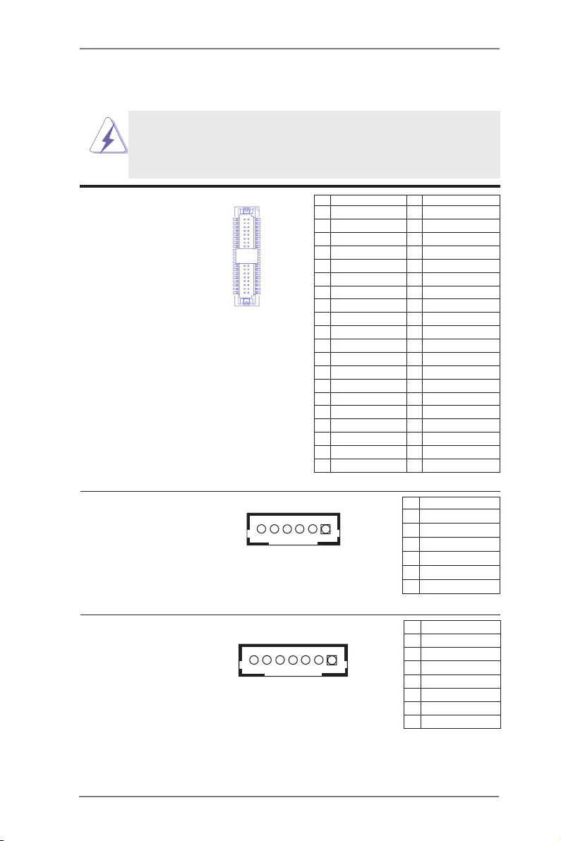
2.6 Onboard Headers and Connectors
Onboard headers and connectors are NOT jumpers. Do NOT place
jumper caps over these headers and connectors. Placing jumper caps
over the headers and connectors will cause permanent damage of the
motherboard!
LVDS Panel Connector
(40-pin LVDS1)
(see p.14, No. 3)
40
39
1
2
PIN Signal Name PIN Signal Name
2 R_LVDD 1 R_LVDD
4 LDDC_CLK 3 +3V
6 LVDS_A_DATA0# 5 LDDC_DATA
8 GND 7 LVDS_A_DATA0
10 LVDS_A_DATA1 9 LVDS_A_DATA1#
12 LVDS_A_DATA2# 11 GND
14 GND 13 LVDS_A_DATA2
16 LVDS_A_DATA3 15 LVDS_A_DATA3#
18 LVDS_A_CLK# 17 GND
20 GND 19 LVDS_A_CLK
22 LVDS_B_DATA0 21 LVDS_B_DATA0#
24 LVDS_B_DATA1# 23 GND
26 GND 25 LVDS_B_DATA1
28 LVDS_B_DATA2 27 LVDS_B_DATA2#
30 LVDS_B_DATA3# 29 DPLVDD_EN
32 GND 31 LVDS_B_DATA3
34 LVDS_B_CLK 33 LVDS_B_CLK#
36 CON_LBKLT_EN_R 35 GND
38 LCD_BLT_VCC 37 CON_LBKLT_CTL_R
40 LCD_BLT_VCC 39 LCD_BLT_VCC
Inverter Power Control Wafer
(6-pin BLT_PWR1)
(see p.14, No. 8)
PIN Signal Name
1 GND
1
2 GND
3 CON_LBKLT_CTL
4 CON_LBKLT_EN
5 LCD_BLT_VCC
6 LCD_BLT_VCC
Backlight & Amp Volume Control
(7-pin BLT_VOL1)
(see p.14, No. 7)
24
PIN Signal Name
1 GPIO_VOL_UP
1
2 GPIO_VOL_DW
3 PWRDN
4 GPIO_BLT_UP
5 GPIO_BLT_DW
6 GND
7 GND
Page 25
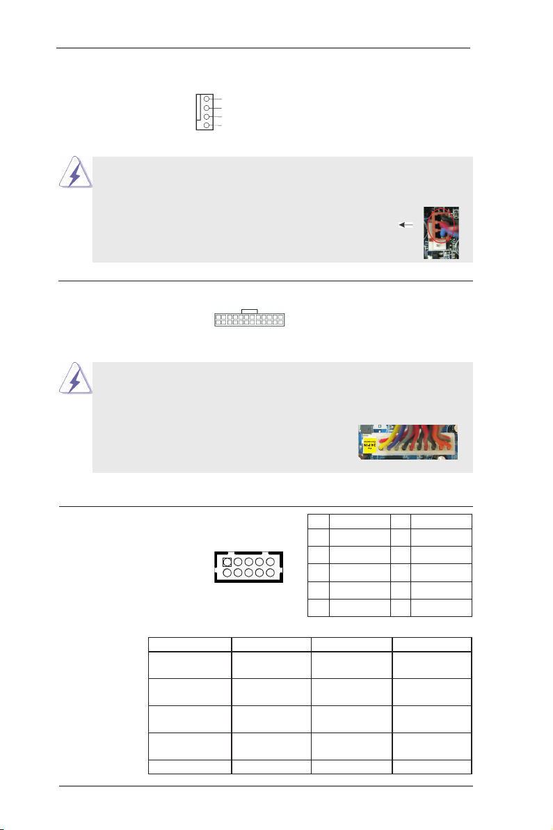
CPU Fan Connector Please connect the CPU fan
1
(4-pin CPU_FAN1)
(see p.14 No. 13)
cable to the connector and
match the black wire to the
ground pin.
Though this motherboard provides 4-Pin CPU fan (Quiet Fan) support, the 3-Pin
CPU fan still can work successfully even without the fan speed control function.
If you plan to connect the 3-Pin CPU fan to the CPU fan connector on this
motherboard, please connect it to Pin 1-3.
2
3
4
GND
+12 V
CPU _FA N_S PEE D
FAN_ SP EED _CO NT ROL
Pin 1-3 Connected
3-Pin Fan Installation
ATX Power Input Connector Please connect an ATX power
(24-pin ATXPWR1)
(see p.14 No. 6)
supply to this connector.
24 13
12 1
Though this motherboard provides 24-pin ATX power connector, it can still work if
you adopt a traditional 20-pin ATX power supply. To use the 20-pin ATX power
supply, please plug your power supply along with Pin 1 and Pin 13.
24 13
20-Pin ATX Power Supply Installation
COM Port Headers
(10-pin COM3: see p.14, No. 9)
(10-pin COM4: see p.14, No. 10)
(10-pin COM5: see p.14, No. 11)
(10-pin COM6: see p.14, No. 12)
1
2
12 1
PIN Signal Name PIN Signal Name
2 RRXD1 1 DDCD#1
4 DDTR#1 3 TTXD1
6 DDSR#1 5 GND
8 CCTS#1 7 RRTS#1
10 NC 9 COM PWR
PIN RS232 RS422 RS485
1
2
3
4
DCD, Data
carrier detect
RXD, Receive
data
TXD, Transmit
data
DTR, Data
terminal ready
TX- RTX-
RX+ N/A
TX+ RTX+
RX- N/A
5 GND GND GND
25
Page 26
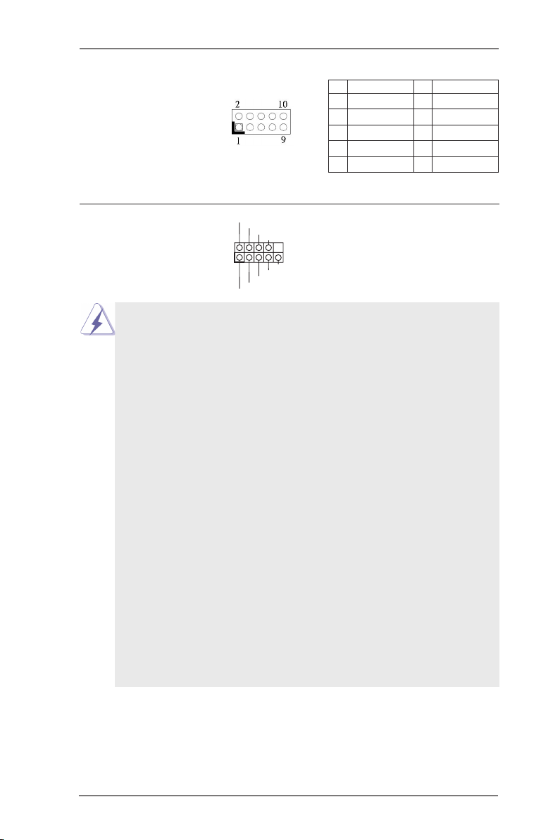
Digital Input / Output Pin Header
(9-pin JGPIO1)
(see p.14, No. 25)
PIN Signal Name PIN Signal Name
1 SIO_GP24 2 SIO_GP20
3 SIO_GP25 4 SIO_GP21
5 SIO_GP26 6 SIO_GP22
7 SIO_GP27 8 SIO_GP23
9 JGPIO_PWR1 10 GND
1
PLED +
PLED -
HDLE D-
HDLE D+
PWRB TN#
GND
RESE T#
GND
DUMM Y
System Panel Header This header accommodates
(9-pin PANEL1)
(see p.14, No. 23)
several system front panel
functions.
Connect the power switch, reset switch and system status indicator on the
chassis to this header according to the pin assignments below. Note the
positive and negative pins before connecting the cables.
PWRBTN (Power Switch):
Connect to the power switch on the chassis front panel. You may congure
the way to turn off your system using the power switch.
RESET (Reset Switch):
Connect to the reset switch on the chassis front panel. Press the reset
switch to restart the computer if the computer freezes and fails to perform a
normal restart.
PLED (System Power LED):
Connect to the power status indicator on the chassis front panel. The LED
is on when the system is operating. The LED keeps blinking when the sys-
tem is in S1/S3 sleep state. The LED is off when the system is in S4 sleep
state or powered off (S5).
HDLED (Hard Drive Activity LED):
Connect to the hard drive activity LED on the chassis front panel. The LED
is on when the hard drive is reading or writing data.
The front panel design may differ by chassis. A front panel module mainly
consists of power switch, reset switch, power LED, hard drive activity LED,
speaker and etc. When connecting your chassis front panel module to this
header, make sure the wire assignments and the pin assign-ments are
matched correctly.
26
Page 27
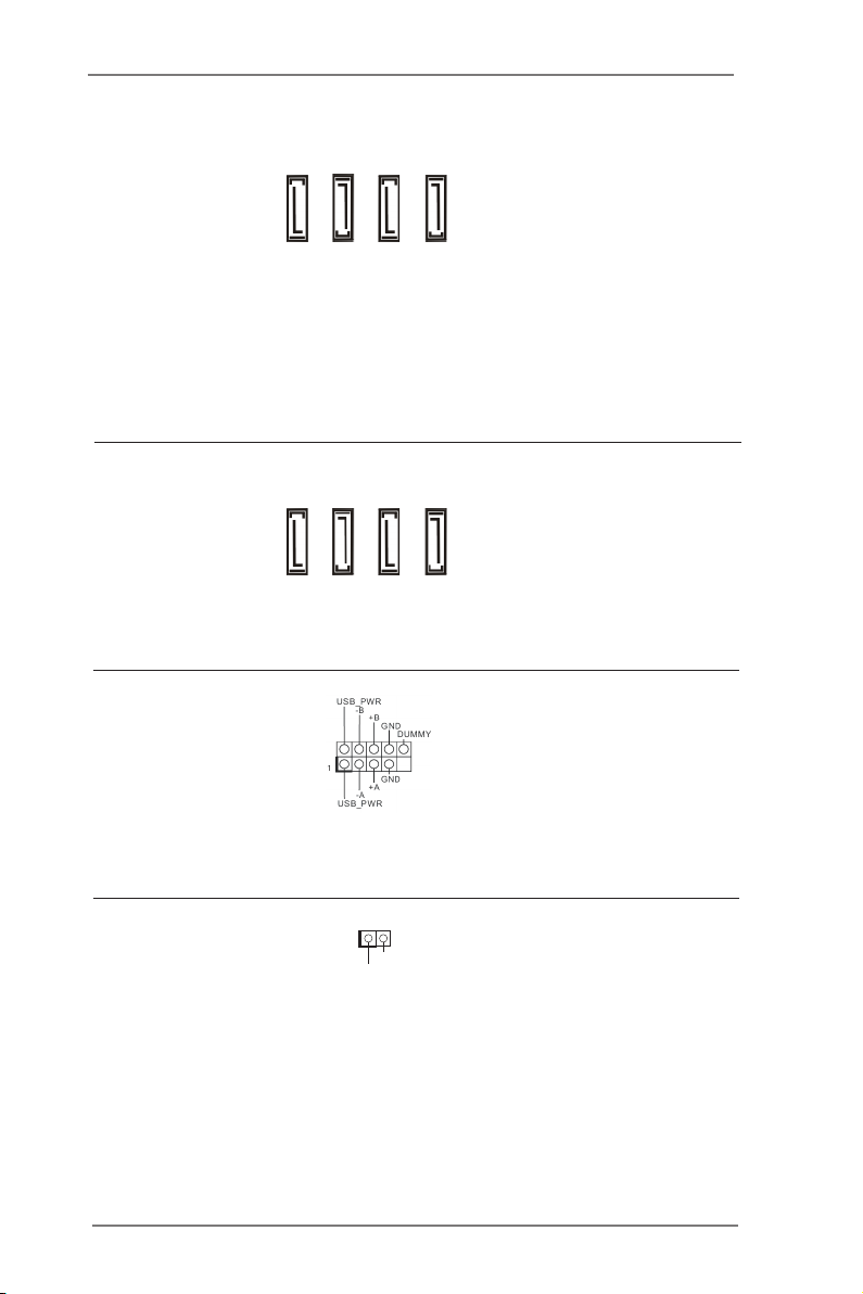
IMB-171-D / IMB-171-L:
SATA2 / SATA3 Connectors These two Serial ATA3 (SATA3)
(SATA_0: see p.14, No. 17)
SATA_1
SATA_0
connectors and two Serial ATA2
SATA_2
SATA_3
(SATA2) connectors support
SATA data cables for internal
storage devices. The current
SATA3 interface allows up to
6.0 Gb/s data transfer rate, and
the current SATA2 interface
allows up to 3.0 Gb/s data
transfer rate .
IMB-161-D / IMB-161-L:
SATA2 Connectors These four Serial ATA2
(SATA_0: see p.14, No. 17)
(SATA_1: see p.14, No. 18)
(SATA_2: see p.14, No. 19)
(SATA_3: see p.14, No. 20)
SATA_1
SATA_0
(SATA2) connectors support
SATA data cables for internal
storage devices. The current
SATA2 interface allows up to
SATA_2
SATA_3
3.0 Gb/s data transfer rate.
USB 2.0 Headers Besides the default USB 2.0
(9-pin USB6_7: see p.14, No. 2)
(9-pin USB8_9: see p.14, No. 1)
ports on the I/O panel, there are
two USB 2.0 headers and one
USB 2.0 port on this
motherboard. Each USB 2.0
header can support two USB 2.0
ports.
Chassis Intrusion Header This motherboard supports
(2-pin CI1: see p.14, No. 15)
(2-pin CI2: see p.14, No. 14)
CASE OPEN detection feature
that detects if the chassis cover
1
Sig n al
GND
has been removed. This feature
requires a chassis with chassis
intrusion detection design.
27
Page 28
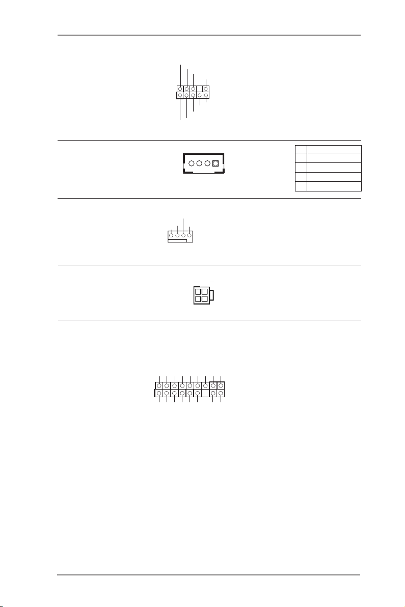
1
Front Panel Audio Header This is an interface for front
(9-pin HD_AUDIO1)
(see p.14 No. 33)
panel audio cable that allows
convenient connection and
control of audio devices.
1
GND
PRE SEN CE#
MIC 2_R
MIC 2_L
MIC _RE T
J_S ENS E
OUT 2_R
OUT _RE T
OUT 2_L
3W Audio Amp Output Wafer
(4-pin SPEAKER1)
(see p.14, No. 24)
1
Chassis Fan Connector Please connect the fan cable
(4-pin CHA_FAN1)
(see p.14, No. 27)
to the fan connector and
match the black wire to the
CHA _FA N_S PEE D
+12 V
FAN _SP EED _CO NTR OL
GND
PIN Signal Name
1 SPK L-
2 SPK L+
3 SPK R+
4 SPK R-
ground pin.
ATX 12V Power Input Connector Please connect an ATX 12V
(4-pin ATX12V1)
(see p.14, No. 21)
TPM Header This connector supports a
(17-pin TPM1)
see p.14, No. 22)
(
securely store keys, digital
power supply to this connector.
SMB _DA TA_ MAI N
Trusted Platform Module (TPM)
system, which can
SMB _CL K_M AIN
GND
S_P WRD WN#
LAD 2
SER IRQ #
LAD 1
GND
GND
certicates, passwords, and
data. A TPM system also helps
LAD 3
PCI RST #
FRA ME
enhance network security,
PCI CLK
LAD 0
GND
+3V SB
+3V
protects digital identities, and
ensures platform integrity.
28
Page 29
2.7 Serial ATA2 (SATA2) / Serial ATA3 (SATA3) Hard Disks Installation
IMB-171-D / IMB-171-L adopts Intel® Q77 chipset that supports Serial ATA2 (SATA2)
/ Serial ATA3 (SATA3) hard disks and RAID (RAID 0, RAID 1, RAID 5 and RAID 10)
functions. IMB-161-D / IMB-161-L adopts Intel® H61 chipset that supports Serial
ATA2 (SATA2) hard disks. You may install SATA2 / SATA3 hard disks on this moth-
erboard for internal storage devices. This section will guide you to install the SATA2
/ SATA3 hard disks.
STEP 1: Install the SATA2 / SATA3 hard disks into the drive bays of your chassis.
STEP 2: Connect the SATA power cable to the SATA2 / SATA3 hard disk.
STEP 3: Connect one end of the SATA data cable to the motherboard’s SATA2 /
SATA3 connector.
STEP 4: Connect the other end of the SATA data cable to the SATA2 / SATA3 hard
disk.
2.8 Hot Plug and Hot Swap Functions for SATA2 / SATA3 HDDs
IMB-171-D / IMB-171-L supports Hot Plug for SATA2 / SATA3 in RAID / AHCI
mode. IMB-161-D / IMB-161-L supports Hot Plug for SATA2 in AHCI mode. Intel®
Q77 / H61 chipset provides hardware support for Advanced Host controller Interface
(AHCI), a new programming interface for SATA host controllers developed through a
joint industry effort.
NOTE
What is Hot Plug Function?
If the SATA2 / SATA3 HDDs are NOT set for RAID conguration, it is called
“Hot Plug” for the action to insert and remove the SATA2 / SATA3 HDDs
while the system is still power-on and in working condition.
However, please note that it cannot perform Hot Plug if the OS has been
installed into the SATA2 / SATA3 HDD.
What is Hot Swap Function?
If SATA2 / SATA3 HDDs are built as RAID 1 or RAID 5 then it is called “Hot
Swap” for the action to insert and remove the SATA2 / SATA3 HDDs while
the system is still power-on and in working condition.
29
Page 30

2.9 Driver Installation Guide
To install the drivers to your system, please insert the support CD to your optical
drive rst. Then, the drivers compatible to your system can be auto-detected and
listed on the support CD driver page. Please follow the order from top to bottom to
install those required drivers. Therefore, the drivers you install can work properly.
30
Page 31
Chapter 3: UEFI SETUP UTILITY
3.1 Introduction
This section explains how to use the UEFI SETUP UTILITY to congure your
system. The UEFI chip on the motherboard stores the UEFI SETUP UTILITY. You
may run the UEFI SETUP UTILITY when you start up the computer. Please press
<F2> or <Del> during the Power-On-Self-Test (POST) to enter the UEFI SETUP
UTILITY, otherwise, POST will continue with its test routines.
If you wish to enter the UEFI SETUP UTILITY after POST, restart the system by
pressing <Ctl> + <Alt> + <Delete>, or by pressing the reset button on the system
chassis. You may also restart by turning the system off and then back on.
Because the UEFI software is constantly being updated, the
following UEFI setup screens and descriptions are for reference
purpose only, and they may not exactly match what you see on
your screen.
3.1.1 UEFI Menu Bar
The top of the screen has a menu bar with the following selections:
Main To set up the system time/date information
Advanced To set up the advanced UEFI features
H/W Monitor To display current hardware status
Boot To set up the default system device to locate and load the
Operating System
Security To set up the security features
Exit To exit the current screen or the UEFI SETUP UTILITY
Use < > key or < > key to choose among the selections on the menu
bar, and then press <Enter> to get into the sub screen. You can also use the
mouse to click your required item.
31
Page 32
3.1.2 Navigation Keys
Please check the following table for the function description of each navigation
key.
Navigation Key(s) Function Description
/ Moves cursor left or right to select Screens
/ Moves cursor up or down to select items
+ / - To change option for the selected items
<Enter> To bring up the selected screen
<F1> To display the General Help Screen
<F7> Discard changes
<F9> To load optimal default values for all the settings
<F10> To save changes and exit the UEFI SETUP UTILITY
<F12> Print screen
<ESC> To jump to the Exit Screen or exit the current screen
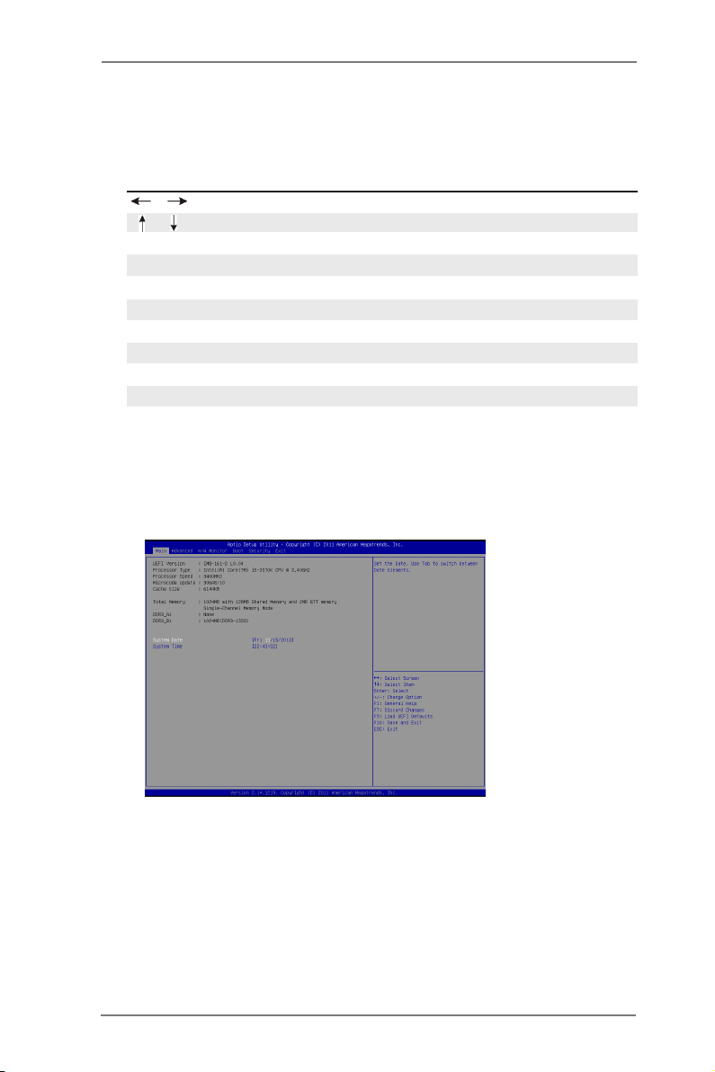
3.2 Main Screen
When you enter the UEFI SETUP UTILITY, the Main screen will appear and display
the system overview.
32
Page 33
3.3 Advanced Screen
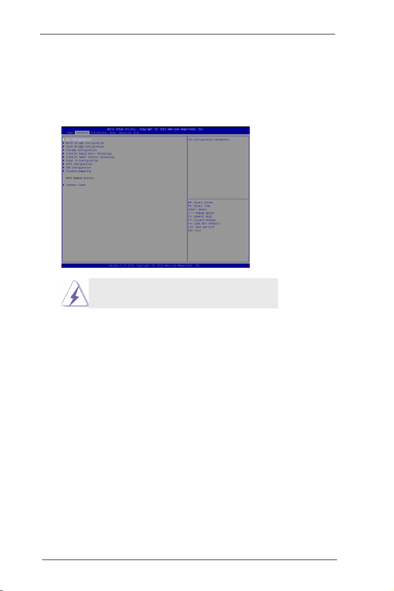
In this section, you may set the congurations for the following items: CPU Congu-
ration, Northbridge Conguration, Southbridge Conguration, Storage Conguration,
Intel(R) Rapid Start Technology, Intel(R) Smart Connect Technology, Super IO Con-
guration, ACPI Conguration, USB Conguration and Trusted Computing.
Setting wrong values in this section may cause
the system to malfunction.
Instant Flash
Instant Flash is a UEFI ash utility embedded in Flash ROM. This conve-
nient UEFI update tool allows you to update system UEFI without entering
operating systems rst like MS-DOS or Windows®. Just launch this tool
and save the new UEFI le to your USB ash drive, oppy disk or hard
drive, then you can update your UEFI only in a few clicks without prepar-
ing an additional oppy diskette or other complicated ash utility. Please
be noted that the USB ash drive or hard drive must use FAT32/16/12 le
system. If you execute Instant Flash utility, the utility will show the UEFI
les and their respective information. Select the proper UEFI le to update
your UEFI, and reboot your system after UEFI update process completes.
33
Page 34
3.3.1 CPU Configuration
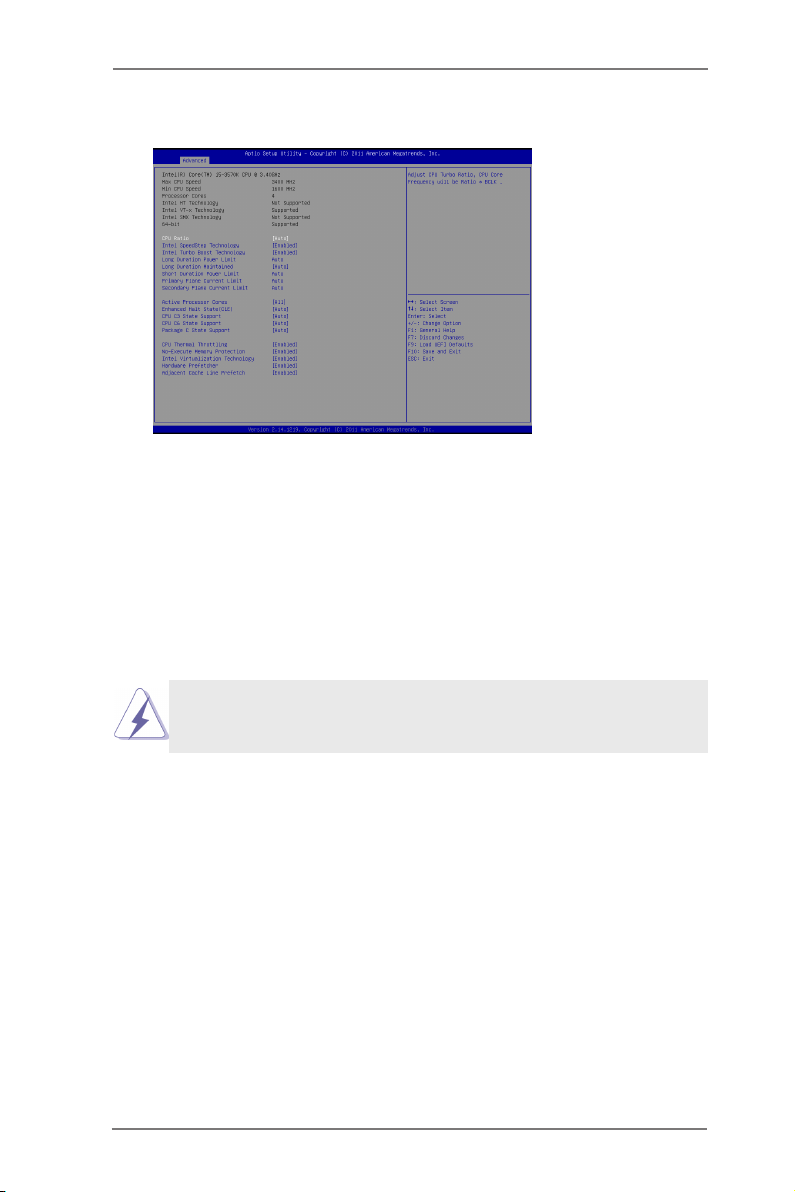
CPU Ratio
Use this item to change the ratio value of this motherboard.
Intel SpeedStep Technology
Intel SpeedStep technology is Intel’s new power saving technology. Pro-
cessors can switch between multiple frequencies and voltage points to en-
able power saving. The default value is [Enabled]. Conguration options:
[Enabled] and [Disabled]. If you install Windows® VistaTM / 7 / 8 and want
to enable this function, please set this item to [Enabled]. This item will be
hidden if the current CPU does not support Intel SpeedStep technology.
Please note that enabling this function may reduce CPU voltage and lead to system
stability or compatibility issues with some power supplies. Please set this item to
[Disabled] if above issues occur.
Intel Turbo Boost Technology
Use this item to enable or disable Intel Turbo Boost Mode Technology.
Turbo Boost Mode allows processor cores to run faster than marked fre-
quency in specic conditions. The default value is [Enabled].
Long Duration Power Limit
Use this item to congure long duration power limit in watts. The default
value is [Auto].
Long Duration Maintained
Use this item to congure time window which the long duration power is
maintained. The default value is [Auto].
Short Duration Power Limit
Use this item to congure short duration power limit in watts. The default
value is [Auto].
34
Page 35

Primary Plane Current Limit
Use this item to congure the maximum instantaneous current allowed for
the primary plane. The default value is [Auto].
Secondary Plane Current Limit
Use this item to congure the maximum instantaneous current allowed for
the secondary plane. The default value is [Auto].
Intel Hyper Threading Technology
To enable this feature, a computer system with an Intel processor that sup-
ports Hyper-Threading technology and an operating system that includes
optimization for this technology, such as Microsoft® Windows® XP / VistaTM /
7 / 8 is required. Set to [Enabled] if using Microsoft® Windows® XP, VistaTM,
7, 8, or Linux kernel version 2.4.18 or higher. This option will be hidden if
the installed CPU does not support Hyper-Threading technology.
Active Processor Cores
Use this item to select the number of cores to enable in each processor
package. The default value is [All].
Enhance Halt State (C1E)
All processors support the Halt State (C1). The C1 state is supported
through the native processor instructions HLT and MWAIT and requires no
hardware support from the chipset. In the C1 power state, the processor
maintains the context of the system caches.
CPU C3 State Support
Use this to enable or disable CPU C3 (ACPI C2) report to OS.
CPU C6 State Support
Use this to enable or disable CPU C6 (ACPI C3) report to OS.
Package C State Support
Selected option will program into C State package limit register. The
default value is [Auto].
CPU Thermal Throttling
You may select [Enabled] to enable CPU internal thermal control
mechanism to keep the CPU from overheating.
No-Execute Memory Protection
No-Execution (NX) Memory Protection Technology is an enhancement
to the IA-32 Intel Architecture. An IA-32 processor with “No Execute (NX)
Memory Protection” can prevent data pages from being used by malicious
software to execute codes. This option will be hidden if the current CPU
does not support No-Excute Memory Protection.
35
Page 36

Intel Virtualization Technology
When this option is set to [Enabled], a VMM (Virtual Machine Architecture)
can utilize the additional hardware capabilities provided by Vanderpool
Technology. This option will be hidden if the installed CPU does not
support Intel Virtualization Technology.
Hardware Prefetcher
Use this item to turn on/off the MLC streamer prefetcher.
Adjacent Cache Line Prefetch
Use this item to turn on/off prefetching of adjacent cache lines.
36
Page 37
3.3.2 North Bridge Configuration
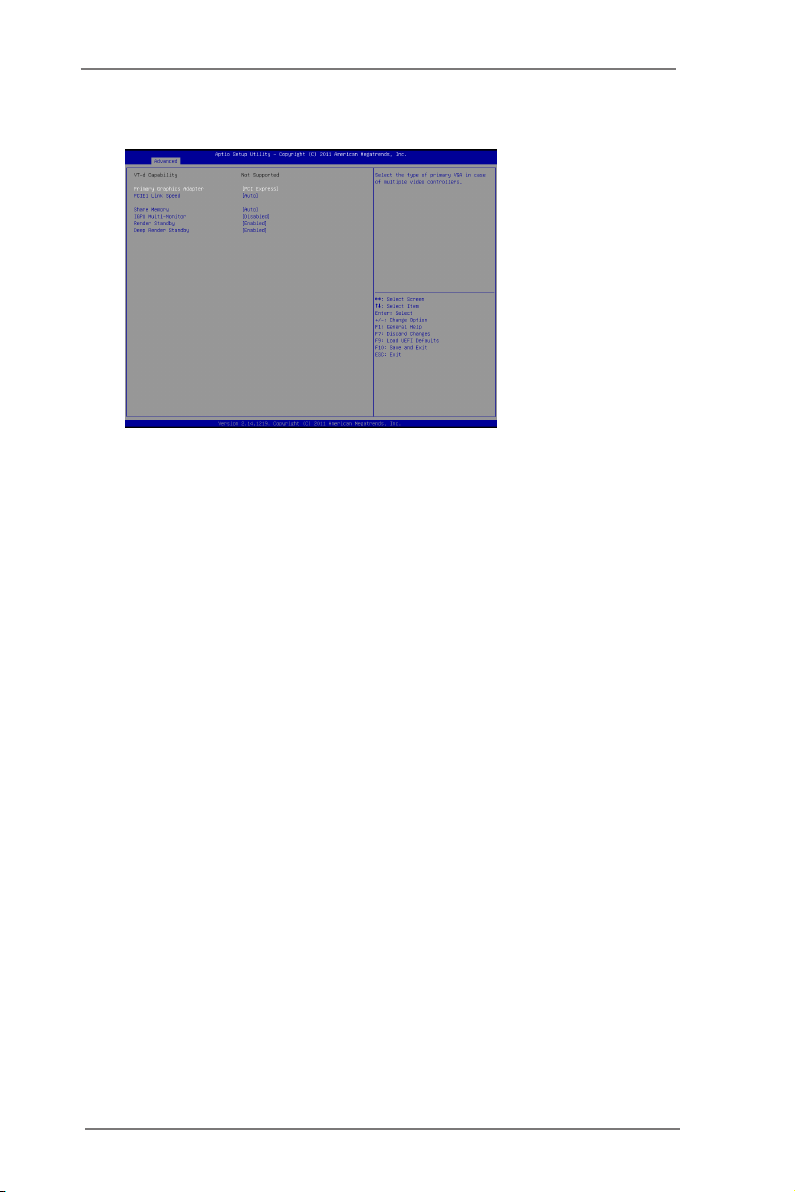
PCIE1 Link Speed
This allows you to select PCIE 1 Link Speed. The default value is [Auto].
Share Memory
This allows you to set onboard VGA share memory feature. The default
value is [Auto].
IGPU Multi-Monitor
This allows you to enable or disable IGPU Multi-Monitor. The default value
is [Disabled]. If you wish to install a PCI Express card under Windows® XP
/ VistaTM OS, please disable this option.
Render Standby
Use this to enable or disable Render Standby by Internal Graphics Device.
The default value is [Enabled].
Deep Render Standby
This allows you to enable or disable Deep Render Standby. The default
value is [Enabled].
37
Page 38
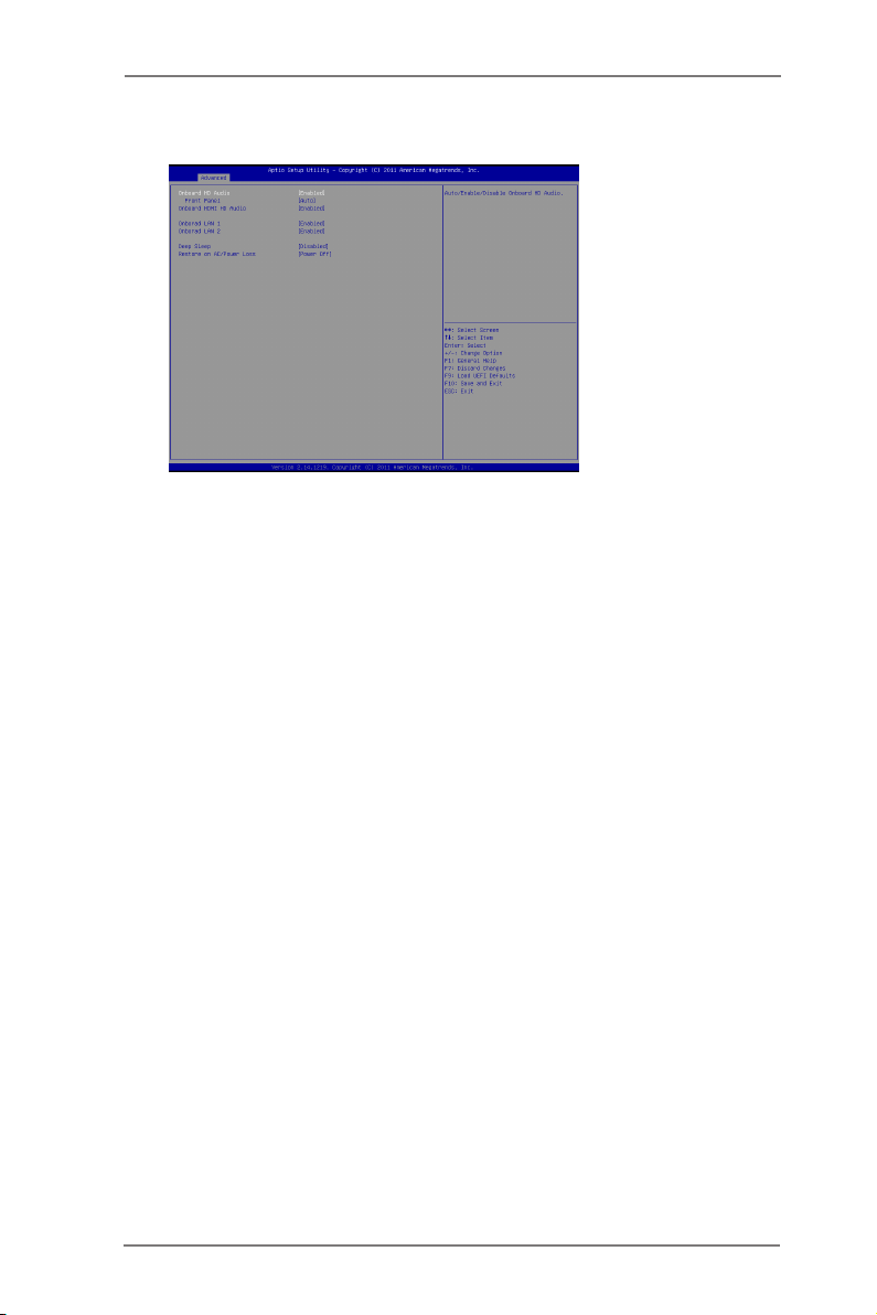
3.3.3 South Bridge Configuration
Onboard HD Audio
Select [Auto], [Enabled] or [Disabled] for the onboard HD Audio feature. If
you select [Auto], the onboard HD Audio will be disabled when PCI Sound
Card is plugged.
Front Panel
Select [Auto] or [Disabled] for the onboard HD Audio Front Panel.
Onboard HDMI HD Audio
This allows you to enable or disable the Onboard HDMI HD Audio feature.
Onboard LAN 1
This allows you to enable or disable the Onboard LAN 1 feature.
Onboard LAN 2
This allows you to enable or disable the Onboard LAN 2 feature.
Deep Sleep
Mobile platforms support Deep S4/S5 in DC only and desktop platforms
support Deep S4/S5 in AC only. The default value is [Disabled].
Restore on AC/Power Loss
This allows you to set the power state after an unexpected AC/power loss.
If [Power Off] is selected, the AC/power remains off when the power
recovers. If [Power On] is selected, the AC/power resumes and the
system starts to boot up when the power recovers.
38
Page 39
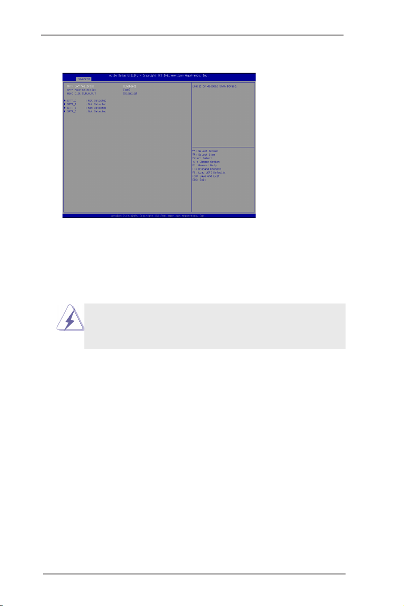
3.3.4 Storage Configuration
SATA Controller(s)
Use this item to enable or disable the SATA Controller feature.
SATA Mode Selection
Use this to select SATA mode. Conguration options: [IDE Mode], [AHCI
Mode] and [RAID Mode]. The default value is [IDE Mode].
* IMB-161-D / IMB-161-L does not support RAID mode.
AHCI (Advanced Host Controller Interface) supports NCQ
and other new features that will improve SATA disk perfor-
mance but IDE mode does not have these advantages.
Hard Disk S.M.A.R.T.
Use this item to enable or disable the S.M.A.R.T. (Self-Monitoring, Analy-
sis, and Reporting Technology) feature. Conguration options: [Disabled]
and [Enabled].
39
Page 40
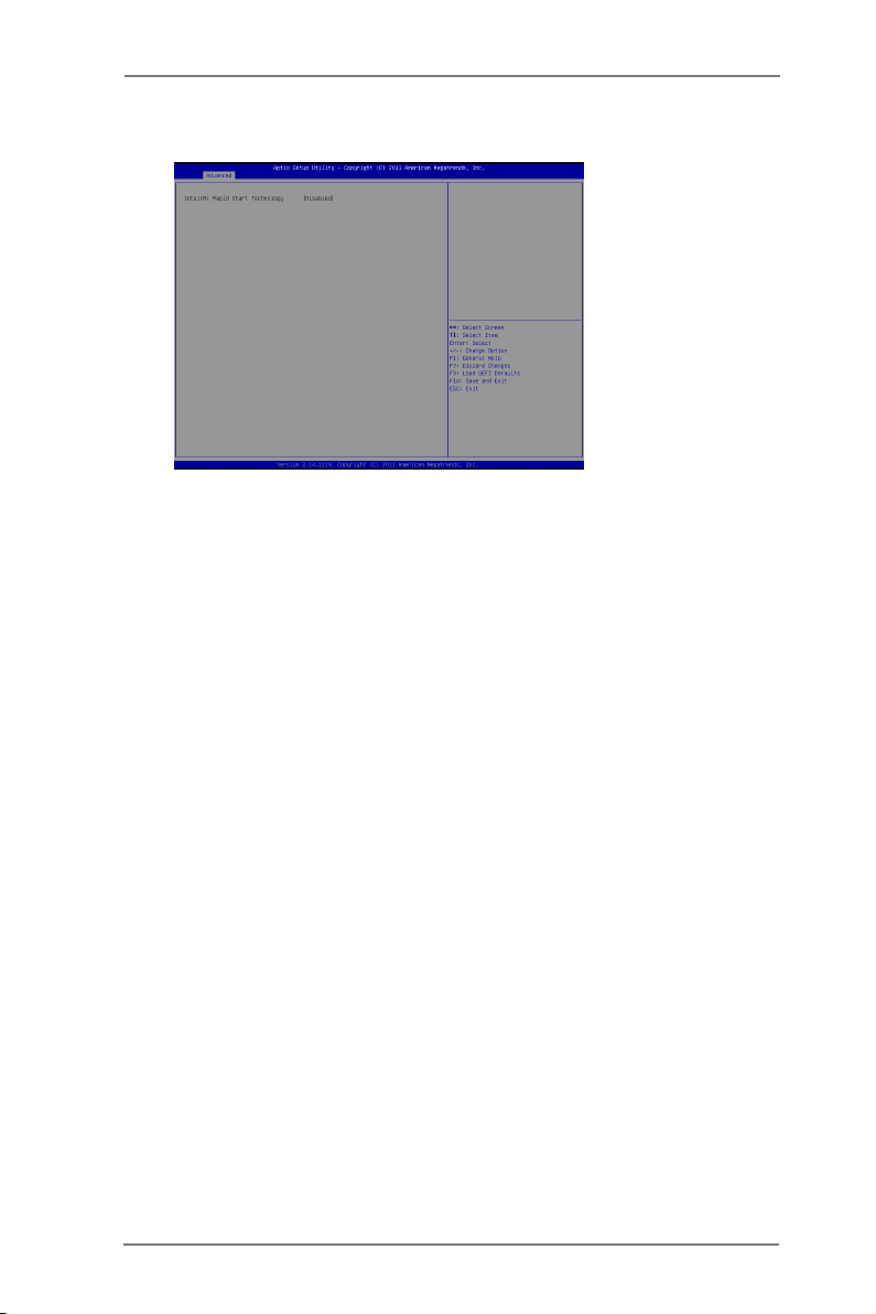
3.3.5 Intel(R) Rapid Start Technology
Intel(R) Rapid Start Technology
Use this item to enable or disable Intel(R) Rapid Start Technology. Intel(R)
Rapid Start Technology is a new zero power hibernation mode which al-
lows users to resume in just 5-6 seconds. The default is [Disabled].
40
Page 41
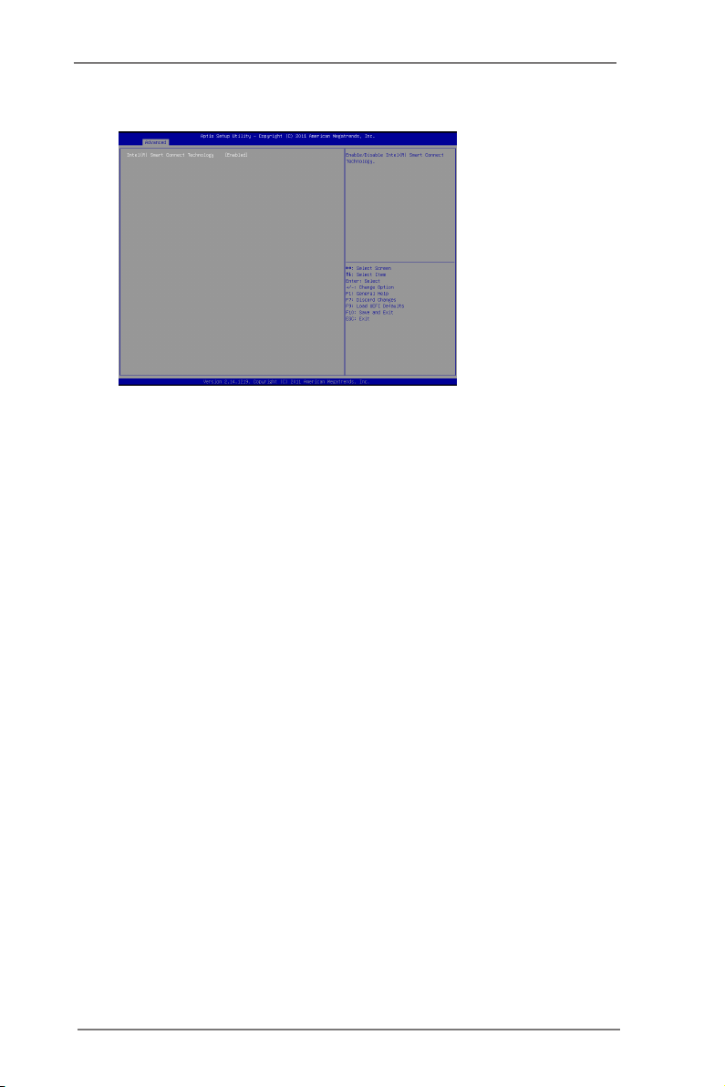
3.3.6 Intel(R) Smart Connect Technology
Intel(R) Smart Connect Technology
Use this item to enable or disable Intel(R) Smart Connect Technology.
Intel(R) Smart Connect Technology keeps your e-mail and social networks,
such as Twitter, Facebook, etc. updated automatically while the computer
is in sleep mode. The default is [Enabled].
41
Page 42
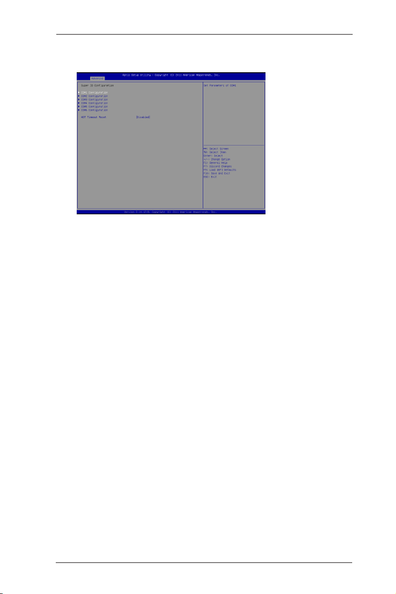
3.3.7 Super IO Configuration
COM1 Conguration
Use this to set parameters of COM1.
COM2 Conguration
Use this to set parameters of COM2.
COM3 Conguration
Use this to set parameters of COM3.
COM4 Conguration
Use this to set parameters of COM4.
COM5 Conguration
Use this to set parameters of COM5.
COM6 Conguration
Use this to set parameters of COM6.
WDT Timeout Reset
This allows users to enable/disable the Watch Dog Timer timeout to reset
system. The default value is [Disabled].
42
Page 43
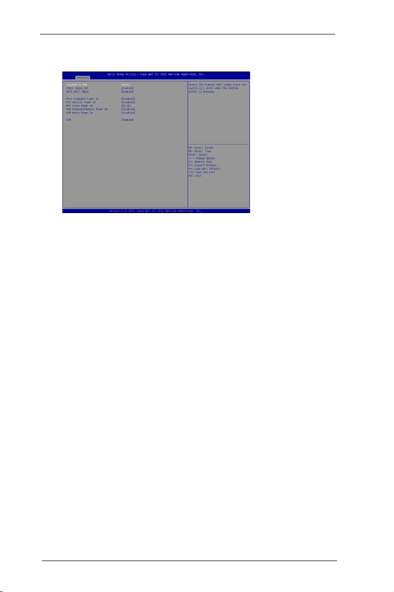
3.3.8 ACPI Configuration
Suspend to RAM
Use this item to select whether to auto-detect or disable the Suspend-to-
RAM feature. Select [Auto] will enable this feature if the OS supports it.
Check Ready Bit
Use this item to enable or disable the feature Check Ready Bit.
ACPI HPET Table
Use this item to enable or disable ACPI HPET Table. The default value is
[Enabled]. Please set this option to [Enabled] if you plan to use this
motherboard to submit Windows® certication.
PS/2 Keyboard Power On
Use this item to enable or disable PS/2 keyboard to turn on the system
from the power-soft-off mode.
PCI Devices Power On
Use this item to enable or disable PCI devices to turn on the system from
the power-soft-off mode.
RTC Alarm Power On
Use this item to enable or disable RTC (Real Time Clock) to power on the
system.
USB Keyboard/Remote Power On
Use this item to enable or disable USB Keyboard/Remote to power on the
system.
USB Mouse Power On
Use this item to enable or disable USB Mouse to power on the system.
CSM
Please disable CSM when you enable Fast Boot option. The default value
is [Enabled].
43
Page 44
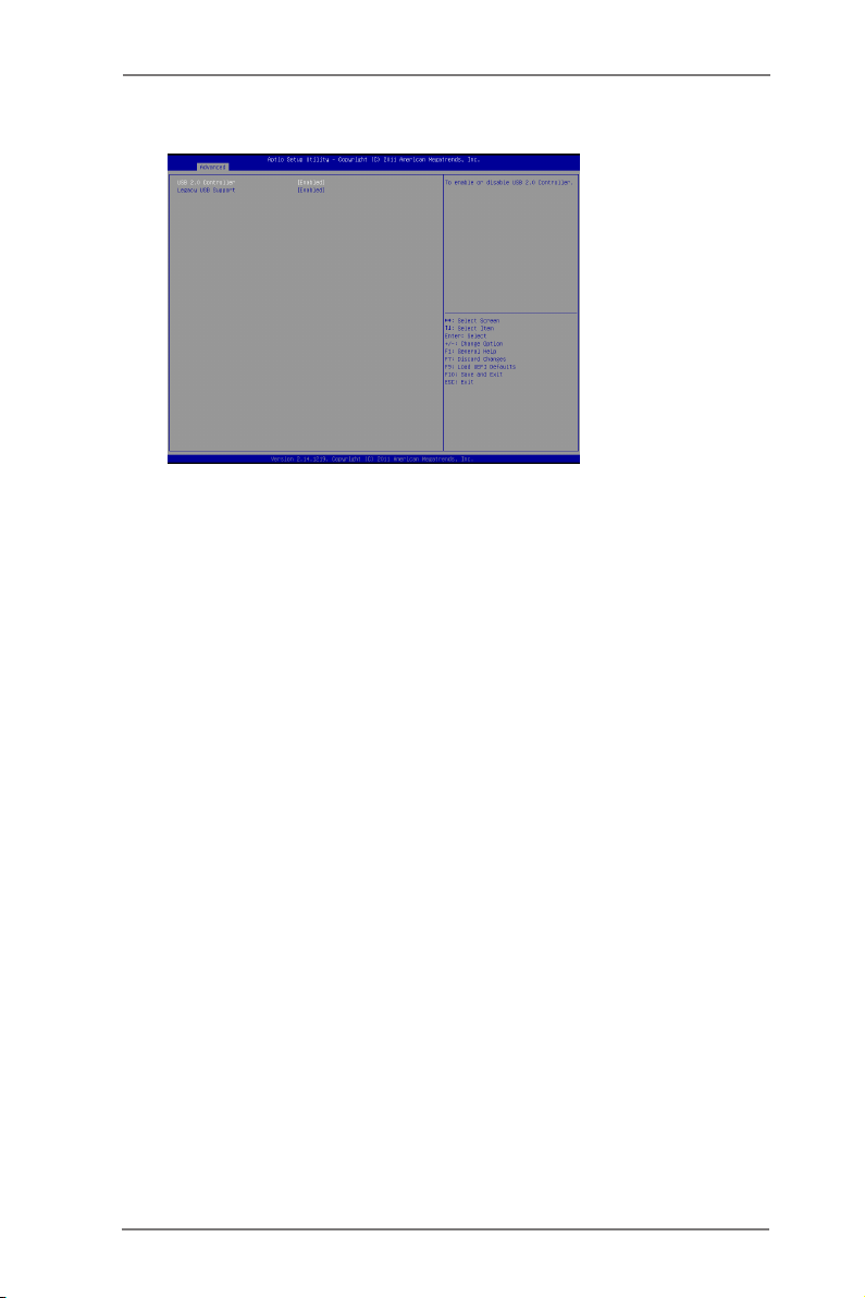
3.3.9 USB Configuration
USB 2.0 Controller
Use this item to enable or disable the use of USB 2.0 controller.
USB 3.0 Controller
Use this item to enable or disable the use of USB 3.0 controller.
Legacy USB Support
Use this option to select legacy support for USB devices. There are four
conguration options: [Enabled], [Auto], [Disabled] and [UEFI Setup Only].
The default value is [Enabled]. Please refer to below descriptions for the
details of these four options:
[Enabled] - Enables support for legacy USB.
[Auto] - Enables legacy support if USB devices are connected.
[Disabled] - USB devices are not allowed to use under legacy OS and
UEFI setup when [Disabled] is selected. If you have USB compatibility is-
sues, it is recommended to select [Disabled] to enter OS.
[UEFI Setup Only] - USB devices are allowed to use only under UEFI
setup and Windows / Linux OS.
Legacy USB 3.0 Support
Use this option to enable or disable legacy support for USB 3.0 devices.
The default value is [Enabled].
* USB 3.0 is supported by IMB-171-D / IMB-171-L only.
44
Page 45
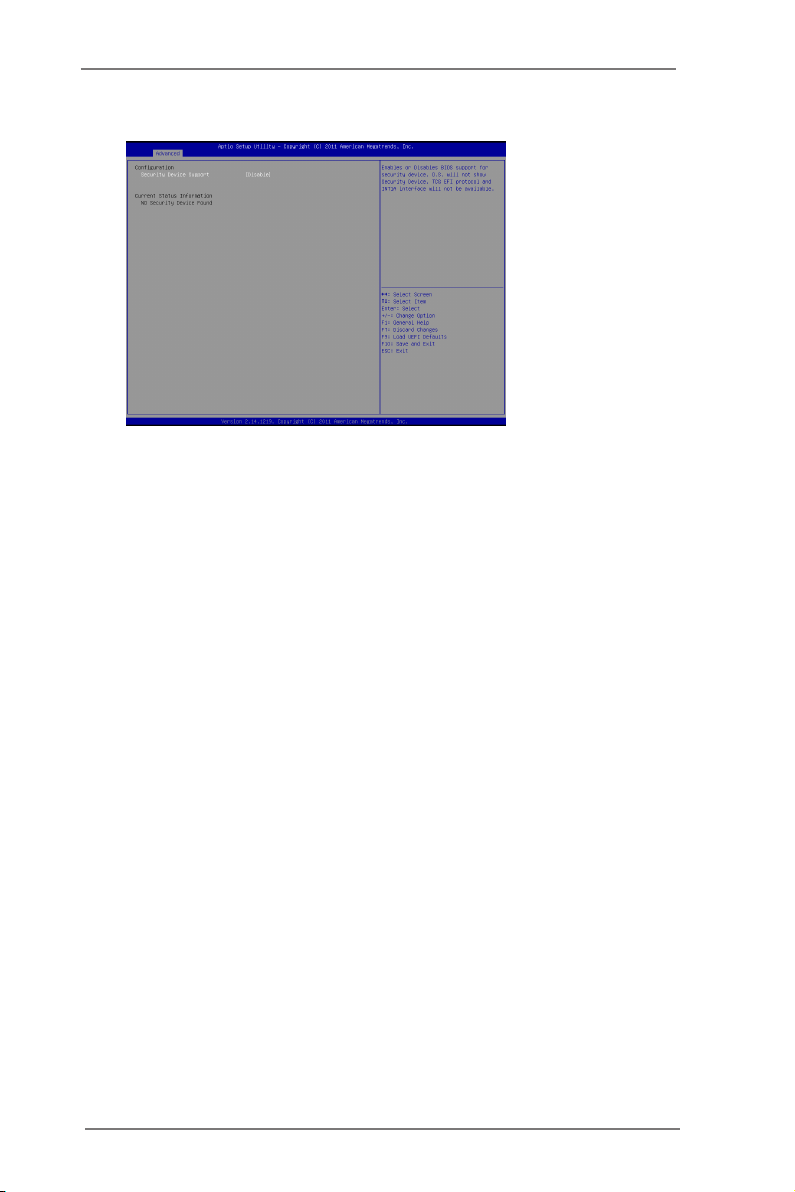
3.3.10 Trusted Computing
Conguration
Security Device Support
Use this item to enable or disable BIOS support for security device. OS
will not show security device. TCG EFI protocol and INT1A interface will
not be available.
Current Status Information
Use this item to see TPM current status information, such as TPM
enabled status, TPM active status and TPM owner status.
45
Page 46
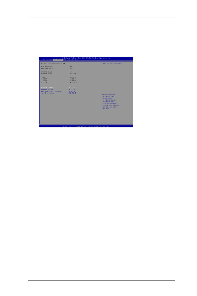
3.4 Hardware Health Event Monitoring Screen
In this section, it allows you to monitor the status of the hardware on your system,
including the parameters of the CPU temperature, motherboard temperature, CPU
fan speed, chassis fan speed, and the critical voltage.
CPU_FAN1 Setting
This allows you to set CPU fan 1’s speed. Conguration options: [Full On]
and [Automatic Mode]. The default value is [Full On].
CHA_FAN1 Setting
This allows you to set chassis fan 1’s speed. Conguration options: [Full
On] and [Automatic Mode]. The default value is [Full On].
Over Temperature Protection
Use this to enable or disable Over Temperature Protection. The default
value is [Enabled].
Case Open Feature
This allows you to enable or disable case open detection feature. The
default is value [Disabled].
Clear Status
This option appears only when the case open has been detected. Use this
option to keep or clear the record of previous chassis intrusion status.
46
Page 47
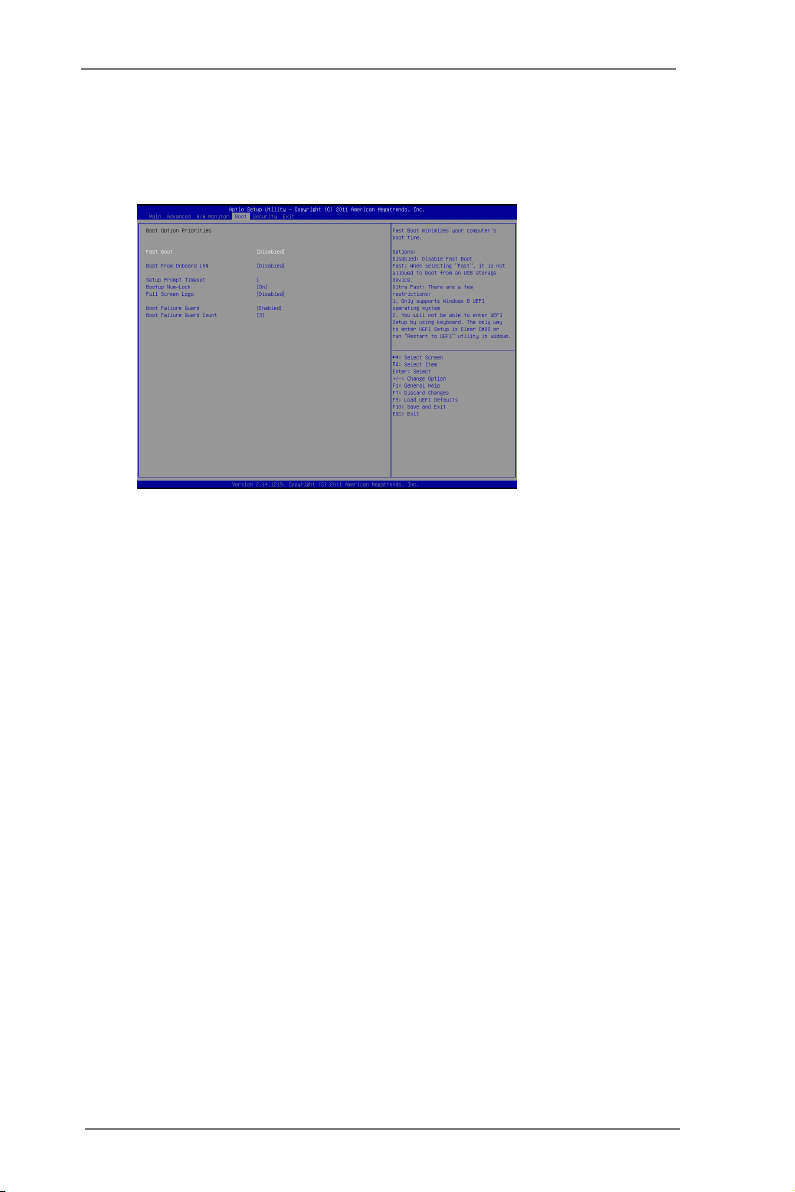
3.5 Boot Screen
In this section, it will display the available devices on your system for you to cong-
ure the boot settings and the boot priority.
Fast Boot
Fast Boot minimizes your computer’s boot time. There are three con-
guration options: [Disabled], [Fast] and [Ultra Fast]. The default value is
[Disabled]. Please refer to below descriptions for the details of these three
options:
[Disabled] - Disable Fast Boot.
[Fast] - The only restriction is you may not boot by using an USB ash
drive.
[Ultra Fast] - There are a few restrictions.
1. Only supports Windows® 8 UEFI operating system.
2. You will not be able to enter BIOS Setup (Clear CMOS or run utility
in Widows® to enter BIOS Setup).
3. If you are using an external graphics card, the VBIOS must support
UEFI GOP in order to boot.
Boot From Onboard LAN
Use this item to enable or disable the Boot From Onboard LAN feature.
Setup Prompt Timeout
Thi s sho ws the number of seconds to wait for setup activat ion key.
65535(0XFFFF) means indenite waiting.
Bootup Num-Lock
If this item is set to [On], it will automatically activate the Numeric Lock
function after boot-up.
47
Page 48

Full Screen Logo
Use this item to enable or disable OEM Logo. The default value is [En-
abled].
AddOn ROM Display
Use this option to adjust AddOn ROM Display. If you enable the option “Full
Screen Logo” but you want to see the AddOn ROM information when the
system boots, please select [Enabled]. Conguration options: [Enabled]
and [Disabled]. The default value is [Enabled].
Boot Failure Guard
Enable or disable the feature of Boot Failure Guard.
Boot Failure Guard Count
Use this item to congure Boot Failure Guard Count.
48
Page 49
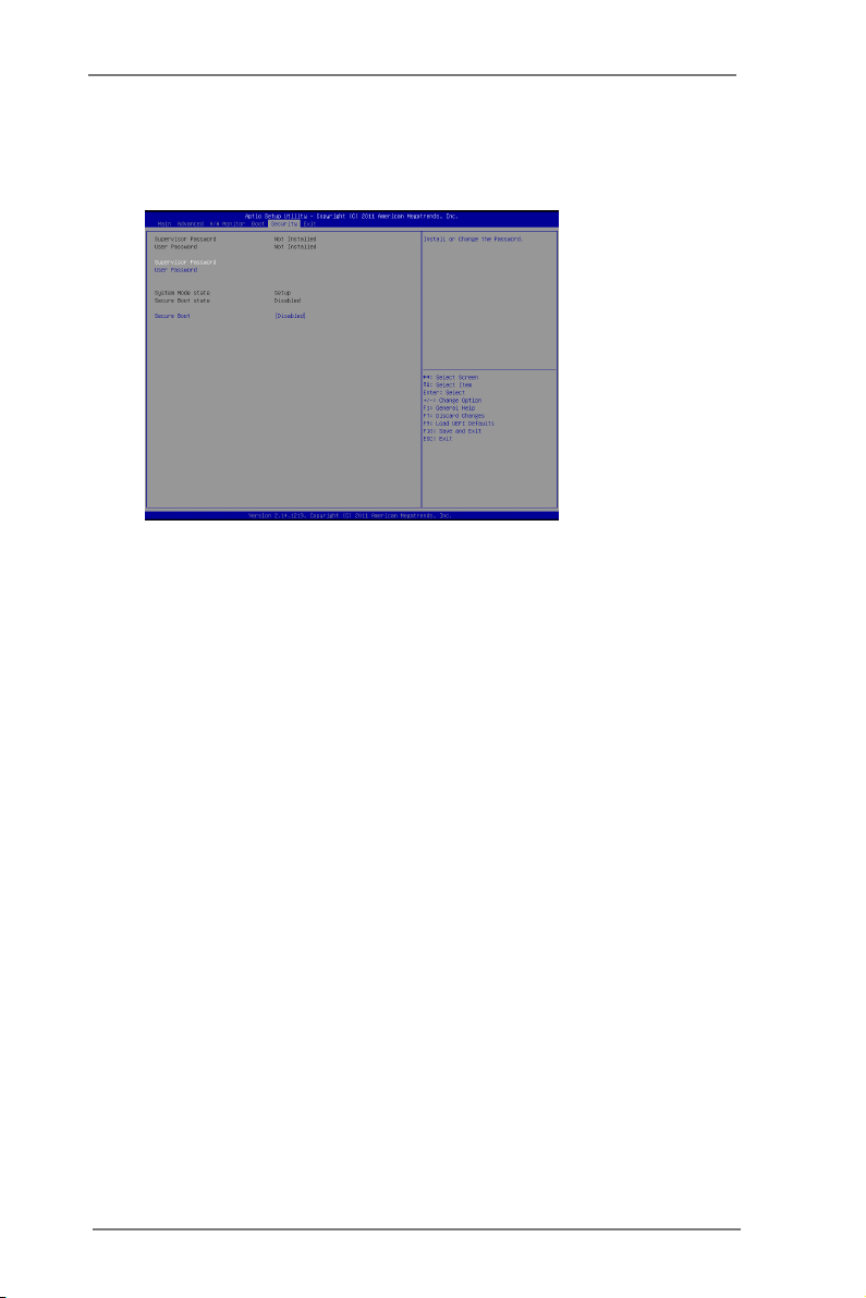
3.6 Security Screen
In this section, you may set, change or clear the supervisor/user password for the
system.
Secure Boot
Use this to enable or disable Secure Boot. The default value is [Disabled].
49
Page 50
3.7 Exit Screen
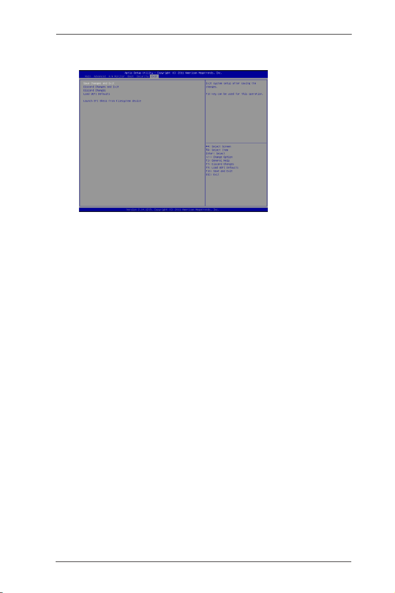
Save Changes and Exit
When you select this option, it will pop-out the following message, “Save
conguration changes and exit setup?” Select [OK] to save the changes
and exit the UEFI SETUP UTILITY.
Discard Changes and Exit
When you select this option, it will pop-out the following message, “Discard
changes and exit setup?” Select [OK] to exit the UEFI SETUP UTILITY
without saving any changes.
Discard Changes
When you select this option, it will pop-out the following message, “Discard
changes?” Select [OK] to discard all changes.
Load UEFI Defaults
Load UEFI default values for all the setup questions. F9 key can be used
for this operation.
Launch EFI Shell from lesystem device
Attempts to Launch EFI Shell application (Shell64.efi) from one of the
available lesystem devices.
50
Page 51

Chapter 4: Software Support
4.1 Install Operating System
This motherboard supports various Microsoft® Windows® operating systems: 8 / 8
64-bit / 7 / 7 64-bit / VistaTM / Vista
settings and hardware options vary, use the setup procedures in this chapter for
general reference only. Refer your OS documentation for more information.
4.2 Support CD Information
The Support CD that came with the motherboard contains necessary drivers and
useful utilities that enhance the motherboard’s features.
4.2.1 Running The Support CD
To begin using the support CD, insert the CD into your CD-ROM drive. The
CD automatically displays the Main Menu if “AUTORUN” is enabled in your
computer. If the Main Menu did not appear automatically, locate and double
click on the le “ASSETUP.EXE” from the BIN folder in the Support CD to dis-
play the menus.
4.2.2 Drivers Menu
The Drivers Menu shows the available device’s drivers if the system detects
installed devices. Please install the necessary drivers to activate the devices.
4.2.3 Utilities Menu
The Utilities Menu shows the application software that the motherboard sup-
ports. Click on a specic item then follow the installation wizard to install it.
TM
64-bit / XP / XP 64-bit. Because motherboard
4.2.4 Contact Information
If you need to contact ASRock or want to know more about ASRock, you’re
welcome to visit ASRock’s website at http://www.asrock.com; or you may con-
tact your dealer for further information.
51
 Loading...