


Version 1.0
Published August 2015
Copyright©2015 ASRock Inc. All rights reserved.
Copyright Notice:
No part of this documentation may be reproduced, transcribed, transmitted, or
translated in any language, in any form or by any means, except duplication of
documentation by the purchaser for backup purpose, without written consent of
ASRock Inc.
Products and corporate names appearing in this documentation may or may not
be registered trademarks or copyrights of their respective companies, and are used
only for identication or explanation and to the owners’ benet, without intent to
infringe.
Disclaimer:
Specications and information contained in this documentation are furnished for
informational use only and subject to change without notice, and should not be
constructed as a commitment by ASRock. ASRock assumes no responsibility for
any errors or omissions that may appear in this documentation.
With respect to the contents of this documentation, ASRock does not provide
warranty of any kind, either expressed or implied, including but not limited to
the implied warranties or conditions of merchantability or tness for a particular
purpose.
In no event shall ASRock, its directors, ocers, employees, or agents be liable for
any indirect, special, incidental, or consequential damages (including damages for
loss of prots, loss of business, loss of data, interruption of business and the like),
even if ASRock has been advised of the possibility of such damages arising from any
defect or error in the documentation or product.
is device complies with Part 15 of the FCC Rules. Operation is subject to the following
two conditions:
(1) this device may not cause harmful interference, and
(2) this device must accept any interference received, including interference that
may cause undesired operation.
CALIFORNIA, USA ONLY
e Lithium battery adopted on this motherboard contains Perchlorate, a toxic substance
controlled in Perchlorate Best Management Practices (BMP) regulations passed by the
California Legislature. When you discard the Lithium battery in California, USA, please
follow the related regulations in advance.
“Perchlorate Material-special handling may apply, see ww w.dtsc.ca.gov/hazardouswaste/
perchlorate”
Website: http://www.asrock.com

Important Safety Instructions
Pay close attention to the following safety instructions before performing any of
the operation. Basic safety precautions should be followed to protect yourself from
harm and the product from damage:
Operation of the product should be carried out by suitably trained, qualied, and
•
certied personnel only to avoid risk of injury from electrical shock or energy hazard.
Disconnect the power cord from the wall outlet when installing or removing main
•
system components, such as the motherboard and power supply unit.
Place the system on a stable and at surface.
•
Use extreme caution when working with high-voltage components.
•
When handling parts, use a grounded wrist strap designed to prevent static discharge.
•
Keep the area around the system clean and clutter-free.
•
Keep all components and printed circuit boards (PCBs) in their antistatic bags when
•
not in use.
Handle a board by its edges only; do not touch its components, peripheral chips,
•
memory modules or contacts.

e terms HDMI® and HDMI High-Denition Multimedia Interface, and the
HDMI logo are trademarks or registered trademarks of HDMI Licensing LLC in the
United States and other countries.

Contact Information
If you need to contact ASRock or want to know more about ASRock, you’re welcome
to visit ASRock’s website at http://ww w.asrock.com; or you may contact your dealer
for further information. For technical questions, please submit a support request
form at http://www.asrock.com/support/tsd.asp
ASRock Incorporation
2F., No.37, Sec. 2, Jhongyang S. Rd., Beitou District,
Taipei City 112, Taiwan (R.O.C.)
ASRock EUROPE B.V.
Bijsterhuizen 11-11
6546 AR Nijmegen
e Netherlands
Phone: +31-24-345-44-33
Fax: +31-24-345-44-38
ASRock America, Inc.
13848 Magnolia Ave, Chino, CA91710
U.S.A.
Phone: +1-909-590-8308
Fax: +1-909-590-1026

Contents
Chapter 1 Introduction 1
1.1 Package Contents 1
1.2 Product Specications 2
Chapter 2 Product Overview 4
2.1 Front View 4
2.2 Rear View 5
2.3 Inside View 6
Chapter 3 Hardware Installation 7
3.1 How to Remove the Bottom Case 7
3.2 How to Remove the M.2 WiFi Module 8
3.3 How to Install the mSATA SSD 9
3.4 How to Install the 2.5-inch Hard Drive 10
3.5 How to Install the Memory Modules
(DDR3 Low Voltage (1.35V)) 12
3.6 How to Install the VESA Bracket 13
3.7 Positions of the Beebox series 14
Chapter 4 Software and Utilities Operation 15
4.1 Installing Drivers 15
4.2 ASRock APP Shop 16
4.2.1 UI Overview 16
4.2.2 Apps 17
4.2.3 BIOS & Drivers 20

4.2.4 Setting 21
4.3 Creating Windows® 7 Installation Disk with USB 3.0 Drivers
Packed 22
Chapter 5 UEFI SETUP UTILITY 26
5.1 Introduction 26
5.1.1 UEFI Menu Bar 26
5.1.2 Navigation Keys 27
5.2 Main Screen 28
5.3 Advanced Screen 29
5.3.1 CPU Conguration 30
5.3.2 Chipset Conguration 32
5.3.3 Storage Conguration 34
5.3.4 IntelRMT Conguration 35
5.3.5 Super IO Conguration 36
5.3.6 ACPI Conguration 37
5.3.7 USB Conguration 39
5.3.8 Platform Trust Technology 40
5.4 Tools 41
5.5 Hardware Health Event Monitoring Screen 43
5.6 Security Screen 44
5.7 Boot Screen 45
5.8 Exit Screen 48
Chapter 1 Introduction
ank you for purchasing Beebox series, a reliable barebone system produced under
ASRock’s consistently stringent quality control. It delivers excellent performance
with robust design conforming to ASRock’s commitment to quality and endurance.
Becau se the hardware specications might be updated, the conte nt of this d ocume ntation
will be subject to change without notice. In case any modications of this documentation
occur, the updated version will be available on ASRock ’s website w ithout further notice. If
you require technical support related to this product, please visit our website for specic
information about the model you are using. ASRock website: http://www.asrock.com.
1.1 Package Contents
Beebox series Barebone System with:
•
Beebox series Chassis
Motherboard (pre-installed)
M.2 WiFi Module (pre-installed)
*e barebone system does not include memory, hard drive and mSATA SSD.
Power Adapter (36W/12V) & Power Plug
•
SATA Data and Power Cable
•
mSATA Screw
•
VESA Mount Bracket & Screw Package
•
Remote Controller
•
Support CD
•
Quick Installation Guide
•
Beebox series
If any items are missing or appear dam aged, contac t your authorized deal er.
English
1.2 Product Specications
Beebox series
CPU
OS
Chipset
Memory
eMMC
HDD
mSATA
slot
Full System
(With OS)
Intel® Quad-Core N3150 Processor
Intel® Dual-Core
N3050 Processor
(Up to 2.16 GHz)
Windows® 10
Home
Intel® N3150 / N3050 SoC Intel® N3150 / N3000 SoC
2GB DDR3L-
160 0M Hz
(1x2GB)
Supports DDR3L 1600/1066MHz, 2 x SO-DIMM slots, Max. 16GB
32GB eMMC N/A
Supports 1 x
128GB mSATA SSD
mSATA slot
Full System
(Without OS)
(Up to 2.08 GHz)
Intel® Dual-Core N3000 Processor
(Fanless Design)
N/A
4GB DDR3L-
160 0M Hz
(2x 2GB)
N/A
Supports 1 x
mSATA slot
Barebone
N/A
N/A
2.5”HDD
LAN
WiFi
Gigabit LAN
802.11ac + BT 4.0
Supports 1 x 2.5" SATA HDD*
English
Audio
2 3
Realtek ALC283

Beebox series
Front I/O
Rear I/O
Power Unit
Dimension
Controller
VESA
Volume
(Liters)
1 x USB 3.0, 1 x USB 3.0 (Type C), 1 x IR, 1 x Audio-out with MIC-In
2 x HDMI, 1 x DP, 2 x USB 3.0, 1 x LAN, 1 x Kensington lock
36W/12V Adapter
110mm (W) x 46mm (H) x 118.5mm (L)
Remote Controller
Bracket included , supports 75 x 75 and 100 x 100 mm
0.6L
Operating
Tempera-
0°C~40°C
ture
* For Beebox N3000 series, it is not recommended to install 2.5” HDD. If you install the 2.5” HDD, ple ase ke ep the
Beebox series in a vertical position to ensure better cooling performance.
English
Chapter 2 Product Overview
is chapter provides diagrams showing the location of important components of
the Beebox series.
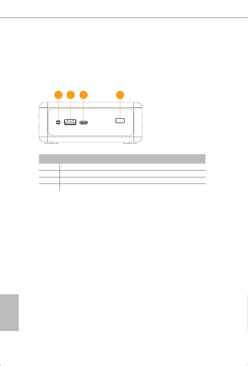
2.1 Front View
1 2 3 4
No. Description
1 Headphone & Microphone
2 USB 3.0 (Type A)
3 USB 3.0 (Type C)
4 IR Sensor Window
English
4 5
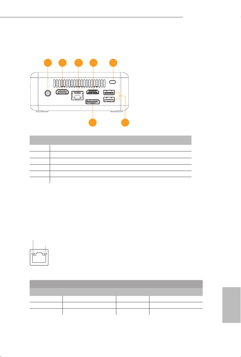
2.2 Rear View
1 2 33 2 4
No. Description
1 DC-In
2 HDMI
3 RJ-45
4 Kensington Lock Slot
5 USB 3.0 (Type A)
6 *DisplayPort
Beebox series
56
*To use DisplayPort as a display output, please connect your monitor/display to
HDMI Port when installing OS system.
is DisplayPort only supports DP to D-Sub dongle and does not support DP to
HDMI dongle and DP to DVI dongle.
* ere are two LEDs on the LAN port. Please refer to the table below for the LAN port LED indications.
ACT/LINK LED
SPEED LED
LAN Por t
Activity / Link LED Speed LED
Status Description Status Description
O No Link O 10Mbps connection
Blinking Data Activity Orange 100Mbps connection
On Link Green 1Gbps connection
English
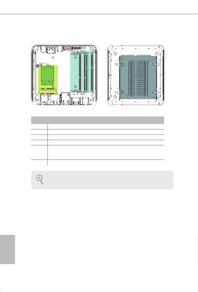
2.3 Inside View
6
4
5
3
1
2
No. Description
1 M.2 WiFi Module
2 mSATA Slot
3 SATA 3.0 Connector
4 SO-DIMM Slots
5 Clear CMOS Pad
*Clear CMOS Pad allows you to clear th e data in CMOS. To clear CMOS, disconnect the
power supply and short the Clear CMOS Pad.
6 Hard disk drive tray (compatible with 2.5" SATA HDD)
SO-DIM M memory, hard drive and mSATA SSD are not inclu ded with this system.
English
6 PB

Chapter 3 Hardware Installation
is chapter helps you install or remove important components.
3.1 How to Remove the Bottom Case
1. Remove the four screws on the bottom case.
2. en li up and remove the bottom panel..
1
2
Beebox series
English
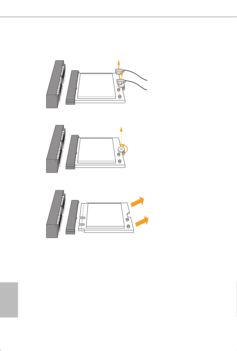
3.2 How to Remove the M.2 WiFi Module
1. Disconnect the two antenna cables from the M.2 WiFi Module by liing the clips.
2. Remove the screw that holds the M.2 WiFi Module in place.
3. Carefully pull the M.2 WiFi Module from the slot and remove it.
English
8 9

3.3 How to Install the mSATA SSD
1. Locate the mSATA slot on the motherboard
2. Carefully insert the mSATA SSD into the slot.
3. Tighten the screw to secure the mSATA SSD to the motherboard.
.
Beebox series
English

3.4 How to Install the 2.5-inch Hard Drive
1. Remove the four screws on the bottom case. en li up and remove the bottom panel.
2. Unscrew the four screws that hold the HDD cage in place.
3. Install the HDD in the cage using the four screws. en connect the SATA cable to the
HDD.
English
10 11

Beebox series
4. Attach the HDD cage to the bottom panel and secure it using the four screws.
5. Connect the SATA Data and Power Cable to the motherboard and reinstall the bottom
panel.
6. Align the three latches on the bottom panel with the three latch holes on the chassis.
en reinstall the bottom panel until it
7. clicks into place.
English
 Loading...