

Page 1
Version 1.1
Published June 2014
Copyright©2014 ASRock INC. All rights reserved.
Copyright Notice:
No part of this documentation may be reproduced, transcribed, transmitted, or
translated in any language, in any form or by any means, except duplication of
documentation by the purchaser for backup purpose, without written consent of
ASRock Inc.
Products and corporate names appearing in this documentation may or may not
be registered trademarks or copyrights of their respective companies, and are used
only for identication or explanation and to the owners’ benet, without intent to
infringe.
Disclaimer:
Specications and information contained in this documentation are furnished for
informational use only and subject to change without notice, and should not be
constructed as a commitment by ASRock. ASRock assumes no responsibility for
any errors or omissions that may appear in this documentation.
With respect to the contents of this documentation, ASRock does not provide
warranty of any kind, either expressed or implied, including but not limited to
the implied warranties or conditions of merchantability or tness for a particular
purpose.
In no event shall ASRock, its directors, ocers, employees, or agents be liable for
any indirect, special, incidental, or consequential damages (including damages for
loss of prots, loss of business, loss of data, interruption of business and the like),
even if ASRock has been advised of the possibility of such damages arising from any
defect or error in the documentation or product.
is device complies with Part 15 of the FCC Rules. Operation is subject to the following
two conditions:
(1) this device may not cause harmful interference, and
(2) this device must accept any interference received, including interference that
may cause undesired operation.
CALIFORNIA, USA ONLY
e Lithium battery adopted on this motherboard contains Perchlorate, a toxic substance
controlled in Perchlorate Best Management Practices (BMP) regulations passed by the
California Legislature. When you discard the Lithium battery in California, USA, please
follow the related regulations in advance.
“Perchlorate Material-special handling may apply, see ww w.dtsc.ca.gov/hazardouswaste/
perchlorate”
ASRock Website: http://www.asrock.com
Page 2

Page 3

B95M-DGS
1
English
Motherboard Layout
Intel
B85
DDR 3_B1 (6 4 bit, 24 0-pin m odule )
DDR 3_A1 (6 4 bit, 24 0-pin m odule )
CMO S
Bat tery
Sup er
I/O
ATXP WR 1
LAN
Top:
RJ- 45
USB 2 .0
T: USB2
B: US B3
CLRCMO S1
1
1
SPEAKER1
HDLED RESET
PLED P WRBTN
PANEL1
1
USB4_5
1
COM1
1
1
HD_AU DIO1
B95M-DGS
CHA_FA N1
RoHS
CPU_FAN1
32Mb
BIOS
VGA1
Audio
CODEC
PCIE1
Fro nt USB 3. 0
PWR_FA N1
1
TPMS1
1
1
LPT1
CI1
1
USB3 _2_3
SATA3_3
PCIE2
USB 3. 0
T: USB0
B: US B1
Top:
LINE IN
Cente r:
FRONT
Botto m:
MIC IN
USB6_7
1
ATX12V 1
SATA3_1
SATA3_2
SATA3_0
PCI Express 3 .0
USB 2. 0
T: USB0
B: USB 1
PS2
Keyb oard/
Mous e
DVI1
Page 4

2
English
No. Description
1 CPU Fan Connector (CPU_FAN1)
2 ATX 12V Power Connector (ATX12V1)
3 Power Fan Connector (PWR _FAN1)
4 2 x 240-pin DDR3 DIMM Slots (DDR3_A1, DDR3_B1)
5 ATX Power Connector (ATXPWR1)
6 SATA3 Connector (SATA3_3)
7 SATA3 Connector (SATA3_2)
8 SATA3 Connector (SATA3_0)
9 SATA3 Connector (SATA3_1)
10 USB 3.0 Header (USB3_ 2_ 3)
11 Clear CMOS Jumper (CLRCMOS1)
12 System Panel Header (PANEL1)
13 TPM Header (TPMS1)
14 USB 2.0 Header (USB6_7)
15 Chassis Speaker Header (SPEAKER1)
16 USB 2.0 Header (USB4_5)
17 Chassis Fan Connector (CHA_FAN1)
18 Print Port Header (LPT1)
19 COM Port Header (COM1)
20 Chassis Intrusion Header (CI1)
21 Front Panel Audio Header (HD_AUDIO1)
Page 5
B95M-DGS
3
English
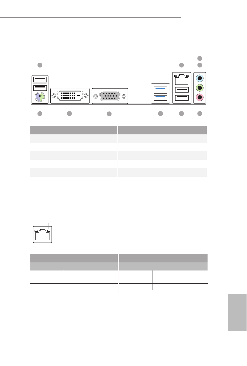
I/O Panel
No. Description No. Description
1 USB 2.0 Ports (USB01) 6 USB 2.0 Ports (USB23)
2 LAN RJ-45 Port* 7 USB 3.0 Ports (USB3_01)
3 Line In (Light Blue) 8 D-Sub Port
4 Front Speaker (Lime) 9 DVI-D Port
5 Microphone (Pink) 10 PS/2 Mouse/Keyboard Port
* ere are two LEDs on each LAN port. Please refer to the table below for the LAN port LED indications .
Activity / Link LED Speed LED
Status Description Status Description
O No Link O 10Mbps connection
Blinking Data Activity Orange 100Mbps connection
On Link Green 1Gbps connection
ACT/LINK L ED
SPEED LE D
LAN Por t
2 4
5679
8
3
10
1
Page 6
4
English
1 Introduction
ank you for purchasing ASRock B95M-DGS motherboard, a reliable motherboard
produced under ASRock’s consistently stringent quality control. It delivers excellent
performance with robust design conforming to ASRock ’s commitment to quality
and endurance.
1.1 Package Contents
•
ASRock B95M-DGS Motherboard (Micro ATX Form Factor)
•
ASRock B95M-DGS Quick Installation Guide
•
ASRock B95M-DGS Support CD
•
2 x Serial ATA (SATA) Data Cables (Optional)
•
1 x I/O Panel Shield
Becau se the motherboard specications and the BIOS soware might be updated, the
content of this documentation will be subject to change without notice. In case any
modications of this documentation occur, the updated version will be available on
ASRock’s website w ithout f urther notice. If you require technical support relate d to
this motherboard, please vi sit our website for s pecic information about the model
you are using. You may nd the l atest VGA cards and CPU suppor t list on ASRock’s
website a s well. ASRock website ht tp://www.a srock.com.
Page 7

B95M-DGS
5
English
1.2 Specications
Platform
•
Micro ATX Form Factor
•
Solid Capacitor design
•
High Density Glass Fabric PCB
CPU
•
Supports New 4th and 4th Generation Intel® CoreTM i7/i5/i3/
Xeon®/Pentium®/Celeron® Processors (Socket 1150)
•
Supports Intel® Turbo Boost 2.0 Technology
Chipset
•
Intel® B85
Memory
•
Dual Channel DDR3 Memory Technology
•
2 x DDR3 DIMM Slots
•
Supports DDR3 1600/1333/1066 non-ECC, un-buered
memory
•
Max. capacity of system memory: 16GB (see CAUTION)
•
Supports Intel® Extreme Memory Prole (XMP) 1.3 / 1.2
Expansion
Slot
•
1 x PCI Express 3.0 x16 Slot (PCIE1: x16 mode)
•
1 x PCI Express 2.0 x1 Slot
Graphics
•
Intel® HD Graphics Built-in Visuals and the VGA outputs can
be supported only with processors which are GPU integrated.
•
Supports Intel® HD Graphics Built-in Visuals : Intel® Quick
Sync Video with AVC, MVC (S3D) and MPEG-2 Full
HW Encode1, Intel® InTruTM 3D, Intel® Clear Video HD
Technology, Intel® InsiderTM, Intel® HD Graphics 4400/4600
•
Pixel Shader 5.0, DirectX 11.1
•
Max. shared memory 1792MB
•
Dual graphics output: support DVI-D and D-Sub by
independent display controllers
•
Supports DVI-D with ma x. resolution up to 1920x1200 @
60Hz
•
Supports D-Sub with max. resolution up to 1920x1200 @
60Hz
•
Supports HDCP with DVI-D Port
•
Supports Full HD 1080p Blu-ray (BD) playback with DVI-D
Port
Page 8

6
English
Audio
•
5.1 CH HD Audio (Realtek ALC662 Audio Codec)
•
Supports Surge Protection (ASRock Full Spike Protection)
•
ELNA Audio Caps
LAN
•
PCIE x1 Gigabit LAN 10/100/1000 Mb/s
•
Realtek RTL8111GR
•
Supports Wake-On-WAN
•
Supports Wake-On-LAN
•
Supports Lightning/ESD Protection (ASRock Full Spike
Protection)
•
Supports LAN Cable Detection
•
Supports Energy Ecient Ethernet 802.3az
•
Supports PXE
Rear Panel
I/O
•
1 x PS/2 Mouse/Keyboard Port
•
1 x D-Sub Port
•
1 x DVI-D Port
•
4 x USB 2.0 Ports (Supports ESD Protection (ASRock Full
Spike Protection))
•
2 x USB 3.0 Ports (Supports ESD Protection (ASRock Full
Spike Protection))
•
1 x RJ-45 LAN Port with LED (ACT/LINK LED and SPEED
LED)
•
HD Audio Jacks: Line in / Front Speaker / Microphone
Storage
•
4 x SATA3 6.0 Gb/s Connectors, support NCQ, AHCI and
Hot Plug
Connector
•
1 x Print Port Header
•
1 x COM Port Header
•
1 x Chassis Intrusion Header
•
1 x TPM Header
•
1 x CPU Fan Connector (4-pin)
•
1 x Chassis Fan Connector (4-pin)
•
1 x Power Fan Connector (3-pin)
•
1 x 24 pin ATX Power Connector
•
1 x 4 pin 12V Power Connector
•
1 x Front Panel Audio Connector
Page 9

B95M-DGS
7
English
•
2 x USB 2.0 Headers (Support 4 USB 2.0 ports) (Supports ESD
Protection (ASRock Full Spike Protection))
•
1 x USB 3.0 Header (Supports 2 USB 3.0 ports) (Supports ESD
Protection (ASRock Full Spike Protection))
BIOS
Feature
•
32Mb AMI UEFI Legal BIOS with multilingual GUI support
•
ACPI 1.1 Compliant wake up events
•
SMBIOS 2.3.1 support
•
CPU, DRAM, PCH 1.05V, PCH 1.5V Voltage multi-adjust-
ment
Hardware
Monitor
•
CPU/Chassis temperature sensing
•
CPU/Chassis/Power Fan Tachometer
•
CPU/Chassis Quiet Fan (Auto adjust chassis fan speed by
CPU temperature)
•
CPU/Chassis Fan multi-speed control
•
CASE OPEN detection
•
Voltage monitoring: +12V, +5V, +3.3V, CPU Vcore
OS
•
Microso® Windows® 8.1 32-bit / 8.1 64-bit / 8 32-bit / 8 64-
bit / 7 32-bit / 7 64-bit
Certications
•
FCC, CE, WHQL
•
ErP/EuP ready (ErP/EuP ready power supply is required)
Please realize that the re is a certain r isk involved with overclo cking, including adju sting the setting in the BIOS, applying Untied Ove rclocking Technology, or using thirdparty o verclocking tools. Overclocking may aect your system’s stability, or even c ause
damage to the components and dev ices of your system. It should be done at your own
risk and expense. We are not responsible for possible damage cau sed by overclocking.
* For detailed product information, please visit our website: http://ww w.asrock.com
Due to limitation, the actual memory size may be less than 4GB for the reservation
for system usage under Windows® 32- bit operating systems . Windows® 64-bit operating systems do not have such limitations. You can use ASRock XFast RAM to utilize
the memory that Windows® cannot use.
Page 10

8
English
1.3 Jumpers Setup
e illustration shows how jumpers are setup. When the jumper cap is placed on
the pins, the jumper is “Short”. If no jumper cap is placed on the pins, the jumper
is “Open”. e illustration shows a 3-pin jumper whose pin1 and pin2 are “Short”
when a jumper cap is placed on these 2 pins.
Clear CMOS Jumper
(CLRCMOS1)
(see p.1, No. 11)
CLRCMOS1 allows you to clear the data in CMOS. To clear and reset the system
parameters to default setup, please turn o the computer and unplug the power
cord from the power supply. Aer waiting for 15 seconds, use a jumper cap to
short pin2 and pin3 on CLRCMOS1 for 5 seconds. However, please do not clear
the CMOS right aer you update the BIOS. If you need to clear the CMOS when
you just nish updating the BIOS, you must boot up the system rst, and then shut
it down before you do the clear-CMOS action. Please be noted that the password,
date, time, and user default prole will be cleared only if the CMOS battery is
removed.
Clear CMOSDefault
If you clear the CMOS, the case open may be detec ted. Please adjust the BIOS option
“Clear Status” to clear the record of previou s chassis intrusion status.
Page 11

B95M-DGS
9
English
1.4 Onboard Headers and Connectors
System Panel Header
(9-pin PANEL1)
(see p.1, No. 12)
Connect the power
switch, reset switch and
system status indicator on
the chassis to this header
according to the pin
assignments below. Note
the positive and negative
pins before connecting
the cables.
GND
RES ET#
PWR BTN#
PLE D-
PLE D+
GND
HDL ED-
HDL ED+
1
GND
PWRBTN (Power Switch):
Connec t to the power switch on the chassi s front panel. You may congure the way to
turn o your system using the power switch.
RESET (Reset Switch):
Connec t to the reset switch on the chassi s front panel. P ress the reset sw itch to restart
the computer if the compute r freezes and fails to perform a normal restart.
PLED (Syste m Power LED):
Connec t to the power status indicator on the chassis front panel. e LED i s on when
the system is ope rating. e LED keeps blinking when the system i s in S1/S3 sleep state.
e LED is o when the system i s in S4 sle ep state or powered o (S5).
HDLED (Ha rd Drive Activity LED):
Connec t to the hard drive ac tivity LED on the chassis front panel. e LED is on when
the hard dr ive is reading or w riting data.
e front panel de sign may dier by chassis. A front pane l module mainly consists
of power switch , reset switch, power LED, hard dr ive activity LED, speak er and etc.
When connecting your chassis front panel module to this head er, make sure the wire
assig nments and the pin assig nments are matched correctly.
Onboard headers and connectors are NOT jumpers. Do NOT place jumper caps over
these header s and connectors. Placing jumper caps over the headers and connectors
will cause permanent damage to the motherboard.
Page 12

10
English
Serial ATA3 Connectors
(SATA3_0:
see p.1, No. 8)
(SATA3_1:
see p.1, No. 9)
(SATA3_2:
see p.1, No. 7)
(SATA3_3:
see p.1, No. 6)
ese four SATA3
connectors support SATA
data cables for internal
storage devices with up to
6.0 Gb/s data transfer rate.
USB 2.0 Headers
(9-pin USB4_ 5)
(see p.1, No. 16)
(9-pin USB6_7)
(see p.1, No. 14)
Besides four USB 2.0 ports
on the I/O panel, there
are two headers on this
motherboard. Each USB
2.0 header can support
two ports.
USB 3.0 Header
(19-pin USB3_2_3)
(see p.1, No. 10)
Besides two USB 3.0 ports
on the I/O panel, there
is one header on this
motherboard. Each USB
3.0 header can support
two ports.
Front Panel Audio Header
(9-pin HD_AUDIO1)
(see p.1, No. 21)
is header is for
connecting audio devices
to the front audio panel.
DUM MY
GND
GND
P+
P-
USB _PW R
P+
P-
USB _PW R
1
1
IntA _PB_D +
Dumm y
IntA _PB_D -
GND
IntA _PB_S STX+
GND
IntA _PB_S STX-
IntA _PB_S SRX+
IntA _PB_S SRX-
VbusVbus
Vbus
IntA _PA_SS RX-
IntA _PA_SS RX+
GND
IntA _PA_SS TX-
IntA _PA_SS TX+
GND
IntA _PA_D-
IntA _PA_D+
J_S ENSE
OUT 2_L
1
MIC _RET
PRE SENCE #
GND
OUT 2_R
MIC 2_R
MIC 2_L
OUT _RET
SATA3_1
SATA3_0
SATA3_3
SATA3_2
Page 13

B95M-DGS
11
English
Chassis Speaker Header
(4-pin SPEAKER1)
(see p.1, No. 15)
Please connect the chassis
speaker to this header.
Chassis and Power Fan
Connectors
(4-pin CHA_FAN1)
(see p.1, No. 17)
(3-pin PWR_FAN1)
(see p.1, No. 3)
Please connect fan cables
to the fan connectors and
match the black wire to
the ground pin.
CPU Fan Connector
(4-pin CPU_FAN1)
(see p.1, No. 1)
is motherboard pro-
vides a 4-Pin CPU fan
(Quiet Fan) connector.
If you plan to connect a
3-Pin CPU fan, please
connect it to Pin 1-3.
ATX Power Connector
(24-pin ATXPWR1)
(see p.1, No. 5)
is motherboard pro-
vides a 24-pin ATX power
connector. To use a 20-pin
ATX power supply, please
plug it along Pin 1 and Pin
13.
1. High Denition Au dio supports Jack Sen sing, b ut the panel wire on the chassis mu st
suppor t HDA to function correctly. Please follow the instructions in our manual and
chassis manual to install your syste m.
2. If you use an AC’97 audio panel , please install it to th e front panel audio header by
the steps below:
A. Connect Mic_IN (MIC) to MIC2_ L.
B. Conne ct Audio_R (RIN) to OUT2_R and Audio_ L (LIN) to OUT2_ L.
C. Connect Ground (GND) to Ground (GND).
D. MIC_ RET and OUT_RET are for the HD audio panel only. You don’t need to
connec t them for the AC’97 audio panel.
E. To activate the front mic, go to the “FrontMic” Tab in the Realtek Control panel
and adju st “Recording Volume”.
1
+5V
DUM MY
DUM MY
SPE AKER
12
1
24
13
GND
+12 V
FAN_ SPEED
FAN_S PEED
FAN_S PEED_ CONTR OL
GND
+12V
1 2 3 4
FAN_S PEED
FAN_S PEED_ CONTR OL
+12V
GND
4
3
2
1
Page 14

12
English
ATX 12V Power
Connector
(4-pin ATX12V1)
(see p.1, No. 2)
Please connect an ATX
12V power supply to this
connector.
Serial Port Header
(9-pin COM1)
(see p.1, No. 19)
is COM1 header
supports a serial port
module.
Chassis Intrusion Header
(2-pin CI1)
(see p.1, No. 20)
is motherboard
supports CASE OPEN
detection feature that
detects if the chassis cove
has been removed. is
feature requires a chassis
with chassis intrusion
detection design.
TPM Header
(17-pin TPMS1)
(see p.1, No. 13)
is connector supports
Trusted Platform Module
(TPM) system, which can
securely store keys, digital
certicates, passwords,
and data. A TPM system
also helps enhance
network securit y, protects
digital identities, and
ensures platform integrity.
CCTS #1
RRTS #1
DDSR #1
DDTR #1
RRXD 1
GND
TTXD 1
DDCD #1
1
RRI# 1
1
Sig nal
GND
1
GND
SMB _DATA _MAIN
LAD 2
LAD 1
GND
S_P WRDWN #
SER IRQ#
GND
PCI CLK
PCI RST#
LAD 3
+3V
LAD 0
+3V SB
GND
FRA ME
SMB _CLK_ MAIN
Page 15

B95M-DGS
13
English
Print Port Header
(25-pin LPT1)
(see p.1, No. 18)
is is an interface
for print port cable
that allows convenient
connection of printer
devices.
1
AFD #
ERR OR#
PIN IT#
GND
SLI N#
STB #
SPD 0
SPD 1
SPD 2
SPD 3
SPD 4
SPD 5
SPD 6
SPD 7
ACK #
BUS Y
PE
SLC T
Page 16

14
简体中文
规格
平台
•Micro ATX 规格尺寸
•固态电容器设计
•高密度防潮纤维电路板
CPU
•支持新款第 4 代和第 4 代 Intel® Core
TM
i7/i5/i3/Xeon®/
Pentium®/Celeron® 处理器 (Socket 1150)
•支持 Intel® Turbo Boost 2.0 技术
芯片集
•Intel® B85
内存
•双通道 DDR3 内存技术
•2 x DDR3 DIMM 槽
•支持 DDR3 1600/1333/1066 非 ECC,非缓冲内存
•支持系统内存容量: 16GB
•支持 Intel® Extreme Memory Prole (XMP)1.3/1.2
扩充槽
•1 x PCI Express 3.0 x16 槽 (PCIE1: x16 模式 )
•1 x PCI Express 2.0 x1 槽
图形
•只有 GPU 集成的处理器才支持 Intel® HD Graphics 内置视
效和 VGA 输出。
•支持 Intel® HD Graphics 内置视效 : Intel® 快速同步视频,采
用 AVC、MVC (S3D) 和 MPEG-2 Full HW Encode1、Intel®
InTruTM 3D、Intel® Clear Video HD 技术、Intel® InsiderTM、
Intel® HD Graphics 4400/4600
•Pixel Shader 5.0、DirectX 11.1
•最大共享内存 1792MB
•双重显示输出选项 : 通过独立显示控制器提供 DVI-D 和
D-Sub 接口
•支持 DVI-D,60Hz 时最大分辨率达 1920x1200
•支持 D-Sub,60Hz 时最大分辨率达 1920x1200
•通过 DVI-D 端口支持 HDCP 功能
•通过 DVI-D 端口支持全高清 1080p Blu-ray (BD) 播放
Page 17

15
简体中文
B95M-DGS
音频
•5.1 CH 高清音频(Realtek ALC662 音频编解码器)
•支持防突波 ( 华擎全防护 )
•ELNA 专业音效电容
LAN
•PCIE x1 Gigabit LAN 10/100/1000 Mb/s
•Realtek RTL8111GR
•支持远端開机功能 (Wake-On-WAN)
•支持 Wake-On-LAN(网上唤醒)
•支持防雷击 / 防 ESD 静电 ( 华擎全防护 )
•支持网路綫侦测功能
•支持高能效以太网 802.3az
•支持 PXE
后面板 I/O
•1 x PS/2 鼠标 / 键盘端口
•1 x D-Sub 端口
•1 x DVI-D 端口
•4 x USB 2.0 端口 ( 支持防 ESD 静电 ( 华擎全防护 ))
•2 x USB 3.0 端口 ( 支持防 ESD 静电 ( 华擎全防护 ))
•1 x RJ-45 LAN 端口,带 LED(ACT/LINK LED 和 SPEED
LED)
•高清音频插孔 : 线路输入 / 前扬声器 / 麦克风
存储
•4 x SATA3 6.0 Gb/s 接口,支持 NCQ、AHCI 和“热插拔”
功能
接口
•1 x 打印端口接脚
•1 x COM 端口接脚
•1 x 机箱侵入接脚
•1 x TPM 接脚
•1 x CPU 风扇接口 (4 针 )
•1 x 机箱风扇接口 (4 针 )
•1 x 电源风扇接口 (3 针 )
•1 x 24 针 ATX 电源接口
•1 x 4 针 12V 电源接口
•1 x 前面板音频接口
•2 x USB 2.0 接脚(支持 4 个 USB 2.0 端口)( 支持防 ESD 静
电 ( 华擎全防护 ))
Page 18

16
简体中文
•1 x USB 3.0 接脚(支持 2 个 USB 3.0 端口)( 支持防 ESD 静
电 ( 华擎全防护 ))
BIOS 功能特点
•32Mb AMI UEFI Legal BIOS,具有多语言 GUI 支持
•ACPI 1.1 兼容唤醒事件
•SMBIOS 2.3.1 支持
•CPU、DRAM、PCH 1.05V、PCH 1.5V 电压多次调整(Voltage
Multi-adjustment)
硬件监控
•CPU/ 机箱温度感测
•CPU/ 机箱 / 电源风扇转速计
•CPU/ 机箱静音风扇(可以按照 CPU 温度自动调整机箱风
扇速度)
•CPU/ 机箱风扇多种速度控制
•CASE OPEN(机箱打开)检测
•电压监控: +12V、+5V、+3.3V、CPU Vcore
操作系统
•Microso® Windows® 8.1 32-bit / 8.1 64-bit / 8 32-bit / 8 64-
bit / 7 32-bit / 7 64-bit
认证
•FCC、CE、WHQL
•ErP/EuP 支持(需要支持 ErP/EuP 的电源)
Page 19

17
简体中文
B95M-DGS
電子信息產品污染控制標示
依據中國發布的「電子信息產品污染控制管理辦法」及 SJ/T 11364-2006「電
子信息產品污染控制標示要求」,電子信息產品應進行標示,藉以向消費者揭
露產品中含有的有毒有害物質或元素不致發生外洩或突變從而對環境造成污染
或對人身、財產造成嚴重損害的期限。依上述規定,您可于本產品之印刷電路
板上看見圖一之標示。圖一中之數字為產品之環保使用期限。由此可知此主板
之環保使用期限為 10 年。
圖一
有毒有害物質或元素的名稱及含量說明
若您慾了解此產品的有毒有害物質或元素的名稱及含量說明,請參照以下表格
及說明。
有害物質或元素
鉛(Pb) 鎘 (Cd) 汞 (Hg) 六价鉻 (Cr(VI)) 多溴聯苯 (PBB) 多溴二苯醚 (PBDE)
印刷電路板
及電子組件
外部信號連
接頭及線材
部件名稱
X O O O O O
X O O O O O
O:
表示該有毒有害物質在該部件所有均質材料中的含量均在 SJ/T 11363-2006 標準規定
的限量要求以下。
X:
表示該有毒有害物質至少在該部件的某一均質材料中的含量超出 SJ/T 11363-2006 標準
規定的限量要求,然該部件仍符合歐盟指令 2002/95/EC 的規範。
備註 : 此產品所標示之環保使用年限,系指在一般正常使用狀況下。
Page 20

18
繁體中文
規格
平台
• Micro ATX 尺寸
• 固態電容設計
• 高密度防潮纖維電路板
CPU
• 支援全新第 4 代及第 4 代 Intel® Core
TM
i7/i5/i3/Xeon®/
Pentium®/Celeron® 處理器 (Socket 1150)
• 支援 Intel® Turbo Boost 2.0 技術
晶片組
• Intel® B85
記憶體
• 雙通道 DDR3 記憶體技術
• 2 x DDR3 DIMM 插槽
• 支援 DDR3 1600/1333/1066 非 ECC、無緩衝記憶體
• 最大系統記憶體容量: 16GB
• 支援 Intel® Extreme Memory Prole (XMP)1.3/1.2
擴充插槽
• 1 x PCI Express 3.0 x16 插槽(PCIE1: x16 模式)
• 1 x PCI Express 2.0 x1 插槽
顯示卡
• 僅限整合 GPU 的處理器才可支援 Intel® HD Graphics Built-
in Visuals 及 VGA 輸出。
• 支援 Intel® HD Graphics Built-in Visuals: 轉換 AVC、
MVC (S3D) 及 MPEG-2 Full HW Encode1 的 Intel® 高速影
像同步轉檔技術、Intel® InTruTM 3D、Intel® Clear Video HD
Technology、Intel® InsiderTM、Intel® HD Graphics 4400/4600
• Pixel Shader 5.0,DirectX 11.1
• 最大共用記憶體 1792MB
• 雙顯示輸出 : 透過獨立顯示控制器提供 DVI-D 和 D-Sub 接
口
• 支援最高達 1920x1200 @ 60Hz 解析度的 DVI-D
• 支援最高達 1920x1200 @ 60Hz 解析度的 D-Sub
• 支援含 DVI-D 連接埠的 HDCP 功能
• 支援透過 DVI-D 連接埠的 Full HD 1080p Blu-ray (BD) 播
放
Page 21

19
繁體中文
B95M-DGS
音訊
• 5.1 CH HD 音訊(Realtek ALC662 音訊轉碼器)功能
• 支援防突波 (ASRock 全防護 )
• ELNA 音效專用電容
LAN
• PCIE x1 Gigabit LAN 10/100/1000 Mb/s
• Realtek RTL8111GR
• 支援 Wake-On-WAN
• 支援網路喚醒
• 支援防雷擊 / 防 ESD 靜電 (ASRock 全防護 )
• 支援網路線偵測功能
• 支援 Energy Ecient Ethernet 802.3az
• 支援 PXE
後面板 I/O
• 1 x PS/2 滑鼠/鍵盤連接埠
• 1 x D-Sub 連接埠
• 1 x DVI-D 連接埠
• 4 x USB 2.0 連接埠 ( 支援防 ESD 靜電 (ASRock 全防護 )
• 2 x USB 3.0 連接埠 ( 支援防 ESD 靜電 (ASRock 全防護 )
• 1 x RJ-45 LAN 連接埠,含 LED(ACT/LINK LED 及 SPEED
LED)
• HD 音訊插孔: 線路輸入/前置喇叭/麥克風
儲存裝置
• 4 x SATA3 6.0 Gb/s 接頭,支援 NCQ、AHCI 及「熱插拔」功能
接頭
• 1 x 列印連接埠標頭
• 1 x COM 連接埠標頭
• 1 x 機殼防護標頭
• 1 x TPM 標頭
• 1 x CPU 風扇接頭 (4-pin)
• 1 x 機殼風扇接頭 (4-pin)
• 1 x 電源風扇接頭 (3-pin)
• 1 x 24 pin ATX 電源接頭
• 1 x 4 pin 12V 電源接頭
• 1 x 前面板音訊接頭
• 2 x USB 2.0 標頭(支援 4 USB 2.0 連接埠)( 支援防 ESD 靜
電 (ASRock 全防護 )
• 1 x USB 3.0 標頭(支援 2 USB 3.0 連接埠)( 支援防 ESD 靜
電 (ASRock 全防護 )
Page 22

20
繁體中文
BIOS 功能
• 32Mb AMI UEFI Legal BIOS 含 多語 GUI 支援
• ACPI 1.1 符合喚醒自動開機
• 支援 SMBIOS 2.3.1
• CPU、DR AM、PCH 1.05V、PCH 1.5V 電壓多重調整
硬體監視器
• CPU /機殼溫度感應
• CPU /機殼/電源風扇轉速計
• CPU /機殼靜音風扇(允許按照 CPU 溫度自動調整機殼風
扇速度)
• CPU /機殼風扇多重速度控制
• 機殼開啟偵測
• 電壓監控: +12V、+5V、+3.3V、CPU Vcore
作業系統
• Microso® Windows® 8.1 32 位元 /8.1 64 位元 /8 32 位元 /8
64 位元 /7 32 位元 /7 64 位元
認證
• FCC、CE、WHQL
• ErP/EuP Ready(需具備 ErP/EuP ready 電源供應器)
Page 23

21
Bahasa Indonesia
B95M-DGS
Spesikasi
Platform
•Bentuk dan Ukuran Micro ATX
•Desain Kapasitor Solid
•PCB Serat Kaca dengan Kerapatan Tinggi
CPU
•Mendukung Prosesor Intel® Core
TM
i7/i5/i3/Xeon®/Pentium®/
Celeron® Generasi ke-4 Baru, dan ke-4 (Soket 1150)
•Mendukung Teknologi Intel® Turbo Boost 2.0
Chipset
•Intel® B85
Memori
•Teknologi Memori DDR3 Kanal Ganda
•2 x Slot DDR3 DIMM
•Mendukung DDR3 1600/1333/1066 non-ECC, memori tanpa
buer
•Kapasitas maksimum memori sistem: 16GB
•Mendukung Intel® Extreme Memory Prole (XMP)1.3/1.2
Slot Ekspansi
•1 x Slot PCI Express 3.0 x16 (PCIE1: x16 mode)
•1 x Slot PCI Express 2.0 x1
Gras
•Intel® HD Graphics Built-in Visuals dan output VGA hanya
didukung dengan prosesor yang terintegrasi GPU.
•Mendukung Intel® HD Graphics Built-in Visuals: Intel® Quick
Sync Video dengan AVC, MVC (S3D), dan MPEG-2 Full HW
Encode1, Intel® InTruTM 3D, Teknologi Intel® Clear Video HD,
Intel® InsiderTM, Intel® HD Graphics 4400/4600
•Pixel Shader 5.0, DirectX 11.1
•Memori bersama maksimum 1792MB
•Output VGA Ganda: mendukung port DVI-D dan D-Sub
•Mendukung DVI-D dengan resolusi maksimum hingga
1920x1200 @ 60Hz
•Mendukung D-Sub dengan resolusi maksimum hingga
1920x1200 @ 60Hz
•Mendukung fungsi HDCP dengan port DVI-D
•Mendukung pemutaran Full HD 1080p Blu-ray (BD) dengan
port DVI-D
Page 24

22
Bahasa Indonesia
Audio
•Audio HD 5.1 CH (Realtek ALC662 Audio Codec)
•Mendukung Perlindungan Lonjakan Arus (ASRock Full
Spike Protection)
•ELNA Audio Caps
LAN
•PCIE x1 Gigabit LAN 10/100/1000 Mb/s
•Realtek RTL8111GR
•Menggunakan Wake-On-WAN
•Mendukung Wake-On-LAN
•Mendukung Perlindungan Petir/ESD (Perlindungan Penuh
Lonjakan Tegangan ASRock)
•Mendukung Deteksi Kabel LAN
•Mendukung Energy Ecient Ethernet 802.3az
•Mendukung PXE
Panel I/O
Belakang
•1 x Port Mouse/Keyboard PS/2
•1 x Port D-Sub
•1 x Port DVI-D
•4 x Port USB 2.0 (Mendukung Perlindungan ESD (ASRock
Full Spike Protection))
•2 x Port USB 3.0 (Mendukung Perlindungan ESD (ASRock
Full Spike Protection))
•1 x Port LAN RJ-45 dengan LED (ACT/LINK LED dan
SPEED LED)
•Soket Audio HD: Saluran masuk/Speaker Depan/Mik rofon
Penyimpanan
•4 x Konektor SATA3 6,0 Gb/s, mendukung fungsi NCQ,
AHCI, dan “Hot Plug”
Konektor
•1 x Header port Cetak
•1 x Header port COM
•1 x Header Intrusi Chassis
•1 x Header TPM
•1 x Konektor kipas CPU (4-pin)
•1 x Konektor kipas chassis (4-pin)
•1 x Konektor kipas daya (3-pin)
•1 x Konektor daya ATX 24 pin
•1 x Konektor daya 12V 4 pin
•1 x Konektor audio panel depan
Page 25

23
Bahasa Indonesia
B95M-DGS
•2 x Header USB 2.0 (mendukung 4 port USB 2.0) (Mendukung
Perlindungan ESD (ASRock Full Spike Protection))
•1 x Header USB 3.0 (mendukung 2 port USB 3.0) (Mendukung
Perlindungan ESD (ASRock Full Spike Protection))
Fitur BIOS
•32Mb AMI UEFI Legal BIOS dengan dukungan GUI
Multibahasa
•ACPI 1.1 Kompatibel dengan Aktivitas Pengaktifan
•Dukugan SMBIOS 2.3.1
•Multipengatur Tegangan CPU, DRAM, PCH 1,05V, PCH 1,5V
Perangkat
Keras Monitor
•Sensor Suhu CPU/Chassis
•Takometer CPU/Chassis/Kipas Daya
•Kipas Hening CPU/Chassis (Memungkinkan Penyesuaian
Otomatis Kecepatan Kipas Chassis Berdasarkan Suhu CPU)
•Kontrol Multikecepatan Kipas CPU/Chassis
•Deteksi CASE OPEN
•Pemantauan Tegangan: +12V, +5V, +3,3V, CPU Vcore
OS
•Microso® Windows® 8.1 32-bit / 8.1 64-bit / 8 32-bit / 8 64-
bit / 7 32-bit / 7 64-bit
Sertikasi
•FCC, CE, WHQL
•Siap untuk ErP/EuP (memerlukan catu daya untuk ErP/EuP)
Page 26

Contact Information
If you need to contact ASRock or want to know more about ASRock, you’re welcome
to visit ASRock’s website at http://ww w.asrock.com; or you may contact your dealer
for further information. For technical questions, please submit a support request
form at http://www.asrock.com/support/tsd.asp
ASRock Incorporation
2F., No.37, Sec. 2, Jhongyang S. Rd., Beitou District,
Taipei City 112, Taiwan (R.O.C.)
ASRock EUROPE B.V.
Bijsterhuizen 3151
6604 LV Wijchen
e Netherlands
Phone: +31-24-345-44-33
Fax: +31-24-345-44-38
ASRock America, Inc.
13848 Magnolia Ave, Chino, CA91710
U.S.A.
Phone: +1-909-590-8308
Fax: +1-909-590-1026
 Loading...