

Page 1
Instructions for use and maintenance of gas,
gas-electric and electric cookers. Series:
50N
Page 2

GB
Index
Introduction
Technical data and
specifications............................. 33
Installation.......................... 34 - 36
Ventilation......................................34
Positioning.....................................34
Gas connection .............................34
Adapting to different types
of gas ............................................35
Replacing the injectors ..................35
Regulating the air ..........................35
Minimum setting ............................35
Electrical connection .....................36
Safety device.................................36
For the user....................... 37 - 40
Ventilation......................................37
Igniting the burners....................... 37
Igniting the gas oven .................... 37
Igniting the gas grill .......................37
Safety device.................................37
Using the gas hob .........................37
Using the electric hot-plates ..........37
Using the gas oven........................38
Using the gas or electric grill ........ 38
Using the conventional
electric oven .................................. 38
Using the conventional
multifunction electric oven .............39
Oven with thermostat ....................39
Warming compartment ..................39
Advice and precautions .................39
Figures .............................. 41 - 43
- Thank you for choosing one of our quality
products, capable of giving you the very
best service. T o make full use of its performance features, read the parts of this
manual which refer to your appliance
carefully. The Manufacturer declines all
responsibility for injury or damage
caused by poor installation or improper
use of the appliance.
- To ensure its appliances are always at the
state of the art, and/or to allow constant
improvement in quality, the manufacturer
reserves the right to make modifications
without notice, although without creating
difficulties for users.
- When ordering spare parts, inform your
dealer of the model number and serial
number punched on your appliance’s
nameplate, visible inside the warming
compartment or on the back of the cooker.
- APPLIANCE COMPLYING WITH THE
FOLLOWING DIRECTIVES:
- EEC 90/396
- EEC 73/23 and 93/88
- EEC 89/336 (radio-frequency inter-
ference)
- EEC 89/109 (contact with foods)
FOREWORD
- Refer only to the headings and sections
covering accessories actually installed on
your cooker.
32
Page 3
GB
Technical data and specifications
Nominal external Cookers
dimensions 50x50
Height at hob cm 85
Height with lid raised cm 133
Height w. glass lid raised cm 133,3
Depth with door closed cm 50
Depth with door open cm 96
Width cm 50
Usable Oven
dimensions
Width cm. 39,5
Depth cm. 43,0
Height cm. 32,0
Volume l. 54
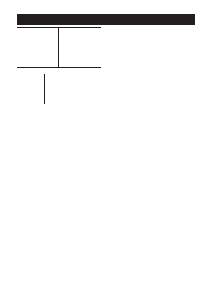
GAS BURNERS (injectors and flow-rates)
Gas Burner Injector low nominal
flow-rate flow-rate
(kW) (kW)
G20 auxiliary 70 0,40 0,90
20 semi-rapid 99 0,40 1,85
mbar rapid 126 0,85 3,00
oven 130 1,00* 3,00
grill 110 2,00
G30 auxiliary 48 0,40 0,90
28-30 semi-rapid 68 0,40 1,85
mbar rapid 86 0,85 3,00
G31 oven 86 1,00* 3,00
37 grill 70 2,00
mbar
* For thermostat. In case of oven with tap: 1.3 kW
EQUIPMENT
All models are equipped with safety device
for oven and grill burners.
Depending on the models, cooker may also
have:
- Oven thermostat (or tap)
- Electric oven lighting
- Grill burner or element
- One or more electric hotplates
For the LAYOUT OF HOB BURNERS see
the models illustrated in figure 1 at the back
of this manual.
For the ELECTRIC WIRING DIAGRAM see
figure 2 at the back of this manual.
The electrical power is stated on the nameplate visible inside the warming compartment
(if present) or on the back of the cooker.
A copy of the nameplate is glued to the cover
of this manual (for gas or gas-electric products only).
ELECTRIC HOTPLATES
ø 145 1,0 kW - Normal hotplate
1,5 kW - Rapid hotplate
ø 180 1,5 kW - Normal hotplate
2,0 kW - Rapid hotplate
ELECTRIC OVEN POWER
Oven: (1,1kW bottom
0,7kW top element) 2,2 kW
Grill: 2,0 kW
Cat.: see nameplate on cover; Class 1 or 2.1
Type “X” cookers
33
Page 4

GB
Installation
INSTALLATION
The appliance must be installed by qualified
staff working in accordance with the regulations in force.
Before installing, ensure that the appliance
is correctly preset for the local distribution
conditions (gas type and pressure).
The presettings of this appliance are indicated on the nameplate shown on the cover.
This appliance is not connected to a flue gas
extractor device. It must be installed and
connected in accordance with the regulations
in force.
This appliance may only be installed and may
only operate in rooms permanently ventilated
in accordance with national regulations in
force.
VENTILATION
The rooms in which gas appliances are installed must be well ventilated in order to allow correct gas combustion and ventilation.
The air flow necessary for combustion is at
least 2 m3/h for each kW of rated power.
POSITIONING
Remove the packaging accessories, including the films covering the chrome-plated and
stainless steel parts, from the cooker.
Position the cooker in a dry , convenient and
draft-free place. Keep at an appropriate distance from walls which may be damaged by
heat (wood, linoleum, paper, etc.).
The cooker may be free-standing (class 1)
or between two units (in class 2 st 2-1) the
sides of which must withstand a temperature of 100°C and which must not be higher
than the working table.
CONNECTING TO THE GAS SUPPLY
Before connecting the cooker, check that it
is preset for the gas to be used. Otherwise,
make the conversion as described in the
section headed “Adapting to different gas
types”. The connection is on the right; if the
pipe has to pass behind the cooker, it must
be kept low down where the temperature is
about 50°C.
- Rigid connection (see fig. 3 A + B)
The connection to the mains gas supply
may be made using a rigid metal pipe or
with a metal hose. Remove the hose connector (if already fitted) and screw the rigid
union onto the threaded connection of the
gas train (see fig. 3A). The union for rigid
connection may already be fitted on the gas
train, or may be amongst the cooker accessories. Otherwise, it can be obtained
from your dealer.
If national regulations permit, a metal hose
complying with the national standards can
be screwed directly onto the threaded connection of the gas train, fitting a seal (see
fig. 3B). However, users are strongly recommended always to fit the rigid union.
- Connection using a rubber hose (see fig.
3C). (For butane/propane gas only).
Connect a rubber hose carrying the conformity mark currently in force to the hose
connector. The hose must be replaced at
the date indicated at the latest, and must
be secured at both ends using standard hose clamps. It must be absolutely
accessible to allow its condition to be
checked along its entire length.
CAUTION:
- Use of the hose connector is only permitted for free-standing installation. If
the appliance is installed between two
class 2 st. 2-1 unions, the rigid union is
the only form of connection permitted.
IMPORTANT:
- After installation, check that the connections are airtight.
- For operation with butane/propane, check
that the gas pressure is as indicated on the
nameplate.
- Use only standard rubber hoses. For LPG,
use a hose which complies with the national
regulations in force.
- Avoid sharp bends in the pipe and keep it
well way from hot surfaces.
References to the regulations covering the
gas connection to the appliance: ISO 7-1.
34
Page 5
GB
Installation
ADAPTING TO DIFFERENT TYPES OF
GAS
If the cooker is not already preset to operate
with the type of gas available, it must be converted. Proceed as follows:
- Replace the injectors (see table on page
33);
- regulate the primary air flow;
- regulate the minimum settings.
N.B.: every time you change the type of gas,
indicate the new type of gas on the serial
number label.
REPLACING THE HOB BURNER INJECTORS (fig. 4)
- Remove the lid of the cooker by lifting it off
its supports;
- remove the grids, burner caps and burners, lifting them off;
- unscrew the 2 screws (above) or nuts (below) at the back which secure the work top,
and pull it out forward.
- remove the mixer pipes and replace the
injectors using a 7 mm socket wrench.
REPLACING THE OVEN BURNER INJECTOR (Fig. 5)
- Loosen the screw which secures the bottom of the oven;
- remove the oven bottom (pulling it forward);
- remove the oven burner, after taking out
the screw which secures it;
- replace the injector using a 7 mm socket
wrench.
REPLACING THE GRILL BURNER INJECTOR (Fig. 6)
- Remove the burner after taking out the two
screws which secure it;
- replace the injector using a 7 mm socket
wrench.
IMPORTANT:
- Never over-tighten the injectors;
- after replacing, check that all the injectors
are airtight.
REGULATING THE BURNER AIR
Refer to the table below (indicative values)
for regulation of the gap H in mm (fig. 4 for
the hob, fig. 6 for the grill).
Burner G20 20mbar G30 28-30mbar
G31 37mbar
Auxiliary 3 4
Semi-rapid 3 3
Rapid 4 6
Oven - Grill 3 8
Check operation of the burner:
- Ignite the burner at maximum flame;
- the tongue of the flame must be clear and
with no yellow tip, and must adhere closely
to the burner. If too much air is supplied,
the flame detaches from the burner and
may be dangerous. If the air supply is insufficient, the flame has a yellow tip and
soot may form.
SETTING HOB BURNER MINIMUM LEVELS
If the cooker is to work on bottled gas (butane/propane), the tap by-pass must be
screwed right down.
The cooker may be equipped with type A
taps, with by-pass inside (accessed by inserting a small screwdriver into the rod) or
type B taps, with by-pass on the outside on
the right (accessed directly). See figure 7.
If the cooker is to work on natural gas, proceed as follows for both types of tap:
- Ignite the burner at maximum flame;
- pull off the knob, without using a lever
against the control panel, which might be
damaged;
- access the by-pass with a small screwdriver
and back off by about 3 turns (turning the
screwdriver anti-clockwise);
- turn the tap rod anti-clockwise again until it
stops: the burner will be at maximum flame;
- screw the by-pass slowly back in, without
pushing the screw-driver, until the flame has
apparently shrunk to 1/4 of the maximum
size, checking that it is sufficiently stable
35
Page 6

GB
Installation
even in quite strong draughts.
SETTING OVEN BURNER MINIMUM LEVELS
If the cooker is to work on bottled gas (butane/propane), the thermostat by-pass must
be screwed right down.
If the cooker is to work on natural gas, proceed as follows:
- Remove the oven bottom (loosen the screw
to remove the bottom);
- ignite the oven burner, turning the knob
pointer to the maximum setting;
- shut the oven door;
- access the thermostat or tap by-pass (see
fig. 8);
- back off the thermostat by-pass by about 3
turns;
- after 5 or 6 minutes, turn the knob pointer
to the minimum setting;
- slowly re-tighten the by-pass, watching the
flame decrease in size through the window
in the closed oven door until the tongue of
the flame is about 4 mm long. Never keep
the flame too low. It must be stable even
when the oven door is opened or closed
quickly;
- turn off the burner and replace the oven
bottom.
CONNECTING TO THE ELECTRICAL
MAINS
Before making the connection, check that:
- the mains voltage is as indicated on the
nameplate;
- the earth connection is in good working order.
If the socket is not easily accessible, the installation engineer must provide a switch with
a contact breaking gap of 3 mm or more.
If the appliance power lead is not fitted with
a plug, use an approved standard type, remembering that:
- the green-yellow wire must be used for the
earth connection;
- the blue wire is the neutral;
- the brown wire is live;
- the lead must never touch hot surfaces over
about 75 degrees C;
- replacement leads must be of type H05RRF or H05V2V2-F of suitable size (see diagrams in fig. 2).
- if the appliance is supplied without lead,
using type H05RR-F or H05V2V2-F cable
of suitable size (see diagrams in fig. 2).
IMPORTANT: the manufacturer declines all
liability for damage due to failure to comply
with the regulations and standards in force.
Check that the appliance is correctly connected to the earth (see diagrams in fig. 2 at
the back of the manual).
THE SAFETY DEVICE
The correct gap between the end of the thermocouple sensor and the burner is shown in
figures 5 and 6.
To check that the valve is working properly,
proceed as follows:
- ignite the burner and leave it to work for
about 3 minutes;
- turn off the burner by returning the knob to
off position ( );
- after 60 seconds for oven and grill burners,
turn the knob pointer to the "on" position;
- release the knob in this position and move
a burning match towards the burner; IT
MUST NOT IGNITE.
Time needed to excite the magnet during
ignition: 10 seconds approx.
Automatic tripping time, after flame has been
turned off: not more than 60 seconds for oven
and grill burners.
IMPORTANT
- Before doing any work inside the cooker, disconnect the mains plug and shut the gas tap.
- Never use matches to check the gas circuit for leaks. If a specific control device is
not available, foam or very soapy water can
be used.
- When re-closing the hob, check that the
electrical wires of the spark plugs (if
present) are not close to the injectors, so
that they cannot run across them.
36
Page 7

GB For the user
HOW TO USE THE COOKER
VENTILATION
All gas cooking appliances produce heat and
moisture in the rooms where they are installed. Take care to ensure that the kitchen
is well ventilated; keep the ventilation openings unobstructed or install an extractor hood
with fan.
In case of intensive or prolonged use, additional ventilation may be required; open a
window, or increase the extractor fan power.
IGNITING THE HOB BURNERS
- Press the knob and turn it anti-clockwise
until it reaches the
panel (maximum flame position);
- at the same time, move a burning match
towards the burner head;
- to reduce the flame, turn the knob further
in the same direction until its pointer is
against the
sition).
IGNITING THE OVEN BURNER
- Open the oven door;
- press the knob and turn it anti-clockwise to
the maximum flame position;
- move a burning match towards the hole in
the centre of the oven bottom and press
the knob right down (see fig. 9);
- check that the burner has ignited, looking
through the hole in the centre of the bottom, keeping the knob pressed all the time;
- after about 10 seconds, release the knob
and check that the burner remains on. Otherwise, repeat the operation.
IGNITING THE GRILL BURNER (GAS
GRILLS)
- Fit the control knob guard as shown in fig.
12;
- press the oven knob and turn it to the right
until it reaches the stop;
- move a burning match towards the perforated burner pipe and press the knob right
down (see fig. 10);
symbol on the control
symbol (minimum flame po-
- check that the burner has ignited, keeping
the knob pressed down;
- after about 10 seconds, release the knob
and check that the burner remains on. Otherwise, repeat the operation.
IMPORTANT
- Difficulty in igniting burners is normal if the
cooker has been out of use for some time.
The air accumulated in the pipes will be
expelled in a few seconds;
- Never allow too much unburnt gas to flow
from the burners. If ignition is not achieved
within a relatively short time, repeat the procedure after returning the knob to the off
position (
- when the oven and grill are lit for the first
time, a smell may be noticed and smoke
may come out of the oven. This is because
of the surface treatment and oily residues
on the burners.
SAFETY DEVICE
Burners equipped with this device have the
advantage that they are protected if they
accidentally go out. If this occurs, the supply
of gas to the burner concerned is automatically cut off, preventing the hazards deriving
from a leak of unburnt gas. The gas supply
must be cut off within no more than 60 seconds for the oven and grill burners.
HOW TO USE THE HOB BURNERS
Use pans of diameter suitable for the burner
type. The flames must not project beyond
the base of the pan. Recommended sizes:
- for auxiliary burners = pans of at least 8 cm
- for semi-rapid burners = pans of at least 14 cm
- for rapid burners = pans of at least 22 cm.
N.B.: Never keep the knob at settings between the maximum flame symbol
off position
FOR COOKERS EQUIPPED WITH ELECTRIC HOTPLATES
The different heat settings are obtained as
follows:
);
and the
( ).
37
Page 8

GB
For the user
- 1 = minimum setting for all hotplates;
- 6 = maximum setting for normal and rapid
hotplates (with red disc);
- 0 = off.
Pans must never be smaller in diameter than
the hotplates and their bottoms must be as
flat as possible (see fig. 11).
IMPORTANT :
- Never leave hotplates on without pans,
except when first used; leave for about 10
minutes to dry oil or moisture residues;
- if the hotplate is to be out of use for a long time,
apply a little grease to its painted surface;
- do not allow spills to burn onto the hotplate,
requiring the use of abrasive cleaners.
HOW TO USE THE GAS OVEN
- After igniting the burner, leave the oven to
heat up for about 10 minutes;
- place the food for cooking in an ordinary oven
dish and place it on the chrome-plated shelf;
- place the food in the oven, using the shelf
on the third pair of runners whenever possible, and turn the knob pointer to the desired
setting;
- cooking can be observed through the window
in the door with the oven light on. This will
avoid opening and closing the door frequently,
unless oil or fat has to be added to the dish.
IMPORT ANT: never place foods directly on
the drip tray for cooking; it is there only to
collect any drips of fat during grilling.
N.B.: For cookers without thermostat:
- with the knob on the maximum setting
270 degrees C
- with the knob on the minimum setting
150 degrees C
- All other temperatures between 150 and
270 degrees C are obtained approximately
by positioning the knob between the maximum and minimum settings.
Never leave the knob in positions between the
maximum symbol
and the off setting
(
- ignite the burner and wait a few minutes to
allow it to warm up, or switch on the heating element;
- place the foods on the chrome-plated shelf;
- insert on the highest runner;
- insert the drip tray on the bottom runner;
- gently close the oven door, resting it against
the knob guard;
- after a few minutes, turn the food to expose
the other side to the infrared radiation (the
cooking time depends on the type of food
and personal taste).
N.B.: the first time the grill is used smoke
will come out of the oven. Before inserting
foods for cooking, wait until any oil residues
on the burner have completely burnt away.
The grill must only be used at its full rated heat.
IMPORTANT: accessible parts may be hot
when the grill is in use! Keep children well
away.
The grill element in the top of the oven is
switched on by turning the thermostat knob
clockwise to the grill symbol on the control
panel.
The red light will come on to show the element is in operation.
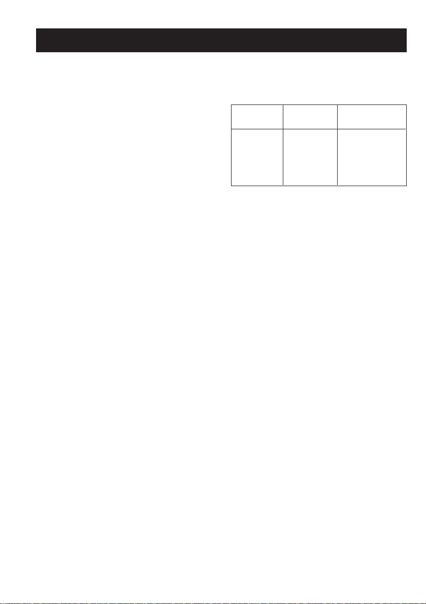
The table below will serve as a guide; bearing in mind that cooking times and temperatures may vary depending on the type and
amount of foods cooked and personal taste.
Food to be Time (minutes)
grilled 1st side 2nd side
=
Thin pieces of meat 6 4
=
).
Fairly thick pieces of
meat 8 5
Thin fish or fish
without scale 10 8
Fairly thick fish 15 12
Sausages 12 10
Toasted sandwiches 5 2
Small poultry 20 15
HOW TO USE THE GAS OR ELECTRIC
GRILL
- fit the knob guard (see fig. 12);
CONVENTIONAL ELECTRIC OVEN
- The oven shelf is designed to take normal
oven dishes for cooking sweets or roasts,
38
Page 9

GB
For the user
or is used without a pan for cooking foods
under the grill.
- The drip tray is only there to collect any juice
from foods and must never be used as a
cooking surface.
There is a single control knob for the oven
or grill.
Starting from the 0 (off) position, the knob can
be turned clockwise to the following settings:
- symbol: oven lamp on (it will remain on
even if the knob pointer is turned to the
other settings).
- Setting from 60 to 250 degrees C: oven
heat settings, with thermostat control.
- or symbol: grill on (in roof of oven)
Turn the knob anti-clockwise to return to the
0 (off) position.
N.B. - The yellow light switches on and off
as the thermostat is tripped.
Before placing food inside, allow the oven to
heat up for at least 10 minutes.
CONVENTIONAL MUL TIFUNCTION ELECTRIC OVEN
Thanks to the various heating elements controlled by a selector knob, this oven offers
several cooking modes.
Starting from the 0 (off) position and turning
the knob clockwise, the settings encountered
are:
- symbol: conventional “static” oven cooking at half power (max. temperature 120°C
approx.).
- symbol: top element on (max. temperature 155°C approx.).
-
symbol: bottom element on (max. tem-
perature 235°C approx.).
- symbol: conventional “static” oven cooking at full power (max. temperature 295°C
approx.).
-
symbol: grill on.
With all settings except zero the red light illuminates to indicate that the oven or grill is
on.
Before putting food in to be cooked, the oven
should be pre-heated for at least 10 minutes.
- The oven shelf is designed to take normal
oven dishes for cooking sweets or roasts,
or is used without a pan for cooking foods
under the grill.
- The drip tray is only there to collect any juice
from foods and must never be used as a
cooking surface.
OVENS WITH THERMOSTAT
If cooking temperatures are not as set, call
in an engineer to check the thermostat.
WARMING COMPARTMENT
T o open the warming compartment, open the
flap door with one hand (see figure 13).
To close the warming compartment, simply
press the flap door back into place.
GENERAL PRECAUTIONS
- Always disconnect the power supply before
any work inside the oven or where live parts
may be accessed.
- Never use the warming compartment for
storing inflammable liquids or items which
do not withstand heat, such as wood, paper, aerosol cans, matches, etc.
- Make frequent checks on the rubber connection hose, ensuring that it is well away
from hot surfaces, that there are no sharp
bends or kinks, and that it is in good condition. The hose must be replaced at the latest at the indicated date and must be secured at both ends using a standard hose
clamp.
- If taps become stiff to operate over time,
contact the After-Sales service.
- Wash enamelled or chrome-plated parts
with soapy lukewarm water or non-abrasive
detergents. A metal brush may be used to
remove deposits from hob burners and
flame caps. Dry thoroughly.
- Never use abrasives to clean enamelled or
chrome-plated parts.
- Do not use too much water when washing
the hob. Take care that no water or other
substances enter the burner housing holes,
as this may be dangerous.
39
Page 10

GB For the user
- The spark plugs for electric ignition must
be kept clean and dry; always check after
use, particularly if there have been drips or
overflows from pans.
- Never close glass lids until the hob burners or hotplates have cooled completely; it
might shatter or crack.
- Never knock enamelled parts or ignition
spark plugs (where present).
- The main or wall gas tap should be turned
off when the cooker is not in use.
- Never lift the cooker by taking hold of the
oven door handle.
No liability is accepted for injury or damage
caused by poor installation or improper use
of the cooker.
In case of malfunctions, particularly gas
leaks or short-circuits, contact your engineer without delay.
40
Page 11

Figuras / Figures / Figuras / Figures
CUADRO DE CONEXIONES
SCHEMA DES BRANCHEMENTS
SR
ESQUEMA DE LIGAÇÃO
CONNECTION DIAGRAM
A = AUXILIAR
= AUXILIAIRE
= AUXILIAR
= AUXILIARY
A
SR
A
P1 SR
A
SR
SR = SEMIRRÁPIDO
R
R
R
= SEMI-RAPIDE
= SEMI-RÁPIDO
= SEMI-RAPID
230 V BIFASICO / BIPHASE / BIFÁSICO / TWO-PHASE
400 V MONOFASICO + NEUTRO / MONOPHASE + NEUTRE /
MONOFÁSICO + NEUTRO / SINGLE-PHASE + NEUTRAL
13452
L
230 V TRIFASICO / TRIPHASE / TRIFÁSICO / THREE-PHASE
N
13452
LLL
400 V TRIFASICO + NEUTRO / TRIPHASE + NEUTRE /
TRIFÁSICO + NEUTRO / THREE-PHASE + NEUTRAL
13452
L
LN
L
Sección cable
Section câble
Sec. cabo
Wire gauge:
3x6 mm
Sección cable
Section câble
Sec. cabo
Wire gauge:
4x4 mm
Sección cable
Section câble
Sec. cabo
Wire gauge:
5x2,5 mm
2
2
2
R = RÁPIDO
= RAPIDE
= RÁPIDO
= RAPID
P1 = PLACA Ø 180
= PLAQUE Ø 180
= DISCO Ø 180
= HOTPLATE Ø 180
P2 = PLACA Ø 145
= PLAQUE Ø 145
= DISCO Ø 145
= HOTPLATE Ø 145
230 V BIFASICO / BIPHASE / BIFÁSICO / TWO-PHASE
12
LN
> 3,5 kW 3x2,5 mm
2,2 - 3,5 kW 3x1,5 mm
0 - 2,2 kW 3x1 mm
1
Sección cable
Section câble
Sec. cabo
Wire gauge:
2
2
2
2
41
Page 12

Figuras / Figures / Figuras / Figures
A
C D
B
1,5 mm
2 mm
4 mm
AB
TERMOPAR
A =
THERMOCOUPLE
B = BUJÍA / BOUGIE D'ALLUMAGE / VELA DE IGNIÇÃO /
SPARK PLUG
/ THERMOCOUPLE /
TERMOPAR
/
5
B
H
TERMOPAR
A =
THERMOCOUPLE
B = BUJÍA DE ENCENDIDO / BOUGIE D'ALLUMAGE /
VELA DE IGNIÇÃO / SPARK PLUG
/ THERMOCOUPLE /
A
TERMOPAR
mm 3 mm 3
/
mm 3
mm 2 - 4
B
A
H
A = TERMOPAR / THERMOCOUPLE / TERMOP AR /
THERMO-COUPLE
B = BUJÍA / BOUGIE / VELA / SPARK PLUG
3
6
7
4
8
42
Page 13

9
10
Figuras / Figures / Figuras / Figures
13
11
12
43
Page 14

ED. 09.02.1999 334813
B1/44
 Loading...