

IO-123078 Effective 12-01-11
7
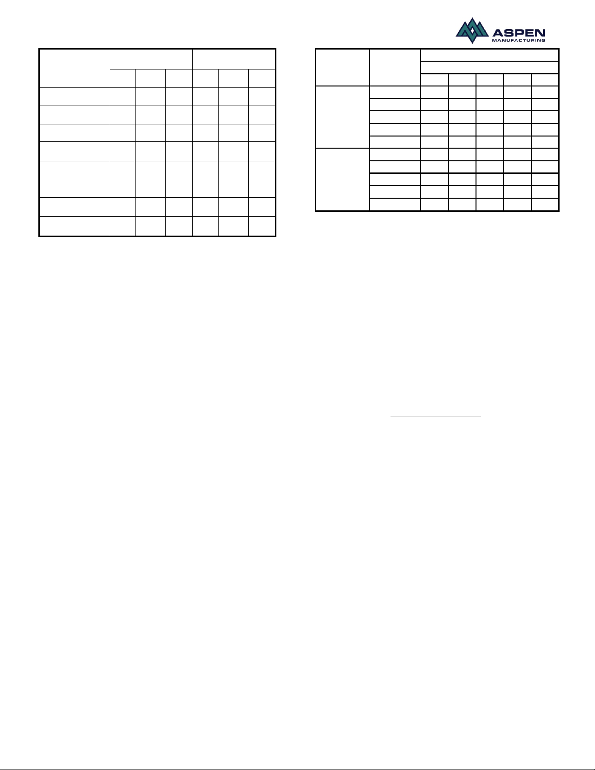
Outdoor Temp
°F D.B.
Superheat °F
Subcooling °F
Min
Nom
Max
Min
Nom
Max
65
35
40
45
12
14
15
70
31
35
39
12
14
15
75
26
30
34
12
14
15
80
22
25
28
12
14
15
85
17
20
23
12
14
15
90
13
15
17
12
14
15
95
8
10
12
12
14
15
100
4 5 6
12
14
15
Table.2. Superheat and Subcool chart
Start up
After all connections are made, start-up and check-up
must be performed before proper evaluation of the entire
system can be made. Make sure that heat anticipator is
properly set as noted on thermostat instructions.
Load requirements can vary in each residence and it
may be necessary for the installer or homeowner to
make slight adjustments to the heat anticipator setting
for longer or shorter cycles. It is recommended to
change the setting no more than plus or minus 0.05
amps at a time. Greater changes can cause the unit to
rapid cycle or remain on excessively. To properly check
the unit's operation, the installer should have an
electrical current measuring device (0-10 amp Amprobe,
Fluke), air pressure measuring device (0-1.0 in slope
gauge), and a temperature-measuring device (0-200ºF
thermometer).
Install the Amprobe to measure blower current, the slope
gauge to measure static air pressure at the units and the
temperature device to measure unit supply and return air
temperature. Before taking measurements, be sure that
all registers, grilles and dampers are open or set to their
proper positions. Be sure that clean filters are in place.
Temperature measuring device must be installed to
obtain average temperature at both inlet and outlet. For
outlet, measure temperature of each main trunk at a
location far enough away to avoid heater radiation and
read the average temperatures. Table 3 below shows
the CFM that should be achieved at various external
static pressures
0.10 0.20 0.30 0.40 0.50
Tap 5 909 864 840 800 782
Tap 4 723 690 652 631 600
Tap 3 600 565 539 502 480
Tap 2 909 864 840 800 782
Tap 1 723 690 652 631 600
Tap 5 1365 1332 1303 1271 1240
Tap 4 1174 1132 1106 1078 1047
Tap 3 898 873 853 827 800
Tap 2 745 698 668 630 600
Tap 1 1365 1332 1303 1271 1240
AEW18-24
AEW30-36
SPEED
TAP
MODELS
230 Volt
CFM V. EXTERNAL STATIC
Table 3. CFM delivered at various external statics
Electrical H eat Controls:
• Turn on power supply. Set thermostat fan switch to
on. Set the cooling indicator to maximum, heating to
minimum. System switch may be on heat or cool.
Check slope gauge measurement against
appropriate air flow chart. Make damper, register
and motor speed adjustments to obtain required
airflow.
• Set thermostat fan switch to auto, system to heat
and thermostat heating indicator to maximum heat.
Blower should start and all heat be energized.
• Check air flow using temperature rise method.
( )
RISETEMP
BTUHOUTPUT
CFM×=
08.1
NOTE: BTUH output should be computed by VOLT x
AMPS x 3.4 = BTUH OUTPUT. Since line volt can vary,
do not use nameplate rating to determine output.
OPERATION AND MAINTENANCE
Below are brief descriptions of the key components of
the unit and installation. This manual only provides a
general idea of the components and recommended
practices. The installer should use best judgement to
ensure safe installation and operation of the unit.
1) Room Thermostat- This is the device that controls
that operation of your heating and/or cooling unit. It
senses the indoor temperature and signals the
equipment to start or stop maintaining the
temperature you have selected for your comfort. The
room thermostat should be in a central, draft free
inside wall location for best operation. Do not place
any heat producing apparatus such as lights, radio,
etc., near the thermostat as this will cause erratic
operation of the comfort system. The thermostat can
accumulate dust or lint which can affect its accuracy.
It should be cleaned annually.
IO-123078 Effective 12-01-11
8
2) Air Filter(s) - All central air moving comfort systems
must include air filter(s). These filters will be located
either in the equipment or in the return air duct
system upstream of the equipment. The filter(s)
removes dust and debris from the air thus helping to
keep your air-conditioned space clean. More
important, the filter keeps dust and debris from
collecting on the heat transfer surfaces thus
maintaining optimum equipment efficiency and
performance. Inspect and clean or replace filters
every month. This routine maintenance procedure
will pay big dividends in reduced operating cost and
reduced service expense. Never operate comfort
equipment without filter(s).
3) Fuses and/or Circuit Breakers- This comfort
equipment should be connected to the building
electric service in accordance with local and
National Electric codes. This electrical connection
will include over-current protection in the form of
circuit breakers. Have your contractor identify the
circuits and the location of over-current protection so
that you will be in a position to make inspections or
replacements in the event the equipment fails to
operate.
4)
WARNING
a) Do not store combustible materials or use
gasoline or other flammable liquids or vapors in
the vicinity of this appliance.
b) Do not operate the comfort equipment with
panels removed.
c) Have your contractor point out and identify the
various cut-off devices, switches, etc., that serve
your comfort equipment. There is a main switch
that will cut off energy to your heating system.
Know where they are so that you may cut off the
flow of energy in the event of overheating.
5) Periodic Checkup and Service- This product is
designed to provide many years of dependable,
trouble-free comfort when properly maintained.
Proper maintenance will consist of annual check-ups
and cleaning of the internal electrical and heat
transfer components by a qualified service
technician. Failure to provide periodic checkup and
cleaning can result in excessive operating cost
and/or equipment malfunction.
6) Lubrication- Direct drive blower motors are equipped
with permanently lubricated bearings and do not
require further lubrication.
7) Air filter replacement: An air filter can restrict the
airflow to the fan coil if it is not cleaned or replaced
periodically. When replacing the air filter, always
replace with the same type and size as originally
furnished with the unit.

IO-123078 Effective 12-01-11
9
Wiring diagram for AEW models
HIGH VOLTAGE disconnect all power sources prior to servicing. Failure might lead to safety hazard
 Loading...