

INSTALLATION GUIDE
AEW & AAW Series - Vertical Wall Mount
Air Handler (Electric Heat)
1. Safety Instruction
Potential safety hazards are alerted using the following symbols. The symbol is used in conjunction with terms
that indicate the intensity of the hazard.
`
WARNING
!
This symbol indicates a potentially hazardous situation, which if not avoided,
could result in serious injury, property damage, product damage or death.
CAUTION
!
Certied technicians or those individuals
WARNING
!
and product damage or personal injury hazard may occur
without such background.
WARNING
!
WARNING
!
installer’s responsibility to ensure that product is installed
in strict compliance with national and local codes. Manufacturer takes no responsibility for damage (personal, product
or property) caused due to installations violating regulations. In absence of local/state codes, refer to National Electric Code: NFPA 90A & 90B Uniform Mechanical Code.
WARNING
!
(i.e. automobile, space heater, water heater etc.) ensure that
the enclosed area is properly ventilated.
CAUTION
!
these instructions. Some localities may require a licensed
installer/service personnel.
WARNING
!
WARNING
!
damages caused due to modication of the unit to operate
with alternative power sources.
# 123106
meeting the requirements specied by
NATE may use this information. Property
All power sources should be disconnected prior to servicing. Failure to do so may
cause personal injury or property dam-
age.
Product designed and manufactured to
permit installation in accordance with local and national building codes. It is the
When this unit is installed in an enclosed
area, such as a garage or utility room with
any Carbon Monoxide producing devices
Only factory authorized kits and accessories should be used when installing or
modifying this unit unless it is so noted in
Unit is not approved for outdoor installations.
The unit is designed for operation with
208/240 V, single phase, 60 Hz power
supply. Aspen will not be responsible for
This symbol indicates a potentially hazardous situation, which if not avoided,
may result in moderate injury or property damage.
2. Introduction
The AEW/AAW Series air handlers are versatile upow only models
that can be recess mounted or ush mounted onto walls. These air
handlers have the following standard features:
I. Application Versatility
Front or bottom return air position. Offset hanging brackets attach to
unit and wall to allow hanging inside closet.
Can be ARI matched with most brands of air conditioners or heat
pumps for use with either R22 or R410a when proper metering device is used.
II. Motor
AEW models: Constant torque ECM speeds and torques are controlled by software embedded in the motor to maintain constant
torque. Motors are pre-programmed at the factory.
AAW models: Dual speed PSC motor.
III. Cabinet
Sturdy, short galvanized steel cabinet with painted front panels. Cabinet fully insulated with 1/2” faced insulation to prevent sweating and
mold growth, to encapsulate glass bers, and to provide excellent
R-value. Stick pins ensure insulation remains in place.
Units ship with disposable lter in lter rack.
IV. Modular Electric Heat Kits
Heat kits available with either circuit breakers or terminal blocks.
Available in 3, 5, 8, & 10 KW. Models with electric heat include se-
quencers and temperature limit switches for safe, efcient operation.
Modules are easily installed in the eld using molex plugs or can be
ordered factory-installed. Controls are accessible from the front for
easy service.
Electrical connections can be made from the top or left. Disconnect
does not protrude through the wall panel.
Fan time delay relay standard for increased efciency.
V. Blower
Direct drive multi-speed blowers circulate air quietly and efciently.
Motor speeds can be easily selected via motor terminals. Swing
mounted blowers can be easily removed for service.
VI. Electronic Circuit Board
Electronic circuit board provides 30 sec. ON/OFF blower time delay
extracting more heat/cool from the coil
1
VII. DX Coil
High efciency ried copper tubes/enhanced aluminum ns provide
maximum heat transfer. All coils immersion tested at 500 psi then
nitrogen pressurized and factory sealed for maximum reliability. Coil
mounted Schrader allows pre-installation pressure testing.
Available with either check style owrater or TXV metering device.
Field-installable TXVs are also available.
Galvanized metal drain pan with bottom primary and secondary
drain connections or alternate right side primary. All connections 3/4”
FPT. Access door allows for coil cleaning.
VIII. Warranty
Five year limited parts warranty.
3. Inspection
ü On receiving the product, visually inspect it for any major shipping
related damages. Shipping damages are the carrier’s responsibility.
Inspect the product labels to verify the model number and options
are in accordance with your order. Manufacturer will not accept damage claims for incorrectly shipped product.
4. Installation Preparation
Read all the instructions in this guideline carefully while paying special attention to the WARNING and CAUTION alerts. If any of the
instructions are unclear; clarify with certied technicians. Gather all
the tools needed for successful installation of the unit prior to beginning the installation.
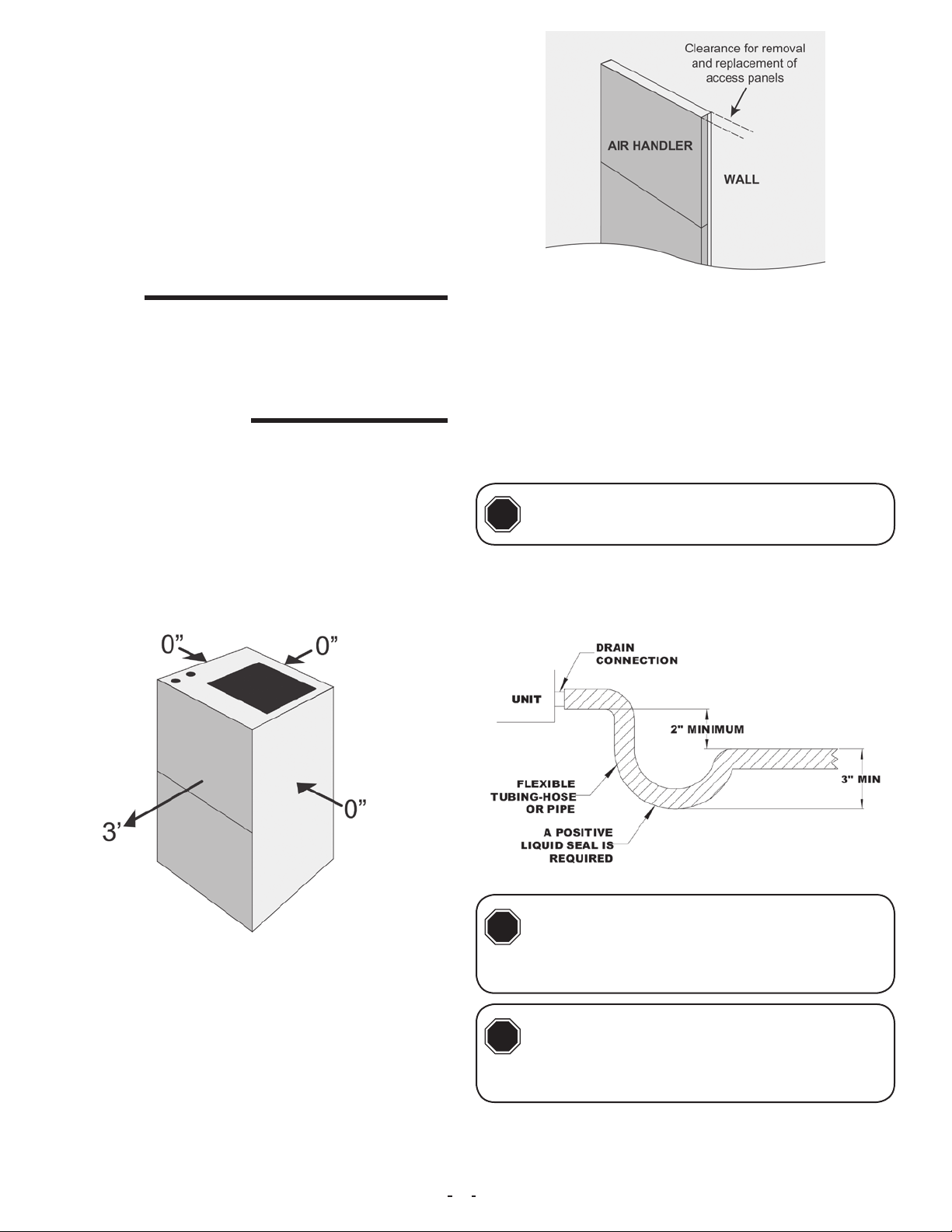
4A. Clearances
This unit is designed for zero clearance installation on three sides
and adequate clearance to provide access for service in the front.
A minimum of 2.5 – 3.5 feet clearance is recommended on the front
end (Fig 4A-1).
4C. Condensate Drain Preparation
ü An auxiliary drain pan must be provided by the installer and placed
under the entire unit with a separate drain line that is properly sloped
and terminated in an area visible to the home owner. The auxiliary
pans provide extra protection to the area under the unit should the
primary and secondary drain plug up and overow. As expressed
in our product warranty; ASPEN WILL NOT BE BILLED FOR ANY
STRUCTURAL DAMAGES CAUSE BY FAILURE TO FOLLOW
THIS INSTALLATION REQUIREMENT. The drains from the auxil-
iary drain pan must be installed according to the local building codes.
4D. Condensate Drain
Drain lines from the auxiliary drain pan
CAUTION
!
The drain lines must be installed with ¼” per foot pitch to provide free
drainage. A condensate trap MUST be installed on the primary drain
line to ensure proper drainage of the condensate. The trap must be
installed in the drain line below the bottom of the drain pan (Fig.
4C-1)
should NOT be connected to the primary
drain line of the coil.
Fig 4A-1. Minimum Clearance for Air Handler
4B. Recess Mounting or Wall Mounting Option
These units are designed to be installed in a small room where they
can be mounted above a water heater or recessed into a wall. The
unit should be installed in Vertical Upow position ONLY.
If installing the air handler into a recessed wall, the unit must leave
clearance to allow the removal of the front panels. The bottom of the
unit should also rest on a sturdy platform or oor. The unit must be
level to allow condensate drainage.
These air handlers come with an offset mounting bracket that at-
taches the air handler to the wall when the unit is ush mounted to
the wall.
Fig 4C-1. Condensate Drain Trap
Since coil is upstream of the blower, all
CAUTION
!
from the drain pan. Aspen will NOT be responsible for any
damages resulting from failure to follow these instructions.
CAUTION
!
DO NOT USE SOLVENT BASED PIPE DOPE. THIS WILL REDUCE THE LIFE OF THE PAN.
The drain pan has primary (white) and secondary (red) drain connections. If a secondary drain line is required, it should be run separately
from the primary and should terminate in a highly visible location.
Condensate disposal through the secondary drain line indicates that
2
drains MUST be trapped or sealed. Failure
to do so will result in condensate overow
If the drain pan is constructed of nylon
or plastic; use Teon tape to connect the
drain lines to the threads in the drain pan.
# 123106

the primary drain line is plugged and needs cleaning. If a secondary drain line will not be provided, plug the secondary drain. Drain
plugs are NOT to be reused without plumbers tape or putty. Drain
line connection should be nger tightened, then turned no more than
one complete turn as needed to ensure a rm connection. DO NOT
overtighten connection or damage may occur.
4E. Ductwork
Duct systems should be installed in accordance with standards for
air-conditioning systems, National Fire Protection Association Pamphlet No. 90A or 90B. They should be sized in accordance with National Environmental System Contractors Association
Manual K, or whichever is
applicable.
On any job, non-ammable
exible collars should be
used for the return air and
discharge connections to
prevent transmission of vibration (Fig 4E-1). Although
these units have been specially designed for quiet
vibration-free operation,
air ducts can act as soundboards, can, if poorly installed, amplify the slightest
vibration to the annoyance
level.
All main supply and return air drops should be properly sized as
determined by the designer of the duct system and should not nec-
essarily be the size of the duct ange openings of the unit. (The
duct size should never be smaller than the ange openings of the air
handler supply and return air openings.)
These models have a bottom or front return. Discard the drain ac-
cess panel in the bottom of the unit if this is a bottom return application (Fig 4E-2). In case of a front return application, the front access
panel should be removed and discarded.
Fig 4E-2.
If an accessory grill is being used, the front access panel should be
removed and discarded (Fig 4E-3).
Fig 4E-1.
A lter rack is provided for a 1”X20”X20” (AAW/AEW18/24/30/36/31/37)
or 1”X14”X18” (AAW/AEW19/20/25/26) nominal size lter (Fig 4E-4).
Inspect and clean or replace iter every month. A blocked lter can
reduce air ow to the coil and hinder the performance of the system.
Fig 4E-4.
It is recommended that wherever supply and return air sheet metal
ducts pass through unconditioned areas, they be insulated to pre-
vent excessive heat loss during heating operation. When applied in
conjunction with summer air conditioning, sheet metal duct routed
through unconditioned areas should be insulated and have an outside vapor barrier to prevent formation of condensation.
5. Installation
Ensure that the unit is adequately sized.
CAUTION
!
WARNING
!
to installation. If holding pressure is not present, return coil
to distributor for exchange.
CAUTION
!
present) are protected from heat during brazing and installation to prevent leakage. Use a core removal tool to temporarily remove the core when brazing. Replace the core once
brazing is completed.
CAUTION
!
ü Clean coil ns with degreasing agent or mild detergent and rinse
ns clean prior to installation.
The tonnage of the outdoor unit should
never exceed the tonnage of this unit.
The coil was manufactured with a dry nitrogen pre-charge. Release the pressure
through the Schrader valve test port prior
Some Aspen coils may include a Schrader
valve on the suction manifold. Ensure that
the Schrader valve and valve core (where
Insulation on the suction line MUST extend
into the cabinet and continue as far as
possible to eliminate condensate dripping
onto the access door.
# 123106
Fig 4E-3.
ü The refrigerant line sizes should be selected according to the recommendations of the outdoor unit manufacturer.
ü Care must be taken to ensure all connection joints are burr-free
and clean. Failure to do so may increase chances of a leak. It is
recommended to use a pipe cutter to remove the spun closed end of
the suction line.
ü To reduce air leakage, rubber gommets may be present where the
lines pass through the coil case. To avoid damage, remove grommets prior to brazing by sliding over the lines. Use a quenching cloth
or allow the lines to cool before reinstalling the grommets.
ü Use of wet rags/quenching cloth is highly recommended to prevent
weld-related damages to the casing and Schrader valve (if present).
3
6. Mounting Air Handler To Wall
1. Install the air handler in a level position side to side and front to
back. If this step is not followed, condensate water damage may oc-
cur. (Both ush mount and recess mount congurations.)
2. Determine where the air handler is to be placed on the wall.
Place the hanging bracket on the
wall and align the holes of the
bracket with the wall studs. Level
the hanging bracket and mark the
holes to drill pilot holes for the
screws.
3. Drill the pilot holes.
4. Secure the bracket with
screws sufcient to hold 4X the
weight of the air handler.
5. Position the air handler on the
wall with the bracket on the air
handler slightly higher than the
bracket secured on the wall.
Lower the air handler so that the
brackets engage. Check the unit
for level, both side to side and
front to back.
CAUTION
!
ing to the capacity of the outdoor unit.
WARNING
!
Use Piston sizes recommended by the
outdoor unit manufacturer whenever possible. The piston should be sized accord-
Failure to install the proper piston can
lead to poor system performance and
possible compressor damage.
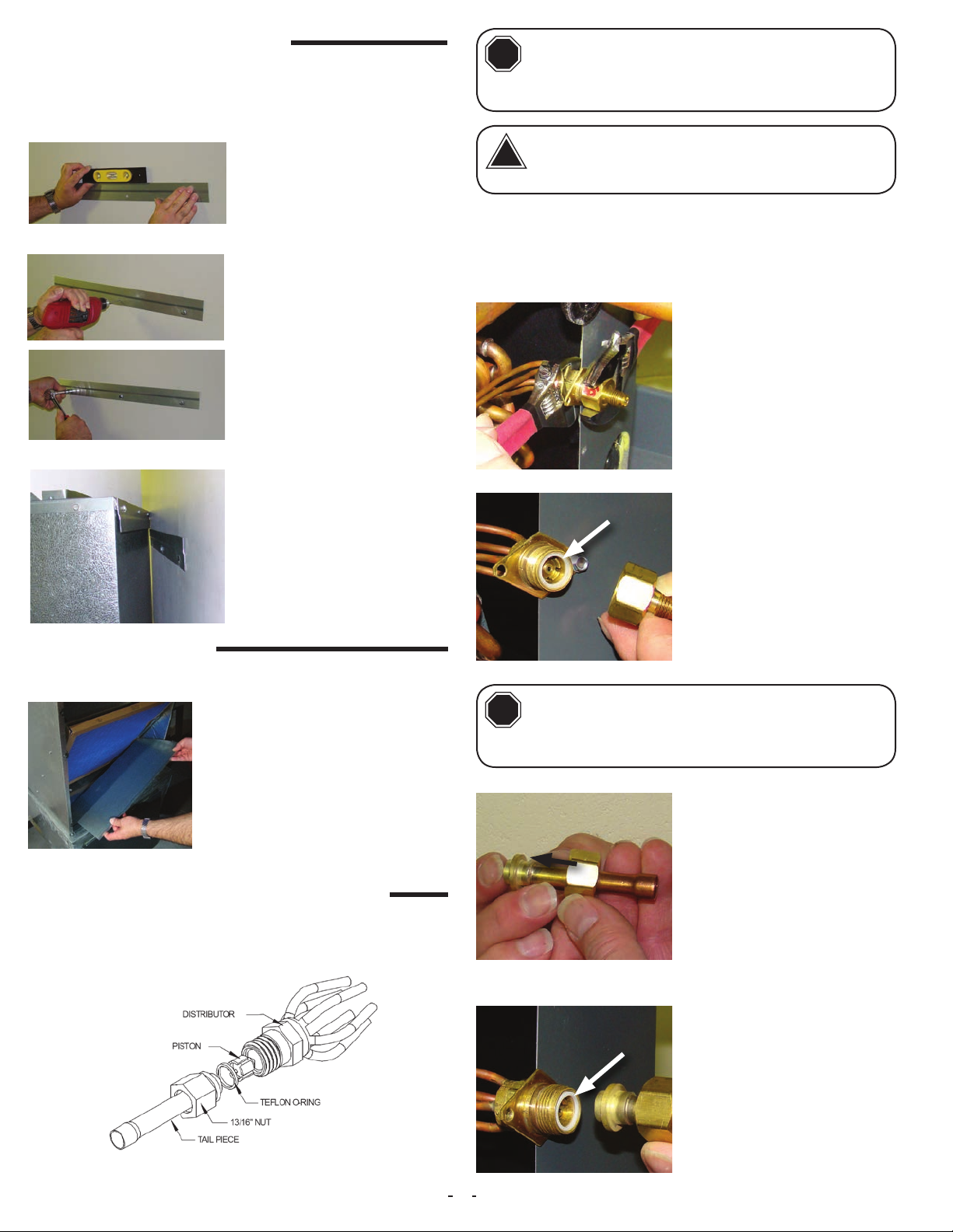
I. Installation
Note: Photos are for basic illustration purposes only. Actual equip-
ment conguration may differ from that shown.
I-1. Disassemble owrator body
using two wrenches and unscrewing with a counterclockwise
motion.
O-ring
I-2. Replace the Teon O-ring
(located between the halves).
Discard Schrader if present.
7. Connecting Ducting
1. Secure supply air ducting to the top of the air handler. Canvas connectors are recommended for reducing potential noise transmission.
2. If the bottom return air opening is
being used, remove the bottom panel. If a front return is being used, this
panel will remain in place.
3. Secure the return air ducting to the air handler cabinet.
8. Metering Devices/Liquid Line Connection
Aspen coils are available with two kinds of metering devices a) owrator or b) TXV. The following instructions are separated into sec-
tions by metering device.
8A. Flowrator Coils
CAUTION
!
I-4. Braze the stub-out portion to the liquid line and let cool.
Be aware of the Teon O-ring. Be sure to
replace the O-ring to attain a proper
seal. (The Teon O-ring is located between
the two halves of the owrator)
I-3. Slide the attachment nut onto
the liquid line stub out.
O-ring
I-5. Taking care that the white
Teon seal is still in place inside
the owrater body, rmly seat the
stub and screw the attachment
nut to owrater body.
Fig 7A-1. Flowrator assembly components
4
# 123106
I-6. Tighten the nut to a torque of approximately 10-30 ft-lbs. Do NOT
overtighten the nut. Overtightening will impede the piston movement
during operation.
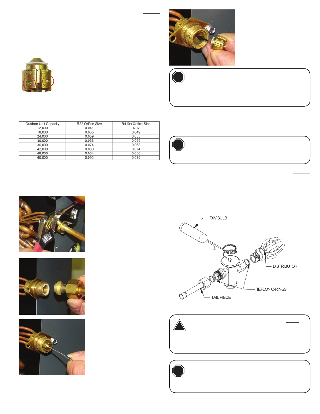
II. Piston Replacement
Note: Photos are for basic illustration purposes only. Actual equip-
ment conguration may differ from that shown.
During some installations, a piston change may
be required. If so, the installer MUST change the
piston. Use piston sizes recommended by the
outdoor unit manufacturer. If a sizing chart is not
available, use the piston size chart provided below to size the required piston. The size of the
Fig 8A-2
Use the chart below when matching coil with an outdoor unit with a
different nominal capacity than the coil.
piston is stamped on the piston body (Fig 8A-2).
II-6. Replace the piston with one
of the correct size. Do not force
the new piston into the body.
Make sure the piston moves
freely in body.
CAUTION
!
coil. Failure to ensure this orientation will cause the piston
to be bypassed during operation which might damage the
outdoor unit.
II-7. Assemble the two halves correctly and ensure that the white
Teon O-ring is present between the two halves (See I-5). Slide the
13/16” nut onto the distributor body.
Pay close attention to the piston orientation. The pointed end of the piston MUST
go into the distributor body, towards the
II-1. Evacuate the system as per manufacturer guidelines and rec-
ommendations
II-2. Turn the 13/16” nut once to release any residual pressure in the
coil.
II-3. After ensuring that the coil
is free of any residual pressure,
disassemble the owrator body
completely using two wrenches.
Take great care not to distort the
feeder tubes. The wrench used
to clasp the nut should be turned
in counter-clockwise direction to
unscrew the nut.
II-4. Slide the 13/16” nut over
the lineset and separate the two
halves of the owrator.
CAUTION
!
II-8. Tighten the nut to a torque of approximately 10-30 ft-lbs. Do NOT
overtighten the nut. Overtightening will impede the piston movement
during operation.
II-9. If present, slide the rubber grommet back to position to prevent
air leakage.
Be aware of the Teon O-ring. Be sure to
replace the O-ring to attain a proper
seal. (The Teon O-ring is located between
the two halves of the owrator)
7B. TXV Coils
# 123106
II-5. Pull the piston out using a
small wire or pick. Verify the piston size (size is typically stamped
on the body of the piston - Fig
8A-2). If a different piston size
is required by the outdoor unit
manufacturer, replace the piston
using the small wire provided with
the piston kit.
Fig 8B-1. Components of a typical TXV assembly
The sensing bulb and TXV body MUST be
WARNING
!
be covered using a quench cloth or wet cloth when brazing.
Pointing the brazing ame away from the valve and sensing
bulb provide partial protection only.
CAUTION
!
painted green for R22 or pink for R410A. In absence of color, the caps will be marked with the compatible refrigerant.
protected from overheating during brazing. The sensing bulb and TXV body must
Ensure that the TXV selected is compatible with the refrigerant used in the outdoor system (R22 or R410A). TXV caps are
5

The valves should be sized according to
CAUTION
!
formance and possible compressor damage.
the capacity of the outdoor unit. Failure to
install the right valve can lead to poor per-
I. TXV Bulb Horizontal Mounting
The orientation and location of the TXV bulb has a major inuence
on the system performance.
Ensure that the TXV bulb is in direct con-
CAUTION
!
ed. Failure to do so will impair the proper functioning of the
TXV valve.
It is recommended that the TXV bulb be installed parallel to the
ground (on a horizontal plane). The bulb position should be at
2 o’clock or 10 o’clock. Fig. 7B-2 shows the recommended position
for the TXV bulb installation in the horizontal plane.
tact with the suction/vapor line. Gap between the bulb and tube should be avoid-
II. TXV Bulb Vertical Mounting
As recommended in Section
8B-I, the TXV sensing bulb
should be mounted in a horizontal plane in relation to the
suction/vapor line. However,
some installation congurations may require that the
sensing bulb be mounted vertically. In this instance, place
the bulb opposite the piping
wall being hit by refrigerant
and oil leaving the distributor
tubes, and with capillary tubes
directed upwards as shown in
Fig. 8B-3.
Fig 8B-3. Recommended location
for vertical TXV bulb mount
If the TXV sensing bulb is mounted verti-
CAUTION
!
wall opposite to that being directly hit by the refrigerant and
oil leaving the distributor tubes.
cally; the capillary MUST be directed upwards. The bulb must be mounted on the
Bulb position at
2 o’clock or
10 o’clock
Fig 7B-2. Recommended location for horizontal TXV bulb mount
The TXV sensing bulb SHOULD be mounted on the suction line approximately 6” from the TXV or coil housing using the metal clamp
provided. In order to obtain a good temperature reading and correct
superheat control, the TXV sensing bulb must conform to ALL of the
following criteria:
1. The sensing bulb MUST be in direct and continuous
contact with the suction line.
2. The sensing bulb should be mounted horizontally on
the suction line.
3. The sensing bulb MUST be mounted at the 2 o’clock or
10 o’clock position on the circumference of the suction line.
4. The sensing bulb MUST be insulated from outside air.
A properly mounted sensing bulb will prevent false readings caused
by liquid refrigerant that may have formed inside the suction/vapor
line. Insulation will protect the sensing bulb from false readings due
to contact with warm air.
III. Field-Installed TXV Retrot
Note: Photos are for basic illustration purposes only. Actual equip-
ment conguration may differ from that shown.
When installing an expansion valve, it is not necessary to slide the
coil out of the housing.
III-1. Disassemble the owrator
body using two wrenches. Unscrew the body with a counterclockwise motion.
III-2. Remove the existing ow-
rator piston using a small wire
or pick.
III-3. Replace the Teon O-ring
seal in place (located between
the halves).
O-ring
6
# 123106

III-4. Inspect the TXV box to conrm that the valve is compatible
with the refrigerant in the system.
Male
(Inlet)
Female
(Outlet)
III-5. Remove the valve from
the box and note the location of the inlet side (threaded
male port) and the outlet side
(female swivel nut port).
III-6. After ensuring that the
Teon O-ring seal is still in place
inside the owrator body, screw
the female swivel nut onto the
owrator body.
O-ring
III-7. Slide attachment the nut onto the liquid line stub out
(See 8A, I-3)
III-8. Braze the stub-out portion to the liquid line and let cool.
WARNING
!
Do not attempt to touch brazed joints
while hot. Severe burns may result.
B. Screw are nut on TXV equal-
ization tube on to the Schrader
valve stem.
III-12b. In some cases, a suction line schrader port may not be
present. If a Schrader port is NOT present:
A. Install a eld-supplied braze-on schrader
valve like that shown on the suction line near the
intended sensing bulb mounting location. Follow valve manufacturer instructions and recommendations for installation.
B. Attach equalizer tube to valve as described in
section III-12a above.
III-13. Mount the sensing bulb as described in section 8B-I or 8B-II.
When handling or manipulating the equal-
!
CAUTION
izer tube, take great care not to kink or
make extreme bends in the tubing.
O-ring
III-10. Tighten all connections taking care to use proper back up.
III-11. Remove the valve identication sticker from the valve and
place it adjacent to the Aspen model number on unit name plate.
III-12a. Some Aspen coils come with a Schrader valve on the suction line. If a Schrader port is present:
III-9. Remove the additional Tef-
lon O-ring seal from the box and
place on the shoulder just inside
the TXV inlet port. Screw the nut
attached to the stub-out portion of
the owrator body onto the inlet
port of the TXV.
A. Remove the valve stem from
the Schrader port mounted on the
suction line.
# 123106
7

9. Connecting Refrigerant Lines
1. Release nitrogen holding charge by depressing the
Shrader Valve at the liquid line
connection on the air handler.
If no gas releases from the air
handler, contact distributor regarding potential leak.
2. Cut off Shrader Valve tting at
the liquid line connection. Use a
tubing cutter for this step. Clean
the burr from the cut tubing to
reduce the chance of future
leaks. Connect the liquid line to
the tubing at the indoor unit.
7. Flow nitrogen through the piping when brazing.
8. Braze both refrigerant line connections using proper brazing procedures.
9. When all line connections are brazed, perform a proper system
evacuation procedure per the outdoor unit manufacturer instructions.
10. Seal the penetration openings where the lineset piping enters the air handler cabinet.
10. Leak Check
1. Following outdoor unit manufacturer instructions and recommen-
dations, charge the system with dry nitrogen to a maximum pressure
of 150 PSIG.
3. Use a tubing cutter to remove
the spun end from the suction
line connection at the air handler. Clean the burr from the cut
tubing to reduce the chance of
future leaks.
4. To avoid heat damage to grommets where present, remove these
prior to brazing by sliding them over the refrigerant lines and out of
the way.
5. Check to determine if the
evaporator coil has a Shrader
tting on the suction manifold.
If yes, remove the valve core
to prevent heat damage during
brazing. Replace the valve core
once the piping has cooled.
2. Check all brazed and screwon line connections by applying a
soap solution to the joint. A leak
will produce bubbles in the soap
solution.
3. If any leaks or are discovered, relieve system pressure and repair
leaks. Repeat steps 1-3.
4. With no leaks or weak connections present, evacuate the system
and charge as per the outdoor unit manufacturer instructions and
specications.
11. Electrical Line Voltage Wiring
These units are designed for single or three phase 208/240 volts, 60
HZ power supply. Wire selection and wiring must be in accordance
with the National Electric Code and/or local codes. Unit terminals are
designed to accommodate copper and aluminum wiring. If aluminum
wiring is used: please observe special precautions relative to sizing,
wire connections and corrosion protection.
All models with 5,8 or 10 kW electric heat are arranged for single
circuit connections. Models larger than 10 kW are arranged for multicircuit protection. Refer to top part of wiring diagram at the end of this
guide for detailed information.
6. If the air handler has a TXV
metering device, remove the
sensing bulb from the suction
line prior to brazing to prevent
heat damage from occurring.
Replace the sensing bulb once
the piping has cooled.
8
# 123106

Line voltage wiring should be
routed through the access holes
at the top of the air handler.
Proper electrical conduit con-
nection ttings should be used.
Connect the power wiring to the
line side connections on the air
handler. The electrical ground
wire should be connected to the
grounding lug. Ensure both the
eld supplied ground wire and
air handler GREEN ground wire
are both secured to the grounding lug of the air handler.
240VAC
Tap
208VAC
Tap
If the line voltage being supplied
to the air handler is 208 volt single phase, the line voltage tap
on the low voltage transformer
needs to be moved from the 240
volt tap to the 208 volt tap. If this
is not done, the secondary output voltage of the transformer
will be too low.
12. Low Voltage Connections
12A. Single Stage Cooling with Electric Heat
The air handler comes factory setup for a single stage cooling system. If factory installed accessory electric heaters are preinstalled,
the unit will also have a low voltage wire for the electric heat (Fig
12A-1).
Fig 12A-2.
12B. Two Stage Condensing Units
If the outdoor condensing unit is a two stage model, a eld provided
Y2 wire can be connected to the motor using an electrical spade con-
nector. The number 4 and 5 terminal on the motor are speed taps
that will increase the blower speed for second stage cooling opera-
tion. Both the G and Y2 terminals will be energized at the same time
during a call for second stage blower speed operation. The motor will
run at the speed where the Y2 wire is connected (Fig 12B-1).
Fig 12A-1.
During cooling mode operation, the indoor blower G wire will energize a time delay relay inside the air handler. After a short time delay
period, the time delay relay will send out a 24 volt signal to the low
voltage terminal on the motor. Fan delay periods are 7 seconds ON
delay and 65 seconds OFF delay. (See Schematic)
The Y wire from the thermostat is not connected at the air handler.
This wire goes directly to the outdoor unit 24 volt wiring to turn on
the outdoor condensing unit when a call for cooling takes place. The
24 volt common for the outdoor unit circuits is connected at the air
handler Brown wire.
The electric heater low voltage wiring W terminal is wired directly
from the thermostat to the air handler. The blower will delay on a
heat call ON for a period of 5 seconds. The OFF delay period is 60
seconds.
# 123106
Fig 12B-1.
Operating CFM based upon each speed tap number is shown on
the electrical wiring diagram of the unit. Final air volume adjustments
should be made by referencing total external static pressure (Table
12B-1, following page).
9

REVISIONS
ERN
ZONE
REV.
DESCRIPTION
DATE
CHECKED BY
TBD
0
INITIAL RELEASE
10/23/2017
3
2
1
Table 12B-1.
MODEL
SPEED
TAP
CFM V. EXTERNAL STATIC*
0.10 0.20 0.30 0.40 0.50
T1 909 864 840 800 782
T2 723 690 652 631 600
AEW 18/24
T3 600 565 539 502 480
T4 723 690 652 631 600
T5 909 864 840 800 782
T1 670 645 615 590 570
T2 800 780 750 730 695
AEW 19/25
T3 875 850 820 790 760
T4 980 955 930 900 875
T5 1065 1035 1015 995 970
T1
655 630 605 580 560
T2 785 765 735 715 685
AEW 20/26
T3 860 835 805 775 745
T4 960 935 910 885 860
T5
T1
1045 1015 995 975 950
1365 1332 1303 1271 1240
T2 745 698 668 630 600
AEW 30/36
T3 898 873 853 827 800
T4 1174 1132 1106 1078 1047
T5
T1
1365 1332 1303 1271 1240
745 715 675 640 615
T2 940 910 875 840 805
AEW 31/37
T3 1100 1070 1025 995 965
T4 1220 1180 1155 1115 1085
T5
1385 1350 1330 1290 1270
13. Condensate Drain
1. Condensate drain is located at front as shown in picture with primary and secondary drain port.
2. Pipe condensate system using proper PVC ttings.
14. Air Volume Adjustment
Air volume needs to be set to the level recommended by the outdoor
unit equipment manufacturer. Most systems will require around 400
CFM of indoor air for every 1 ton of system cooling capacity. The air
volume must be set prior to attempting system charge.
This air handler uses a constant torque ECM Motor. This motor
will try to maintain proper motor torque to achieve programmed air
volume levels at varying levels of external static pressure. The air
volume level produced by the air handlers at varying external static
pressure levels is shown in Table 12B-1.
Use a Magnehelic Gauge with a 1” scale and two static pressure
tips to measure the static pressure during the air volume adjustment
procedure (Fig. 14-1). The high port static pressure tip should be
placed in the supply duct near the outlet of the air handler. The low
port static pressure tip should be placed in the return air duct near
the entrance to the air handler. The factory provided air lter should
be in place inside of the air handler.
Fig. 14-1
1. Select a starting speed tap from the CFM table.
The blower motor has selectable speed taps labeled 1 thru 5 (Fig.
14-2). The speed taps are energized by 24 volts received from the
time delay relay. When two stage cooling units are used, both the
rst and second stage fan speed taps will be energized at the same
time. The motor will run at the speed generated at the highest motor
speed tap.
SECONDARY
DRAINPORT
DRAINPORT
PRIMARY
3. Ensure a minimum 2” trap
is installed in the condensate
drain. Locate the trap near to
the connection opening on
the air handler. See illustration.
Fig. 14-2
2. Call for fan only operation at the thermostat.
3. Read the external static pressure level on the Magnehelic gauge.
4. Make speed tap selection changes to get the air volume as close
as possible to the required level. (Table 14-1)
5. If the static pressure is above .5” wc , excessive turbulence or duct
friction needs to be reduced. (Obstructions in the duct system can
also cause excessive static pressure.)
6. When proper air volume is established, move on to the charging
procedure.
10
# 123106

MODEL
AAW 18/24
AAW 19/25
AAW 20/26
AAW 30/36
AAW 31/37
Table 14-1.
MOTOR
SPEED
LOW 834 795 746 687 620
HIGH 930 888 823 749 680
LOW 740 710 685 650 615
HIGH 930 880 830 770 710
LOW 727 696 674 640 604
HIGH 909 866 814 757 696
LOW 1123 1094 1062 1034 1000
HIGH 1396 1358 1313 1261 1200
LOW 1154 1100 1042 982 901
HIGH 1256 1193 111 3 1057 982
CFM V. EXTERNAL STATIC*
0.10 0.20 0.30 0.40 0.50
15B . Expansion Valve Coils
Add refrigerant until the subcooling measured at the outdoor unit
liquid line matches the subcooling recommendation of the outdoor
manufacturer. If chart is unavailable charge the unit to a subcooling
value of 8ºF +/- 1ºF.
16. Adjustment Of Heat Anticipator
After all connections are made, start-up and checkout must be performed before proper evaluation of the entire system can be made.
Make sure that heat anticipator is properly set as noted on thermo-
stat instructions. Load requirements can vary in each residence and
it may be necessary for the installer or homeowner to make slight adjustments to the heat anticipator setting for longer or shorter cycles.
It is recommended to change the setting no more than plus or minus
0.05 amps at a time. Greater changes can cause the unit to rapid
cycle or remain on excessively. Measure anticipator circuit current
with electric heaters energized and set anticipator to proper level.
15. System Charging
An improperly charged system may cause
CAUTION
!
of the coil, refer to the outdoor unit manufacturer for charging
techniques and amount of charge. If outdoor unit manufacturers
charging instructions are unavailable; then refer to instructions
below to charge the system.
1. Bring airow up to the maximum CFM possible according to Table
14-1.
2. Evacuate refrigeration system to micron level required by outdoor
unit manufacturer.
3. Release system charge from outdoor unit and call for cooling.
4. Use outdoor unit equipment manufacturer specic charging charts
if available and make proper charge adjustment based upon outdoor
unit instructions.
5. If outdoor unit instructions and charts are not available, use Aspen
provided charts. Make certain indoor air temperature is near comfort
level setpoint 75F, prior to establishing superheat and subcooling
levels.
15A . Flowrator Coils
Add refrigerant until the superheat measured at the outdoor unit suction/vapor line matches the superheat from the chart below.
degradation in system performance and
damage the compressor. After installation
17. Final System Checkout
1. Make certain all cabinet openings are properly sealed and any
grommets moved during installation are moved into proper place.
2. With cooling system operating, check for condensate leakage.
3. Perform leak detection inspection of refrigerant circuit and con-
necting piping.
4. Secure all cabinet doors
Outdoor
Temp
°F D.B. Min Nom Max
65 30 35 40
70 26 30 34
75 21 25 29
80 17 20 23
85 12 15 18
90 8 10 12
95
100
# 123106
4 5 7
Table 15A-1.
Superheat
11

18. Wiring diagram for AEW models
Fig 18-1.
12
HIGH VOLTAGE disconnect all power sources prior to servicing. Failure might lead to safety hazard
# 123106

19. Wiring diagram for AAW models
CB
CB
NOTES :
HS
LC
HTR 6
HS
- FEMALE SOCKET
NO
BTD
NC
LO SPEED
EM
FC
WIRING CODE
FACTORY HIGH VOLT
COLOR CODE
- WHITE
- BLACK
WBKBLRBK/WGNGRBRGN/BK
COM
(CAPPED)
MED SPEED
(CAPPED)
FACTORY LOW VOLT
- BLUE
13
2
SEE NOTE 3
FIELD LOW VOLT
FIELD HIGH VOLT
- RED
- BLACK/WHITE STRIPE
- GREEN
TRANSFORMER
- GRAY
- BROWN
- GREEN/BLACK STRIPE
- GREEN/RED STRIPE
GN/RD
24 VOLTS
5 4
HS
HS
HS
BTD
- LIMIT CONTROL
- HEAT SEQUENCER
- HEATER
- MALE PLUG
LCHSHTR
MP
- BLOWER TIME DELAY
- CIRQUIT BREAKER
- BLOWER MOTOR
OR TERMINAL 2 FOR 208 VOLT OPERATION.
MOTOR LEAD. RD - LOW , BL - MED, BK - HI
2. RED WIRE TO BE ON TERMINAL 1 FOR 230 VOLT
3. TWO SPEED CONNECTION OPTIONAL. [KIT REQUIRED]
1. LINE SPLICE TO BE ATTACHED TO UN USED
HS
HS
HS
LC
LC
LC
HTR 5
HTR 4
HTR 3
HS
HS
HS
BTDCBBMFCFS
LEGEND
HS
LC
HTR 2
HS
- FAN CAPACITOR
HS
LC
HTR 1
HS
DIAGRAM # 101126
CURRENT 08/17/18
R
BK/W
W
GNBR
# 123106
HIGH VOLTAGE disconnect all power sources prior to servicing. Failure might lead to safety hazard
Fig 19-1.
13

373 Atascocita Rd.
Humble, TX 77396
Phone: 281.441.6500
Toll Free: 800.423.9007
Fax: 281.441.6510
www.aspenmfg.com
Revised 10/17/18. Subject to change without notice and without incurring obligation.
© Copyright 2018 Aspen Manufacturing. All Rights Reserved
14
# 123106
 Loading...