

Aspen C120 Owner's Manual
C120 OWNERS MANUAL
1

SMART ADVENTURE YACHTS
11656 Knudson Road, Burlington, WA | Office: 360.668.4347 | email: boatlarry@aol.com
www.aspenpowercatamarans.com
September 6, 2018
Tom & Linda,
Congratulations on the purchase and delivery of your custom C120 cruising cat! As
you get her out on the water and become more familiar with the boat, don’t hesitate
to call with any questions or concerns; we are here and happy to help you! We will be
in touch with you regularly regarding our annual events we hold for our owners which
I’ve listed below. We hope you’re able to make it!
•
Weekend Spring Owners Cruise: 1stweekend of June (dates & locations vary)
•
1-2 Week Summer Owners Cruise: end of July through beginning of August (dates &
locations vary)
•
Christmas Party: 1stSaturday in December
Please be sure to check in with your local boat service company and get your Volvo
engine registered for its warranty.
Continue to check our website for updates: www.aspenpowercatamarans.com
We hope to see you out on the water!
Smooth cruising,
Larry Graf & Aspen Team
Aspen Power Catamarans
2

APPENDIX
3
SECTION TOPIC PAGE
SECTION 1 Specifications 1 – 10
Engine Maintenance Schedules 11 – 13
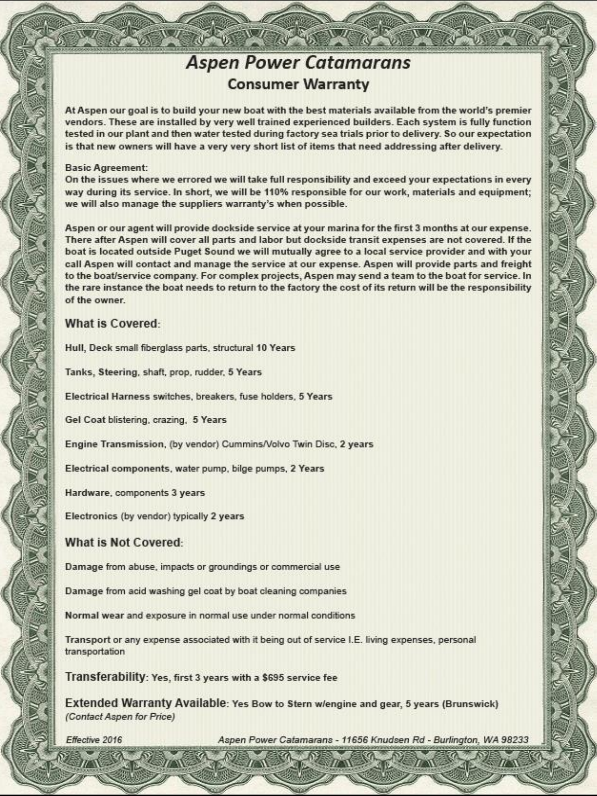
SECTION 2 Aspen Warranty 14
Boat US Membership 15
SECTION 3 Batteries & Chargers 16 – 21
AC / DC Panels 22 – 31
Shore Power 32 – 34
Generator 35 – 36
Tank Gauges 37
Pump Locations 38
Lenco Trim Tabs 39
SECTION 4 Getting Ready to Go 40 – 43
Anchor Operation 44 – 45
Engine & Transmission 46 – 49
Raw Water Ball Valves 50
Fresh Water System 51 – 52
LPG System 53 – 56
Toilet Water Operation 57
Dinghy Launch 58
Underwater Gear 59
Lifting Strap 60
Outfitting Your Boat 61 – 67
Open Hull 68 – 69
SECTION 5 Troubleshooting 70 – 81
Winterizing 82
SECTION 6 Larry’s Notes: Volvo Details 83 - 87
Larry’s Notes: Pettit Hydrocoat Details 88 - 89
Larry’s Notes: Thruster Logic & Strategy
90
Larry’s Notes: Toilet Logic, Details, Magic
91 – 95

VESSEL SPECIFICATIONS
VESSEL NAME: Keep Calm
REGISTRATION NUMBER:
HULL IDENTIFICATION NUMBER: US
–APE10158F818
MANUFACTURER:
Aspen
MODEL:
C120
LENGTH OVERALL:
43’-10”
LENGTH AT WATER LINE:
38’
BEAM:
14’
DRAFT:
39”
DISPLACEMENT:
22,500lbs
HULL MATERIAL:
Fiberglass
RUDDER TYPE:
Bronze
KEEL TYPE:
Fixed
BOTTOM PAINT: Pettit Hydrocoat Eco
GENERATOR 1:
Kohler
MODEL NUMBER:
EGEKOD
SERIAL NUMBER: SGM32K6TW
FUEL TYPE:
Diesel
ZINC SIZE:
0.25” x 0.78”
ALTERNATOR AMPERAGE:
50 @ 120V AC
ALTERNATOR BELT SIZE:
ED0024403380-S
PRIMARY FUEL FILTER:
Racor 30 Micron
SECONDARY FUEL FILTER:
ED0037302020-S
AIR FILTER:
OIL FILTER:
ED0021752850-S
ENGINE OIL TYPE:
SAE 15W-40
ENGINE OIL QUANTITY:
2.6 quarts
IMPELLER PUMP MAKE:
Kohler
IMPELLER PUMP MODEL:
229826
4

SERIAL NUMBERS
5
ENGINE
Volvo D6 435 A977251
GENERATOR
SGM32M9NK
DINGHY
ELECTRONICS
7612xsv Color Chart Plotter
401025278
7612 Display Screen (flybridge)
7616 Display Screen
46L004680
7612xsv Display Screen
3N1008474
GHC 20 (Flybridge)
5ET006154
GMR Fantom 24
4Z4002073
GHS 20 VHF Wireless Remote
VHF 210 with Hailer & Remote Mic
GHP 20 Autopilot with Smart Pump Kit
2Q4010932
GHC 20 Marine Autopilot Control Unit
5ET004303
Autopilot Reactor 40 CCU
5EE002801
AIS 600
1SS018912
Battery House 6V (quantity 4)
Batteries: Start, Generator, Electronics,
House (1 ea, 4 total)

CAPACITY SPECIFICATIONS
6
Unit Capacity Material
Waste Port
38 Gallons Polypropylene
Waste Starboard
45 Gallons Fiberglass
Water Port
52 Gallons Polypropylene
Water Starboard
53 Gallons Polypropylene
Fuel Port
92 Gallons Aluminum
Fuel Starboard
137 Gallons Aluminum
Engine Oil
5.28 Gallons
Transmission Fluid
1.84 Gallons
Generator Oil
2.4 Quarts
Hot Water
11 Gallons
Batteries House Bank
514 Amp Hours

SERVICE POINTS & PARTS
1
OIL CHANGE
Crank Case Breather Filter(D6-
435)
3584145
1 ea
Volvo Oil Filter (D6) 22030848
1 ea
Volvo Oil Filter By-Pass (D6) 22030852
1 ea
Delo 15W-40 Motor Oil GALLON
5.28 gallons
2
TRANSMISSION FLUID CHANGE
Transmission Filter
3312199031
1 ea
Trans Oil (D6 435) ATF Dexron iii 1.84 gallons
3
GENERATOR SERVICE KOHLER 6EKOD
Oil Filter
ED2175-285-S
1 ea
Oil
Secondary Fuel Filter
ED2175-288-S
1 ea
Zinc
90802150
1 ea
Belt Sea Water Pump
229125
1 ea
Impeller repair kit
229826
1 ea
4
ZINCS
Transom Zinc
MFG# CMDIVERMINI
2
Trim Tab Zinc (2-13/16”) MFG# CMR02
1
Sand Bar Zinc MFG# CMM24
1
Swim Step Zinc MFG# CMX07
4
Bow Thruster Zinc
MFG # SM71190A 2
Stern Thruster Zinc
MFG # SM71190A 1
7

ENGINE SPECIFICATIONS
ENGINE MANUFACTURER:
Volvo Penta
MODEL NUMBER:
D6-435
SERIAL NUMBER:
A977251
FUEL TYPE:
Diesel
ZINC SIZE:
N/A
ALTERNATOR AMPERAGE:
210 / 180
ALTNERATOR BELT SIZE:
Part #21407028
PROPELLOR SHAFT DIAMETER:
2”
PROPELLOR SHAFT ROTATION:
Right
PROPELLOR DIAMETER:
23”
PROPELLOR PITCH:
20”
NUMBER OF BLADES:
4
PROPELLOR MATERIAL:
Bronze
PRIMARY FUEL FILTER:
Racor 30 Micron
SECONDARY FUEL FILTER:
Part #21718912
AIR FILTER:
Part #21702999
OIL FILTER:
#22030848
BYPASS
#22030852
ENGINE OIL TYPE:
15W-40
ENGINE OIL QUANTITY:
5.3 gal
IMPELLER PUMP MAKE & MODEL:
Volvo
TRANSMISSION MANUFACTURER:
ZF
TRANSMISSION REDUCTION RATIO:
2:1
TRANSMISSION FLUID TYPE:
ATF
TRANSMISSION FLUID QUANTITY:
1.8 US Gallons
8

VOLVO D6 435 PARTS
9

ENGINE SPECTROGRAPHIC CHART
10

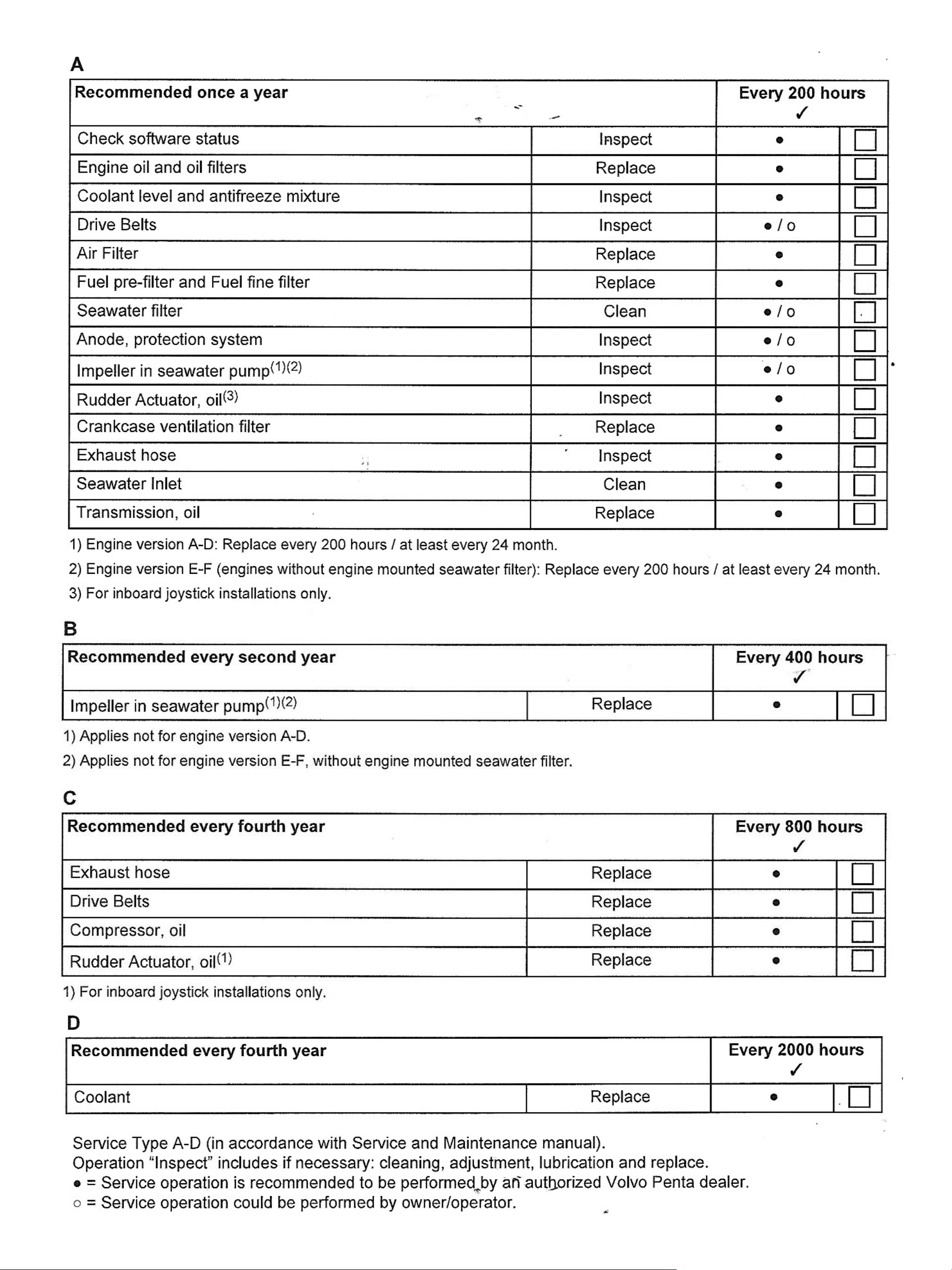
ENGINE MAINTENANCE SCHEDULE
Your Volvo Penta engine and its equipment are designed for high reliability
and long life. The engines are built to withstand the marine environment,
but also to have the smallest possible environmental impact. If the engine
and transmission are serviced regularly according to the schedule, these
qualities will be retained and unnecessary malfunctions will be avoided.
C = Clean
R = Replace
A = Adjust
L = Lubricate
I = Inspect
(clean, adjust, lubricate or replace if necessary)
FSI = First Service Inspection
A – F = Type of service
(regular service)
FSI: FIRST SERVICE INSPECTION, after 50
-100 running hours
Or within 180 days of the date of delivery, or the end of the first season, whichever comes first
Coolant level and antifreeze mixture
I
Drive belt and belt tensioner
I
Fuel pre
-filter, draining water / contamination
I C
Outboard drive, corrosion protection
I
Outboard drive, oil level in Power Trim
I
Outboard drive, oil level in Power steering
I
Start and warm up engine
Engine and transmission, oil / fuel / water leakage
I
Engine and transmission, abnormal noises
I
Power steering and Power Trim, function and leakage
I
Stop engine
Reverse gear, oil level
I
11

EVERY 100
-200 HOURS / AT LEAST EVERY 12 MONTHS
Oil change intervals vary, depending on engine type, oil grade, and sulfur content of the fuel
Engine oil and oil filters / by
-pass filter
R
Crankcase ventilation filter
R
Coolant level and antifreeze mixture
I
Air filter
R
Fuel pre
-filter and fuel fine filter
R
Seawater filter
I
Drive belt (tension)
I
Impeller, raw water pump
I
Reverse gear, oil and filter
R
Reverse gear, propeller shaft seal
I
Outboard drive, oil
R
Outboard drive, corrosion protection
R
Outboard drive, propeller shaft. Visual inspection of propeller seal
I L
Outboard drive, U
-joint and primary bearing
L
Outboard drive, bellows, rubber hoses, and clamps
I
Checking exhaust line
I
Outboard drive, universal joint bellow
I
Hydraulic hoses and fittings. Thoroughly inspect for signs of leaks, wear, cracks, aging
I
Engine and transmission, oil / fuel / water leakage
I
Engine and transmission, touch up paint as required
L
Batteries, electrolyte level
I
EVERY SECOND YEAR
Impeller, seawater pump
R
Outboard drive, universal joint bellow
R
EVERY FOUR YEARS
Coolant
R
EVERY 400 HOURS / AT LEAST EVERY 4 YEARS
Outboard drive, hydraulic valve oil and oil filter (steering control unit)
R
1213141516

BATTERY SWITCHES
The C120 has six main battery switches:
Normal operation position is to leave both House,
Electronics, and Engine switches in the ON position.
Emergency Parallel should be in the OFF position and is
rarely used and then only for 3 to 5 minutes max.
Thruster battery switches.
These must be switched OFF
when swimmers are in the water, or for service.
The
thrusters are very powerful and will suck objects in the
water toward them.
Do not operate the thruster for more than 30 seconds at
a time or the motor’s thermal breaker may shut the
motor off until it cools down.
Thruster Fuses: Bow is 400 AMP ANL Slow Blow. Stern
Is a 275 AMP ANL Slow Blow. (Note:
Stern thruster will
NOT operate if bow thruster fuse is blown
.)
1
HOUSE ON/OFF
Top of DC Panel Dash
2
ENGINE ON/OFF
Top of DC Panel Dash
3
ELECTRONICS ON/OFF
Top of DC Panel Dash
4
BOW THRUSTER
Under Master Bed-Stbd
5
STERN THRUSTER
Stbd Lazarette –
left lip
6
EMERGENCY PARALLEL
Starboard Lazarette
BOW THRUSTER
FUSE
BOW THRUSTER
SWITCH
STARBOARD LAZARETTE
EMERGENCY PARALLEL SWITCH
STERN THRUSTER FUSE
STERN THRUSTER SWITCH

BATTERY LOCATIONS
The C120 house battery bank is located in the starboard forward bow under the
bed steps and floor compartments. It’s comprised of 4 AGM 6 Volt golf cart style
batteries (in series for 12 volts) and one G-27 style batteries. The G-27 house
battery is near the engine and generator batteries under the starboard queen beds
aft cushion, this makes the run for the aft thruster shorter and more powerful.
17
HOUSE BATTERIES
ELECTRONICS
BATTERY
HOUSE
BATTERIES
HOUSE
BATTERY
ENGINE
BATTERY
GENERATOR
BATTERY
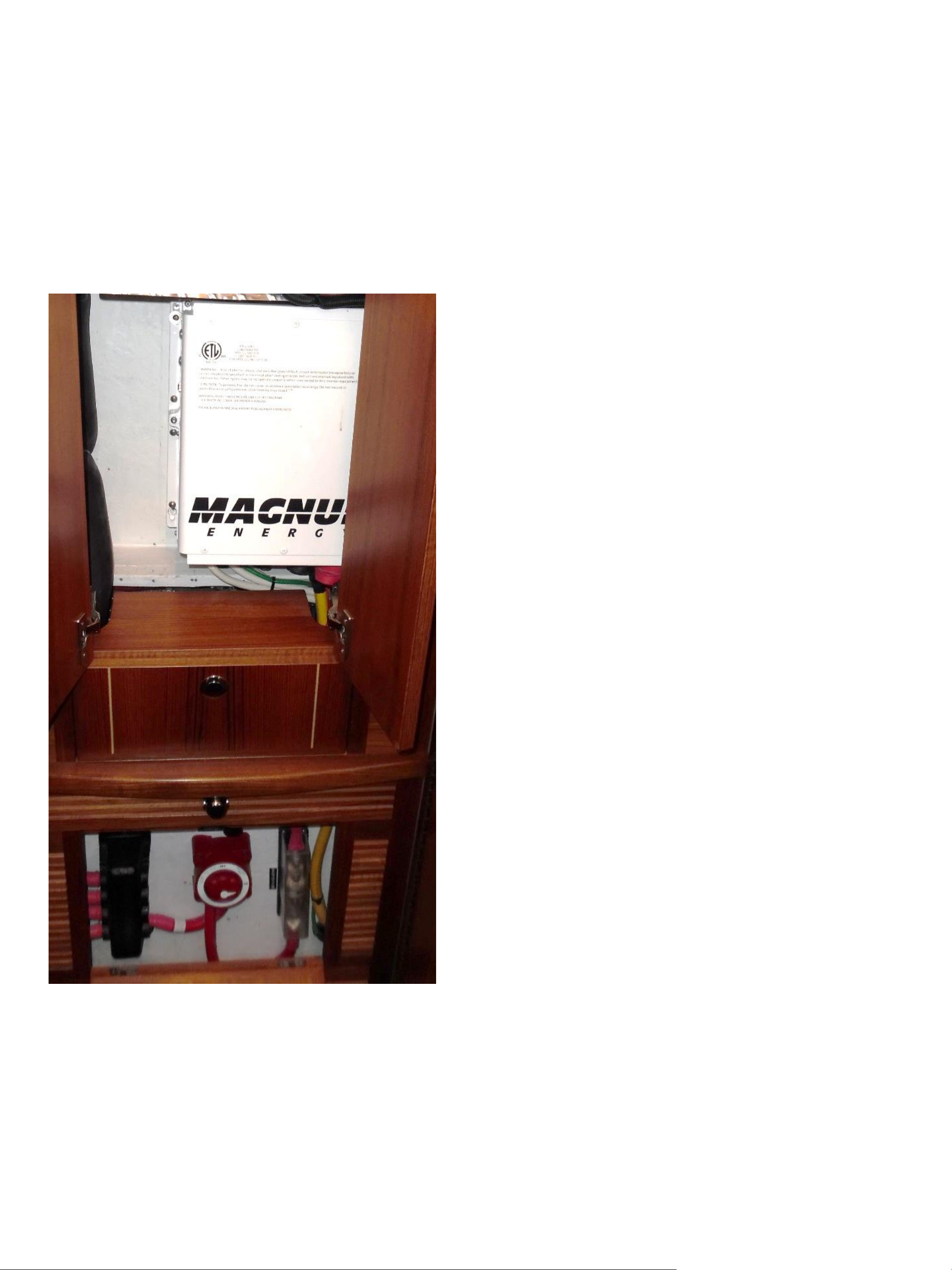
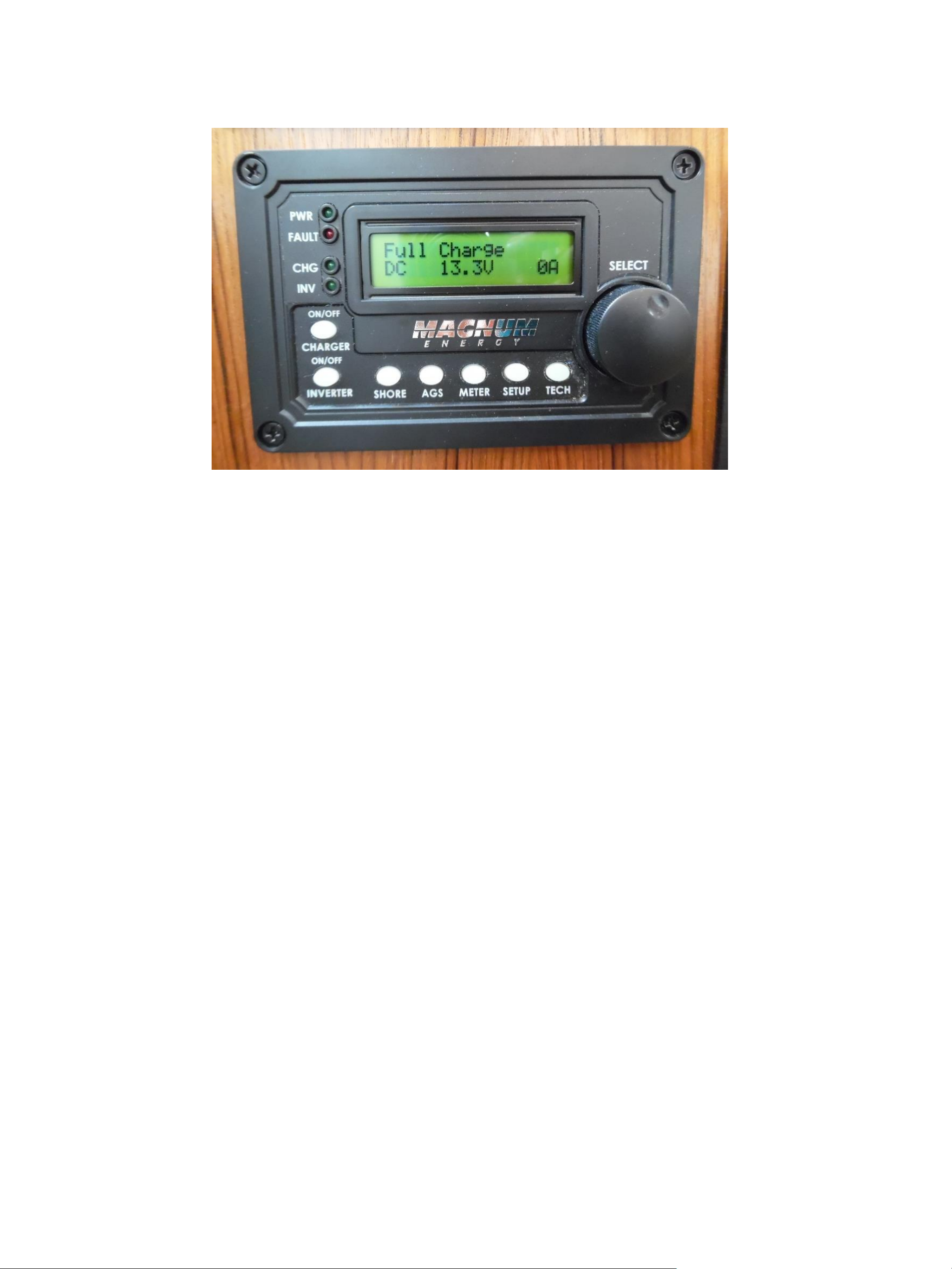
MAGNUM CHARGER INVERTER
The Magnum 1,000 or Opt 2,000 inverter
charger are combo units that supply 120V
AC power and also supply 12 volt 3 stage
charging either 60 or 100 amps. If the units
were in the on position when power was
disconnected they typically come back on
when they see 120V power again. To work
you need to see 120 volt power at the 120
V panel display and have the breakers on.
The Magnum inverter charger display will
light up and show its activity initially
typical “Bulk Charging 100 amps” this will
ramp down as the batteries fill up. The
charger is a three stage-smart unit that
charges aggressively when the battery is
low and then ramps down as it charges.
They stop completely when the battery is
fully charged and do a small topping charge
as needed. The design greatly extends
battery life and prevents overcharging and
subsequent battery damage. Note: the
chargers must be set to the AGM setting
to properly charge AGM batteries. Also
with AGM batteries there is no water level
to check they have a gel inside. This is
good but AGM batteries do not like being
run dead flat and will only do this 2-3
times before they must be replaced. We
chose AGM as they out gas hydrogen
(flammable) far less than lead acid
batteries and with their location in the
boat this is important to safety. If you
replace the batteries you must replace
with AGM
NOTE:
Chargers will only charge if they see
voltage. If batteries are dead you will need to
use the Emergency Parallel Switch and charge
for maximum 4-6 minutes for the charger to
see the battery and begin charging.
18
STARBOARD COMPANION WAY
This unit has two jobs, first is to charge the house batteries when in
port or when the generator is switched on and the slide switched
moved to Generator position. If the unit see’s inbound 120 Volt AC
power it passes it right through to those outlets connected to the
inverter. It can make 120 volt power as well by drawing 12Volt power
from the house batteries. But understand this works well for a micro
waving a cup of coffee or two or reheating dinner or charging phones
and computers. But if you’re going to use a LOT of inverted power,
say to run a hair dryer for 10 minutes, you will deplete the house
batteries very fast. The house bank is 420 amp hrs. so if you flatten
them it will take 4 hrs. with your 100 amp inverter charger to refill or
2 hrs. of running at cruise with the optional 210 amp dedicated house
alternator option to bring them back to full charge. For big AV 120
volt loads its best to start the generator let it warm up for 5 minutes
and then do any AC load you want. Note: Heavy loads on a cold
engine will damage the engine.
There are many settings and options on the inverter charger I
typically keep the charge capacity at 100 % with the size of our
house bank 100 Amps is just fine (no damage will occur) the only
time you may want to idle down the charger is when connected to a
limited capacity dock outlet if its popping you can reduce the draw by
lowering the charge amps. In normal use after docking and using the
thrusters the Magnum display will initially show bulk charging 60-90
amps, next it will show float charging 4-12amps (often stays in this
position when you using lights, chargers and other small loads). Just
note that if there are no green lights and nothing on the magnum
display showing you are not charging. The inverter is located under
the port side of the master bed though all its controls are just under
the DC panel at the dash.
19
MAGNUM CHARGER INVERTER
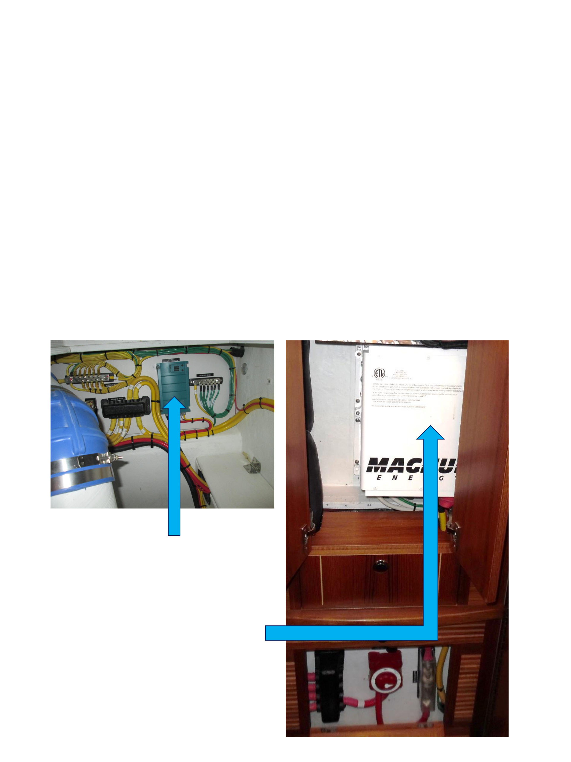
CHARGING SOURCES
20
The House batteries have two charging sources:
1)110 V Electric Battery Chargers:
❖House Inverter Charger (60 Amps for House battery bank) Note: On
boats with optional 2,000 watt inverter, the house bank has 100 Amp
charging. Shore power is connected and AC breakers above ¼ berth
are switched on. Inverter is switched on charging is switched on,
displays amps output on screen. Inverter charger can receive power
from Shore Power or Generator.
❖Engine Generator Charger: 25 AMP
2) Engine driven alternator: Engine battery is an excellent charge source
while cruising. (Optional 210 AMP house bank charger.)
ENGINE
GENERATOR
CHARGER
HOUSE
CHARGER
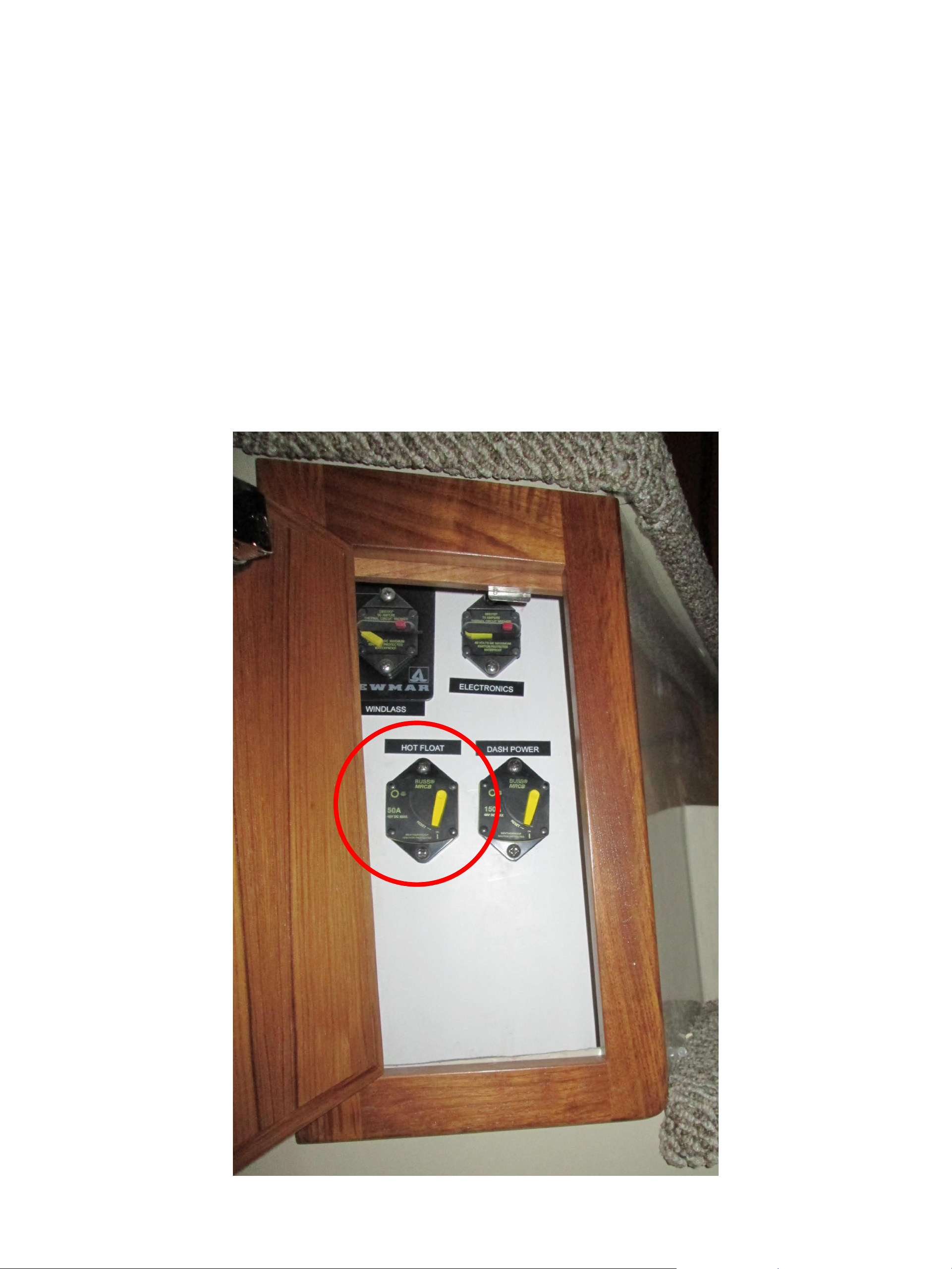
FULL-TIME POWER BREAKER
21
The Full-Time Power Breaker (Hot Float) is always on. The 12V power fuse is
mounted in a cabinet, inboard, starboard forward stateroom. It is important to
leave this on as it supplies power to the boat’s six automatic bilge pumps and
other devices that need power to save memory settings. It is not affected by
the battery switch position.
NOTE:
When the yellow lever is out/seen, the breaker is off. If the breaker has
popped or fuse is burned out, there is no bilge pump protection from leaks.

22
The main engine
batteries G27s are
located in the starboard
hull mid ships under the
aft end of the queen
berth as is the G27
Stern Thruster boost
battery. This
compartment is
accessed by the
removable bed cushion
and the hatch under. The
engine exhaust and
engine battery charger
are also in this
compartment. The aft
bulkhead here is
removable for easy
access to shaft coupler
and forward engine
mounts.
DC PANELS
DC SYSTEM OVERVIEW:
The C120 Has two main battery banks and two accessory batteries; one for the
generator and one for the electronics. In all there are 8 batteries in the system. These
are all AGM batteries and the chargers are set for AGM charge. The house bank is
comprised of 4ea 6 volt GC golf cart style batteries and one G27 to support the stern
thruster, the house bank supports the lights, pumps, heads, thrusters and Inverter. The
primary house bank is located under the floor boards forward in the master stateroom
Port hull. The dedicated electronics battery is also located in this area. The battery
switches and fuses for the house bank are located in the teak cupboard just above the
batteries as is the switch and Voltage Sensitive relay for the electronics battery. This
switch compartment also includes the Hot Float switch breaker that powers the 7 bilge
pumps even when the batteries are switched off (keeps the pumps active at all times)
Note: If you see the yellow tang hanging down this breaker is off = bad.
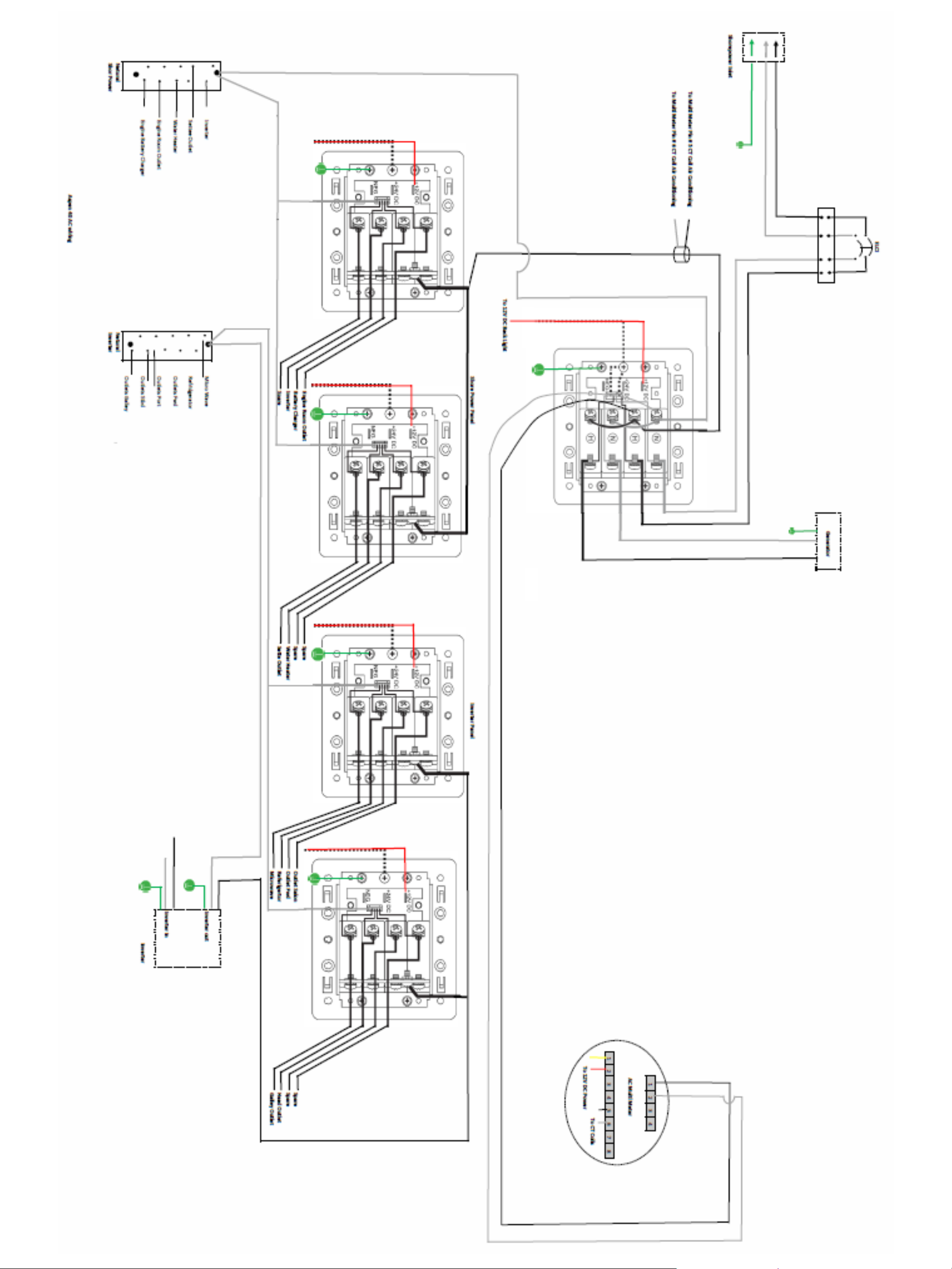
DC PANEL LAYOUT
23
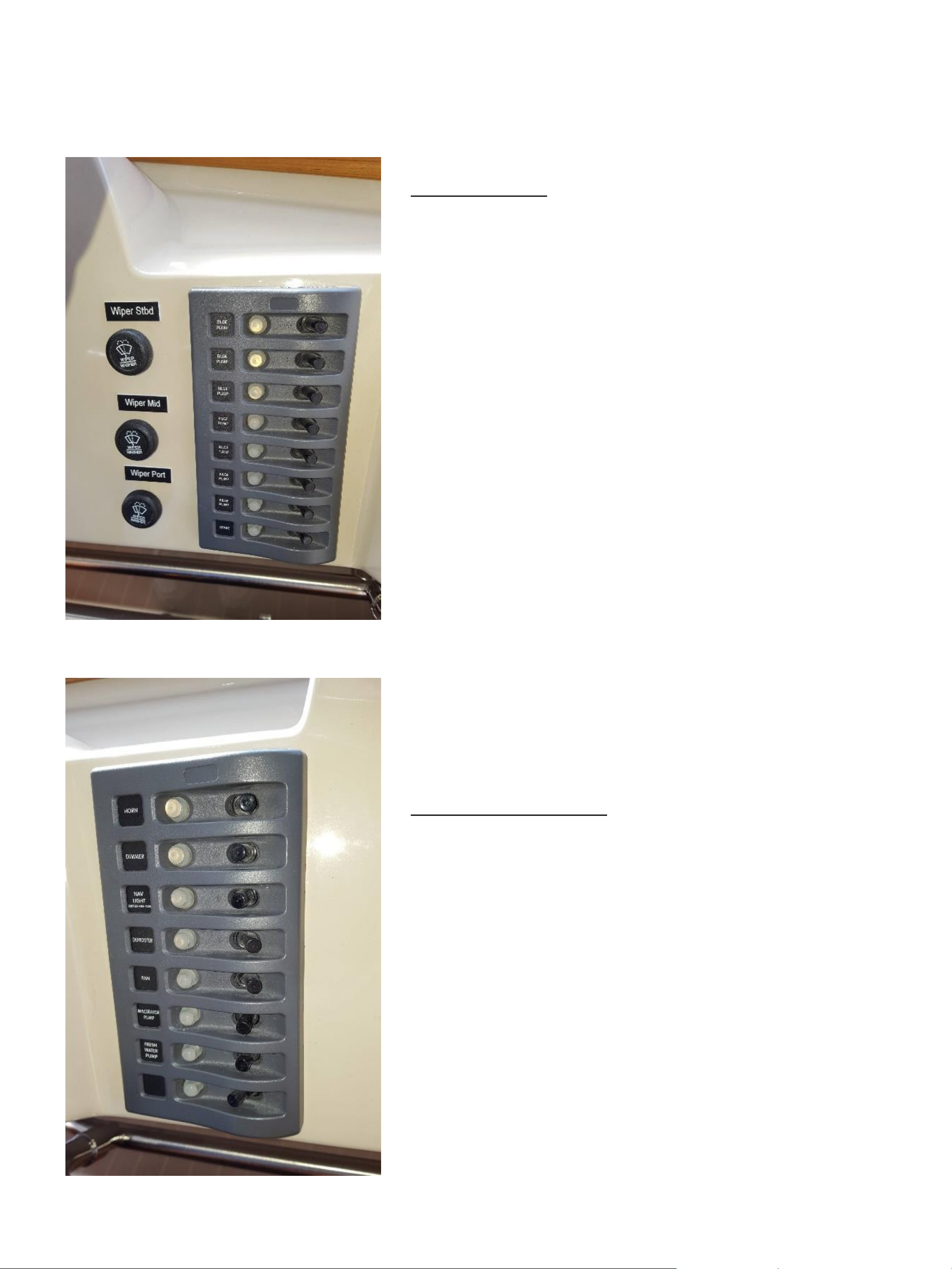
Pumps Panel: The pumps panel controls the bilge
pumps and shower sump pump. Most of these are
automatic, but these switches allow you to manually
turn on each of the six pumps for each water-tight
compartment. With the exception of the fresh water
switch, these switches are normally in the off
position. This panel is fed from the pumps breaker
on the main DC panel. The automatic portion of the
bilge pumps is not affected by this panel.
NOTE:
The engine room has a seventh pump
(1100GPH) which serves as an emergency pump. It
is wired to a very loud horn behind the dash. Should
you lose an engine hose and the engine room begins
to fill, this pump will automatically start and the
horn will sound. Stop and fix the problem.
Ship Systems Panel: This panel includes controls
for navigation lights, blower, and many other ship
systems. Like the Pumps Panel, it is fed from the
main DC panel breaker.
These panels have separate resettable circuit
breakers, ranging from 5- to -20 amps. If a breaker
has tripped, determine and fix the cause and reset
the breaker by pushing the clear button in. (Possible
causes could be debris in pump, shorted wire, etc.)
24
ELECTRICAL DRAWING
1 of 4
Starboard Bow Under Steps
Wire #12
Wire #7
Wire #14
Wire #8
Wire #6
Wire #13
House Wire #23
House Wire #24
See Page #2
House Pwr Fuse 500 Amp ANL
ElectronicsACR
House
Wire #19
Wire #20
Wire #16
House Batteries
Electronics Battery
House Batteries
Wire #26
Wire #2
Wire #5
Wire #11
Wire #1
Bow Thruster
Fuse
Wire #9
Thruster Switch
Wire #10
Bow Thruster
Hot Float
50 Amp
Electronics
80 Amp
Windlass
90 Amp
House
150 Amp
Wire #20
See Page #2
25
ELECTRICAL DRAWING
2 of 4
Hot Float Fuse Panel
Fuse Block #1
Fuse Block #2
Electronics Fuse Panel
To Hot Float
50 Amp Breaker
See Page #1
To Electronics
80 Amp Breaker
Main DC Panel
Dash
Wire #20
To House 150 Amp Breaker
Helm Negative Bus
Outboard Starboard
Companionway
See Page #3
See Page #1
House Wire #23
House Wire #24
House Mid Wire #30
House Mid Wire #29
Inverter / Charger
Wire #35
Inverter Switch
Wire #34
Wire #31
Wire #32
Inverter Fuse
300 Amp Class T
To Queen Stateroom
negative bus
Wire
26
ELECTRICAL DRAWING
3 of 4
Wire #50
Wire #45
Wire #46
See Page #4
See Page #4
Negative Bus (Shunt)
Wire #42
Stern Negative Bus
Bonding Bus
Engine / Generator
Generator Battery
Volvo ECM Wire
Magnum Temperature Sensor
Battery Charger Temperature
Balmar Temperature Sensor
Balmar Voltage Sensing Wire
1 Amp Fuse
Wire #38
House Battery
Wire #39
Wire #37
Wire #36
House Battery
Switch
House Mid Wire #30
House Mid Wire #29
Furnace Breaker
See Page #2
House Power Fuse
500 Amp ANL
Start Battery
Balmar / House Wire #41
Balmar / House Wire #40
See Page #4
Queen Stateroom Under Berth
27
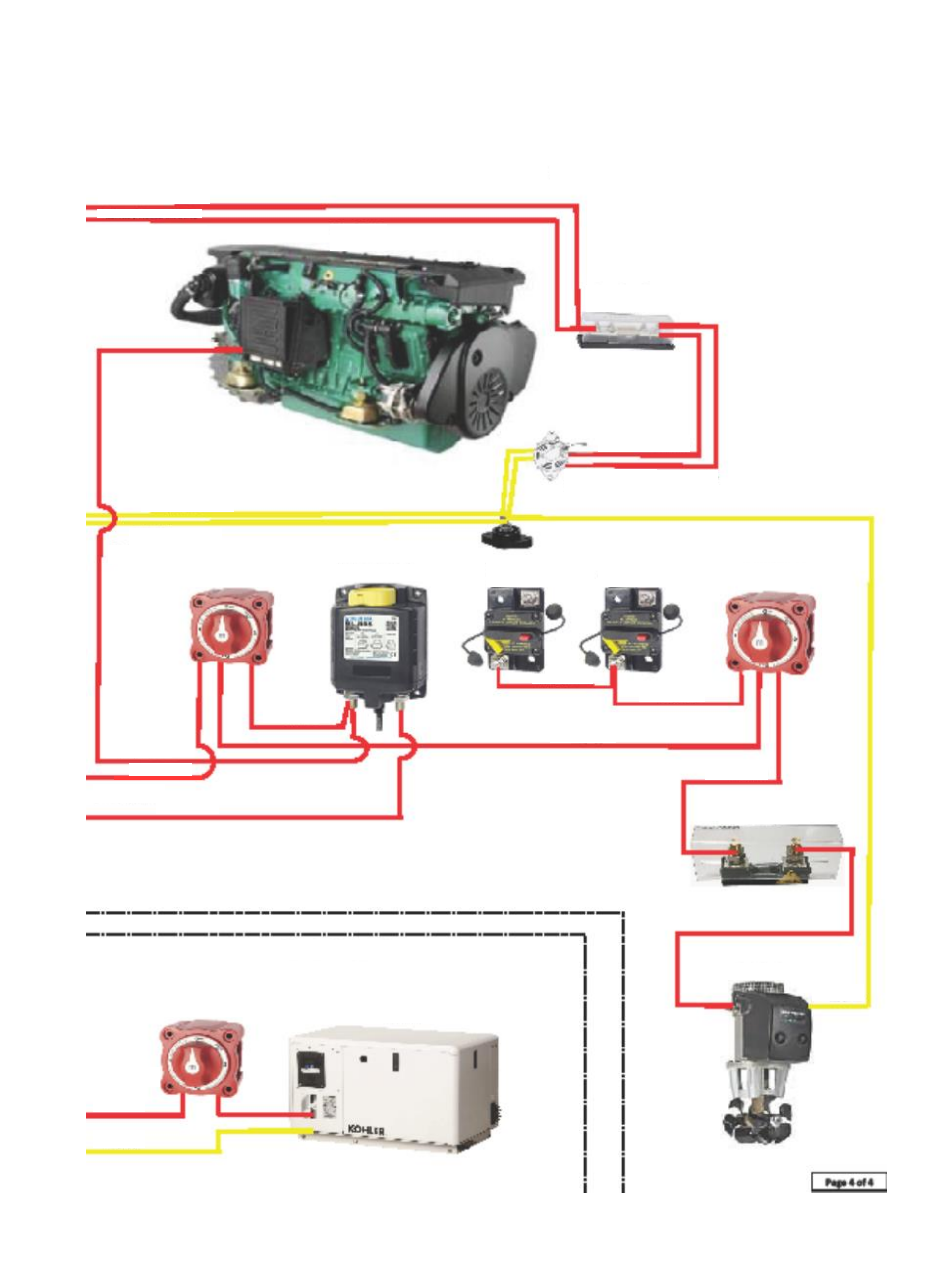
ELECTRICAL DRAWING
4 of 4
See Page 3
See Page 3
Volvo D6
435 Engine
Emergency Parallel
Engine Battery Switch
Stern Thruster
Shut Off
Generator Battery Switch
See Page 3
See Page 3
Generator Port Lazarette
Stern Thruster
Wire #45
Davit Breaker
60 Amp
Wire #46
Aft Deck Panel
30 Amp
Engine Room
Balmar
200 Amp Alternator
Wire #40
Wire #41
House Power Fuse
300 Amp ANL
Balmar / House Wire #40
Balmar / House Wire #41
Wire #62
Wire #54
Wire #57
Wire #53
Wire #56
Wire #58
Wire #51
Wire #59
Stern Thruster Fuse
250 Amp
Wire #44
Wire #49
Wire #50
Kohler 6EKOD
Generator
28
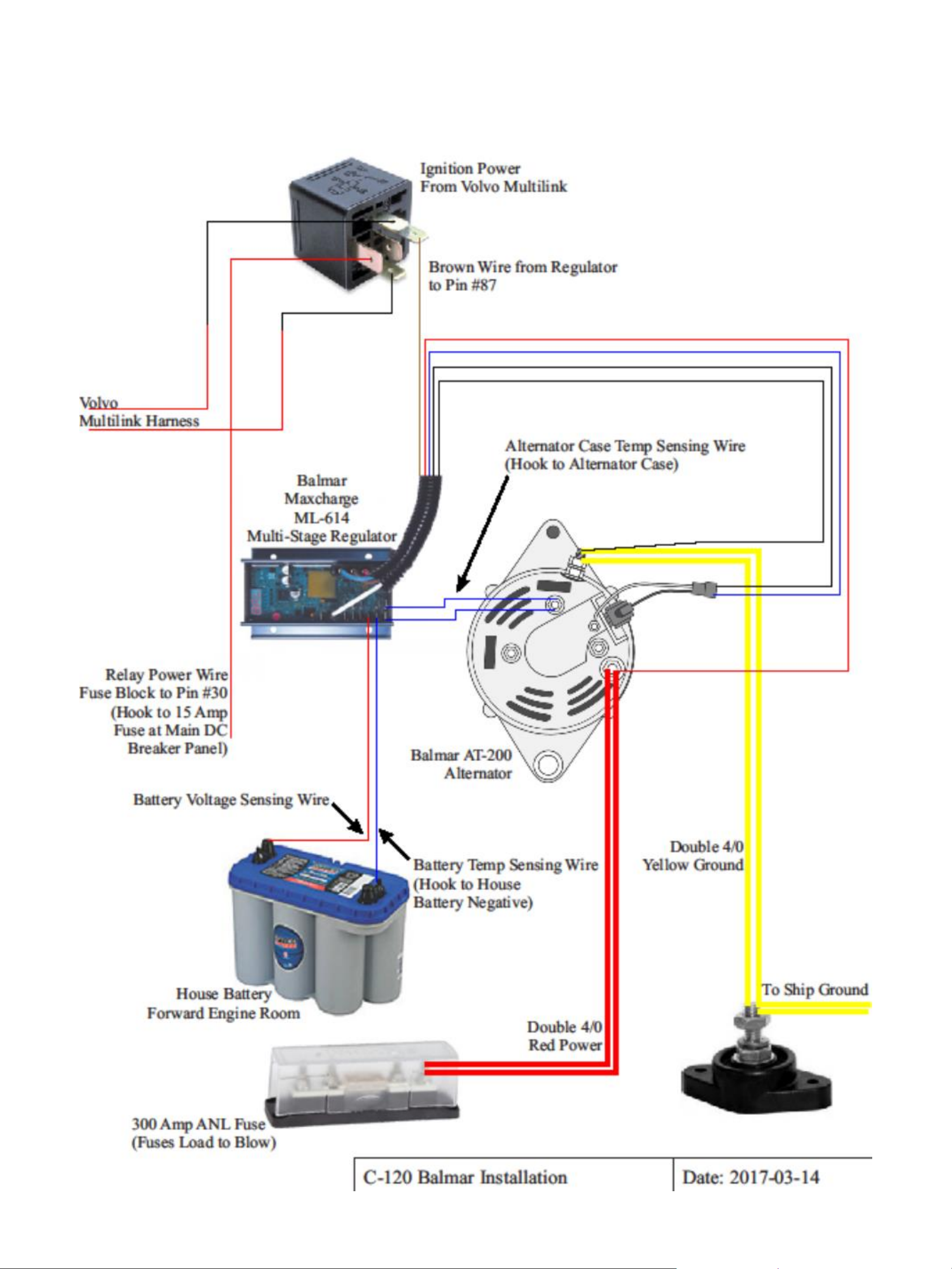
BALMAR CHARGER DIAGRAM
29
 Loading...