

Page 1
Aspect Medical Systems
A-2000™
BISPECTRAL INDEX™ (BIS™)
MONITORING SYSTEM
OPERATING MANUAL
Rx only
© Copyright, 2006, Aspect Medical Systems. All rights reserved. Copying or other
reproduction of this document is prohibited without prior written consent of Aspect
Medical Systems.
Aspect Medical Systems, Inc. Aspect Medical Systems International B.V.
One Upland Road Rijnzathe 7d2
Norwood, MA 02062 3454 PV De Meern
U.S.A. The Netherlands
(Tel) 617-559-7000 Tel: +31.30.662.9140
(Tel) 888-BIS INDE(X) (U.S. only) Fax: +31.30.662.9150 0123
(Fax) 617-559-7400 [email protected]
[email protected]
www.aspectmedical.com 070-0015 3.04
EC REP
Page 2

Considerations for Using BIS Monitoring
Clinical judgment should always be used when interpreting the BIS in conjunction with other
available clinical signs. Reliance on the BIS alone for intraoperative anesthetic management
is not recommended. As with any monitored parameter, artifacts and poor signal quality may
lead to inappropriate BIS values. Potential artifacts may be caused by poor skin contact (high
impedance), muscle activity or rigidity, head and body motion, sustained eye movements,
improper sensor placement and unusual or excessive electrical interference. Due to limited
clinical experience in the following applications, BIS values should be interpreted cautiously in
patients with known neurological disorders, those taking other psychoactive medications and in
children below the age of one.
Page 3

TABLE OF CONTENTS
ABOUT
INTRODUCING
INDICATIONS
INTRODUCTION...............................................................................................................
1 SAFETY PRECAUTIONS........................................................................................1-1
1.1 WARNINGS...........................................................................................................1-1
1.2 CAUTIONS............................................................................................................1-3
1.3 KEY
2 INSTALLATION AND PREPARATION FOR USE..................................................2-1
2.1 A-2000 BIS MONITOR INSTALLATION AND CHECKOUT .................................2-1
2.2 ENVIRONMENT....................................................................................................2-2
2.2.1 S
2.2.2 O
2.2.3 P
2.2.4 S
2.3 THE
2.3.1 T
2.3.2 D
2.3.3 P
2.3.4 BIS
2.3.5 A-2000
2.3.6 P
2.3.7 U
2.4 CABLE
2.5 START
2.6 MENU
2.6.1 L
2.6.2 T
2.6.3 S
THIS MANUAL.....................................................................................................I
THE A-2000 BIS MONITORING SYSTEM.............................................. II
FOR USE.................................................................................................. II
II
TO SYMBOLS...............................................................................................1-5
HIPPING AND STORAGE ENVIRONMENT................................................................2-2
PERATING ENVIRONMENT ...................................................................................2-2
OWER REQUIREMENTS AND SYSTEM GROUNDING ...............................................2-3
ITE PREPARATION: MOUNTING THE MONITOR ......................................................2-3
A-2000 BIS MONITORING SYSTEM - EQUIPMENT AND SUPPLIES.........2-5
HE BIS MONITOR................................................................................................2-6
IGITAL SIGNAL CONVERTER (DSC) ...................................................................2-10
ATIENT INTERFACE CABLE (PIC) .......................................................................2-10
SENSOR.......................................................................................................2-10
SYSTEM CONFIGURATIONS .....................................................................2-11
LATFORM COMPATIBILITY CONSIDERATIONS ......................................................2-12
PGRADING A-2000 STANDARD SYSTEMS...........................................................2-12
CONNECTIONS.....................................................................................2-13
PROCEDURE.........................................................................................2-13
SETTINGS ...............................................................................................2-13
ANGUAGE SELECTION MENU .............................................................................2-14
IME/DATE .........................................................................................................2-14
AVE SETTINGS.................................................................................................. 2-14
3 OPERATING THE A-2000.......................................................................................3-1
3.1 PREPARING
3.2 THE
3.3 THE
3.3.1 T
3.3.2 T
3.3.3 T
3.3.4 G
SENSOR CHECK AND SENSOR INTEGRITY CHECK................................3-3
BIS TREND SCREEN DISPLAY ...................................................................3-5
HE BIS (BISPECTRAL INDEX) NUMERIC REGION ...................................................3-5
HE SIGNAL QUALITY REGION ...............................................................................3-6
HE MESSAGE REGION .........................................................................................3-7
RAPHIC DISPLAY REGION ...................................................................................3-7
FOR OPERATION...........................................................................3-1
Page 4

3.4 THE
3.4.1 M
3.4.2 T
3.4.3 T
3.4.4 D
3.4.5 T
3.4.6 A
3.4.7 L
3.4.8 S
3.5 ALTERNATIVE
3.5.1 T
3.5.2 T
3.5.3 T
3.6 REVIEWING
3.7 ENDING
3.8 DATA
3.9 SOFTWARE
A-2000 SOFTWARE MENUS AND MENU SELECTIONS............................3-9
ENU NAVIGATION: ..............................................................................................3-9
HE SETUP MENU...............................................................................................3-10
HE ADVANCED SETUP MENU .............................................................................3-12
ISPLAY PARAMETER SETUP ..............................................................................3-16
HE DIAGNOSTIC MENU ......................................................................................3-18
LARM MENU .....................................................................................................3-18
ANGUAGE SELECTION MENU .............................................................................3-21
ENSOR DATA DISPLAY SCREEN AND SYSTEM CONFIGURATION MENU ................3-21
DISPLAYS.................................................................................3-22
HE DSA DISPLAY:.............................................................................................3-22
HE EEG DISPLAY..............................................................................................3-23
HE BIS LOG DISPLAY ........................................................................................3-24
STORED TREND DATA ................................................................3-27
A CASE ................................................................................................3-28
TRANSFER ..............................................................................................3-28
UPDATES......................................................................................3-29
4 QUICK REFERENCE GUIDE ..................................................................................4-1
5 FEATURES AND CAPABILITIES ...........................................................................5-1
5.1 HOW
THE A-2000 MONITORING SYSTEM WORKS...........................................5-1
5.2 SYSTEM
5.2.1 B
5.2.2 S
5.2.3 E
5.2.4 E
5.2.5 F
5.2.6 S
5.2.7 B
5.2.8 D
5.2.9 BIS
5.2.10 A
5.2.11 E
5.2.12 S
5.2.13 L
5.2.14 BIS
5.2.15 E
5.2.16 L
5.2.17 T
5.2.18 S
5.2.19 ICU
5.2.20 S
5.2.21 D
5.2.22 S
5.2.23 B
ISPECTRAL INDEX (BIS) ......................................................................................5-1
IGNAL QUALITY INDEX (SQI) ...............................................................................5-1
LECTROMYOGRAPH (EMG) INDICATOR ................................................................ 5-2
LECTROENCEPHALOGRAM (EEG) WAVEFORM DISPLAY .......................................5-2
ILTERS ............................................................................................................... 5-2
UPPRESSION RATIO (SR)....................................................................................5-2
URST COUNT (BURSTS/MIN) ............................................................................5-2
ENSITY SPECTRAL ARRAY (DSA) ........................................................................5-3
LOG DISPLAY .................................................................................................5-3
RTIFACT DETECTION .........................................................................................5-3
VENT MARKERS ................................................................................................5-3
TART AND END OF CASE BARS / CASE ID...........................................................5-3
IMIT ALARMS .....................................................................................................5-3
TREND SMOOTHING......................................................................................5-4
VENT PRINTING.................................................................................................5-4
ANGUAGES........................................................................................................5-4
IME/DATE AND CLEAR DATA MEMORY................................................................ 5-4
ENSOR DATA DISPLAY (BIS XP PLATFORM ONLY)..............................................5-4
MODE / EXTEND MODE.................................................................................5-4
YSTEM SELF-CHECKS .......................................................................................5-5
ATA MEMORY ...................................................................................................5-5
AVED SETTINGS................................................................................................5-6
ATTERY OPERATION..........................................................................................5-6
FEATURES............................................................................................5-1
Page 5

5.2.24 D
5.2.25 P
ATA TRANSFER AND SOFTWARE UPDATES.........................................................5-6
RINTED REPORTS .............................................................................................5-7
6 PREVENTIVE MAINTENANCE, CARE AND CLEANING ......................................6-1
6.1 CARE AND CLEANING ........................................................................................6-1
6.2 ROUTINE
6.3 FUSE
6.4 SYSTEM
6.5 TECHNICAL
6.6 INSTRUMENT
MAINTENANCE...................................................................................6-2
REPLACEMENT.........................................................................................6-3
CHECKOUT...........................................................................................6-4
DOCUMENTATION.........................................................................6-5
IDENTIFICATION..........................................................................6-5
7 DIAGNOSTICS AND TROUBLESHOOTING..........................................................7-1
7.1 THE
7.1.1 DSC
7.1.2 D
7.1.3 S
7.1.4 C
7.1.5 D
7.1.6 I
7.1.7 S
7.2 SYSTEM
7.3 WHAT
DIAGNOSTIC MENU.....................................................................................7-1
SELF-TEST................................................................................................... 7-2
ISPLAY SELF-TEST .............................................................................................7-2
ENSOR DATA DISPLAY (BIS XP PLATFORM ONLY)................................................7-2
LEAR DATA.........................................................................................................7-3
IAGNOSTIC CODES .............................................................................................7-3
MPEDANCE CHECKING .........................................................................................7-3
YSTEM CONFIGURATION MENU ........................................................................... 7-3
ERROR MESSAGE ALARMS...............................................................7-5
TO DO IF THE A-2000 REQUIRES SERVICE.........................................7-10
8 SPECIFICATIONS, WARRANTY AND SOFTWARE LICENSE AGREEMENT .....8-1
8.1 SPECIFICATIONS.................................................................................................8-1
8.2 WARRANTY..........................................................................................................8-4
8.3 SOFTWARE
LICENSE AGREEMENT..................................................................8-6
9 APPENDIX...............................................................................................................9-1
9.1 APPENDIX
9.2 A-2000
9.3 MENU
I – PROCESSED EEG VARIABLES ..................................................9-1
MENU MAP...............................................................................................9-2
LISTING.....................................................................................................9-5
Page 6

TABLE OF FIGURES
Figure 1 - Symbol Key....................................................................................................1-5
Figure 2 Pole Clamp .....................................................................................................2-4
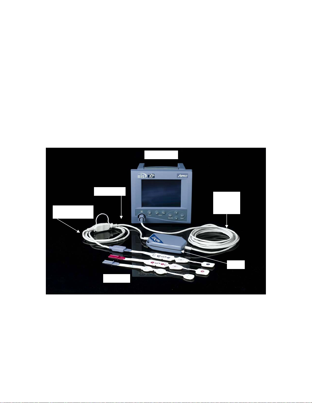
Figure 3 The A-2000 BIS Monitoring System................................................................2-5
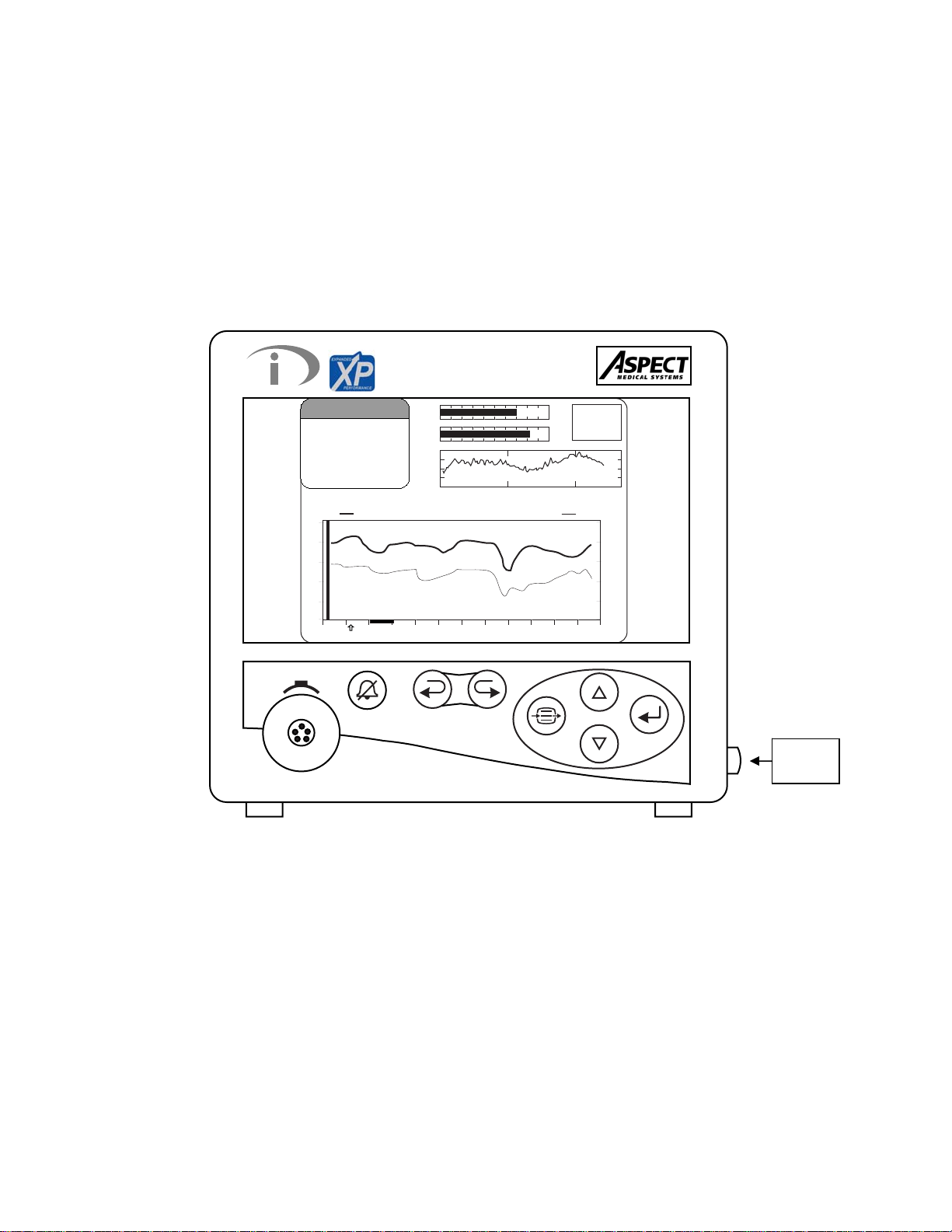
Figure 4 Front Panel (Example Illustration)...................................................................2-6
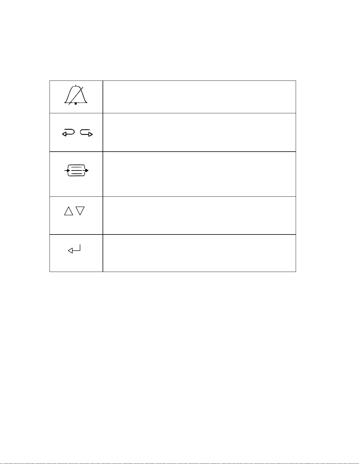
Figure 5 Front Panel Controls.......................................................................................2-7
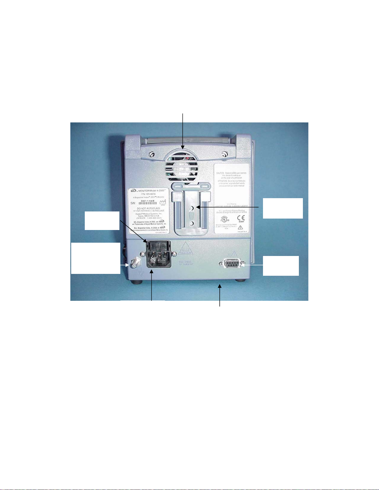
Figure 6 Rear Panel......................................................................................................2-8
Figure 7 BIS Sensor Connections...............................................................................2-12
Figure 8 Connecting the PIC (BIS XP Platform and XP Compatible) ...........................3-2
Figure 9 The Sensor Check (BIS Standard and BIS Pediatric sensors) ....................... 3-3
Figure 10 The Sensor Check (BIS Quatro and BIS Extend) .........................................3-4
Figure 11 - Screen Regions and Features.....................................................................3-5
Figure 12 The BIS Trend Display with BIS Extend Sensor in Use................................3-7
Figure 13 The BIS Trend Display..................................................................................3-8
Figure 14 Menu Navigation ........................................................................................... 3-9
Figure 15 Main Screen with Setup Menu and Trend Display......................................3-10
Figure 16 The Advanced Setup Menu ........................................................................3-12
Figure 17 The Display Parameter Setup screen ......................................................... 3-16
Figure 18 The Alarm Menu .........................................................................................3-18
Figure 19 The Language Selection Menu...................................................................3-21
Figure 20 The Density Spectral Array (DSA) Display .................................................3-22
Figure 21 The EEG Display ........................................................................................3-23
Figure 22 The BIS Log Display – Current Case..........................................................3-24
Figure 23 The BIS Log Display – Review Mode .........................................................3-25
Figure 24 Main Screen with Trend Review ................................................................. 3-27
Figure 25 The Diagnostic Menu .................................................................................... 7-1
Figure 26 Sensor Data Display .....................................................................................7-2
Figure 27 The System Configuration Menu ..................................................................7-3
Page 7

ABOUT THIS MANUAL
This Operating Manual contains all of the information you need to set up and operate the
Aspect Medical Systems’ A-2000 BIS Monitoring System (Figure 3). It also includes
specific cleaning and test procedures you may occasionally be required to perform.
Although this manual is intended for trained medical personnel, it does not assume prior
knowledge or experience with operator-programmable medical electronics devices.
Keep this Operating Manual with the A-2000 for use by the operator. This manual is
also intended to be a service information manual for service technicians or biomedical
engineering personnel.
Section 1 discusses important "Safety Precautions." Before attempting to set up or use
the A-2000, please familiarize yourself with the safety information provided in this
section.
Section 2 covers A-2000 installation, including system checkout, environmental
considerations, equipment and supplies needed, basic connections and setup.
Section 3 explains how to operate the A-2000 under normal conditions. It also covers
advanced features such as software updates and data transfer.
Section 4 serves as a quick reference for users who are already familiar with the
system.
Section 5 discusses the features and capabilities of the A-2000 system.
Section 6 covers normal care and cleaning procedures and maintenance, which should
be performed by the operator on a regular basis.
Section 7 covers diagnostics and troubleshooting and includes a summary of error
messages and actions that should be taken by the operator.
Section 8 details the system specifications, product warranty, and the software license
agreement.
Section 9 provides additional information on processed variables, and a menu map and
listing.
i
Page 8

INTRODUCING THE A-2000 BIS MONITORING SYSTEM
INDICATIONS FOR USE
The Aspect A-2000 EEG Monitor with BIS is intended for use under the direct
supervision of a licensed healthcare practitioner or by personnel trained in its proper
use. The BIS Monitor is intended for use on adult and pediatric patients within a hospital
or medical facility providing patient care to monitor the state of the brain by data
acquisition of EEG signals.
The BIS may be used as an aid in monitoring the effects of certain anesthetic agents.*
Use of BIS monitoring to help guide anesthetic administration may be associated with
the reduction of the incidence of awareness with recall in adults during general
anesthesia and sedation.
INTRODUCTION
The A-2000 BIS Monitoring System is a user-configurable patient monitoring system
designed to monitor the hypnotic state of the brain based on acquisition and processing
of EEG signals. The A-2000™ processes raw EEG signals to produce a single number,
called the Bispectral Index, or BIS, which correlates with the patient's level of hypnosis.
The A-2000 monitor display consists of:
• The current BIS number
• Trend plots of processed EEG parameters
• Raw EEG waveforms in real time
• Density Spectral Arrays (DSA)
• Numeric BIS log
• Various signal quality indicators (EMG, SQI).
• Suppression Ratio and Burst Count number.
The system performs self-tests to ensure that the monitor and its components are
functioning properly and that impedance levels of patient sensors are within acceptable
limits. Easy-to-use menus allow the user to mark events, review and clear stored data,
and change the data display.
* Gan TJ, Glass P, Windsor A, Payne F, Rosow C, Sebel P, Manberg P. Bispectral
Index Monitoring Allows Faster Emergence and Improved Recovery from
Propofol, Alfentanil and Nitrous Oxide Anesthesia. Anesthesiology October 1997;
(4) 87:808-15.
ii
Page 9

SECTION 1 SAFETY PRECAUTIONS
______________________________________________________________________
SECTION 1
1 SAFETY PRECAUTIONS
INTRODUCTION
Caution:
Carefully read this entire manual before using the
monitor in a clinical setting.
WARNINGS, CAUTIONS, AND NOTES
The terms warning, caution, and note have specific meanings in this manual.
• A WARNING advises against certain actions or situations that could result in
personal injury or death.
• A CAUTION advises against actions or situations that could damage equipment,
produce inaccurate data, or invalidate a procedure, although personal injury is
unlikely.
• A NOTE provides useful information regarding a function or procedure.
KEY TO SYMBOLS
A key to the symbols used on the A-2000 appears at the end of this section.
1.1 WARNINGS
GROUND WIRE LEAKAGE CURRENT MUST BE CHECKED WHENEVER
INSTRUMENT CASE IS OPENED BY A QUALIFIED BIOMEDICAL ENGINEERING
TECHNICIAN.
EXPLOSION HAZARD: DO NOT USE THE A-2000 IN A FLAMMABLE ATMOSPHERE
OR WHERE CONCENTRATIONS OF FLAMMABLE ANESTHETICS MAY OCCUR.
ELECTRICAL SHOCK HAZARD: DO NOT REMOVE MONITOR COVERS DURING
OPERATION OR WHILE POWER IS CONNECTED TO MONITOR.
ELECTRICAL SHOCK HAZARD: THE MANUFACTURER'S INSPECTION OF THIS
APPARATUS VERIFIED THAT THE GROUND LEAKAGE CURRENT AND THE
PATIENT SAFETY CURRENT WERE LESS THAN THE SPECIFIED LIMITS
ESTABLISHED BY THE APPLICABLE SAFETY STANDARDS. AS A MATTER OF
SAFE PRACTICE, THE INSTITUTION SHOULD CONDUCT PERIODIC TESTS TO
VERIFY THESE CURRENTS. WHENEVER AN EVENT SUCH AS SPILLAGE OF
BLOOD OR SOLUTIONS OCCURS, RE-TEST BEFORE FURTHER USE.
SHOCK HAZARD: DO NOT ATTEMPT TO DISCONNECT THE POWER CORD WITH
WET HANDS. MAKE CERTAIN THAT YOUR HANDS ARE CLEAN AND DRY
BEFORE TOUCHING THE POWER CORD.
1-1
Page 10

SECTION 1 SAFETY PRECAUTIONS
______________________________________________________________________
FOR PROPER GROUNDING, THE POWER RECEPTACLE MUST BE A THRE E-WIRE
GROUNDED OUTLET. A HOSPITAL GRADE OUTLET IS REQUIRED. NEVER
ADAPT THE THREE-PRONG PLUG FROM THE MONITOR TO FIT A TWO-SLOT
OUTLET. IF THE OUTLET HAS ONLY TWO SLOTS, MAKE SURE THAT IT IS
REPLACED WITH A THREE-SLOT GROUNDED OUTLET BEFORE ATTEMPTING
TO OPERATE THE MONITOR.
IF THE INTEGRITY OF THE EXTERNAL PROTECTIVE EARTH GROUND IS IN
DOUBT, THE A-2000 SHALL BE OPERATED FROM ITS INTERNAL BATTERY
POWER SOURCE ONLY.
FOR A-2000s USED OUTSIDE OF NORTH AMERICA: A HARMONIZED LINE CORD
WITH CONDUCTORS HAVING A CROSS SECTIONAL AREA GREATER THAN 0.75
2
mm
MUST BE USED.
THE CONDUCTIVE PARTS OF ELECTRODES OR SENSOR AND CONNECTORS,
INCLUDING THE NEUTRAL ELECTRODE, SHOULD NOT CONTACT OTHER
CONDUCTIVE PARTS, INCLUDING EARTH.
TO REDUCE THE HAZARD OF BURNS IN THE HIGH-FREQUENCY SURGICAL
NEUTRAL ELECTRODE CONNECTION, THE SENSOR OR ELECTRODES SHOULD
NOT BE LOCATED BETWEEN THE SURGICAL SITE AND THE ELECTROSURGICAL UNIT RETURN ELECTRODE.
THE SENSOR MUST NOT BE LOCATED BETWEEN DEFIBRILLATOR PADS WHEN
A DEFIBRILLATOR IS USED ON A PATIENT CONNECTED TO THE A-2000.
TO MINIMIZE THE RISK OF PATIENT STRANGULATION, THE PATIENT
INTERFACE CABLE (PIC) MUST BE CAREFULLY PLACED AND SECURED.
BE SURE THE MONITOR IS MOUNTED SECURELY IN PLACE TO AVOID
PERSONAL OR PATIENT INJURY.
UNIVERSAL PRECAUTIONS SHALL BE OBSERVED TO PREVENT CONTACT WITH
BLOOD OR OTHER POTENTIALLY INFECTIOUS MATERIALS. PLACE
CONTAMINATED MATERIALS IN REGULATED WASTE CONTAINER.
DO NOT MIX DISINFECTING SOLUTIONS (e.g., BLEACH AND AMMONIA), AS
HAZARDOUS GASES MAY RESULT.
WHEN CONNECTING EXTERNAL EQUIPMENT (e.g., DATA CAPTURE
COMPUTER), THE SYSTEM LEAKAGE CURRENT MUST BE CHECKED AND MUST
BE LESS THAN THE IEC601-1-1 LIMIT.
1-2
Page 11

SECTION 1 SAFETY PRECAUTIONS
______________________________________________________________________
THE USE OF ACCESSORY EQUIPMENT NOT COMPLYING WITH THE
EQUIVALENT SAFETY REQUIREMENTS OF THIS EQUIPMENT MAY LEAD TO A
REDUCED LEVEL OF SAFETY OF THE RESULTING SYSTEM. CONSIDERATION
RELATING TO THE CHOICE SHALL INCLUDE:
• USE OF THE ACCESSORY IN THE PATIENT VICINITY
• EVIDENCE THAT THE SAFETY CERTIFICATION OF THE ACCESSORY HAS
BEEN PERFORMED IN ACCORDANCE TO THE APPROPRIATE IEC 601-1
AND/OR IEC 601-1-1 HARMONIZED NATIONAL STANDARD.
REPLACE FUSES ONLY WITH ONE OF THE FOLLOWING PARTS:
Aspect P/N 430-0006, 1.25 Amps, 250V, 5x20mm
Littelfuse 217 Series, 1.25 Amps, 250V, 5x20mm
Wickmann 193 Series, 1.25 Amps, 250V, 5x20mm
ALWAYS REPLACE BOTH FUSES TOGETHER, EVEN IF ONLY ONE HAS FAILED.
1.2 CAUTIONS
Read this entire manual carefully before using the monitor in a clinical setting.
Do not autoclave the Digital Signal Converter or Monitor. Autoclaving will
seriously damage both components.
Do not block fan output. Keep at least three 3 inches of unobstructed space
between rear of instrument and wall and other instruments. Do not allow other
instruments to block airflow. Do not block ventilation inlet holes on the underside
of monitor.
Do not open Digital Signal Converter for any reason. The seal to prevent liquids
from entering the Digital Signal Converter may be damaged if opened. Service or
repairs must be performed only by qualified biomedical technicians.
Mixing of system configurations will increase sensor and hardware inventory
requirements and may create user and support issues.
Each BIS sensor type has its own placement method. Be sure to carefully follow
the appropriate package directions.
The A-2000 has been designed to operate with a disposable BIS Sensor. The
sensor is a silver/silver chloride electrode array that utilizes Aspect's patented
Zipprep technology and uses a proprietary connector. Use of other electrodes is
not recommended.
Continuous impedance checking may need to be disabled if the 1 nanoampere 128
Hz impedance check signal interferes with other equipment (e.g., evoked potential
monitors).
Check the battery periodically, by operating an A-2000 that has been disconnected
from the wall socket and that has been charging the battery for at least 4 hours.
After long periods of storage (e.g., more than 1 month) it may be necessary to
cycle (charge, then discharge) the battery a few times to get full charge capacity.
1-3
Page 12

SECTION 1 SAFETY PRECAUTIONS
______________________________________________________________________
If the A-2000 fails to operate reliably from the battery for 20 minutes, battery
replacement is required.
The A-2000 contains an internal Nickel-Metal-Hydride battery. The battery must be
removed by a qualified service technician and disposed of or recycled in
accordance with the national laws of the country. Contact Aspect Medical
Systems, Inc. or the local distributor for servicing of battery.
Avoid liquid ingress to the Patient Interface Cable. Contact of fluids with the PIC
sensor connector can interfere with PIC performance.
The A-2000 system complies with the electromagnetic compatibility requirements
of EN60601-1-2. Operation of this device may affect or be affected by other
equipment in the vicinity due to electromagnetic interference (EMI). If this occurs:
• Increase separation between devices
• Re-orient device cabling
• Plug devices into separate outlet circuit branches
Consult Aspect Medical Systems Technical Support for assistance.
When connecting or disconnecting Digital Signal Converter, take care not to touch
the exposed contacts of either connector. Damage due to electrostatic discharge
may result.
A-2000 is a trademark of Aspect Medical Systems, Inc.
Bispectral Index, BIS, the BIS logo, and Zipprep are trademarks of Aspect Medical
Systems, Inc. and are registered in the U.S.A., E.U. and other countries.
1-4
Page 13
SECTION 1 SAFETY PRECAUTIONS
______________________________________________________________________
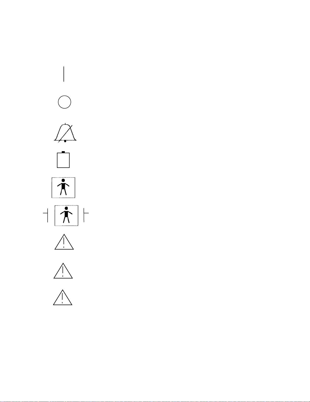
1.3 KEY TO SYMBOLS
ON (power; connection to the mains)
OFF (power; disconnection from the mains)
Audible Alarm Silenced
Operating on Battery
Type BF Equipment
J1
J2
Type BF Equipment Defibrillator-proof
Attention, Consult Accompanying Documents
Attention, J1 RS-232 Serial Port, Consult
Accompanying Documents
Attention, J2 Printer Port, Consult Accompanying
Documents
Figure 1 - Symbol Key
1-5
Page 14
SECTION 1 SAFETY PRECAUTIONS
______________________________________________________________________
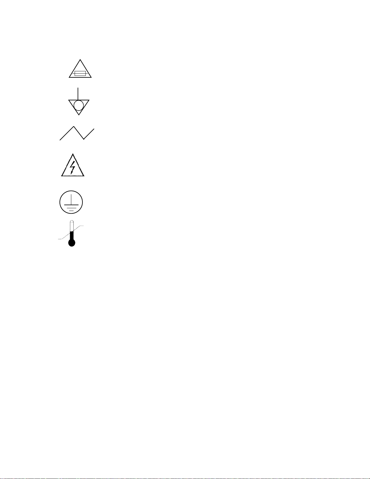
Fuse, Replace only with same Type and Rating
Equipotential
Alternating Current
Dangerous Voltage
Protective Earth (ground)
Storage Temperature Limits
Figure 1 Symbol Key (concluded).
1-6
Page 15

SECTION 2 INSTALLATION AND PREPARATION FOR USE
______________________________________________________________________
SECTION 2
2 INSTALLATION AND PREPARATION FOR USE
____________________________________________________
INTRODUCTION
This section provides installation instructions for the Aspect A-2000 BIS Monitor, Digital
Signal Converter, and accessories. It includes:
• Installation checklist
• Proper environment
• Required equipment and supplies
• Cable connections
• Start and shutdown procedures
• Menu settings
2.1 A-2000 BIS MONITOR INSTALLATION AND CHECKOUT
1. Open packages and inspect for all components:
• Monitor with power cable
• DSC
• PIC (Patient interface cable, connects DSC to patient)
2. Connect power cable to monitor, plug power plug into appropriate wall outlet.
3. Power up monitor by pressing power switch (lower, right side of case).
• Verify beep tone as power switch is activated.
• Verify fan (rear case wall) moves air outward.
• Verify all power on self-tests complete successfully (approx. 30 seconds).
• Verify next screen says ‘CONNECT DSC CABLE TO FRONT OF MONITOR.’
4. Connect DSC with PIC and Sensor.
• Verify DSC test completes.
• Verify SENSOR CHECK screen displays.
5. Exit from SENSOR CHECK screen by passing impedance check or by exiting with
MENU/EXIT key.
6. Disconnect power cord from rear of monitor.
• Verify ‘OPERATING ON BATTERY BACKUP (E33)’ is displayed.
• Verify battery icon displays in BIS banner.
7. Reconnect power cord.
• Verify battery icon is not displayed in BIS banner.
• Verify ‘OPERATING ON BATTERY BACKUP (E33) is not displayed.
8. Do keyboard checkout:
• Press SILENCE key Verify icon shows at BIS banner.
• Press ARROW BACK key Verify REVIEW MODE screen displays.
• Press MENU/EXIT key Verify REVIEW MODE screen exits.
2-1
Page 16

SECTION 2 INSTALLATION AND PREPARATION FOR USE
______________________________________________________________________
• Press ARROW AHEAD key Verify REVIEW MODE screen displays.
• Press MENU/EXIT key Verify REVIEW MODE screen exits.
• Press MENU/EXIT key Verify Setup menu displays.
• Press UP ARROW key Verify highlight bar moves up with each press.
• Press DOWN ARROW key Verify highlight bar moves down with each press.
• Press SELECT key Verify that highlighted menu line is selected.
• Press MENU/EXIT until BIS banner is displayed.
9. End of install.
2.2 ENVIRONMENT
2.2.1 Shipping and Storage Environment
The monitor and its accessories can be stored or shipped within the following
environmental limits. Note that these limits apply to non-operational storage and
shipping situations.
Temperature -20°C to +60°C
Humidity 15% to 95% (non-condensing)
Pressure 360 mmHg to 800 mmHg
Protect the monitor from sudden temperature changes that can lead to condensation
within the instrument. To minimize condensation, avoid moving the system between
heated buildings and outside storage. Once moved inside, allow the monitor to stabilize
in the unopened shipping container at the inside ambient temperature before unpacking
and placing into service. Before operation, wipe down all visible condensation and allow
the system to reach equilibrium at room temperature.
2.2.2 Operating Environment
The A-2000 is not designed for use in areas containing flammable gases or vapors.
WARNING!
EXPLOSION HAZARD: DO NOT USE THE A-2000 IN A FLAMMABLE
ATMOSPHERE OR WHERE CONCENTRATIONS OF FLAMMABLE
ANESTHETICS MAY OCCUR.
Temperature: The Aspect A-2000 Monitor is designed to operate safely at a room
temperature of 5°C to 40°C. Conditions that exceed these limits could affect reliability.
Humidity: The monitor is designed to operate within specifications at a relative non-
condensing humidity of 15% to 95%.
Pressure: The monitor will operate satisfactorily at or above sea level, and is unaffected
by extremes or changes in altitude within atmospheric pressures of 360 mmHg to 800
mmHg.
2-2
Page 17

SECTION 2 INSTALLATION AND PREPARATION FOR USE
______________________________________________________________________
2.2.3 Power Requirements and System Grounding
The A-2000 BIS Monitor requires a power source of 100-240 VAC, 50-60Hz. Current
consumption is 1 ampere maximum (including printer load).
To protect operating personnel and patients, the monitor must be properly grounded.
Accordingly, the monitor is equipped with a hospital grade line cord. The power cord
grounds the system to the power line ground when plugged into an appropriate
three-wire receptacle.
WARNING!
FOR PROPER GROUNDING, THE POWER RECEPTACLE MUST BE A
THREE-WIRE GROUNDED OUTLET. A HOSPITAL GRADE OUTLET
IS REQUIRED. NEVER ADAPT THE THREE-PRONG PLUG FROM
THE MONITOR TO FIT A TWO-SLOT OUTLET. IF THE OUTLET HAS
ONLY TWO SLOTS, MAKE SURE THAT IT IS REPLACED WITH A
THREE-SLOT GROUNDED OUTLET BEFORE ATTEMPTING TO
OPERATE THE MONITOR.
IF THE INTEGRITY OF THE EXTERNAL PROTECTIVE EARTH
GROUND IS IN DOUBT, THE A-2000 SHALL BE OPERATED FROM
ITS INTERNAL BATTERY POWER SOURCE ONLY.
FOR A-2000s USED OUTSIDE OF NORTH AMERICA - A
HARMONIZED LINE CORD WITH CONDUCTORS HAVIN G A CROSS
SECTIONAL AREA GREATER THAN 0.75 mm
2
MUST BE USED.
2.2.4 Site Preparation: Mounting the Monitor
Aspect Medical Systems, Inc. strongly recommends permanent mounting of the A-2000
monitor to the anesthesia machine to enhance safety and facilitate ease-of-use. Please
contact your local representative or Aspect to discuss mounting options.
WARNING!
BE SURE THE MONITOR IS MOUNTED SECURELY IN PLACE TO
AVOID PERSONAL OR PATIENT INJURY.
2.2.4.1 Direct Shelf Mounting
The A-2000 has a centrally located screw hole on its underside, in which a #10-24
machine screw can be used to secure the monitor to a shelf (via through-hole).
Engagement length of this screw hole is .23 inches (.58 cm). If a printer is attached, use
the holes on the underside of the printer.
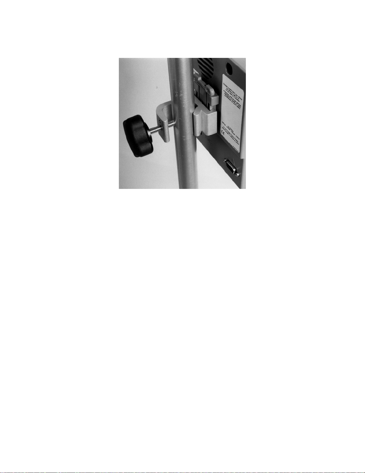
2.2.4.2 Mounting the Monitor using the Pole Clamp
To mount the monitor to a secure vertical pole (1/2" - 1½" in diameter):
1. Place pole within clamp bracket and tighten screw using the black finger knob.
Make sure that there is enough space above the clamp so that you have a few
inches to slide the monitor in from above.
2. Line up the clamp shoe (on back of monitor) with the slot on pole clamp and slide
monitor down to fit. The bottom of the clamp shoe should be seen well below the
bottom of the pole clamp, and the monitor should snap securely into place.
2-3
Page 18
SECTION 2 INSTALLATION AND PREPARATION FOR USE
______________________________________________________________________
Figure 2 Pole Clamp
To remove the monitor, press tab on top of clamp shoe before sliding monitor up.
The pole clamp may be locked onto the monitor so that the two do not get separated.
To do this:
1. Line up the clamp shoe (on back of monitor) with the slot on pole clamp and slide
monitor down to fit. The bottom of the clamp shoe should be seen well below the
bottom of the pole clamp and the monitor should snap securely into place.
2. Make sure that set screw hole on pole clamp aligns with corresponding hole on
clamp shoe.
3. Remove black knob screw from pole clamp.
4. Using the Allen wrench supplied, secure pole clamp to monitor with the set screw
provided.
5. Replace black knob screw.
6. To attach to pole, place pole within clamp bracket and tighten screw using the
black finger knob.
2.2.4.3 Optional Mounting Accessories
For information on optional mounting accessories, request Aspect’s “Monitor Mounting
Solutions” booklet (part number 070-0031)
2-4
Page 19
SECTION 2 INSTALLATION AND PREPARATION FOR USE
r
(
______________________________________________________________________
2.3 THE A-2000 BIS MONITORING SYSTEM - EQUIPMENT AND SUPPLIES
The A-2000 BIS Monitoring System consists of the following basic components:
• A-2000 BIS Monitor
• Digital Signal Converter (DSC)
• Patient Interface Cable (PIC)
• BIS Sensor
• Detachable Power Cord
A pole clamp is also included; however its use is optional. The exact model of DSC, PIC
and compatible sensors depends on the system configuration. Please consult section
2.2.4 for more detail. Contact Aspect or your local representative for information on
additional equipment and accessories.
BIS Monito
Patient Interface
Cable
DSC Pigtail
Monitor
Interface
Cable
PIC)
DSC
Sensors
Figure 3 The A-2000 BIS Monitoring System
2-5
Page 20
SECTION 2 INSTALLATION AND PREPARATION FOR USE
______________________________________________________________________
2.3.1 The BIS Monitor
2.3.1.1 Front Panel
The front panel of the BIS Monitor contains the Digital Signal Converter (DSC) port and
the controls needed for normal operation. See Figure 4.
B
s
BIS
5050
29 Mar 2001 12:59:23 CASE: Ab9r
BIS EMG
100
80
60
40
20
0
DSC
12:10 12:20 12:30 12:40 12:50 13:0012:00
Silence
SQI
EMG
EEG
-
25 mm/sec
Review
+
Menu/Exit
SR
25
0
μ
v/div
80
70
60
50
40
30
Select
Power
Button
Figure 4 Front Panel (Example Illustration)
2-6
Page 21
SECTION 2 INSTALLATION AND PREPARATION FOR USE
______________________________________________________________________
Front Panel Controls:
The [SILENCE] key toggles audible alarms on and off.
The left [←] and right [→] arrow keys are used to enter Review
mode and to scroll data backward and forward in time. In the BIS
Log, they show the previous [←] or next [→] screen of data.
The [MENU/EXIT] key is used to enter and exit the Setup Menu.
In Review mode it will return the user to the main screen. It is
also used to halt certain procedures, such as the sensor check,
and to answer "no" to a question.
The up [↑] and down [↓] arrows are used to move from one menu
selection to another. They are also used to increment and
decrement values. In the BIS Log, they are used to zoom time
out or in (increase or decrease reporting intervals).
The [SELECT] key is used to move between options within a
menu selection, to confirm an entry, and to answer "yes" to a
question.
Figure 5 Front Panel Controls
2.3.1.2 Power Button (Side Panel)
The power button is located on the lower right side of the monitor. It powers both the
monitor and the digital signal converter when the DSC is connected to the monitor. If a
power loss occurs, an internal back-up battery will supply power to the system. The
back-up battery charges when the monitor is plugged into the AC supply and the
power is ON.
2.3.1.3 Rear Panel
The rear panel components are pictured in Figure 6. They include: the fan, clamp shoe,
potential equalization terminal, power cord receptacle with fuse holder, and the RS-232
serial port. A printer connection port is located on the bottom underside of the monitor.
Only an Aspect-supplied printer will function with this port.
2-7
Page 22
SECTION 2 INSTALLATION AND PREPARATION FOR USE
______________________________________________________________________
Fuse
Fan
Clamp
Shoe
Potential
Equalization
Terminal
REPLACE FUSES ONLY WITH ONE OF THE FOLLOWING PARTS:
Aspect P/N 430-0006, 1.25 Amps, 250V, 5x20mm
Littelfuse 217 Series, 1.25 Amps, 250V, 5x20mm
Wickmann 193 Series, 1.25 Amps, 250V, 5x20mm
ALWAYS REPLACE BOTH FUSES TOGETHER, EVEN IF ONLY ONE
HAS FAILED.
AC Power
Supply
Printer
Port
Figure 6 Rear Panel
WARNING!
Serial
Port
2-8
Page 23

SECTION 2 INSTALLATION AND PREPARATION FOR USE
______________________________________________________________________
The fan prevents temperature inside the monitor chassis from rising above optimum
operating levels.
Caution:
Do not block fan output. Keep at least 3 full inches of unobstructed
space between rear of instrument and wall and other instruments.
Do not allow other instruments to block airflow. Do not block
ventilation inlet holes on the underside of monitor.
The clamp shoe allows the monitor to slide into the pole clamp so that it can be
attached to a ½” – 1 ½” diameter vertical pole.
The potential equalization terminal may be used to ground the monitor and its
components.
The power cord receptacle is used to plug in a three-prong hospital grade power cord
to provide power to the monitor and to the DSC when attached.
The printer port is provided to attach the monitor to the Aspect A-2000 Printer.
Caution:
The A-2000 system complies with the electromagnetic compatibility
requirements of EN60601-1-2. Operation of this device may affect or be
affected by other equipment in the vicinity due to electromagnetic
interference (EMI). If this occurs:
• Increase separation between devices
• Re-orient device cabling
• Plug devices into separate outlet circuit branches
Consult Aspect Medical Systems Technical Support for assistance.
The RS-232 serial port is used to transfer data to and from the monitor. It is also used
in testing and in software updates.
WARNING!
WHEN CONNECTING EXTERNAL EQUIPMENT (e.g., DATA CAPTURE
COMPUTER), THE SYSTEM LEAKAGE CURRENT MUST BE
CHECKED AND MUST BE LESS THAN THE IEC601-1-1 LIMIT.
THE USE OF ACCESSORY EQUIPMENT NOT COMPLYING WITH THE
EQUIVALENT SAFETY REQUIREMENTS OF THIS EQUIPMENT MAY
LEAD TO A REDUCED LEVEL OF SAFETY OF THE RESULTING
SYSTEM. CONSIDERATION RELATING TO THE CHOICE SHALL
INCLUDE:
• USE OF THE ACCESSORY IN THE PATIENT VICINITY
• EVIDENCE THAT THE SAFETY CERTIFICATION OF THE
ACCESSORY HAS BEEN PERFORMED IN ACCORDANCE TO
THE APPROPRIATE IEC 601-1 AND/OR IEC 601-1-1
HARMONIZED NATIONAL STANDARD.
2-9
Page 24

SECTION 2 INSTALLATION AND PREPARATION FOR USE
______________________________________________________________________
2.3.1.4 Integral Battery
A rechargeable nickel-hydride battery inside the monitor provides approximately 20
minutes of back-up power when power cannot be supplied via the power cord.
Recharge time is approximately 4 hours.
When the battery reaches a low power condition, the monitor will beep and blink the
battery symbol displayed on the screen. In addition, a battery low message will blink
continuously on the screen.
Caution:
Check the battery periodically, by operating an A-2000 that has been
disconnected from the wall socket and that has been charging the
battery for at least 4 hours. After long periods of storage (e.g., more
than 1 month) it may be necessary to cycle (charge, then discharge)
the battery a few times to get full charge capacity. If the A-2000 fails
to operate reliably from the battery for 20 minutes, battery
replacement is required.
The A-2000 contains an internal Nickel-Metal-Hydride battery. The
battery must be removed by a qualified service technician and
disposed of or recycled in accordance with the national laws of the
country. Contact Aspect Medical Systems, Inc. or the local
distributor for servicing of battery.
2.3.2 Digital Signal Converter (DSC)
The Digital Signal Converter is used to receive patient EEG signals. It is located close to
the patient's head where the EEG signal is less subject to interference from other
medical equipment. The DSC amplifies and digitizes the signals so that they are
received clearly by the monitor.
The Digital Signal Converter is shown in Figure 3. The long flexible Monitor Interface
Cable connects to the front of the monitor, and the shorter "DSC pigtail" cable connects
to the Patient Interface Cable (PIC).
The attachment clip on the DSC is used to secure it in a convenient location near the
patient's head.
Caution:
Do not open Digital Signal Converter for any reason. The seal to
prevent liquids from entering the Digital Signal Converter may be
damaged if opened. Service or repairs must be performed only by
qualified biomedical technicians.
2.3.3 Patient Interface Cable (PIC)
Aspect's BIS Sensor Patient Interface Cable (see Figure 3) connects the DSC to the BIS
Sensor.
2.3.4 BIS Sensor
After the BIS Sensor has been placed correctly on the patient's head, it is connected to
the PIC.
2-10
Page 25

SECTION 2 INSTALLATION AND PREPARATION FOR USE
______________________________________________________________________
2.3.5 A-2000 System Configurations
The chart below details the three A-2000 BIS monitoring system configurations: the BIS
XP Platform, the XP Compatible System, and the Standard System.
Component
A-2000
BIS XP Platform
A-2000
XP Compatible
A-2000
Standard System
Monitor
DSC
PIC
A-2000 Monitor
DSC-XP*
PIC Plus
Compatible
Sensors**
BIS Quatro
BIS Extend
BIS Pediatric
* Some early versions of the A-2000 BIS XP Platform may be supplied with a DSC-3
** BIS Sensor Plus (where sold) is also compatible with the BIS XP Platform and XP Compatible Systems
A-2000 Monitor A-2000 Monitor
DSC-2 DSC-2
PIC Plus Adapter PIC-S
BIS Quatro
BIS Extend
BIS Standard
BIS Pediatric
2.3.5.1 The BIS XP Platform
The BIS XP Platform represents Aspect’s top-of-the-line BIS monitoring solution.
Operational differences between it and the Standard System include:
• Compatible with new line of sensors including BIS Quatro, BIS Extend, and BIS
Pediatric
• DSC-XP with new processing capabilities
• Improved sensor connector with increased comfort in prone patients
• Enhanced sensor troubleshooting via Sensor Data Display (see Section 7.1.3)
2.3.5.2 XP Compatible
The Adapted System offers some of the features of the XP Platform, but at a lower
upgrade cost. Operational differences between it and the Standard System include:
• Compatible with BIS Quatro, BIS Extend and BIS Pediatric sensors
• Improved sensor connector with increased comfort in prone patients
2-11
Page 26
SECTION 2 INSTALLATION AND PREPARATION FOR USE
______________________________________________________________________
2.3.6 Platform Compatibility Considerations
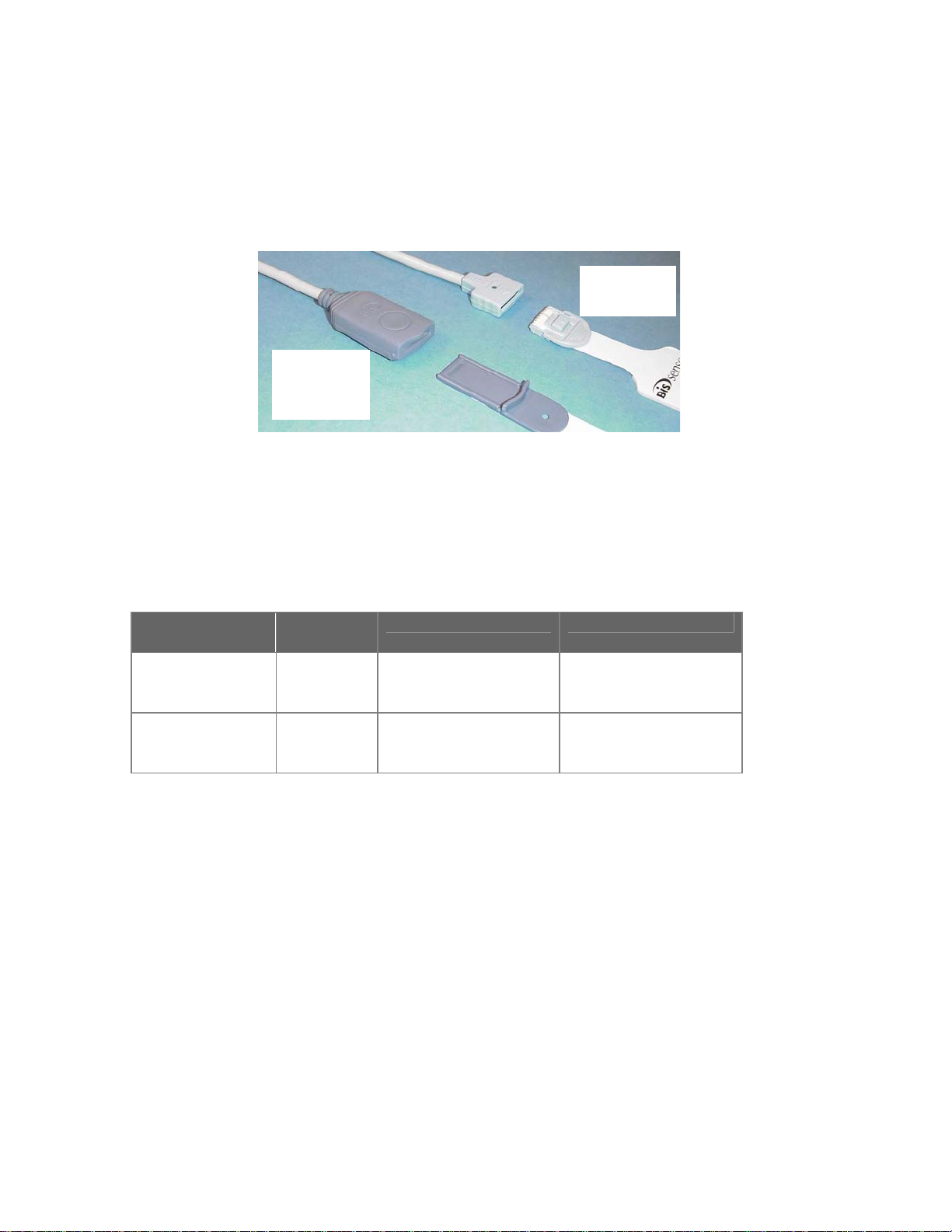
Aspect’s new sensors (BIS Quatro, BIS Extend and BIS Pediatric) are only compatible
with new BIS systems (BIS XP Platform and XP Compatible) by virtue of an improved
sensor connector (see figure below) and other features.
Quatro/
Extend/
Pediatric
Standard
Figure 7 BIS Sensor Connections
Caution:
Mixing of system configurations will increase sensor and hardware
inventory requirements and may create user and support issues.
2.3.7 Upgrading A-2000 Standard Systems
Aspect offers two upgrade options for A-2000 systems:
Upgrade
Option
XP Upgrade Kit
PIC Plus
Adapter
Also available is the Pediatric Upgrade Kit (P/N 186-0136), which includes a PIC Plus
Adapter and 25 BIS Pediatric sensors.
Aspect or your local distributor will help coordinate upgrades including the following:
• Software upgrade (if necessary) to System Software 3.10 or above
• Replacement and return of appropriate cabling (e.g., DSC-2s, PIC-Ss)
• Replacement and return of obsolete BIS sensors (if covered)
• Follow-up in-servicing (e.g., new BIS Quatro or BIS Extend placement)
Contact Aspect or your local distributor at your earliest convenience to schedule your
upgrade.
Customers are encouraged to manage sensor inventory to minimize
levels on upgrade day, as Aspect (or distributor) may not cover complete
replacement.
Part
Components Resulting System
Number
186-0125
(English)
DSC-XP
PIC Plus
Operating Manual
186-0126 PIC Plus Adapter
(Operating Manual
available separately)
Note:
A-2000
BIS XP Platform
A-2000
XP Compatible
2-12
Page 27

SECTION 2 INSTALLATION AND PREPARATION FOR USE
______________________________________________________________________
2.4 CABLE CONNECTIONS
After you have familiarized yourself with the safety information in the introductory section
of this manual and have prepared a suitable environment, follow these steps to prepare
the A-2000 system for operation.
1. Connect the DSC to the monitor
Holding the connector with the flat side up, plug the DSC cable into the DSC
port on the front of the monitor.
Once connected, the DSC need not be disconnected again. However, if you
wish to disconnect the DSC cable from the monitor, carefully pull on the blue
rubber overlay. DO NOT pull on the gray cable.
2. Connect the PIC to the DSC
Attach the Patient Interface Cable to the "DSC pigtail" extending from the DSC
unit.
Note:
Before connecting, carefully line up the markings on the connectors for
proper pin alignment. To disconnect the PIC, grasp the connector housing
and pull firmly. DO NOT pull apart by the cable wire.
2.5 START PROCEDURE
To start the instrument:
1. Attach one end of the power cord to the rear panel of the monitor.
2. Plug the other end of the power cord into a properly grounded hospital-grade AC
power outlet.
3. Press side panel POWER button. The internal back-up battery charges only
when the monitor is powered on and plugged into the AC outlet.
Powering on the monitor will initiate a self test procedure to be certain that the
equipment and connections are operating properly. If there is a problem, the system will
halt and an error message will appear. Error messages are explained in the
Troubleshooting section of this manual.
To shut the system down, simply press the POWER button.
2.6 MENU SETTINGS
Before using the A-2000 for the first time, you may need to select the proper language
and set the current date and time. Other setting options are discussed in detail in
Section 3.
To move from one selection to another, use the up [↑] and down [↓] arrows to
highlight the option you desire. Then follow the instructions below:
2-13
Page 28

SECTION 2 INSTALLATION AND PREPARATION FOR USE
______________________________________________________________________
2.6.1 Language Selection Menu
The A-2000 is designed to support multiple languages. If the screen does not display
the desired language, follow these steps to display the Language Selection Menu:
1. Press [MENU/EXIT] to access the Setup Menu.
2. Highlight Advanced Setup using the up [↑] or down [↓] arrows.
3. Press [SELECT].
4. Highlight Language Selection Menu using the up [↑] or down [↓] arrows.
5. Press [SELECT]. The Language Selection Menu displays.
To change languages:
1. Press [SELECT] until the desired language is selected.
2. Use the up [↑] or down [↓] arrows to highlight Return to Advanced Setup Menu
and press [SELECT]. This will redisplay the Advanced Setup Menu in the
selected language.
3. To make sure that the selected language displays every time the monitor is
turned on, use the arrows to highlight Save Settings, then press [SELECT] to
save setting changes.
2.6.2 Time/Date
To set the current time and date:
1. Press [MENU/EXIT] to access the Setup Menu.
2. Highlight Advanced Setup using the up [↑] or down [↓] arrows.
3. Press [SELECT].
4. Highlight Time/Date using the up [↑] or down [↓] arrows.
5. Press [SELECT] until the date or time value you wish to update appears in
reverse video.
6. Use the up [↑] or down [↓] arrows to increase or decrease the values displayed.
7. Press [SELECT] to move to the next date or time value.
8. To save the date or time changes, press [SELECT] at the last Time/Date option
(minutes). Pressing [Menu/Exit] before this last option aborts previous changes.
9. Press [MENU/EXIT] to exit from the Advanced Setup Menu.
Note:
The time/date is initially set for the Eastern Standard Time zone (USA). It
will be necessary for you to change the time twice per year using the
Time/Date feature if you are located in a time zone that alters its clocks at
the beginning or end of Daylight Savings Time.
When a time/date is entered that is earlier than the current time/date in
the monitor, all data memory will be erased. The prompt, "Clear Data
Memory?" will appear to alert you of this. Press [SELECT] to confirm, or
press [MENU/EXIT] to abort.
2.6.3 Save Settings
The A-2000 monitor will always power up configured to settings that have been saved in
memory. To save the current configuration settings:
1. Press [MENU/EXIT] to access the Setup Menu.
2. Highlight Advanced Setup using the up [↑] or down [↓] arrows.
2-14
Page 29

SECTION 2 INSTALLATION AND PREPARATION FOR USE
______________________________________________________________________
3. Press [SELECT].
4. Highlight Save Settings using the up [↑] or down [↓] arrows.
5. Press [SELECT] to save setting changes. The current settings will be saved and
the system will exit to the Main Screen.
Note:
The Save Settings option is disabled when in Battery Backup-Low Power
condition.
2-15
Page 30

SECTION 2 INSTALLATION AND PREPARATION FOR USE
______________________________________________________________________
2-16
Page 31

SECTION 3 OPERATING THE A-2000
______________________________________________________________________
SECTION 3
3 OPERATING THE A-2000
____________________________________________________
INTRODUCTION
This section covers:
• Preparing for operation
• The sensor check and sensor integrity check
• The monitor screen display
• Software menus and menu selections
• Alternative displays
• Reviewing stored data
• Ending a case
• Data transfer and software update procedures.
Read this section before operating the monitor in a clinical setting.
3.1 PREPARING FOR OPERATION
After you have familiarized yourself with the safety information in the introductory section
of this manual, prepared a suitable environment, properly connected the DSC and PIC
cables, and completed the settings in the Setup and Advanced Setup Menus, follow
these steps to prepare the A-2000 system for operation.
1. Power ON and System Check
Press the button on the lower right side of the monitor to turn the power on. The
system will initiate a self-test to make sure that all equipment is operating properly.
2. Attach BIS Sensor to Patient
Prepare sensor site and place the BIS Sensor on the patient in accordance with the
instructions included on the sensor packaging.
Cautions:
Each BIS sensor type has its own placement method. Be sure to
carefully follow the appropriate package directions.
The A-2000 has been designed to operate with a disposable BIS
Sensor. The sensor is a silver/silver chloride electrode array that
utilizes Aspect's patented Zipprep technology and uses a
proprietary connector. Use of other electrodes is not recommended.
3-1
Page 32
SECTION 3 OPERATING THE A-2000
______________________________________________________________________
WARNINGS!
THE CONDUCTIVE PARTS OF ELECTRODES OR SENSOR AND
CONNECTORS, INCLUDING THE NEUTRAL ELECTRODE, SHOULD
NOT CONTACT OTHER CONDUCTIVE PARTS, INCLUDING EARTH.
TO REDUCE THE HAZARD OF BURNS IN THE HIGH-FREQUENCY
SURGICAL NEUTRAL ELECTRODE CONNECTION, THE SENSOR OR
ELECTRODES SHOULD NOT BE LOCATED BETWEEN THE
SURGICAL SITE AND THE ELECTRO-SURGICAL UNIT RETURN
ELECTRODE.
THE SENSOR MUST NOT BE LOCATED BETWEEN DEFIBRILLATOR
PADS WHEN A DEFIBRILLATOR IS USED ON A PATIENT
CONNECTED TO THE A-2000.
TO MINIMIZE THE RISK OF PATIENT STRANGULATION, THE
PATIENT INTERFACE CABLE (PIC) MUST BE CAREFULLY PLACED
AND SECURED.
3. Secure the DSC
Using the attachment clip, secure the DSC to a convenient location near the patient's
head.
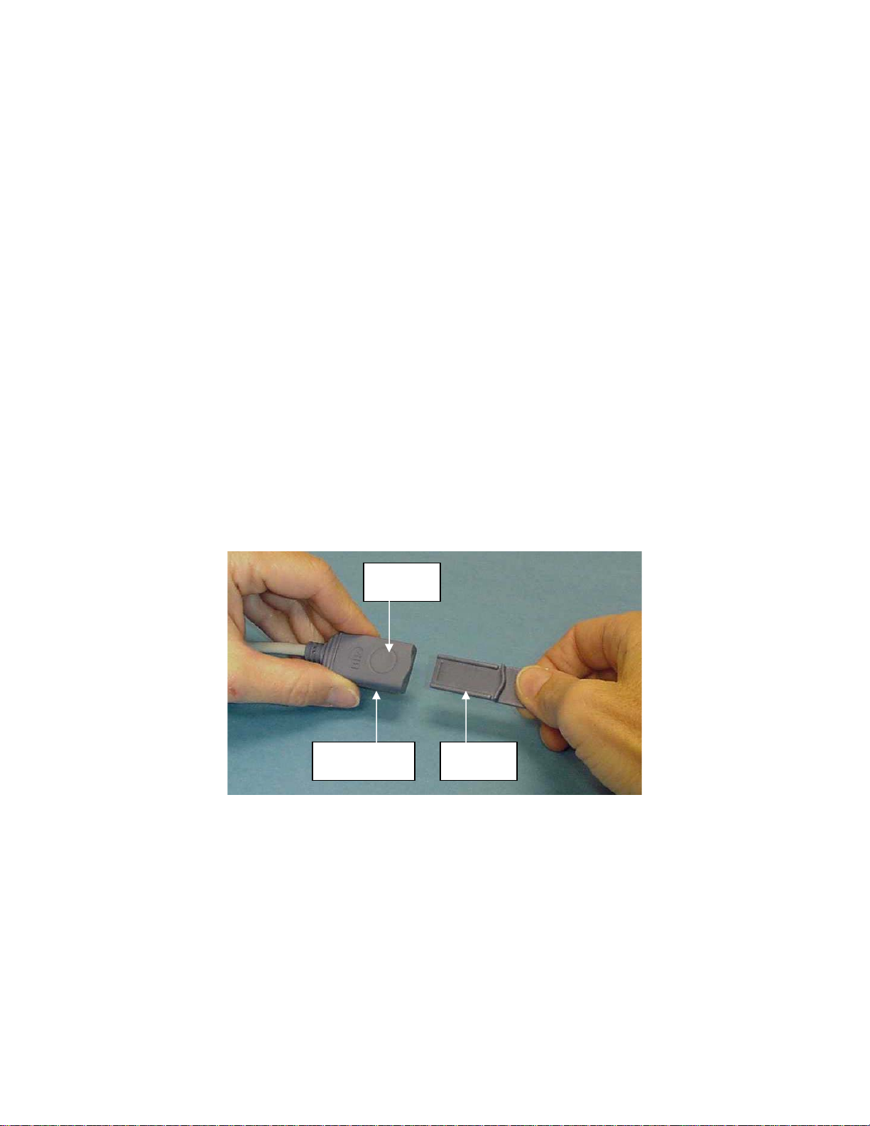
4. Attach the BIS Sensor to the PIC
Release
Button
PIC Sensor
Connector
Sensor tab
Figure 8 Connecting the PIC (BIS XP Platform and XP Compatible)
BIS XP Platform or XP Compatible: To insert the sensor into the PIC, line up as
shown and insert the sensor tab into the PIC sensor connector until an audible
“click” is heard. The blank side of the sensor tab (i.e. the side without the computer
chip) should be facing up.
Standard System: Line up the arrows and press firmly to ensure a good
connection.
For best results, use tape to secure the sensor in place. Adhesive should be used
only on the sensor, NOT on the PIC sensor connector.
3-2
Page 33
SECTION 3 OPERATING THE A-2000
______________________________________________________________________
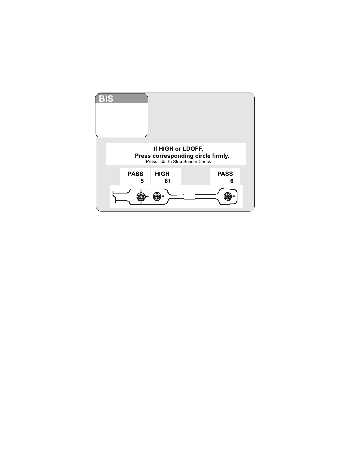
3.2 THE SENSOR CHECK AND SENSOR INTEGRITY CHECK
A Sensor Check is initiated automatically when the sensor and PIC are connected to the
DSC. It may also be initiated by the user in the Setup Menu.
Figure 9 The Sensor Check (BIS Standard and BIS Pediatric sensors)
3-3
Page 34
SECTION 3 OPERATING THE A-2000
______________________________________________________________________
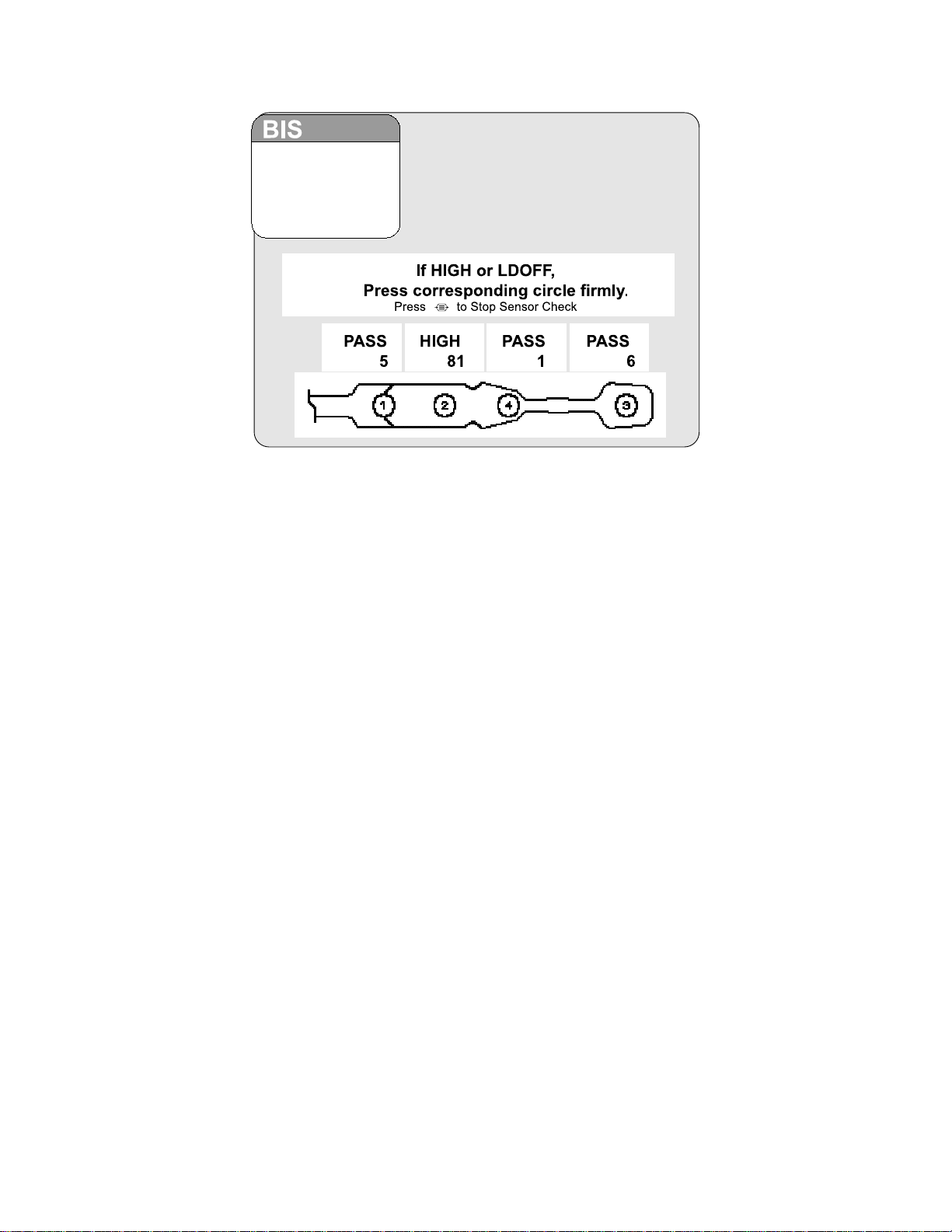
Figure 10 The Sensor Check (BIS Quatro and BIS Extend)
The impedance value for each electrode, in kilo ohms, appears on the screen along with
its status:
PASS - An electrode passes if the impedance for that electrode is less than 7.5 kilo
ohms. The ground electrode (element #2) must be less than 30 kilo ohms to pass.
HIGH - An electrode is labeled "HIGH" if its impedance value is above 7.5 kilo ohms. As
long as the combined impedance (elements #1 and #3) is less than 15 kilo ohms, the
sensor check will be considered successful. (BIS Quatro and BIS Extend also check
combined impedance of elements #1 and #4). If the combined impedance is over the 15
kilo ohms limit, you will need to re-prep the electrodes and check all connections. The
monitor will continue to check impedance until it is acceptable.
NOISE - If the signal from the electrode goes beyond the measurable range, the label
"NOISE" will appear.
LDOFF - If a lead is too loose or disconnected, the label "LDOFF" will appear.
The monitor continues updating the values until all impedance values are acceptable. To
end the impedance test, press [MENU/EXIT]. The Sensor Check impedance test must
be successfully completed before normal processing resumes.
Note:
All signal status messages will be suppressed for 60 seconds after a
sensor check has exited. This provides the time for signal quality to
recover.
The Sensor Integrity Check (BIS XP Platform only) is also initiated each time that a
sensor is connected to the PIC. It checks to make certain that a valid, unexpired sensor
is in use.
3-4
Page 35
SECTION 3 OPERATING THE A-2000
42
______________________________________________________________________
3.3 THE BIS TREND SCREEN DISPLAY
Once the sensor check has successfully completed, monitoring begins and the
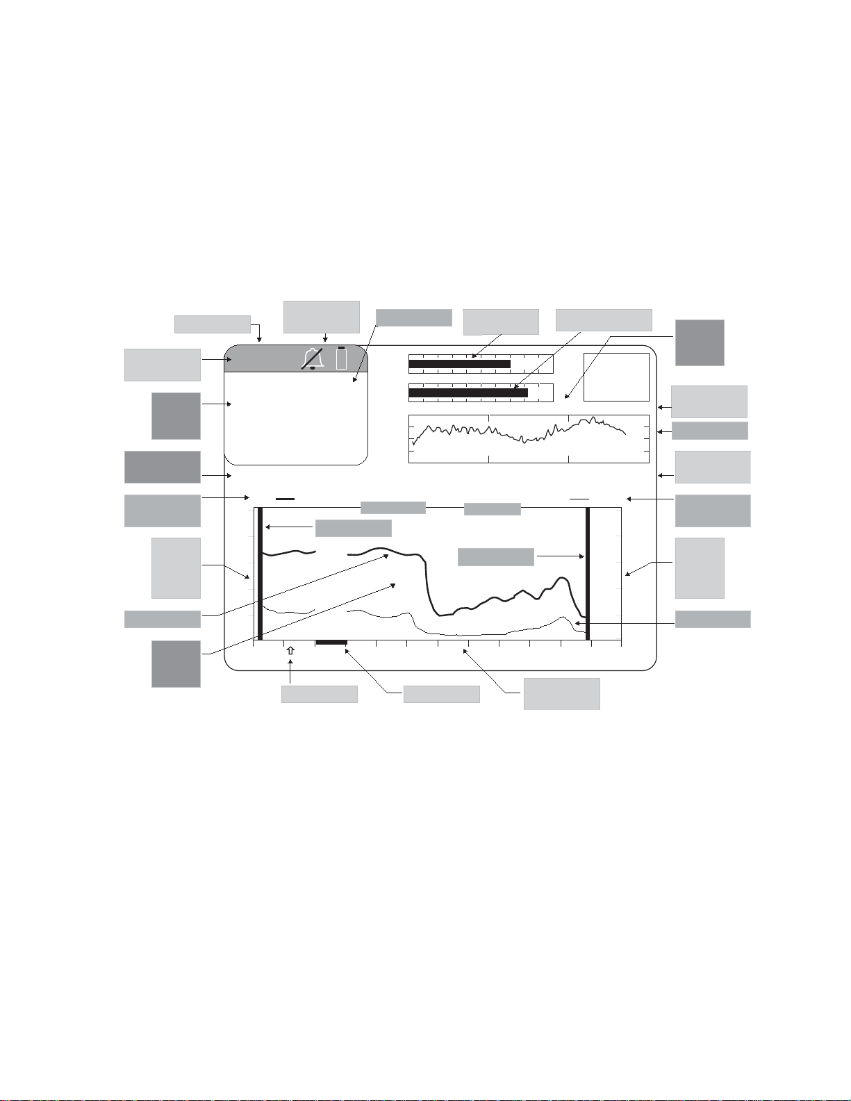
appropriate information appears on the screen. The BIS trend screen consists of four
separate regions (see Figure 11):
• The BIS Numeric Region
• The Message Region
• The Signal Quality Region
• The Graphic Display Region
BIS Name
Bar
BIS
Numeric
Region
Message
Region
Primary Trend
Legend
Primary
Trend
Vertical
Scale
BIS Name
BIS
42
MESSAGE REGION
BIS EMG
100
80
60
40
Battery & Alarm
Icons
BIS Value
SQI
-
EMG
25 mm/sec
EEG
29 Mar 2001 12:54:57 CASE: Ab9r
Date / Time
Start Case Bar
Signal Quality
Index Bar
25 0013. 10000000
Case ID
End Case Bar
Electromyograph Bar
+
SR
50
25
µv/div
80
70
60
50
Signal
Quality
Region
Sweep Speed/
Y Scale
Waveform Box
Diagnostic
Codes
Secondary Trend
Legend
Secondary
Trend
Vertical
Scale
Primary Trend
Graphic
Display
Region
20
0
12:10 12:20 12:30 12:40 12:50 13:0012:00
Event Marker Artifact Bar
Horizontal
(time) Scale
40
30
Figure 11 - Screen Regions and Features
3.3.1 The BIS (Bispectral Index) Numeric Region
The BIS Numeric Region is in the upper left corner of the screen and displays the
current numeric value of the BIS in a large, easily readable font. The number displayed
changes to outlined characters during periods of poor signal quality when SQI is below
50, and disappears altogether when signal quality is very low. If limit alarms have been
set, this number will alternately display as a solid or outlined numeric character
whenever a limit is reached. This region also displays the alarm silence icon (a slashed
bell) when the alarm silence button is activated, the battery icon (which blinks when
battery power is low) when the monitor is operating on battery power, and the message,
“EXTEND MODE ON” when a BIS Extend sensor is in use. The BIS number is
displayed and continuously updated during all display modes.
Secondary Trend
3-5
Page 36

SECTION 3 OPERATING THE A-2000
______________________________________________________________________
3.3.2 The Signal Quality Region
The Signal Quality Region is located in the upper right section of the screen. When the
[MENU/EXIT] key has been pressed, this area is used to display the Setup Menu. In the
BIS Log display, it displays instructions. In all other modes, the following signal quality
information is displayed. (Refer to Figure 11.)
3.3.2.1 The Signal Quality Index (SQI) Bar Graph
The SQI is an indication of the quality of the EEG signal that is received and processed
into screen data. The SQI graph represents a scale of 0 - 100, marked off at intervals of
10. Optimal signal quality for the EEG channel source is indicated when the bar extends
to the right side (+) of the graph.
3.3.2.2 The Electromyograph (EMG) Bar Graph
The EMG graph shows the power (in decibels) in the frequency range 70 - 110 Hz. This
frequency range contains power from muscle activity (i.e., electromyography or “EMG”)
as well as power from other high-frequency artifacts. A low level of EMG is indicated
when the bar is not present or at the left side of the graph.
3.3.2.3 The Electroencephalogram (EEG) Waveform Display
Filtered EEG waveforms are displayed with a sweep rate of 25 millimeters per second
and a scale of 25 microvolts per division (default). EEG filters can be turned off and the
sweep speed and amplitude can be changed in the Display Parameter Setup screen.
3.3.2.4 The Suppression Ratio (SR) Number
Suppression ratio is a calculated parameter to give the user an indication when an
isoelectric (flatline) condition may exist. Suppression ratio is the percentage of time over
the last 63-second period that the signal is considered to be in the suppressed state.
For example: SR=11 (isoelectric over 11% of the last 63 second review). The SR is
displayed in the upper right corner of the screen.
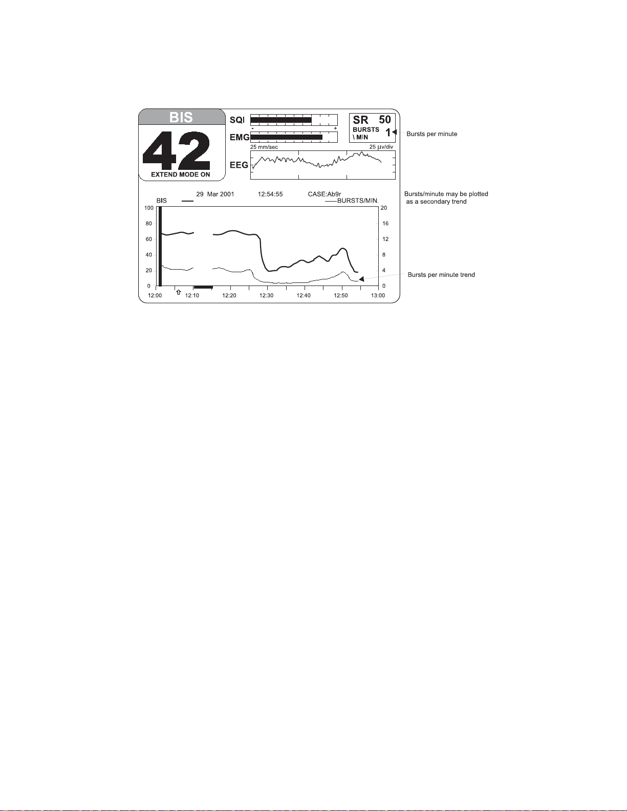
3.3.2.5 The Burst Count (BURSTS/MIN)
When a BIS Extend sensor is in use, the Burst Count is displayed just below the SR
number. Burst Count is an alternative method of quantifying suppression, reported as
the number of EEG bursts per minute. When the signal quality is low (SQI less than 15)
or when the suppression ratio is less than 5, the burst count is not displayed.
3-6
Page 37
SECTION 3 OPERATING THE A-2000
______________________________________________________________________
Figure 12 The BIS Trend Display with BIS Extend Sensor in Use
3.3.3 The Message Region
The Message Region is a space reserved for text that appears below the BIS and Signal
Quality Regions and extends the full width of the screen. Status and error messages are
displayed here. Specific error messages are explained in the Troubleshooting section of
this manual.
3.3.4 Graphic Display Region
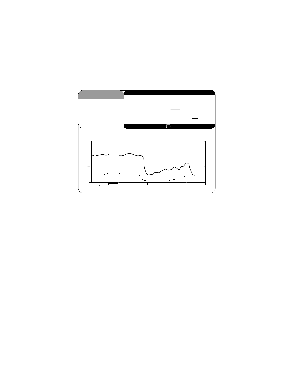
The Graphic Display Region displays trend graphs of the BIS and an optional secondary
variable. During the sensor check procedure, this region of the screen is used to issue
instructions and report current status.
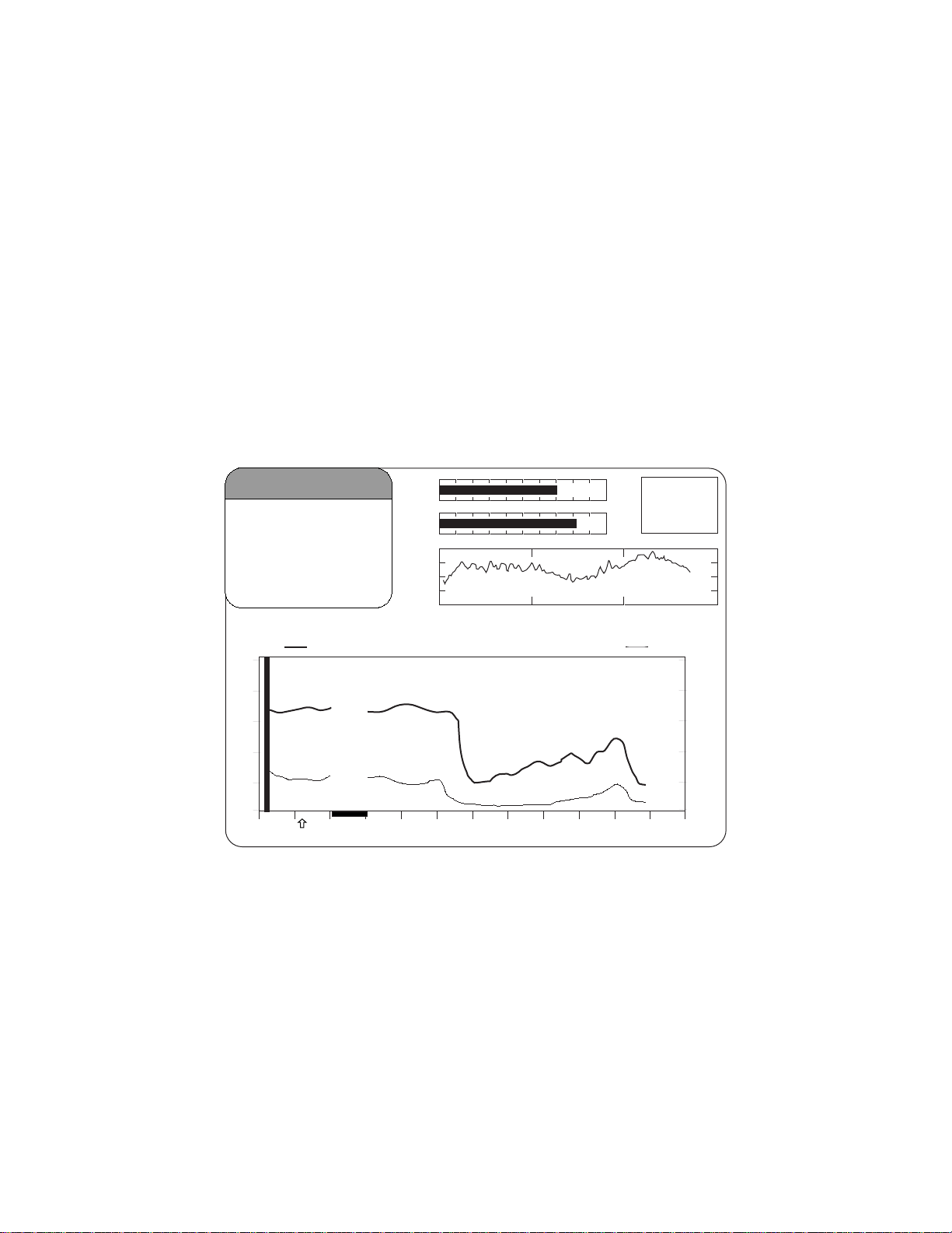
The BIS Trend display shows a plot of the Bispectral Index over a 1-hour time period.
The BIS trend is indicated with a thick line and its unit markings appear on the left axis.
The name BIS is displayed above the left corner of the graph (Figures 12,13).
A secondary variable may be added to the display by selecting "SR", "EMG," or "SQI" in
the Advanced Setup Menu. When a BIS Extend sensor is in use, you may select Burst
Count (“Bursts/Min”). See Section 3.4.2 for instructions on selecting a secondary
variable. The secondary trend is shown with a thin line and its unit markings appear on
the right axis. The secondary trend name is displayed above the right corner of the
graph.
A thick vertical bar marks the start of a case at the time a new case is detected. A
similar bar appears at the end of a case when in Review Mode or on the printer output.
The monitor assumes that a case has ended if the DSC, the PIC or the sensor have
been disconnected for more than 15 minutes, or if the monitor has been turned off, then
on.
3-7
Page 38
SECTION 3 OPERATING THE A-2000
______________________________________________________________________
During periods of poor signal quality when SQI is below 50, an artifact bar appears
along the horizontal axis at the bottom of the graph area. It appears as a hatched line.
When signal quality is considered too low to calculate a BIS value, this bar will show
prominently as solid white and any trend variables that are adversely affected by artifact
will not be displayed.
Event markers may be added to the display by pressing [MENU/EXIT], then selecting
[EVENT] from the Setup Menu. Event markers are shown as arrows at the bottom of the
Trend Display.
If alarm limits for BIS have been set in the Alarm Menu, they will appear as horizontal
dotted lines across the graph. When these limits are reached, the BIS number in the
upper left corner of the screen will alternately display as a solid or outlined numeric
character and the limit line will blink, a message will appear in the Message Region of
the screen, and a warning tone will sound (unless the [SILENCE] key has been
pressed).
BIS
4242
BIS EMG
100
80
60
40
20
0
29 Mar 2001 12:54:55 CASE:Ab9r
12:10 12:20 12:30 12:40 12:50 13:0012:00
SQI
EMG
EEG
-
25 mm/sec
+
SR
50
25
μ
v/div
80
70
60
50
40
30
Figure 13 The BIS Trend Display
3-8
Page 39
SECTION 3 OPERATING THE A-2000
______________________________________________________________________
3.4 THE A-2000 SOFTWARE MENUS AND MENU SELECTIONS
This section discusses the A-2000 software menus and menu selections, including:
• Setup Menu
• Advanced Setup Menu
• Display Parameter Setup screen
• Diagnostic Menu
• Alarm Menu
• Sensor Data Display screen
• System Configuration Menu
Details of the Diagnostic and System Configuration Menus and the Sensor Data Display
screen are covered in more detail in Section 7.
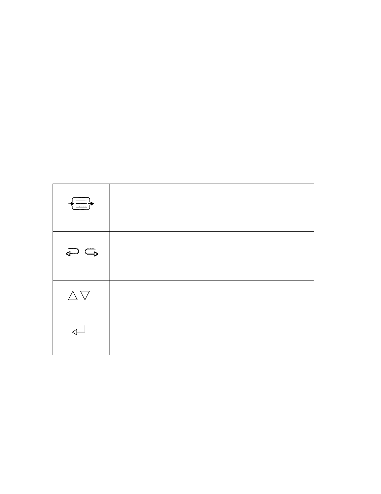
3.4.1 Menu Navigation:
The [MENU/EXIT] key is generally used to enter the Setup Menu
and to exit from all other menus. It is also used to halt certain
procedures, such as the sensor check, and to answer "no" to a
question.
The left [←] and right [→] arrow keys are generally used to enter
Review mode and to scroll data backward and forward in time. In
the BIS Log, they show the previous [←] or next [→] screen of
data.
The up [↑] and down [↓] arrows are generally used to move from
one menu selection to another.
The [SELECT] key is used to move between options within a
menu selection, to confirm an entry, and to answer "yes" to a
question.
Figure 14 Menu Navigation
When a menu is displayed, the default or set values for each line are underlined. The
line that is currently selected is highlighted, and the default or set value for that line
appears in reverse video. To move to another line, use the up [↑] or down [↓] arrows.
To select a particular menu item, or to change a selection, use the [SELECT] key.
3-9
Page 40
SECTION 3 OPERATING THE A-2000
______________________________________________________________________
3.4.2 The Setup Menu
The Setup Menu can generally be accessed by pressing the [MENU/EXIT] key. Before
using the monitor for the first time, you may want to update the Setup Menu with your
desired screen settings and the current date and time. You should also familiarize
yourself with the various menu options available. These menu options are discussed
below. For more detail on what the settings mean, refer to “The BIS Trend Screen
Display” in Section 3.3 and "Features and Capabilities" in Section 5.
BIS
4242
Event
Sensor Check
Display Type Trend DSA
BIS Smoothing Rate (secs.) 15 30
Advanced Setup
Setup Menu
Press
BIS Log EEG
to Exit
BIS EMG09 Feb 2000 12:55:02
100
80
60
40
20
0
12:10 12:20 12:30 12:40 12:50 13:0012:00
CASE:aG2c
80
70
60
50
40
30
Figure 15 Main Screen with Setup Menu and Trend Display
When the Setup Menu appears, the first selection, "Event," is highlighted.
To move from one selection to another, use the up [↑] and down [↓] arrows to
highlight the option you desire. Then follow the instructions below:
Event - This option is used during operation to mark a significant event on the screen
display and printout.
To mark an event:
1. Press [MENU/EXIT] to access the Setup Menu.
2. Press [SELECT] when Event is highlighted.
The event is immediately marked with an arrow on the time scale and the Setup Menu
automatically exits to the Main Screen.
3-10
Page 41

SECTION 3 OPERATING THE A-2000
______________________________________________________________________
Sensor Check - Sensor impedance checks are initiated automatically when the PIC and
sensor are attached to the DSC. You may initiate another check at any time by selecting
this option.
To initiate the check:
1. Press [MENU/EXIT] to access the Setup Menu.
2. Highlight Sensor Check, using the [↑] or [↓] arrows.
3. Press [SELECT].
The check may be aborted at any time by pressing [MENU/EXIT]. When the check has
been completed successfully, the screen will exit automatically. For details on the
sensor check procedure, refer to "The Sensor Check" in Section 3.2.
Display Type – Allows the user to select the display in the graphic display region from
four choices: Trend, DSA (Density Spectral Array), EEG, or BIS Log.
To change Display Type:
1. Press [MENU/EXIT] to access the Setup Menu.
2. Highlight Display Type using the up [↑] or down [↓] arrows.
3. Press [SELECT] until the desired display type appears in reverse video.
4. Press the up [↑] or down [↓] arrows to move to the next menu item, or
5. Press [MENU/EXIT] to exit.
The system always defaults to the Trend display.
BIS Smoothing Rate (secs.) - The A-2000 offers two choices of smoothing rates over
which the BIS value is averaged:
• 15 seconds (Provides increased responsiveness to state changes, such as
induction or awakening). This is the default setting unless a BIS Extend Sensor
is attached or the system is set to ICU mode.
• 30 seconds (Provides a smoother trend with decreased variability and sensitivity
to artifact). This is the default setting when a BIS Extend Sensor is attached or
when the system is set to ICU mode in the System Configuration Menu.
To change the BIS Smoothing Rate:
1. Press [MENU/EXIT] to access the Setup Menu.
2. Highlight BIS Smoothing Rate using the up [↑] or down [↓] arrows.
3. Press [SELECT] until the desired smoothing rate appears in reverse video.
4. Press the up [↑] or down [↓] arrows to move to the next menu item, or
5. Press [MENU/EXIT] to exit.
To permanently save this change, use the “Save Settings” option in the Advanced Setup
Menu.
Advanced Setup Menu
To display the Advanced Setup Menu:
1. Press [MENU/EXIT] to access the Setup Menu.
2. Highlight Advanced Setup using the up [↑] or down [
3. Press [SELECT].
↓] arrows.
3-11
Page 42
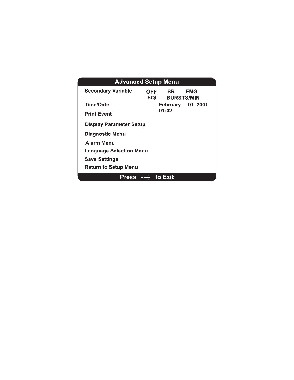
SECTION 3 OPERATING THE A-2000
______________________________________________________________________
3.4.3 The Advanced Setup Menu
The Advanced Setup Menu is used to select infrequently changed parameters. You may
need to access the Advanced Setup Menu before using the system for the first time to
set the date and time and to save any settings that were changed in the Setup Menu so
they will not be lost when the monitor is powered off. You may exit the Advanced Menu
at any time by pressing [MENU/EXIT]. Menu options are discussed below:
Figure 16 The Advanced Setup Menu
Secondary Variable - Adds a secondary trend variable to the Trend Graph:
Selecting "SR" will plot the suppression ratio.
Selecting "EMG" will plot electromyograph or high frequency signal detection.
Selecting "SQI" will plot the signal quality index.
Selecting “BURSTS/MIN” will plot the burst count. Note that this is available only when
a BIS Extend sensor is attached to the PIC. If a BIS Extend sensor is not connected,
this menu option does not appear.
To specify a secondary variable:
1. Press [MENU/EXIT] to access the Setup Menu.
2. Highlight Advanced Setup using the up [↑] or down [↓] arrows.
3. Press [SELECT].
4. Highlight Secondary Variable using the up [↑] or down [↓] arrows.
5. Press [SELECT] until the desired variable appears in reverse video.
6. Press the up [↑] or down [↓] arrows to move to the next menu item, or
7. Press [MENU/EXIT] to exit.
To permanently save this change, use the “Save Settings” option in the Advanced Setup
Menu.
3-12
Page 43

SECTION 3 OPERATING THE A-2000
______________________________________________________________________
Time/Date
To set the current time and date:
1. Press [MENU/EXIT] to access the Setup Menu.
2. Highlight Advanced Setup using the up [↑] or down [↓] arrows.
3. Press [SELECT].
4. Highlight Time/Date using the up [↑] or down [↓] arrows.
5. Press [SELECT] until the date or time value you wish to update appears in
reverse video.
6. Use the up [↑] or down [↓] arrows to increase or decrease the values displayed.
7. Press [SELECT] to move to the next date or time value.
8. To save the date or time changes, press [SELECT] at the last Time/Date option
(minutes). Pressing [Menu/Exit] before this last option aborts previous changes.
9. Press [MENU/EXIT] to exit from the Advanced Setup Menu.
Note:
The time/date is initially set for the Eastern Standard Time zone (USA). It
will be necessary for you to change the time twice per year using the
Time/Date feature if you are located in a time zone that alters its clocks at
the beginning or end of Daylight Savings Time.
When a time/date is entered that is earlier than the current time/date in
the monitor, all data memory will be erased. The prompt, "Clear Data
Memory?" will appear to alert you of this. Press [SELECT] to confirm, or
press [MENU/EXIT] to abort.
Print Event - Prints all available data on the most recent marked event.
To print an event:
1. Press [MENU/EXIT] to access the Setup Menu.
2. Highlight Advanced Setup using the up [↑] or down [↓] arrows.
3. Press [SELECT].
4. Highlight Print Event using the up [↑] or down [↓] arrows.
5. Press [SELECT].
Display Parameter Setup – Allows the user to turn filters OFF or ON, change the EEG
sweep speed and amplitude settings, and change the default BIS Log recording interval.
To access the Display Parameter Setup screen:
1. Press [MENU/EXIT] to access the Setup Menu.
2. Highlight Advanced Setup using the up [↑] or down [↓] arrows.
3. Press [SELECT].
4. Highlight Display Parameter Setup using the up [↑
5. Press [SELECT].
The Display Parameter Setup options are discussed in section 3.4.3.
Diagnostic Menu
To display the Diagnostic Menu:
1. Press [MENU/EXIT] to access the Setup Menu.
] or down [↓] arrows.
3-13
Page 44

SECTION 3 OPERATING THE A-2000
______________________________________________________________________
2. Highlight Advanced Setup using the up [↑] or down [↓] arrows.
3. Press [SELECT].
4. Highlight Diagnostic Menu using the up [↑] or down [↓] arrows.
5. Press [SELECT].
Use of the Diagnostic Menu is covered in Section 7, "Diagnostics and Troubleshooting".
Alarm Menu – Allows the user to set the BIS high and low limit alarms.
To display the Alarm Menu:
1. Press [MENU/EXIT] to access the Setup Menu.
2. Highlight Advanced Setup using the up [↑] or down [↓] arrows.
3. Press [SELECT].
4. Highlight Alarm Menu using the up [↑] or down [↓] arrows.
5. Press [SELECT].
The Alarm Menu options are discussed in section 3.4.6.
3-14
Page 45

SECTION 3 OPERATING THE A-2000
______________________________________________________________________
Language Selection Menu – The A-2000 is designed to support multiple languages.
To display the Language Selection Menu:
1. Press [MENU/EXIT] to access the Setup Menu.
2. Highlight Advanced Setup using the up [↑] or down [↓] arrows.
3. Press [SELECT].
4. Highlight Language Selection Menu using the up [↑] or down [↓] arrows.
5. Press [SELECT].
The Language Selection Menu options are discussed in section 3.4.7.
Save Settings - The A-2000 monitor will always power up configured to settings that
have been saved in memory.
To save the current configuration settings:
1. Press [MENU/EXIT] to access the Setup Menu.
2. Highlight Advanced Setup using the up [↑] or down [↓] arrows.
3. Press [SELECT].
4. Highlight Save Settings using the up [↑] or down [↓] arrows.
5. Press [SELECT] to save setting changes. The current settings will be saved and
the system will exit to the Main Screen.
Notes:
The Save Settings option is disabled when in Battery Backup-Low Power
condition.
Impedance checking always returns to ON and Display Type returns to
Trend after the monitor has been powered down.
Return to Setup Menu - Returns to the previous menu.
1. Press the up [↑] or down [↓] arrows to highlight Return to Setup Menu.
2. Press [SELECT] to re-display the Setup Menu.
3-15
Page 46

SECTION 3 OPERATING THE A-2000
______________________________________________________________________
3.4.4 Display Parameter Setup
This menu allows the user to view or change basic system parameters.
Display Parameter Setup
Dual EEG Display OFF ON
Filters OFF ON
EEG Sweep Speed
15 25 30
(mm/sec)
EEG Amplitude
5 10 25 50 100
(uv/div)
BIS Log Interval
1 5 15 60
(minutes)
Return to Advanced Setup Menu
to ExitPress
Figure 17 The Display Parameter Setup screen
Dual EEG Display – This option displays only when a BIS Quatro or a BIS Extend
sensor is connected. When Dual EEG Display is turned ON, the Signal Quality Region
of the screen displays an additional channel of EEG that can be used for equipment
troubleshooting purposes.
To display dual EEG waveform charts:
1. Press [MENU/EXIT] to access the Setup Menu.
2. Highlight Advanced Setup using the up [↑] or down [↓] arrows.
3. Press [SELECT].
4. Highlight Display Parameter Setup using the up [↑] or down [↓] arrows.
5. Press [SELECT].
6. Highlight Dual EEG Display using the up [↑] or down [↓] arrows.
7. Press [SELECT] until ON appears in reverse video.
8. Press the up [↑] or down [↓] arrows to move to the next menu item, or
9. Press [MENU/EXIT] to exit.
To permanently save this change, use the “Save Settings” option in the Advanced Setup
Menu.
3-16
Page 47

SECTION 3 OPERATING THE A-2000
______________________________________________________________________
Filters - The A-2000 uses filters to screen out undesirable interference from the raw
EEG signal display. If you prefer to observe the raw EEG without the filters, they may be
turned off.
To turn the Filters off:
1. Press [MENU/EXIT] to access the Setup Menu.
2. Highlight Advanced Setup using the up [↑] or down [↓] arrows.
3. Press [SELECT].
4. Highlight Display Parameter Setup using the up [↑] or down [↓] arrows.
5. Press [SELECT].
6. Highlight Filters using the up [↑] or down [↓] arrows.
7. Press [SELECT] until OFF appears in reverse video.
8. Press the up [↑] or down [↓] arrows to move to the next menu item, or
9. Press [MENU/EXIT] to exit.
To permanently save this change, use the “Save Settings” option in the Advanced Setup
Menu.
EEG Sweep Speed mm/sec – Allows the user to change the EEG sweep speed to 15,
25, or 30 mm/second.
To change the EEG Sweep Speed:
1. Press [MENU/EXIT] to access the Setup Menu.
2. Highlight Advanced Setup using the up [↑] or down [↓] arrows.
3. Press [SELECT].
4. Highlight Display Parameter Setup using the up [↑] or down [↓] arrows.
5. Press [SELECT].
6. Highlight EEG Sweep Speed using the up [↑] or down [↓] arrows.
7. Press [SELECT] until the desired sweep speed appears in reverse video.
8. Press the up [↑] or down [↓] arrows to move to the next menu item, or
9. Press [MENU/EXIT] to exit.
To permanently save this change, use the “Save Settings” option in the Advanced Setup
Menu.
EEG Amplitude
amplitude to 5, 10, 25, 50, or 100 μV/div.
To change the EEG Amplitude:
1. Press [MENU/EXIT] to access the Setup Menu.
2. Highlight Advanced Setup using the up [↑] or down [↓] arrows.
3. Press [SELECT].
4. Highlight Display Parameter Setup using the up [↑] or down [↓] arrows.
5. Press [SELECT].
6. Highlight EEG Amplitude using the up [↑] or down [↓] arrows.
7. Press [SELECT] until the desired EEG amplitude appears in reverse video.
8. Press the up [↑] or down [↓] arrows to move to the next menu item, or
9. Press [MENU/EXIT] to exit.
To permanently save this change, use the “Save Settings” option in the Advanced Setup
Menu.
μv/div – (Display Type - EEG only) Allows the user to change the EEG
3-17
Page 48

SECTION 3 OPERATING THE A-2000
______________________________________________________________________
BIS Log Interval (minutes) – The interval at which the BIS values are reported in the
BIS Log display can be set to 1, 5, 15, or 60 minutes.
To set the BIS Log Interval:
1. Press [MENU/EXIT] to access the Setup Menu.
2. Highlight Advanced Setup using the up [↑] or down [↓] arrows.
3. Press [SELECT].
4. Highlight Display Parameter Setup using the up [↑] or down [↓] arrows.
5. Press [SELECT].
6. Highlight BIS Log Interval (minutes) using the up [↑] or down [↓] arrows.
7. Press [SELECT] until the desired interval appears in reverse video.
8. Press the up [↑] or down [↓] arrows to move to the next menu item, or
9. Press [MENU/EXIT] to exit.
Alternatively, when BIS Log display is active, press the up [↑] or down [↓] arrows to
increase or decrease the interval, respectively.
To permanently save this change, use the “Save Settings” option in the Advanced Setup
Menu. When ICU Mode is selected or when a BIS Extend sensor is attached, BIS Log
interval is automatically set to 60 minutes.
Return to Advanced Setup Menu - Returns to the previous menu.
1. Press the up [↑] or down [↓] arrows to highlight Return to Advanced Setup
Menu.
2. Press [SELECT] to re-display the Advanced Setup Menu.
3.4.5 The Diagnostic Menu
The Diagnostic Menu is covered in detail in Section 7.
3.4.6 Alarm Menu
Alarm Menu
High Alarm Limit OFF
Low Alarm Limit OFF
Alarm Suspend ON OFF
Return to Advanced Setup Menu
to ExitPress
Figure 18 The Alarm Menu
3-18
Page 49

SECTION 3 OPERATING THE A-2000
______________________________________________________________________
High Alarm Limit - A high alarm limit may be set so that you are notified when the BIS
number reaches a particular high level. If the BIS number reaches the high limit, the BIS
number displayed on the screen will alternate from a solid display to an outlined display
(when signal quality is good). If signal quality goes below 50, the outlined BIS number
will blink on and off. The limit line shown on the graphic display will also blink. An alarm
message appears and, if alarms have not been silenced, an audible alarm will sound.
To set the high alarm limit:
1. Press [MENU/EXIT] to access the Setup Menu.
2. Highlight Advanced Setup using the up [↑] or down [↓] arrows.
3. Press [SELECT].
4. Highlight Alarm Menu using the up [↑] or down [↓] arrows.
5. Press [SELECT].
6. Highlight High Alarm Limit.
7. Press [SELECT].
8. Use the up [↑] or down [↓] arrows to increase or decrease the limit number.
9. Press [SELECT] to confirm the setting.
10. Press [MENU/EXIT] to exit the Alarm Menu.
Note:
Turning a limit alarm OFF differs from pressing the front panel [SILENCE]
in that OFF disables audible and visible alarms for the BIS alarm limit
only. The Alarm Silence key disables all audible alarms but does not
disable visual alarms.
To permanently save this change, use the “Save Settings” option in the Advanced Setup
Menu.
Low Alarm Limit - A low alarm limit may be set so that you are notified when the BIS
number reaches a particular low level. If the BIS number descends to the low limit, the
BIS number displayed on the screen will alternate from a solid display and outlined
display (when signal quality is good). If signal quality is below 50, the outlined BIS
number will blink on and off. The limit line shown on the graphic display will also blink.
An alarm message appears and, if alarms have not been silenced, an audible alarm will
sound.
To set the low alarm limit:
1. Press [MENU/EXIT] to access the Setup Menu.
2. Highlight Advanced Setup using the up [↑] or down [↓] arrows.
3. Press [SELECT].
4. Highlight Alarm Menu using the up [↑] or down [↓] arrows.
5. Press [SELECT].
6. Highlight Low Alarm Limit.
7. Press [SELECT].
8. Use the up [↑
9. Press [SELECT] to confirm the setting.
10. Press [MENU/EXIT] to exit the Alarm Menu.
] or down [↓] arrows to increase or decrease the limit number.
3-19
Page 50

SECTION 3 OPERATING THE A-2000
______________________________________________________________________
Note:
Turning a limit alarm OFF differs from pressing the front panel [SILENCE]
in that OFF disables audible and visible alarms for the BIS alarm limit
only. The Alarm Silence key disables all audible alarms but does not
disable visual alarms.
To permanently save this change, use the “Save Settings” option in the Advanced Setup
Menu.
Alarm Suspend – This option, when set to ON, automatically disables alarm silencing
after 2 minutes. Alarm suspend is automatically activated when a BIS Extend Sensor is
in use or when ICU mode is on.
To change the Alarm Silence button to suspend (rather than cancel) the audible alarm:
1. Press [MENU/EXIT] to access the Setup Menu.
2. Highlight Advanced Setup using the up [↑] or down [↓] arrows.
3. Press [SELECT].
4. Highlight Alarm Menu using the up [↑] or down [↓] arrows.
5. Press [SELECT].
6. Highlight Alarm Suspend.
7. Press [SELECT] until ON appears in reverse video.
8. Press [MENU/EXIT] to exit the Alarm Menu.
To permanently save this change, use the “Save Settings” option in the Advanced Setup
Menu.
Return to Advanced Setup Menu - Returns to the previous menu.
1. Press the up [↑] or down [↓] arrows to highlight Return to Advanced Setup
Menu.
2. Press [SELECT] to re-display the Advanced Setup Menu.
3-20
Page 51
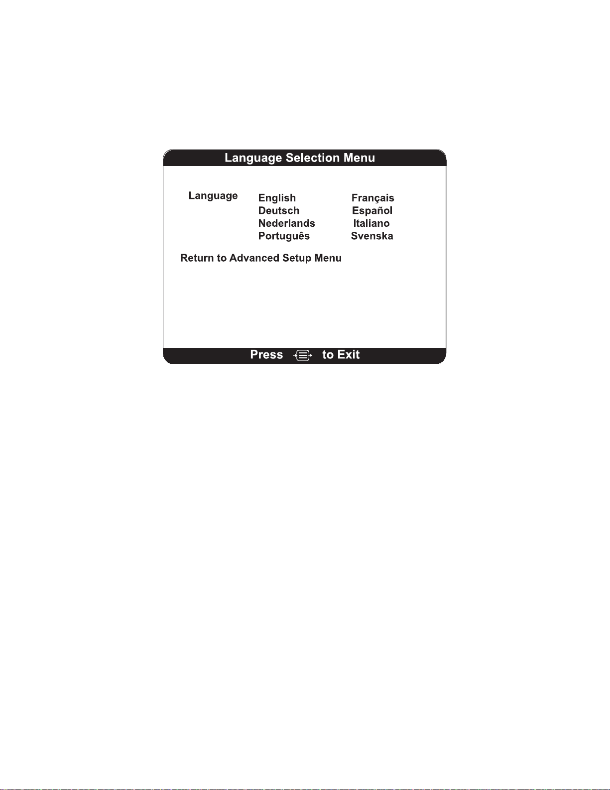
SECTION 3 OPERATING THE A-2000
______________________________________________________________________
3.4.7 Language Selection Menu
The A-2000 is designed to support multiple languages.
Figure 19 The Language Selection Menu
To change languages:
1. Press [MENU/EXIT] to access the Setup Menu.
2. Highlight Advanced Setup using the up [↑] or down [↓] arrows, then press
[SELECT].
3. Highlight Language Selection Menu using the up [↑] or down [↓] arrows.
4. Press [SELECT]. A new menu screen will display listing the language choices.
5. Press [SELECT] until the desired language is selected.
6. Use the up [↑] or down [↓] arrows to highlight Return to Advanced Setup Menu
and press [SELECT]. This will redisplay the Advanced Setup Menu in the
selected language.
7. To make sure that the selected language displays every time the monitor is
turned on, use the arrows to highlight Save Settings, then press [SELECT] to
save setting changes.
Return to Advanced Setup Menu - Returns to the previous menu.
1. Press the up [↑] or down [↓] arrows to highlight Return to Advanced Setup
Menu.
2. Press [SELECT] to re-display the Advanced Setup Menu.
3.4.8 Sensor Data Display Screen And System Configuration Menu
The Sensor Data Display screen and System Configuration Menu are covered under the
Diagnostic Menu in Section 7, "Diagnostics and Troubleshooting".
3-21
Page 52
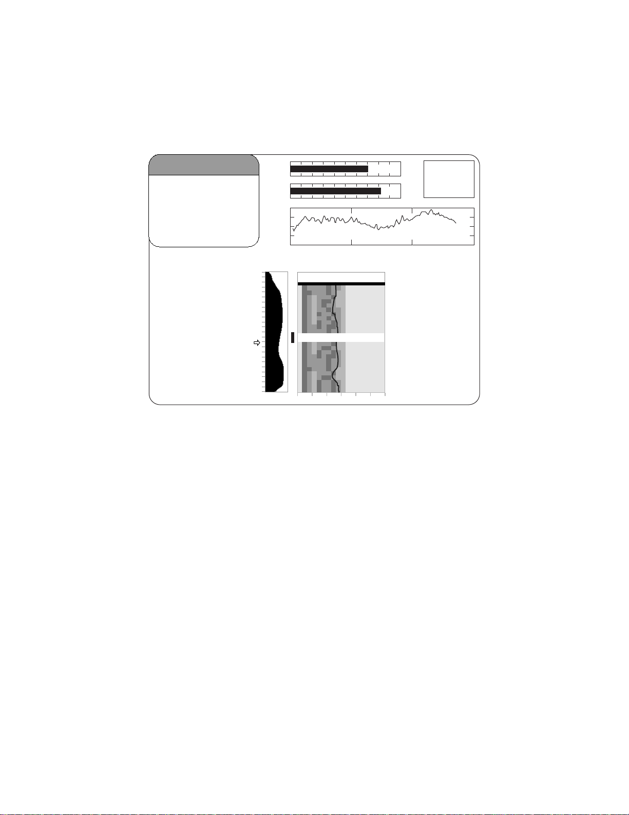
SECTION 3 OPERATING THE A-2000
______________________________________________________________________
3.5 ALTERNATIVE DISPLAYS
Alternative screen displays can be requested in the Setup Menu. These displays are:
DSA, EEG and BIS Log.
BIS
4242
Figure 20 The Density Spectral Array (DSA) Display
SQI
-
EMG
25 mm/sec
EEG
29 Mar 2001 13:01:52 CASE:Ab9r
AMPL
12:57
12:58
12:59
13:00
13:01
SEF: 17.2
010 2030
+
SR
50
25
μ
v/div
3.5.1 The DSA Display:
The Density Spectral Array is displayed in the Graphic Display Region if the user has
selected "Display Type DSA" in the Setup Menu.
Density Spectral Array (DSA) shows changes in the power spectrum distribution over
time. The DSA is plotted using absolute spectra with a power scale of 0.0625 - 4 µV.
The frequency scale is shown on the horizontal axis with a range from 0 - 30 Hz.
A 95% spectral edge marker (actually three vertical lines: white/black/white) is
superimposed on the DSA spectra and the current spectral edge frequency value
(SEF) appears above the total power graph.
A graph of total power, indicating the strength of the signal based on a decibel (dB)
scale, is shown beside the DSA and is labeled "AMPL"(amplitude).
A thick horizontal bar marks the start of a case at the time a new case is detected. A
similar bar appears at the end of a case on the printer output. The monitor assumes
that a case has ended if the DSC, the PIC, or the sensor have been disconnected for
more than 10 minutes, or if the monitor has been turned off, then on.
3-22
Page 53
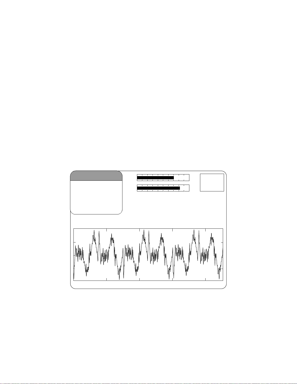
SECTION 3 OPERATING THE A-2000
______________________________________________________________________
During periods of poor signal quality (below 50), hatched artifact bars appear between
the DSA and AMPL graphs. When signal quality is too low for BIS, these bars will show
prominently as solid white and the DSA, total power, and spectral edge information will
not be displayed.
Event markers may be added to the display by pressing [MENU/EXIT], then selecting
[EVENT] from the Setup Menu. Event markers are shown as arrows next to the time
scale markers.
When the user has set alarm limits in the Alarm Menu and these limits have been
reached, the BIS number in the upper left corner of the screen will alternately display as
a solid or outlined numeric character or blink depending on the signal quality, a message
will appear in the Message Region of the screen, and a warning tone will sound (unless
the [SILENCE] key has been pressed).
3.5.2 The EEG Display
This display is a larger version of the EEG waveform display in the signal quality region.
Filtered EEG waveforms are displayed with a sweep rate of 25 millimeters per second
and a scale of 25 microvolts per division (default). EEG filters can be turned off and the
sweep speed and amplitude can be changed in the Display Parameter Setup screen.
BIS
SQI
EMG
-
+
SR
50
4242
μ
v/div
25 mm/sec
09 Feb 2000 12:55:02
Figure 21 The EEG Display
Case: Af40
25
3-23
Page 54
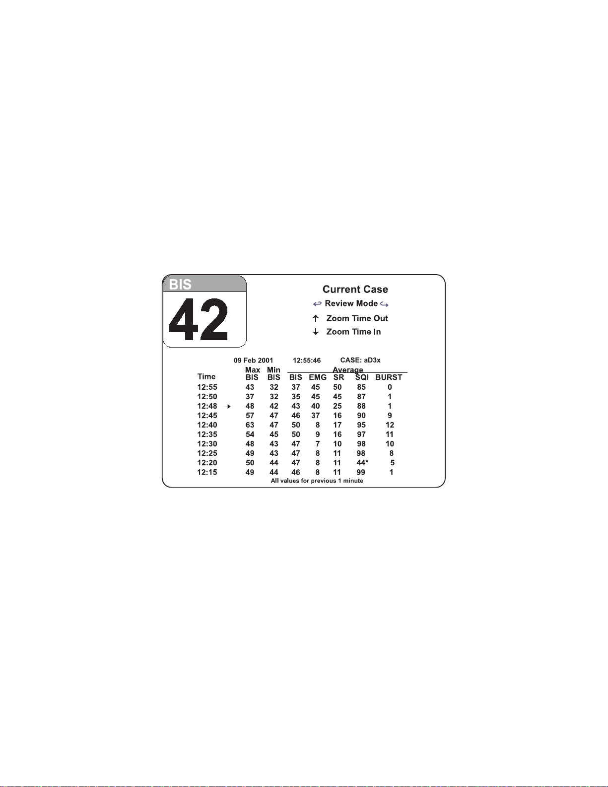
SECTION 3 OPERATING THE A-2000
______________________________________________________________________
3.5.3 The BIS Log Display
This display shows the BIS numeric values over time (up to 400 hours) and is updated
continually as each value is calculated. Each line shows a one-minute sample of the
minimum and maximum BIS values along with the average BIS, EMG, SR (Suppression
Ratio), SQI (Signal Quality Index), and BURST (Burst Count) values during the previous
one-minute period. Event markers (arrows) display when an event is noted. When
signal quality is very low, BIS, SR and Burst Count values are not reported. Note that
Burst Count is available only when a BIS Extend sensor is in use.
The time interval at which the BIS is reported can be set to 1, 5, 15, or 60 minutes in the
Display Parameter screen. A 1-minute interval is recommended for a complete picture
of the BIS over time.
Figure 22 The BIS Log Display – Current Case
3-24
Page 55
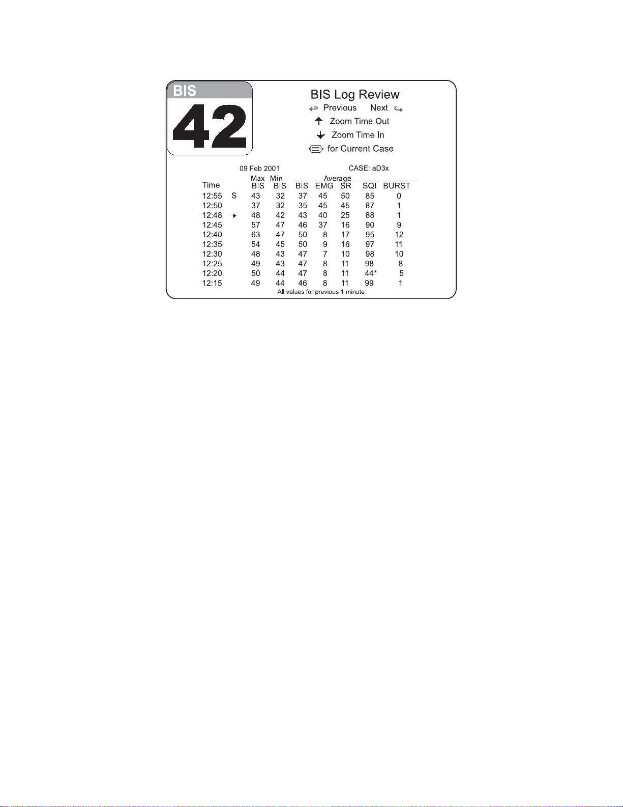
SECTION 3 OPERATING THE A-2000
______________________________________________________________________
Figure 23 The BIS Log Display – Review Mode
Previous / Next: Use the left [←] arrow on the keypad to display the previous screen of
data (earlier times). Use the right [→] arrow key to view the next screen of data (later
times).
Zoom Time Out / In: Use the up [↑] arrow on the keypad to increase the time interval at
which data are reported. Use the down [↓] arrow key to decrease the time interval.
Note:
Larger time intervals (5, 15, or 60 minutes) still report data from a oneminute sample. For example, in the figure above, 63 is the maximum BIS
recorded from 12:39:01 through 12:40:00. A one-minute interval is
recommended for continuous reporting of any changes in BIS values.
The one-minute sample containing a marked event is always displayed.
[MENU/EXIT]: In Current Case Mode, press the Menu/Exit key to display the Setup
Menu. In Review Mode, press the Menu/Exit key to display the current case. When the
Setup Menu is displayed, pressing the Menu/Exit key replaces the menu with the current
case BIS Log screen instructions.
The date, current time, and Case ID are reported at the top of the current case BIS Log
display. In Review Mode, the date and Case ID are displayed. For each time, the
following information is displayed:
Time: The time at which the sample was taken. If an event was marked at that time,
an event marker (→) is displayed at the next whole minute. (For example, in the figure
above, an event that was marked at 12:47:12 is displayed on the 12:48 line.)
3-25
Page 56

SECTION 3 OPERATING THE A-2000
______________________________________________________________________
Max BIS: The maximum value for BIS during the previous minute. For example, if the
time listed is 09:00, the maximum value recorded from 8:59:01 through 09:00:00 is
displayed.
Min BIS: The minimum value for BIS during the previous minute.
Average BIS, EMG, SR, SQI, BURST: The average values for BIS, EMG, Suppression
Ratio, Signal Quality Index and Burst Count during the previous minute. (Note that Burst
Count is available only when a BIS Extend sensor is in use.) When signal quality is poor
(below 50), an asterisk (*) is displayed next to the SQI value. When signal quality is very
low, the BIS, SR, and Burst Count values are not reported.
The following indicators display with the appropriate line:
S – Start of case
E – End of case
T – The TIME/DATE has been changed in the Advanced Setup Menu.
→ - Event marked within previous minute.
Printed reports: When a printer is available, the BIS Log data for the displayed case
may be printed by pressing the “PRINT” key.
The BIS numeric display for the current procedure will continue to be updated and
parameter alarms will continue to be announced during BIS Log display.
3-26
Page 57
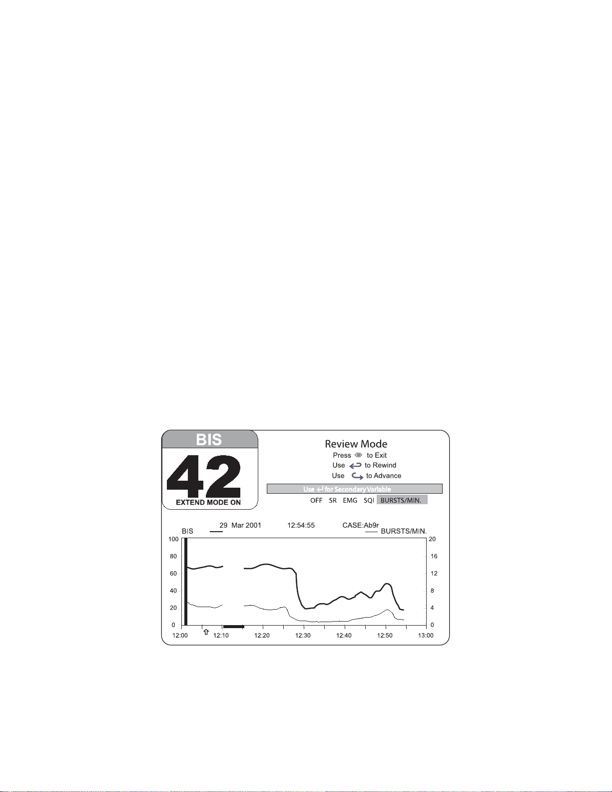
SECTION 3 OPERATING THE A-2000
______________________________________________________________________
3.6 REVIEWING STORED TREND DATA
Up to 11 hours of trend information may be viewed in Review Mode. (See Figure 24).
To review information, press the left [←] or right [→] arrow key. The Signal Quality
Region of the screen will indicate that you have entered Review Mode. Use the left [←]
arrow to advance the display backward in time, or the right [→] arrow key to advance
forward in time.
The Review Mode screen allows the user to select a secondary trend for display. Use
the [SELECT] key to highlight the secondary trend you want to display.
When the printer is available, you may print screen data. First find the case you want to
print using the REVIEW mode features then press the [PRINT] key on the printer. The
currently displayed case will be printed. DSA and EEG display data are not stored and
cannot be displayed.
Note:
When the system is using battery power, the printer is disabled to
conserve power. Stored data are retained even after the battery is
discharged.
The BIS numerical display for the current procedure will continue to be updated and
parameter alarms will continue to be announced during Review Mode.
To return to the main display, press [MENU/EXIT].
Figure 24 Main Screen with Trend Review
3-27
Page 58

SECTION 3 OPERATING THE A-2000
______________________________________________________________________
3.7 ENDING A CASE
When the case has finished:
• Disconnect the patient sensor from the PIC:
Standard system: Grasp the connectors firmly and pull. DO NOT pull apart by
the cable wires.
BIS XP Platform/ XP Compatible: Press the release button on the connector
and pull the connectors apart. DO NOT pull apart by the cable wires.
• Remove BIS Sensor from patient.
• Be sure to leave the PIC with the monitor so that it is not inadvertently discarded.
• If this is the last procedure of the day, press the button on the right side of the
monitor to turn the power OFF.
WARNING!
SHOCK HAZARD: DO NOT ATTEMPT TO DISCONNECT THE
POWER CORD WITH WET HANDS. MAKE CERTAIN THAT YOUR
HANDS ARE CLEAN AND DRY BEFORE TOUCHING THE POWER
CORD.
3.8 DATA TRANSFER
BIS values and other EEG data may be acquired from the monitor using the RS-232
serial port. Please contact Aspect Medical Systems for instructions. (See back cover for
contact information.)
3-28
Page 59

SECTION 3 OPERATING THE A-2000
______________________________________________________________________
3.9 SOFTWARE UPDATES
The A-2000 monitor will automatically begin a software update if a software update
device, attached to the serial port, is detected when the monitor power is turned on.
Follow these steps to perform the update:
1. Before attempting an update, be sure to record your institution’s saved settings,
as they will be erased during the update procedure. If a printer is connected,
access any menu and press [PRINT].
2. With the power off, connect the updating device to the Serial port at the rear of
the monitor.
3. Turn the power on. As soon as the updating device is detected, the message
“Software Update Device Detected” appears on the screen.
4. Press [SELECT] to initiate the update. (Press [MENU/EXIT] to skip update and
the monitor will operate with the current software.) The update begins, and the
message “Software Update In Progress. Do NOT Disconnect Software Update
Device” appears. When the update is complete, the message “Software Update
Successful” appears.
5. Disconnect software update device, then press [MENU/EXIT] to resume normal
operation.
6. Re-enter your saved settings and save them in the Advanced Setup Menu.
Note:
When software is upgraded, all monitor configuration settings will be lost.
Additionally, previously recorded data may be lost. Therefore,
configuration settings and previous data should be recorded before the
software update is performed.
3-29
Page 60

SECTION 3 OPERATING THE A-2000
______________________________________________________________________
3-30
Page 61

SECTION 4 QUICK REFERENCE GUIDE
______________________________________________________________________
SECTION 4
4 QUICK REFERENCE GUIDE
This “Quick Reference Guide” is intended only as an operating checklist for users
already familiar with the A-2000 BIS Monitor. Do not proceed unless you have read the
“Important Safety Precautions” (Section 1 of this manual).
BASIC OPERATION
If the A-2000 has already been installed, but has been turned off (after a previous
surgery, for example), proceed as follows:
1. Verify that all power and other cables are connected properly.
• The DSC’s long cable to the DSC port on the monitor.
• The Patient Interface Cable to the short “DSC pigtail” extending from the DSC
unit.
2. Press the button on the right side of the monitor to turn the power on. The
system will initiate a self-test to ensure that all equipment is operating properly.
3. Prepare sensor site and place BIS Sensor on the patient in accordance with
manufacturer’s instructions.
4. Using the attachment clip, secure the DSC to a convenient location near the
patient’s head.
5. Insert the BIS Sensor tab into the PIC connector until fully engaged.
You are now ready to begin monitoring. A list of features and how to find them follows,
for those familiar with operation. For detailed operating instructions and software
configuration, read Sections 2 and 3. Current settings may be viewed at any time by
viewing the appropriate menu. (See chart on next page.)
4-1
Page 62

SECTION 4 QUICK REFERENCE GUIDE
______________________________________________________________________
If you want to: Do this:
• Mark an event
• Initiate a sensor check
• Change the display type
• Change the BIS Smoothing Rate
• Access the Advanced Setup Menu
• Change the secondary variable
• Adjust the time or date
• Print data from an event
• Display the Parameter Setup
• Access the Diagnostic Menu
• Access the Alarm Menu
• Access the Language Selection Menu
• Save settings
• Display a second channel of EEG (BIS
Quatro and BIS Extend sensors only)
• Turn the EEG filters OFF
• Change the EEG sweep speed
• Change the EEG amplitude
• Change the default BIS Log interval
• Test the DSC
• Test the screen display
• View sensor data
• Clear data
• Display diagnostic codes
• Disable continuous impedance check
• Access the System Configuration Menu
• Find the software revision number,
serial number, or other data
• Set BIS limit alarms
• Change the Alarm Silence button to
suspend alarm silence after 2 minutes.
• Press [MENU/EXIT] from the Main
Screen to get to the Setup Menu.
• Use the arrows to highlight your choice.
• Press [SELECT].
• Press [MENU/EXIT] from the Main
Screen to get to the Setup Menu, then
select Advanced Setup Menu.
• Use the arrows to highlight your choice.
• Press [SELECT].
• Press [MENU/EXIT] from the Main
Screen to get to the Setup Menu, then
select Advanced Menu.
• From the Advanced Menu, select
Display Parameter Setup.
• Use the arrows to highlight your choice
• Press [SELECT].
• Press [MENU/EXIT] from the Main
Screen to get to the Setup Menu, then
select Advanced Setup Menu.
• From the Advanced Setup Menu, select
the Diagnostic Menu.
• Use the arrows to highlight your choice
• Press [SELECT].
• Press [MENU/EXIT] from the Main
Screen to get to the Setup Menu, then
select Advanced Setup Menu.
• From the Advanced Setup Menu, select
the Alarm Menu.
• Use the arrows to highlight your choice
• Press [SELECT].
4-2
Page 63

SECTION 4 QUICK REFERENCE GUIDE
______________________________________________________________________
If you want to: Do this:
• Change the serial port protocol
• Enable / disable extended memory
recording
• Change the monitor to ICU mode
• Press [MENU/EXIT] from the Main
Screen to get to the Setup Menu, then
select Advanced Setup Menu.
• From the Advanced Setup Menu, select
the Diagnostic Menu.
• From the Diagnostic Menu, select the
System Configuration Menu.
• Use the arrows to highlight your choice
• Press [SELECT].
4-3
Page 64

SECTION 4 QUICK REFERENCE GUIDE
______________________________________________________________________
4-4
Page 65

SECTION 5 FEATURES AND CAPABILITIES
______________________________________________________________________
SECTION 5
5 FEATURES AND CAPABILITIES
____________________________________________________
INTRODUCTION
This section includes:
• How the A-2000 BIS Monitoring System works
• Display Configurations
• Other System Features
5.1 HOW THE A-2000 MONITORING SYSTEM WORKS
A sensor placed on the patient’s head transmits EEG signals to the Digital Signal
Converter. The DSC amplifies and digitizes these signals, then sends them to the
monitor. The monitor software filters the data, analyzes it for artifact, and processes it
using digital signal processing techniques. The purpose of processing the EEG
waveform data is to extract characteristic features from the complex signal in order to
provide easier pattern recognition of changes over time during the recording.
A list of the processed variables and a description of each is provided in Appendix I.
These data are displayed on the screen according to the preferences set by the user in
the Setup Menus.
5.2 SYSTEM FEATURES
5.2.1 Bispectral Index (BIS)
Range = 0 – 100
The Bispectral Index is a continuous processed EEG parameter that correlates to the
patient’s level of hypnosis, where 100=awake and 0=flat line EEG. BIS was designed to
correlate with “hypnotic” clinical endpoints (sedation, lack of awareness, and memory)
and to track changes in the effects of anesthetics on the brain. BIS is displayed as a
number in the upper left corner of the screen and is plotted over time in the Graphic
Display Region.
5.2.2 Signal Quality Index (SQI)
Range = 0 – 100
The SQI is a measure of the signal quality for the EEG channel source and is calculated
based on impedance data, artifact, and other variables. It is displayed in the form of a
simple bar graph located at the top right corner of the display screen. It is optimal when
the SQI bar extends all the way to the right. SQI may also be plotted over time as a
secondary variable on the trend graph.
5-1
Page 66

SECTION 5 FEATURES AND CAPABILITIES
______________________________________________________________________
5.2.3 Electromyograph (EMG) Indicator
EMG 70-110 Hz Bar Graph Display Range 30 – 55dB
The power (in decibels) in the frequency range 70-110 Hz is labeled “EMG.” This
frequency range contains power from muscle activity (i.e., electromyography or “EMG”)
as well as power from other high-frequency artifacts. The EMG bar graph displays this
activity. It is optimal when the bar is empty.
5.2.4 Electroencephalogram (EEG) Waveform Display
Sweep speed – 25 mm/sec Amplitude – 25 μV/ division
Filtered EEG waveforms are displayed with a sweep rate of 25 millimeters per second
and a scale of 25 microvolts per division. Filters may be turned off in the Display
Parameters screen. The sweep speed can be changed to 15, 25 or 30 mm/sec and the
amplitude to 5, 10, 25, 50, 100 μV/ division.
5.2.5 Filters
ON (2 – 70 Hz with notch) or OFF (.25 – 100 Hz)
The A-2000 uses filters to screen out undesirable interference from the raw EEG signal
display. If you prefer to observe the raw EEG without the filters, they may be turned off.
The Notch filter includes filters for both 50 and 60 Hz. Filters ON or OFF does not affect
processing of the Trend variables (i.e., BIS, EMG, SR, and SQI), but will affect the DSA
display. Viewing the EEG signal without filters may aid in troubleshooting signal
problems.
5.2.6 Suppression Ratio (SR)
Range = 0 – 100%
Suppression ratio is a calculated parameter to give the user an indication when an
isoelectric (flatline) condition may exist. Suppression ratio is the percentage of time over
the last 63-second period that the signal is considered to be in the suppressed state.
For example: SR=11 (isoelectric over 11% of the last 63 second review). The SR is
displayed in the upper right corner of the screen. When SR reaches 100%, the message
“Isoelectric EEG Detected” will notify the user. Suppression ratio can be plotted over
time as a secondary trend in the Graphic Display Region.
5.2.7 Burst Count (BURSTS/MIN)
Range = 0-20
Burst Count is an alternative method of quantifying suppression, available only when a
BIS Extend sensor is in use. The system defines a “burst” as a short period of EEG
activity, preceded and followed by periods of inactivity. Computed from suppression
data, it is reported as the number of EEG bursts per minute. The burst count is
displayed in the upper right corner of the screen, under the suppression ratio, and may
also be graphed as a secondary variable in the Graphic Display Region. When the
signal quality is low (SQI less than 15) or when the suppression ratio is less than 5, the
burst count is not displayed.
5-2
Page 67

SECTION 5 FEATURES AND CAPABILITIES
______________________________________________________________________
5.2.8 Density Spectral Array (DSA)
The Density Spectral Array (DSA) shows changes in the power spectrum distribution
over time. Brighter points on the display correspond to greater power content (on the
printout this is reversed, i.e., darker points correspond to greater power content). The
total amplitude of the signal is shown by an amplitude bar (based on a decibel scale)
that is displayed beside the DSA plot. A spectral edge frequency number and the
spectral edge line show the frequency at which 95% of the total power lies below it and
5% lies above it.
5.2.9 BIS Log Display
This display shows the BIS numeric values over time and is updated continually as each
value is calculated. Each line shows a one-minute sample of the minimum and
maximum BIS values along with the average BIS, EMG, SR (Suppression Ratio), SQI
(Signal Quality Index), and Burst Count values during the one-minute period. Event
markers (arrows) display when an event is noted. When signal quality is low, an asterisk
(*) appears at the end of the line. If signal quality is very low, BIS, SR, and Burst Count
values are not reported. If the Suppression Ratio is below 5, BURST is not reported.
Note that Burst Count is only reported when a BIS Extend sensor is in use.
The time interval at which the BIS is reported can be set to 1, 5, 15, or 60 minutes in the
Display Parameter screen. The default value of 1 minute is recommended for a
complete picture of the BIS over time.
5.2.10 Artifact Detection
The A-2000 is designed to provide only highly reliable data. It is therefore programmed
not to display data that has been corrupted by artifact. Artifact bars appear on the
display whenever this occurs.
5.2.11 Event Markers
Events may be marked on the Trend or DSA display using the Setup Menu. Events are
shown as arrows on the time scale of the Trend display, as well as the BIS Log display.
5.2.12 Start and End of Case Bars / Case ID
The A-2000 draws a thick line to mark the start of a new case and assigns a unique
Case ID number that displays at the top of the Graphic Display Region. If the DSC, the
PIC, or the sensor have been disconnected for more than 10 minutes, or when the
monitor is turned off, then on, the case is marked as ended. An end of case line marker
is shown in Review Mode and on printouts.
5.2.13 Limit Alarms
The A-2000 alerts you to a BIS alarm limit violation by flashing the BIS number and
sounding a tone. You can silence the audible alarms by pressing the Alarm Silence key.
Alarm limits are displayed in the graphic display area of the screen and may be changed
in the Alarm Menu.
5-3
Page 68

SECTION 5 FEATURES AND CAPABILITIES
______________________________________________________________________
5.2.14 BIS Trend Smoothing
The A-2000 offers two choices of smoothing rates over which the BIS value is averaged:
• 15 seconds (Provides increased responsiveness to state changes, such as induction
or awakening). This is the default setting except when a BIS Extend Sensor is
attached or the system is set to ICU mode.
• 30 seconds (Provides a smoother trend with decreased variability and sensitivity to
artifact). This is the default setting when a BIS Extend Sensor is attached or the
system is set to ICU mode.
5.2.15 Event Printing
When EVENT is selected from the Setup Menu, EEG and processed data from the
previous ten minutes of the case are saved in memory. When a printer is available, you
may print portions of this data by selecting “Print Event” from the Advanced Setup Menu.
If the case containing the marked event is still in memory, the printout includes:
• All available trend data for the case
• Up to 30 seconds of EEG data recorded prior to marking the event
• A-2000 setup and configuration information.
If the case is no longer in memory, the printout includes:
• Up to 10 minutes of trend data collected prior to marking the event
• Up to 30 seconds of EEG data
• A-2000 setup and configuration information.
Note that only one event is saved in memory. Pressing the Event marker a second time
overwrites the previous record.
5.2.16 Languages
The A-2000 is designed to display multiple languages, including English, German,
Dutch, Portuguese, French, Spanish, Italian and Swedish. When the language has been
changed in the Language Selection Menu, all screens display in the selected language.
5.2.17 Time/Date and Clear Data Memory
The current time and date can be set in the Advanced Setup Menu. When the time/date
is changed to an earlier time, the system prompts the user to clear the data memory to
avoid duplicate time entries.
5.2.18 Sensor Data Display (BIS XP Platform only)
When the Sensor Data Display is selected from the Diagnostic Menu, the following
sensor data are displayed: lot code, serial number, sensor type, expiration date,
whether the sensor was used for more than 5 minutes or not, and the number of times
the same sensor was connected. The date and time of each connection is also
displayed.
5.2.19 ICU Mode / Extend Mode
When the ICU Mode is turned on in the System Configuration Menu, the BIS smoothing
rate is set to 30 seconds, Alarm Suspend is set to ON (so that alarms will only be
silenced for 2 minutes), and the BIS Log interval is set to 60 minutes. When a BIS
Extend Sensor is attached, the system automatically switches to these same settings.
5-4
Page 69

SECTION 5 FEATURES AND CAPABILITIES
______________________________________________________________________
5.2.20 System Self-Checks
The A-2000 monitor has several self-checking features to ensure that the system is
operating properly. These include:
System Check
Initiated when the unit is powered on, this test makes certain that system software and
hardware components are functioning properly.
Equipment and Connection Checks
The system checks continuously to be sure that the DSC, the PIC, and patient sensors
are operating properly and have not become disconnected.
DSC Self-Test
The Digital Signal Converter self-test is a thorough test of the entire signal processing
chain including the signal processing computers. The DSC self-test may be initiated in
the Diagnostic Menu (see Section 7).
Display Self-Test
This self-test, also found in the Diagnostic Menu (see Section 7), performs a thorough
test of the screen display functions. This test will not be performed while the monitor is
operating on battery backup.
Sensor Integrity Check (BIS XP Platform only)
This test begins each time that a sensor is connected to the PIC. It checks to make
certain that a valid, unexpired sensor is in use.
Impedance Check (Sensor Check)
Electrode impedance is tested when the DSC and PIC are connected and is monitored
continuously unless the user has turned impedance checking off in the Diagnostic Menu.
Caution:
Continuous impedance checking may need to be disabled if the 1
nanoampere 128 Hz impedance check signal interferes with other
equipment, e.g., evoked potential monitors.
Diagnostics
The A-2000 provides diagnostic codes to assist the user in tracing the source of any
problems that may occur. Codes are displayed in the right corner of the message region
only if the user has selected them in the Diagnostic Menu.
5.2.21 Data Memory
The monitor stores recorded trend data with time and date of acquisition. The duration of
trend data stored is approximately 24-25 hours. Trend memory can be viewed on the
screen in 1-hour segments using the Review arrow keys [←] [→] to scroll through
memory.
BIS Log information is stored for 400 hours of active monitoring.
Ten minutes of data leading up to the most recent marked event is saved and can be
printed by selecting “Print Event” from the Advanced Setup Menu.
5-5
Page 70

SECTION 5 FEATURES AND CAPABILITIES
______________________________________________________________________
Sensor information is also stored and can be viewed in the Sensor Data Display screen.
When the memory is full, the oldest data are automatically erased as new data are
stored. Memory will be retained even if the battery has been discharged and remains
when the monitor is in the power off condition.
5.2.22 Saved Settings
After power up, your instrument will revert to user settings that are set up, then saved in
the Advanced Setup Menu.
5.2.23 Battery Operation
In the event of a power failure or interruption of power during a procedure, the monitor
automatically switches to back-up battery operation. During battery operation, a
BATTERY symbol appears in the BIS numeric region of the display. A fully charged
battery will provide a minimum 20 minutes of operation. The thermal printer is disabled
during battery operation. The battery symbol blinks to alert the user when only a few
minutes of back-up power remain. The Save Settings feature is disabled when the
battery symbol is blinking. Battery recharge time is approximately 4 hours with the
monitor ON.
Note:
The monitor must be powered ON to recharge the battery.
5.2.24 Data Transfer and Software Updates
Data may be transferred to and from the A-2000 monitor using the Serial port on the
back panel. Request the Aspect A-2000 Serial Port Specification (P/N 070-0017) for a
complete description of the protocols. This port is also used to easily upgrade system
software.
WARNINGS!
THE USE OF ACCESSORY EQUIPMENT NOT COMPLYING WITH THE
EQUIVALENT SAFETY REQUIREMENTS OF THIS EQUIPMENT MAY
LEAD TO A REDUCED LEVEL OF SAFETY OF THE RESULTING
SYSTEM. CONSIDERATION RELATING TO THE CHOICE SHALL
INCLUDE:
• USE OF THE ACCESSORY IN THE PATIENT VICINITY
• EVIDENCE THAT THE SAFETY CERTIFICATION OF THE
ACCESSORY HAS BEEN PERFORMED IN ACCORDANCE TO
THE APPROPRIATE IEC 601-1 AND/OR IEC 601-1-1
HARMONIZED NATIONAL STANDARD.
WHEN CONNECTING EXTERNAL EQUIPMENT (e.g., DATA CAPTURE
COMPUTER), THE SYSTEM LEAKAGE CURRENT MUST BE
CHECKED AND MUST BE LESS THAN THE IEC601-1-1 LIMIT.
Note:
When software is upgraded, all monitor configuration settings will be lost.
Additionally, previously recorded data may be lost. Therefore,
configuration settings and previous data should be recorded before the
software update is performed.
5-6
Page 71

SECTION 5 FEATURES AND CAPABILITIES
______________________________________________________________________
5.2.25 Printed Reports
A printer port connector allows connection to the Aspect A-2000 Printer.
5-7
Page 72

SECTION 5 FEATURES AND CAPABILITIES
______________________________________________________________________
5-8
Page 73

SECTION 6 PREVENTIVE MAINTENANCE, CARE AND CLEANING
______________________________________________________________________
SECTION 6
6 PREVENTIVE MAINTENANCE, CARE AND CLEANING
INTRODUCTION
This section describes:
• Care and cleaning procedures
• Routine maintenance.
6.1 CARE AND CLEANING
WARNING!
UNIVERSAL PRECAUTIONS SHALL BE OBSERVED TO PREVENT
CONTACT WITH BLOOD OR OTHER POTENTIALLY INFECTIOUS
MATERIALS. PLACE CONTAMINATED MATERIALS IN REGULATED
WASTE CONTAINER.
Cleaning the Monitor and Digital Signal Converter
Clean any spillage of blood or solutions on either the monitor or Digital Signal Converter
as soon as possible. Dried blood is very difficult to remove. Use lint-free absorbent
towels for spill cleanups. Dampen the towel with detergent and lukewarm water to aid in
cleaning. After cleaning, wipe the PIC connector end with alcohol and allow to dry
completely. Residual moisture inside the connector may affect DSC performance.
Disinfecting the Monitor and Digital Signal Converter
Use lint-free absorbent towels dampened with a 10% bleach solution, or a commercial
disinfectant (e.g. Lysol Professional Disinfectant Foam Cleaner Spray or PDI Germicidal
Disposable Wipes).
After cleaning, dry all areas except the monitor display screen (see below) with a lint-free
absorbent paper towel. Wipe the PIC and DSC pigtail connector ends with alcohol and
allow to dry completely.
WARNING!
WHENEVER AN EVENT SUCH AS SPILLAGE OF BLOOD OR
SOLUTIONS OCCURS, RE-TEST GROUND LEAKAGE CURRENT
BEFORE FURTHER USE.
DO NOT MIX DISINFECTING SOLUTIONS (e.g., BLEACH AND
AMMONIA) AS HAZARDOUS GASES MAY RESULT.
6-1
Page 74

SECTION 6 PREVENTIVE MAINTENANCE, CARE AND CLEANING
______________________________________________________________________
Caution:
Do not autoclave the Digital Signal Converter or Monitor.
Autoclaving will seriously damage both components.
Avoid liquid ingress to the Patient Interface Cable. Contact of fluids
with the PIC sensor connectors can interfere with PIC performance.
Cleaning the Monitor Display
Clean the monitor display screen with a mild solution of detergent and warm water or a
commercial display screen cleaner, available through personal computer dealers. To
avoid scratching the screen, never use abrasive cleaners.
6.2 ROUTINE MAINTENANCE
The A-2000 monitor is designed so that no periodic adjustment or calibration is required.
Checking the Battery
Check the battery periodically by operating an A-2000 that has been disconnected from
the wall socket and that has been charging the battery for at least 4 hours. If the A-2000
fails to operate reliably from the battery for 20 minutes, battery replacement is required.
WARNING!
ELECTRICAL SHOCK HAZARD: DO NOT REMOVE MONITOR
COVERS DURING OPERATION OR WHILE POWER IS CONNECTED
TO MONITOR.
GROUND WIRE LEAKAGE CURRENT MUST BE CHECKED
WHENEVER INSTRUMENT CASE IS OPENED BY A QUALIFIED
BIOMEDICAL ENGINEERING TECHNICIAN.
Caution:
Check the battery periodically by operating an A-2000 that has been
disconnected from the wall socket and that has been charging the
battery for at least four hours. After long periods of storage (e.g.,
greater than 1 month) it may be necessary to cycle (charge, then
discharge) the battery a few times to get full charge capacity. If the
A-2000 fails to operate reliably from the battery for twenty minutes,
battery replacement is required.
The A-2000 contains an internal Nickel-Metal-Hydride battery. The
battery must be removed by a qualified service technician and
disposed of or recycled in accordance with the national laws of the
country. Contact Aspect Medical Systems, Inc. or the local
distributor for servicing of battery.
6-2
Page 75

SECTION 6 PREVENTIVE MAINTENANCE, CARE AND CLEANING
______________________________________________________________________
Checking Leakage Current
Leakage current is a primary indicator of electrical shock hazard to personnel making
contact with any exposed outer surface of the equipment. Each A-2000 BIS Monitor is
carefully checked at the factory to verify that leakage current meets the UL2601 and
IEC601-1 safety standards.
The A-2000 should be checked routinely for leakage current at least once a year.
Always have the leakage current checked after a saline or blood spill, or immediately
after a major surge in the house electrical system and after every time the monitor case
has been opened.
Keep in mind that liquids such as saline and Ringer’s as well as blood are all excellent
conductors of electricity. Avoid touching any part of the system with wet hands. Always
work with clean, dry hands.
WARNING!
ELECTRICAL SHOCK HAZARD: THE MANUFACTURER’S
INSPECTION OF THIS APPARATUS VERIFIED THAT THE GROUND
LEAKAGE CURRENT AND THE PATIENT SAFETY CURRENT WERE
LESS THAN THE SPECIFIED LIMITS ESTABLISHED BY THE
APPLICABLE SAFETY STANDARDS. AS A MATTER OF SAFE
PRACTICE, THE INSTITUTION SHOULD CONDUCT PERIODIC TESTS
TO VERIFY THESE CURRENTS. WHENEVER AN EVENT SUCH AS
SPILLAGE OF BLOOD OR SOLUTIONS OCCURS,
RE-TEST BEFORE FURTHER USE.
6.3 FUSE REPLACEMENT
The A-2000 contains two inline fuses (1.25A, 250V, 5x20mm Aspect P/N 430-0006)
within the AC power input module located at the rear of the monitor. In the unlikely
event that a fuse needs to be replaced, one can access these fuses as follows:
1. The fuse holder is part of the AC power input module on the rear of the monitor and
is located just above the power cord input connector.
2. Disconnect the AC power cord from the wall socket and from the rear of the monitor.
3. Locate the plastic locking tabs securing the fuse holder in place.
4. Insert the tip of a ball point pen or similar tool, into the slots provided to release the
plastic locking tabs allowing the fuse holder to spring out of its locked position.
5. Remove and replace both fuses.
6. To re-install the fuse holder, simply insert the fuse holder and press in with finger
until the plastic locking tabs engage, securing the fuse holder in place.
WARNING!
REPLACE FUSES ONLY WITH ONE OF THE FOLLOWING PARTS:
Aspect P/N 430-0006, 1.25 Amps, 250V, 5x20mm
Littelfuse 217 Series, 1.25 Amps, 250V, 5x20mm
Wickmann 193 Series, 1.25 Amps, 250V, 5x20mm
ALWAYS REPLACE BOTH FUSES TOGETHER, EVEN IF ONLY ONE
HAS FAILED.
6-3
Page 76

SECTION 6 PREVENTIVE MAINTENANCE, CARE AND CLEANING
______________________________________________________________________
6.4 SYSTEM CHECKOUT
1. Secure all components.
• Monitor with power cable
• DSC
• PIC (Patient interface cable, connects DSC to patient)
• BIS Sensor or test sensor.
2. Connect power cable to monitor, plug power plug into appropriate wall outlet.
3. Power up monitor by pressing power switch (right lower side of case).
• Verify beep tone as power switch is activated.
• Verify fan (rear case wall) moves air outward.
• Verify all power on self-tests complete successfully (approx. 30 seconds).
• Verify next screen says ‘CONNECT DSC CABLE TO FRONT OF MONITOR.’
4. Connect DSC with PIC and Sensor.
• Verify DSC test completes.
• Verify SENSOR CHECK screen displays.
5. Exit from SENSOR CHECK screen by passing impedance check or by exiting with
MENU/EXIT key.
6. Disconnect power cord from rear of monitor.
• Verify ‘OPERATING ON BATTERY BACKUP (E33)’ is displayed.
• Verify battery icon displays in BIS banner.
7. Reconnect power cord.
• Verify battery icon is not displayed in BIS banner.
• Verify ‘OPERATING ON BATTERY BACKUP (E33)’ is not displayed.
8. Do keyboard checkout:
• Press SILENCE key Verify icon shows at BIS banner.
• Press ARROW BACK key Verify REVIEW MODE screen displays.
• Press MENU/EXIT key Verify REVIEW MODE screen exits.
• Press ARROW AHEAD key Verify REVIEW MODE screen displays.
• Press MENU/EXIT key Verify REVIEW MODE screen exits.
• Press MENU/EXIT key Verify Setup menu displays.
• Press UP ARROW key Verify highlight bar moves up with each press.
• Press DOWN ARROW key Verify highlight bar moves down with each press.
• Press SELECT key Verify that highlighted menu line is selected.
• Press MENU/EXIT until BIS banner is displayed.
9. End of checkout.
6-4
Page 77

SECTION 6 PREVENTIVE MAINTENANCE, CARE AND CLEANING
______________________________________________________________________
6.5 TECHNICAL DOCUMENTATION
The A-2000 BIS Monitoring System is designed and manufactured using state-of-the-art
components and manufacturing processes. Field repair or customer repairs are
therefore limited by design to replacement of major component assemblies such as the
Patient Interface Cable (PIC), Digital Signal Converter (DSC), or the A-2000 Monitor
itself.
This A-2000 Operator Manual contains the maintenance and diagnostic troubleshooting
information necessary for customer qualified technical personnel to test and replace
those parts of the equipment that are replaceable by the customer. Aspect does not
authorize nor provide information to service or repair the internal components of the
A-2000.
6.6 INSTRUMENT IDENTIFICATION
A-2000 Monitor
Monitor identification information is permanently marked on the rear panel. This
information includes instrument model and serial numbers, patent numbers, power
ratings, cautions, and the Aspect Medical Systems’ shipping address.
A-2000 Digital Signal Converter
The A-2000 Digital Signal Converter identification information is permanently marked on
the rear panel of the Digital Signal Converter. The information includes instrument
model and serial numbers, patent numbers, cautions, and the Aspect Medical Systems’
shipping address.
Software Revision Numbers
Software revision numbers are displayed in the Diagnostic Menu.
6-5
Page 78

SECTION 6 PREVENTIVE MAINTENANCE, CARE AND CLEANING
______________________________________________________________________
6-6
Page 79

SECTION 7 DIAGNOSTICS AND TROUBLESHOOTING
______________________________________________________________________
SECTION 7
7 DIAGNOSTICS AND TROUBLESHOOTING
____________________________________________________
INTRODUCTION
This section details:
• The Diagnostic Menu
• System and patient messages and appropriate operator actions
• What to do if the A-2000 requires service.
7.1 THE DIAGNOSTIC MENU
The Diagnostic Menu is designed to help you trace the source of problems you may be
experiencing with the A-2000 system. It may be accessed by selecting “Advanced Setup” from
the Setup Menu, then selecting “Diagnostic Menu.”
Diagnostic Menu
DSC Self Test
Display Self Test
Sensor Data Display
Clear Data
Diagnostic Codes ONOFF
Impedance Checking OFF ON
System Configuration Menu
Return to Advanced Setup Menu
System Revision
Host Revision
BIS Engine Revision
FPGA Revision
Run Time . . . . .
. . . . . . . . . . 3.00
. . . . . . . . . . . . 3.00
. . . . . . 1.13
. . . . . . . . . . . 1.06
. . . . . . . . 567891
Serial Number
BIS Usage
DSC FPGA . . . . . . . . . . . . . 2.0.1.6
DSC Type . . . . . . . . . . . . . . . . . .8
PIC/Sensor Type . . . . . . . . . . . . .4
. . . . . . . . C002033
. . . . . . . . . . . . . . . 125
to ExitPress
Figure 25 The Diagnostic Menu
7-1
Page 80

SECTION 7 DIAGNOSTICS AND TROUBLESHOOTING
______________________________________________________________________
The Diagnostic Menu Data Display
Important data are displayed in the Diagnostic Menu, which you may need to know if you call
with a service question. This includes: System Revision, Host Revision, BIS Engine Revision,
FPGA Firmware Revision, Run Time, Serial Number, BIS Usage Counter, DSC Type, and
PIC/Sensor Type. These numbers will be updated if any software updates are performed, or
each time a new DSC or sensor is attached. The BIS Usage Counter increments whenever a
PIC or Sensor is connected. The Run Time shows the monitor operating time in seconds.
7.1.1 DSC Self-Test
The Digital Signal Converter self-test is a thorough test of the entire signal processing chain
including the signal processing computers. Selecting this item will initiate an extensive DSC test
and printout (if a printer is connected). The DSC test reports PASS/FAIL status, noise, highpass blocked, high-pass normal and gain values. If any of the self-tests fail, notify your
Biomedical Engineering Department or your Aspect Medical Systems service representative.
See Section 7.3 “What to do if the A-2000 Requires Service.”
7.1.2 Display Self-Test
To test the screen display, this test may be selected from the Diagnostic Menu. The user is
instructed to press [SELECT] to start the test. The test may be ended at any time by pressing
[MENU/EXIT]. This test will not be performed when the unit is on battery backup.
7.1.3 Sensor Data Display (BIS XP Platform only)
Select this item to display information about sensors that have been used on the
A-2000 monitor. If you are experiencing problems with the sensor, check this screen and note
the appropriate sensor information before contacting Aspect. The latest sensor used will display
first. Information about other sensors may be displayed by using the up and down arrows to
scroll through the sensor database. The following data are displayed: the lot code, serial
number, sensor type, expiration date, whether the sensor was used for more than 5 minutes or
not, and the number of times the same sensor was connected. The date and time of each
connection are also displayed.
Sensor Data Display
Lot Code . . . . . . . .
Serial Number . . . . . . .
Sensor Type . . . . . . . . . . . XP
Use By . . . . . . . . . . Jan 2000
Used (> 5 minutes) . . . . .
Connection Count . . . . . . .
Connections
02 Jun 1999 12:54:55 003
02 Jun 1999 13:01:02 002
Previous Sensor Next Sensor
0220003f
12345
YES
2
to ExitPress
Figure 26 Sensor Data Display
7-2
Page 81
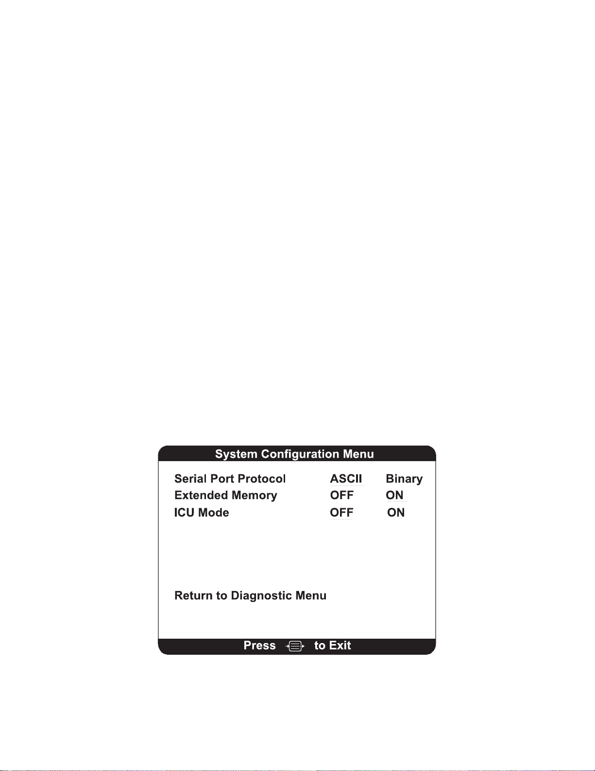
SECTION 7 DIAGNOSTICS AND TROUBLESHOOTING
______________________________________________________________________
7.1.4 Clear Data
This option clears all data from the system memory and starts a new case.
1. Press [MENU/EXIT] to access the Setup Menu.
2. Highlight Clear Data, using the [↑] or [↓] arrows.
3. Press [SELECT]. The system will respond with the message; “Clear Data Memory?”
4. Press [SELECT] to confirm, or press [MENU/EXIT] to cancel.
7.1.5 Diagnostic Codes
If you are experiencing problems with the A-2000 monitor, you may wish to turn the Diagnostic
Codes ON so that numerical diagnostic values will be displayed in the Message Region of the
screen. To do so, press [SELECT] when “Diagnostic Codes” is highlighted until “ON” appears in
reverse video. Then use the arrows to go to the next option, or press [MENU/EXIT] to exit.
7.1.6 Impedance Checking
The A-2000 continually checks impedance levels during a procedure by generating a 128 Hz
test signal. Occasionally this signal may interfere with other equipment. If this becomes a
problem, you may turn off the continuous impedance checking by pressing the [SELECT] key
until the “Impedance Checking –OFF” appears in reverse video. Then use the arrows to go to
the next option, or press [MENU/EXIT] to exit. Impedance levels will still be tested at startup,
but once they pass, they will not be tested again until a new case is begun.
Note:
Turning off continuous impedance checking will not be saved by
the “Save Current Settings” feature. The next time the monitor is
powered on, the monitor will re-enable continuous impedance
checking.
7.1.7 System Configuration Menu
Figure 27 The System Configuration Menu
7-3
Page 82

SECTION 7 DIAGNOSTICS AND TROUBLESHOOTING
______________________________________________________________________
Serial Port Protocol
Data may be transmitted from the serial port in two formats, ASCII and BINARY, depending
upon which option is selected. To select an option, use the down arrow when the Diagnostic
Menu is displayed until Serial Port Protocol is highlighted. Press [SELECT] until the desired
protocol appears in reverse video. Then use the arrows to go to the next option, or press
[MENU/EXIT] to exit. If a user is interested in acquiring data from the serial port, consult with an
Aspect representative and request the Aspect A-2000 Serial Port Specification (P/N 070-0017).
See back cover for contact information.
Extended Memory
The extended memory feature records and stores into memory BIS, EMG, SR, SQI, and
Burst/Min values at one-minute intervals for a period of up to 409 hours of active monitoring.
These values are accessible to the user via the BIS Log display. This information will remain in
memory (until overwritten) and can also be retrieved with the assistance of qualified Aspect
personnel via the external serial port, subject to appropriate provider consents. The customer
retains rights to access this data and Aspect will not access the data without permission of the
customer. Occasionally, Aspect may seek such permission to evaluate performance of the A2000 monitor and to provide user feedback.
ICU Mode / Extend Mode
When the ICU mode is set to ON, the BIS smoothing rate is set to 30 seconds, Alarm Suspend
is set to ON (so that alarms will only be silenced for 2 minutes), and the BIS Log interval is set
to 60 minutes. These individual parameters can be reset to other values independently. When
a BIS Extend sensor is attached, the system automatically switches to these same settings.
Return to Advanced Setup Menu
Press [SELECT] when this option is highlighted to return to the previous menu. To return to the
Main Screen, press [MENU/EXIT].
7-4
Page 83

SECTION 7 DIAGNOSTICS AND TROUBLESHOOTING
______________________________________________________________________
7.2 SYSTEM ERROR MESSAGE ALARMS
Equipment alarm messages, lead connection, and patient condition alarms (i.e., EEG isoelectric
condition) will appear in the message region of the display and an alarm sequence (two tones,
high/low, that sounds like “Uh-oh”) will sound when any of the following conditions occur: Digital
Signal Converter becomes disconnected, patient electrode leads come off, electrode impedance
check fails, or Digital Signal Converter has a power fault. Error messages and the
corresponding operator action required for these and other error conditions are listed below:
A-2000 Error Messages and Operator Action
E01 Message:
Operator Action:
E02 Message:
Operator Action:
E03 Message:
Operator Action:
E04, E05, E06, E07,
E08 Message:
Operator Action:
E09 Message:
Operator Action:
E10 Message:
Operator Action:
E11 Message:
Operator Action:
DSC Not Connected
Check that the blue cable from the DSC is connected to the
front panel of the monitor. If connected, and the DSC doesn’t
work, the DSC or monitor may require service.
DSC Overcurrent
The run-time diagnostics tries up to three times to clear this
error condition. If it doesn’t work, the DSC or monitor may
require service.
DSC Power Regulation
The run-time diagnostics checks three times for this error
condition. This indicates that the DSC may require service.
DSC Error
The DSC is not communicating or operating properly. This
may occur during the use of electrocautery devices. If the
message persists, the monitor or DSC may require service.
DSC Shut Down
Too many fatal errors (overcurrent, voltage regulation) have
occurred with this DSC and the monitor has stopped trying to
get it to work. Turn the monitor off, then on to try again. If
this problem persists, the DSC and/or monitor require
service.
Illegal DSC Type
An unrecognized DSC has been connected to the monitor.
Connect correct DSC. If error persists, the DSC and/or the
monitor may require service.
DSC Failed Self-Test
The DSC has failed either the noise test or gain test
performed at startup. The DSC and/or the monitor may
require service.
7-5
Page 84

SECTION 7 DIAGNOSTICS AND TROUBLESHOOTING
______________________________________________________________________
E12 Message:
Operator Action:
E13, E15 Message:
Operator Action:
E14 Message:
Operator Action:
E15 (See E13)
E16 Message:
Operator Action:
E17, E19 – E24
Message:
Operator Action:
E18 Message:
Operator Action:
E19 – E24 (see E17)
E25 Message:
Operator Action:
E26 Message:
Operator Action:
E27 Message:
Operator Action:
Illegal Sensor Type
An unrecognized Patient Interface Cable/Sensor has been
connected to the DSC. Make sure that the PIC connector is
clean and dry. (See Section 6.1). The PIC or Sensor may be
defective. Replace the PIC/Sensor.
Re-prep Sensor
The sensor has an impedance that is too high. Check the
cable connections and correct as necessary. If the message
persists, check the impedance of the sensor. Re-prep or
replace sensor as necessary.
Sensor Not Connected
Sensor or Patient Interface Cable is not connected. Patient
Interface Cable or Sensor may be defective. Replace PIC or
Sensor. If problem persists, DSC may require service.
Replace DSC.
Re-prep Sensor
Last Sensor Check Failed
The operator aborted the last “Sensor Check” operation while
the test was failing. Check connections, re-prep, or replace
Sensor.
BIS Engine Comm. Error
A communications error has been detected between the BIS
Engine and the Host processor. If the error persists, the
monitor requires service.
BIS Engine Not Functional
If the error persists, the monitor requires service.
BIS Engine Comm. Error
Left side SQI Bad
(2-channel monitoring only)
Right side SQI Bad
(2-channel monitoring only)
SQI Below 50%
The Signal Quality Index is poor. Note: the numeric display
changes from a solid to an outlined number. Check
Sensor/leads. May occur as a result of artifact such as those
generated from motion or eyeblinks
7-6
Page 85

SECTION 7 DIAGNOSTICS AND TROUBLESHOOTING
______________________________________________________________________
E28 Message:
Operator Action:
E29 Message:
Operator Action:
E30 Message:
Operator Action:
E31 Message:
Operator Action:
E32 Message:
Operator Action:
E33 Message:
Operator Action:
E34 Message:
Operator Action:
E35-E39, E43, E44,
E48-E65, E69-E73, E75,
E78-80, E87- E89, E110
Message:
Operator Action:
E40 Message:
Operator Action:
E41 Message:
Operator Action:
E42 Message:
Operator Action:
E43, E44 (See E35)
SQI Too Low For BIS
The Signal Quality Index is unacceptable therefore the Trend
variable cannot be calculated. Check Sensor. This may
occur as a result of artifact such as those generated from
motion or eyeblinks.
BIS < Low Alarm Limit
BIS > High Alarm Limit
Isoelectric EEG Detected
No discernible EEG activity is detected for several minutes;
SR = 100. Check the patient. Check the leads for proper
connection.
Review Data Lost
The contents of the data memory were lost and have been
re-initialized. If the error persists, the monitor requires
service.
Operating on Battery Backup
The AC power has been lost and the monitor is running on
the battery. The battery keeps the monitor operating for
approximately 20 minutes.
Battery Power Low
There are only a few minutes of battery life left. Restore AC
power to avoid automatic shutdown.
Software Error
The monitor requires service.
Setup Memory Write Error
Can’t save Setup data to non-volatile memory. Monitor
requires service.
Real-Time Clock Write Error
Can’t save time/date or data to non-volatile Real-Time Clock.
Monitor requires service.
Can’t Save Setup
This message should only appear when running on battery
power, the battery is low, and the user attempts to save setup
data. Restore AC power or save Setup data later.
Software Error
7-7
Page 86

SECTION 7 DIAGNOSTICS AND TROUBLESHOOTING
______________________________________________________________________
E45 Message:
Operator Action:
E46 Message:
Operator Action:
E47, E74, E81
Message:
Operator Action:
E48 – E65 (See E35)
E66 Message:
Operator Action:
E67, E82, E85
Message:
Operator Action:
E68 (not used)
E69 – E73 (See E35)
E74 (See E47)
E75 (See E35)
E76 Message:
Operator Action:
E77 Message:
Operator Action:
E78 – E80 (See E35)
E81 (See E47)
E82 (See E67)
No Updates From BIS Engine
No processed data from BIS Engine in the last 10 seconds. If
error persists, monitor may require service.
BIS Engine Not Responding
BIS Engine is not performing commands within the allowed
time limits. If error persists, monitor may require service.
Data Memory Write Error
Problem writing data to non-volatile memory. Monitor
requires service, but should continue to operate properly
(data memory storage time will be reduced).
Software Error
Printer out of Paper
Check the printer. Make sure that it has paper. If the error
persists, the printer requires service.
Printer Error
This indicates a printer hardware error. If the error persists,
the printer requires service.
Software Error
Data Memory Write Error
Software Error
Illegal Sensor for Demo
A demo device is attached to the serial port, but the sensor
connected through the DSC is not a valid demo sensor.
Simulator Connected
No action required. This message indicates that a demo
device is attached to the serial port of the A-2000 and the
A-2000 is not necessarily processing patient information
Software Error
Data Memory Write Error
Printer Error
7-8
Page 87

SECTION 7 DIAGNOSTICS AND TROUBLESHOOTING
______________________________________________________________________
E83 Message:
Operator Action:
E84 Message:
Operator Action:
E85 (See E67)
E86 Message:
Operator Action:
E87- E89 (See E35)
E90 Message:
Operator Action:
E91 Message:
Operator Action:
E92 (not used)
E93 Message:
Operator Action:
E94 Message:
Operator Action:
E95-E108 Message:
Operator Action:
E109 Message:
Operator Action:
E110 (See E35)
Printer Head is Up
The print head on the printer has been lifted. Return it to the
closed position. If the error persists, the printer requires
service.
Printer Disconnected
The printer is no longer connected to the A-2000. Check the
connection. If the error persists, the printer requires service.
Printer Error
Printing Disabled
The A-2000 is running on battery backup. When power is
restored to the A-2000, printing will again be available.
Software Error
Printer Connected
The printer has been successfully connected to the A-2000.
Event Marking Disabled
The ability to mark an event has been temporarily disabled. It
will be re-enabled when event data extraction has been
completed (less than 10 minutes).
Sensor Ground Fault
Disconnect and examine sensor; replace sensor if necessary.
If problem continues, connect new DSC, restart monitor.
Sensor Overcurrent
Disconnect and examine sensor; replace sensor if necessary.
Invalid Sensor
Replace sensor if necessary. The sensor is unusable for one
of the following reasons:
E95 – The sensor has been connected too many times
E96-E102, E107 – The sensor contains invalid information
E103-E106, E108 – The sensor information could not be
read.
Sensor used > 24 hours
The sensor has been in place for more than 24 hours.
Disconnect and replace sensor.
Software Error
7-9
Page 88

SECTION 7 DIAGNOSTICS AND TROUBLESHOOTING
______________________________________________________________________
7.3 WHAT TO DO IF THE A-2000 REQUIRES SERVICE
Contact your local distributor to determine where servicing will occur. If it becomes necessary
to return a unit directly to Aspect Medical Systems, follow the procedure below:
• Obtain return authorization. Contact Aspect’s Technical Service Department to obtain a
returned materials authorization (RMA) number. (The Technical Service phone number
is printed on the back cover of this manual.) The RMA number should appear on the
outside of the shipping container. Please provide the model number, serial number, and
a brief description of the reason for return.
• Use the original shipping container, if available, or equivalent packaging to protect the
product. Seal the package with plastic shipping tape rather than masking tape. Mark
shipping or storage container FRAGILE.
• If the repair or replacement is covered by the warranty, Aspect will bear the costs of
shipping the repaired or replacement product back to the user. All other shipping costs
shall be paid by the user.
7-10
Page 89

SECTION 8 SPECIFICATIONS, WARRANTY AND
SOFTWARE LICENSE AGREEMENT
______________________________________________________________________
SECTION 8
8 SPECIFICATIONS, WARRANTY AND SOFTWARE LICENSE
AGREEMENT
__________________________________________________________
8.1 SPECIFICATIONS
This section lists specifications for the Aspect A-2000 BIS Monitor.
General Specifications:
• Product Description:
• Monitor Weight:
• Monitor Dimensions:
• Digital Signal Converter:
Weight:
Dimensions:
Cable Length:
• Display Size:
• Digital Output:
• Power Requirements:
• Electrical Safety:
• Battery Backup:
• Software Updates:
• Processors:
BIS (Bispectral Index) monitor for display of
processed data and real-time EEG waveforms
3.1 lbs (1.4 kg)
7.0 in wide x 6.8 in high x 4.0 in deep
(17.5 cm x 16.9 cm x 10 cm)
10.0 oz (0.284 kg) including integral cable
2.6 in wide x 1.00 in high x 4.25 in deep
(6.6 cm x 2.5 cm x 10.8 cm)
12 ft (3.7 m) Integral DSC Cable
4 ½ ft (1.4 m) from DSC to sensor connector
3.4 in high x 4.5 in wide (8.5 cm x 11.25 cm)
RS232 serial port, printer port
100-240 VAC, 50-60 Hz, 1 ampere max.
Conforms to: UL 2601, CSA 22.2 No. 601-1 and
IEC 601-1
20 minutes at full operation
Recharge Time: 4 hours
User-via RS-232 serial port
Texas Instruments TMS 320C32 (50 MHz), Sharp
LH77790 Risc (25 MHz)
8-1
Page 90

SECTION 8 SPECIFICATIONS, WARRANTY AND
SOFTWARE LICENSE AGREEMENT
EEG Specifications:
• Epoch Duration:
• Artifact Rejection:
• EEG Scales:
• EEG Sweep Speeds:
• Computed Parameters:
• User-defined Displays:
• Update Rate:
• Event Markers:
• Alarms:
• Filters:
• Mode:
Digital Signal Converter Specifications:
• Analog to Digital Converter:
• Sampling Rate:
• Resolution:
• Input Impedance:
• Noise: < 0.3 μV RMS (2.0 μV peak-to-peak);
• Common Mode Rejection:
(Isolation mode)
• Bandwidth:
2 seconds
Automatic
25 μV/div (+/- 1 mV Full Scale)
Display Type – EEG: 5, 10, 25, 50 or 100 μV/div
25 mm/sec
Display Type – EEG: 15, 25, or 30 mm/sec
Bispectral Index, 95% Spectral Edge Frequency,
Suppression Ratio, EMG, and Signal Quality Index
TREND, DSA, the BIS Log, and real-time EEG
waveforms
1 second for BIS Index, 10 seconds for Trend/DSA
User selected
Auditory and visual, user adjustable limits
ON (2 – 70 Hz with notch) or OFF (.25 – 100 Hz)
Sensor automatically selects mode.
Noise-shaped sigma-delta
16,384 samples/second
16 Bits at 256 samples/second
50 Mohms minimum
0.25 Hz to 50 Hz
110 dB at 50/60 Hz to earth
ground
DSC – 2: 0.16 – 800 Hz
DSC – XP: 0.16 – 450 Hz
8-2
Page 91

SECTION 8 SPECIFICATIONS, WARRANTY AND
SOFTWARE LICENSE AGREEMENT
Type of Protection against Electric Shock of the System:
Class 1: Equipment in which protection against electric shock does not rely on basic
insulation only, but which includes an additional safety precaution. Means are provided
for the connection of the equipment to the protective earth conductor in the fixed wiring
of the installation in such a way that accessible metal parts cannot become live in the
event of a failure of the basic insulation.
Degree of Protection against Electric Shock of the System:
Type BF: Equipment providing a degree of protection against electric shock regarding
allowable leakage currents and reliability of the protective earth ground connection with
an F-type applied part. An F-type applied part is isolated from all other parts of the
equipment to such a degree that the patient leakage current allowable in single fault
condition is not exceeded when a voltage equal to 1.1 times the highest rated AC supply
voltage is applied between the applied part and earth.
Degree of Protection against effects of Cardiac Defibrillation:
The A-2000 system provides protection for the operator and patient during cardiac
defibrillation.
Degree of Protection against the Ingress of Water:
Monitor degree of protection rating: IPX2 (ingress of water vertically dripping)
DSC degree of protection rating: IPX4 (splash proof)
Mode of Operation of the System:
Continuous: Operation under normal load for a normal period without exceeding the
specified limits of temperature.
Classification:
MEDICAL ELECTRONIC EQUIPMENT
CLASSIFIED BY UNDERWRITERS LABORATORIES INC.®
WITH RESPECT TO ELECTRIC SHOCK, FIRE AND MECHANICAL HAZARDS ONLY
IN ACCORDANCE WITH
UL 2601-1, IEC601-2-26
CAN/CSA C22.2 NO. 601.1, CAN/CSA 601.2.26
42SA
8-3
Page 92

SECTION 8 SPECIFICATIONS, WARRANTY AND
SOFTWARE LICENSE AGREEMENT
8.2 WARRANTY
Aspect warrants to the initial Purchaser that the A-2000 BIS monitor and the Digital
Signal Converter (“Warranted Product”) will be free from defects in workmanship or
materials, when given normal, proper, and intended usage for a period of one year
(“Warranty Period”) from the date of its initial shipment to Purchaser. Excluded from this
warranty are expendable components and supply items such as, but not limited to,
electrodes, cables, and prep solutions. Aspect’s obligations under this warranty are to
repair or replace any Warranted Product (or part thereof) that Aspect reasonably
determines to be covered by this warranty and to be defective in workmanship or
materials provided that the Purchaser has given notice of such warranty claim within the
Warranty Period and the Warranted Product is returned to the factory with freight
prepaid. Repair or replacement of Products under this warranty does not extend the
Warranty Period.
To request repair or replacement under this warranty, Purchaser should contact Aspect
directly (see contact information on the back cover of this manual). Aspect will
authorize Purchaser to return the Warranted Product (or part thereof) to Aspect. Aspect
shall determine whether to repair or replace Products and parts covered by this warranty
and all Products or parts replaced shall become Aspect’s property. In the course of
warranty service, Aspect may but shall not be required to make engineering
improvements to the Warranted Product or part thereof. If Aspect reasonably
determines that a repair or replacement is covered by the warranty, Aspect shall bear
the costs of shipping the repaired or replacement Product to Purchaser. All other
shipping costs shall be paid by Purchaser. Risk of loss or damage during shipments
under this warranty shall be borne by the party shipping the Product. Products shipped
by Purchaser under this warranty shall be packaged in the original shipping container or
equivalent packaging to protect the Product. If Purchaser ships a Product to Aspect in
unsuitable packaging, any physical damage present in the Product on receipt by Aspect
(and not previously reported) will be presumed to have occurred in transit and will be the
responsibility of Purchaser.
This warranty does not extend to any Warranted Products or part thereof: that have
been subject to misuse, neglect, or accident; that have been damaged by causes
external to the Warranted Product, including but not limited to failure of or faulty
electrical power; that have been used in violation of Aspect’s instructions; that have been
affixed to any nonstandard accessory attachment; on which the serial number has been
removed or made illegible; that have been modified by anyone other than Aspect; or that
have been disassembled, serviced, or reassembled by anyone other than Aspect, unless
authorized by Aspect. Aspect shall have no obligation to make repairs, replacements, or
corrections which result, in whole or in part, from normal wear and tear. Aspect makes
no warranty (a) with respect to any products that are not Warranted Products, (b) with
respect to any products purchased from a person other than Aspect or an Aspectauthorized distributor or (c) with respect to any product sold under a brand name other
than Aspect Medical Systems, Inc.
8-4
Page 93

SECTION 8 SPECIFICATIONS, WARRANTY AND
SOFTWARE LICENSE AGREEMENT
THIS WARRANTY IS THE SOLE AND EXCLUSIVE WARRANTY FOR ASPECT’S
PRODUCTS, EXTENDS ONLY TO THE PURCHASER, AND IS EXPRESSLY IN LIEU
OF ANY OTHER EXPRESS OR IMPLIED WARRANTIES INCLUDING WITHOUT
LIMITATION ANY WARRANTY AS TO MERCHANTABILITY OR FITNESS FOR A
PARTICULAR PURPOSE. ASPECT’S MAXIMUM LIABILITY ARISING OUT OF THE
SALE OF THE PRODUCTS OR THEIR USE, WHETHER BASED ON WARRANTY,
CONTRACT, TORT, OR OTHERWISE, SHALL NOT EXCEED THE ACTUAL
PAYMENTS RECEIVED BY ASPECT IN CONNECTION THEREWITH. ASPECT
SHALL NOT BE LIABLE FOR ANY INCIDENTAL, SPECIAL, OR CONSEQUENTIAL
LOSS, DAMAGE OR EXPENSE (INCLUDING WITHOUT LIMITATION LOST PROFITS)
DIRECTLY OR INDIRECTLY ARISING FROM THE SALE, INABILITY TO SELL, USE
OR LOSS OF USE OF ANY PRODUCT. EXCEPT AS SET FORTH HEREIN, ALL
PRODUCTS ARE SUPPLIED “AS IS” WITHOUT WARRANTY OF ANY KIND, EITHER
EXPRESS OR IMPLIED.
8-5
Page 94

SECTION 8 SPECIFICATIONS, WARRANTY AND
SOFTWARE LICENSE AGREEMENT
8.3 SOFTWARE LICENSE AGREEMENT
The computer software (“Licensed Software”) loaded on the A-2000 BIS Monitor
(“System”) is licensed, not sold, to you for use only under the terms of this license.
Aspect Medical Systems, Inc. (“Aspect”) reserves any rights not expressly granted to
you. You own the System, but Aspect retains all ownership rights and title to the
Licensed Software itself.
1. LICENSE: You are hereby granted the non-exclusive right to use the Licensed
Software solely with the specific System on which the Licensed Software was
provided to you.
2. RESTRICTIONS: You shall not transfer the Licensed Software in any manner from
the System to any other computer or system without the prior written consent of
Aspect. You shall not distribute copies of the Licensed Software or its related
documentation to others. You shall not modify or translate the Licensed Software or
its related documentation without the prior written consent of Aspect. The Licensed
Software contains trade secrets and to protect them you may not decompile, reverse
engineer, disassemble, or otherwise reduce the Licensed Software to a humanperceivable form. If you transfer the System, you have the right to transfer the
Licensed Software provided that the transferee agrees to be bound by the terms and
conditions of this License Agreement.
3. TERMINATION: This License remains effective until terminated. This License will
terminate automatically without notice from Aspect if you fail to comply with any term
or provision of this License. Upon termination of this License, you may not make any
further use of the Licensed Software.
4. LIMITED WARRANTY: THE LICENSED SOFTWARE IS PROVIDED “AS IS”
WITHOUT WARRANTY OF ANY KIND, EITHER EXPRESS OR IMPLIED,
INCLUDING WITHOUT LIMITATION ANY WARRANTY WITH RESPECT TO ITS
MERCHANTABILITY OR ITS FITNESS FOR ANY PARTICULAR PURPOSE.
ASPECT DOES NOT WARRANT THAT THE FUNCTIONS CONTAINED IN THE
LICENSED SOFTWARE WILL MEET YOUR REQUIREMENTS OR THAT THE
OPERATION OF THE LICENSED SOFTWARE WILL BE UNINTERRUPTED OR
ERROR FREE OR THAT SUCH ERRORS IN THE LICENSED SOFTWARE WILL
BE CORRECTED.
5. LIMITATION OF REMEDIES AND DAMAGES: ASPECT’S ENTIRE LIABILITY TO
YOU FOR ACTUAL DAMAGES FOR ANY CAUSE WHATSOEVER, AND
REGARDLESS OF THE FORM OF THE ACTION, AND YOUR EXCLUSIVE
REMEDY SHALL BE LIMITED TO THE MONEY PAID FOR THE SYSTEM, WHICH
INCLUDED THE LICENSED SOFTWARE.
8-6
Page 95

SECTION 8 SPECIFICATIONS, WARRANTY AND
SOFTWARE LICENSE AGREEMENT
IN NO EVENT SHALL ASPECT BE LIABLE TO YOU ( I ) FOR ANY INCIDENTAL,
CONSEQUENTIAL, OR INDIRECT DAMAGES (INCLUDING DAMAGES FOR LOSS
OF BUSINESS PROFITS, BUSINESS INTERRUPTION, LOSS OF BUSINESS
INFORMATION, AND THE LIKE) ARISING OUT OF THE USE OF OR INABILITY
TO USE ANY LICENSED SOFTWARE EVEN IF ASPECT OR ANY AUTHORIZED
ASPECT REPRESENTATIVE HAS BEEN ADVISED OF THE POSSIBILITY OF
SUCH DAMAGES, OR (ii) FOR ANY CLAIM BY ANY OTHER PARTY.
6. GENERAL: This License Agreement will be construed under the laws of the
Commonwealth of Massachusetts. If any provision of this License Agreement shall
be held by a court of competent jurisdiction to be contrary to law, that provision will
be enforced to the maximum extent permissible, and the remaining provisions of this
Agreement will remain in full force and effect.
Should you have any questions concerning this License Agreement, you may contact
Aspect by writing to Aspect Medical Systems, Technical Service. (See back cover for
contact information.)
THIS LICENSE AGREEMENT IS THE COMPLETE AND EXCLUSIVE STATEMENT OF
THE AGREEMENT BETWEEN YOU AND ASPECT AND SUPERSEDES ANY
PROPOSAL OR PRIOR AGREEMENT, ORAL OR WRITTEN, AND ANY OTHER
COMMUNICATIONS BETWEEN YOU AND ASPECT RELATING TO THE SUBJECT
MATTER OF THIS AGREEMENT.
8-7
Page 96

SECTION 8 SPECIFICATIONS, WARRANTY AND
SOFTWARE LICENSE AGREEMENT
8-8
Page 97

SECTION 9 APPENDIX
______________________________________________________________________
SECTION 9
9 APPENDIX
9.1 APPENDIX I – PROCESSED EEG VARIABLES
Variable Name Description Range
Bispectral Index
(BIS)
Signal Quality
Index (SQI)
EMG The absolute power in the 70-110 Hz range.
Suppression
Ratio (SR)
Burst Count The number of EEG bursts per minute, where
Spectral Edge
Frequency (SEF)
The output from a multivariate discriminate
analysis that quantifies the overall bispectral
properties (frequency, power, and phase)
throughout the entire frequency range.
A measure of the signal quality for the EEG
channel source(s) that is calculated based on
impedance data, artifact, and other variables.
Not affected by Suppression Ratio.
The power value is reported in dB with respect
to 0.0001μV2. All the artifact detection is
turned off for this variable.
The percentage of epochs in the past 63
seconds in which the EEG signal is
considered suppressed.
a “burst” is defined as a short period of EEG
activity preceded and followed by periods of
inactivity (suppression).
The frequency at which 95% of the total power
lies below it and 5% lies above it.
0.0 – 100.0
0.0 – 100.0
30 – 80 dB Trend
30 – 55 dB Bar
Graph
0.0 – 100.0 %
0 – 20
0.5 - 30.00 Hz
9-1
Page 98
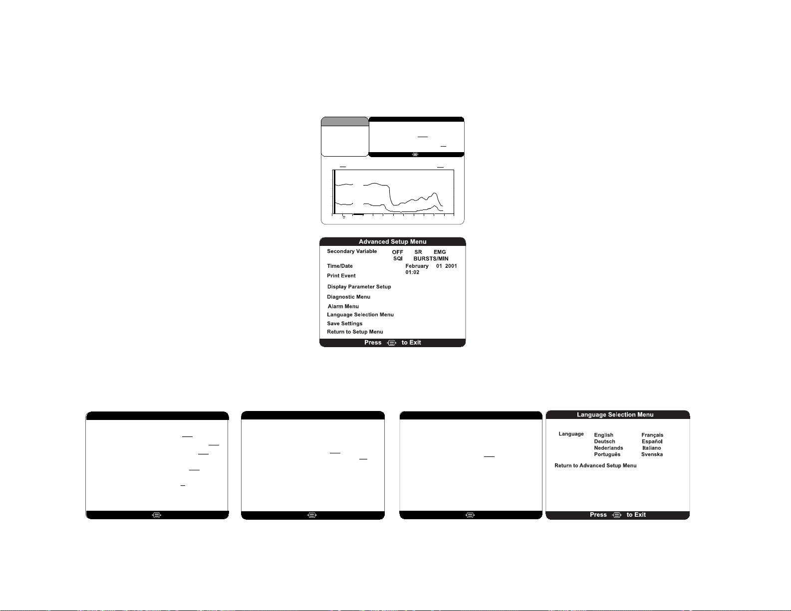
SECTION 9 APPENDIX
____________________________________________________________________________________________________
9.2 A-2000 MENU MAP
BIS
4242
BIS EMG09 Feb 2000 12:55:02
100
80
60
40
20
0
12:10 12:20 12:30 12:40 12:50 13:0012:00
Setup Menu
Event
Sensor Check
Display Type Trend DSA
BIS Smoothing Rate (secs.) 15 30
Advanced Setup
Press
BIS Log EEG
to Exit
CASE:aG2c
80
70
60
50
40
30
Display Parameter Setup
Dual EEG Display OFF ON
Filters OFF ON
EEG Sweep Speed
(mm/sec)
EEG Amplitude
(uv/div)
BIS Log Interval
(minutes)
Return to Advanced Setup Menu
5 10 25 50 100
to ExitPress
⇓
⇙ ⇓ ⇓ ⇘
Diagnostic Menu
. . . . . . . . . . 3.00
. . . . . . . . . . . . 3.00
. . . . . . 1.13
. . . . . . . . . . . 1.06
. . . . . . . . 567891
Serial Number
. . . . . . . . C002033
BIS Usage
. . . . . . . . . . . . . . . 125
DSC FPGA . . . . . . . . . . . . . 2.0.1.6
DSC Type . . . . . . . . . . . . . . . . . .8
PIC/Sensor Type . . . . . . . . . . . . .4
to ExitPress
High Alarm Limit OFF
Low Alarm Limit OFF
Alarm Suspend ON OFF
Return to Advanced Setup Menu
15 25 30
1 5 15 60
DSC Self Test
Display Self Test
Sensor Data Display
Clear Data
Diagnostic Codes ONOFF
Impedance Checking OFF ON
System Configuration Menu
Return to Advanced Setup Menu
System Revision
Host Revision
BIS Engine Revision
FPGA Revision
Run Time . . . . .
9-2
Alarm Menu
to ExitPress
Page 99
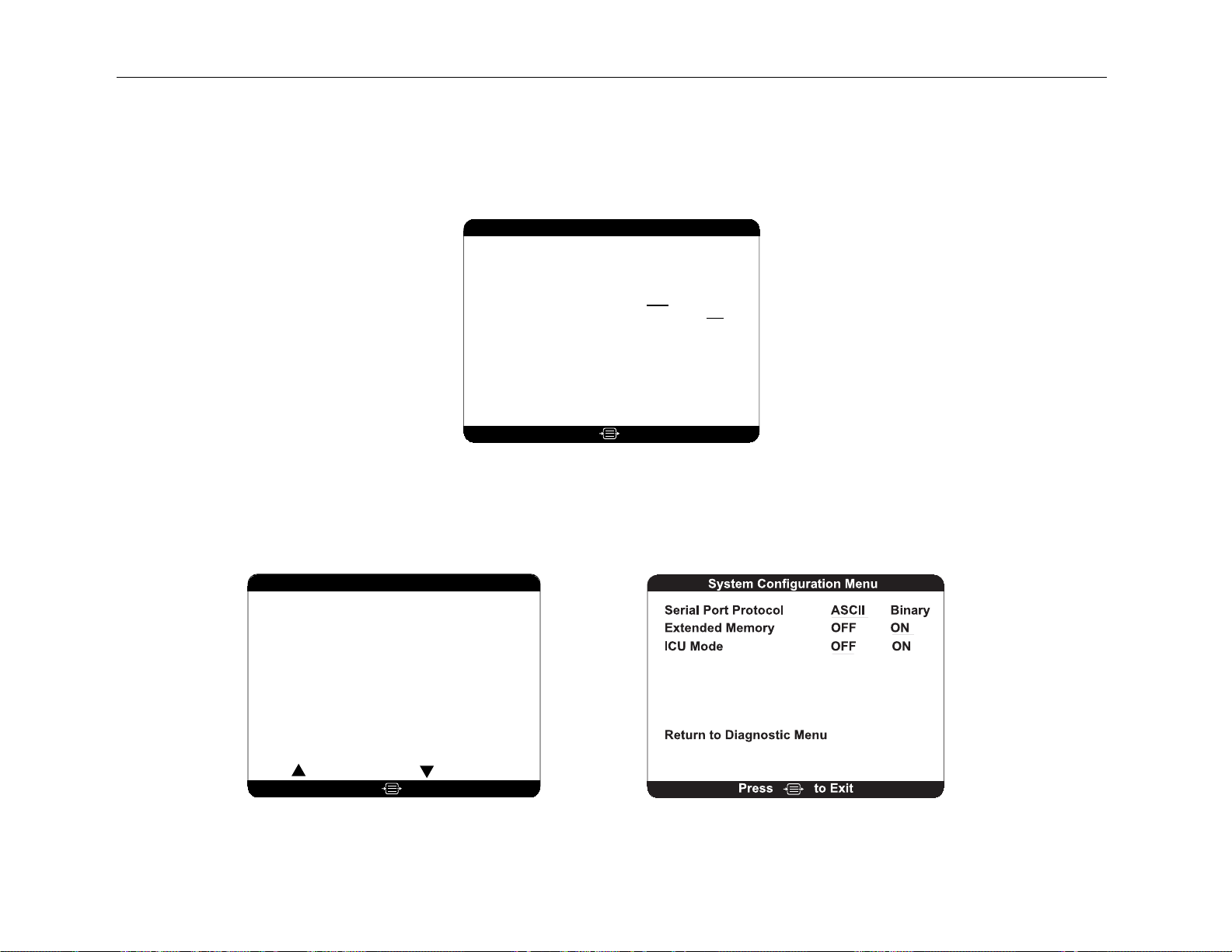
SECTION 9 APPENDIX
Diagnostic Menu
DSC Self Test
Display Self Test
Sensor Data Display
Clear Data
Diagnostic Codes ONOFF
Impedance Checking OFF ON
System Configuration Menu
Return to Advanced Setup Menu
System Revision
Host Revision
BIS Engine Revision
FPGA Revision
Run Time . . . . .
. . . . . . . . . . 3.00
. . . . . . . . . . . . 3.00
. . . . . . 1.13
. . . . . . . . . . . 1.06
. . . . . . . . 567891
Serial Number
BIS Usage
DSC FPGA . . . . . . . . . . . . . 2.0.1.6
DSC Type . . . . . . . . . . . . . . . . . .8
PIC/Sensor Type . . . . . . . . . . . . .4
. . . . . . . . C002033
. . . . . . . . . . . . . . . 125
to ExitPress
⇙ ⇘
Sensor Data Display
Lot Code . . . . . . . .
Serial Number . . . . . . .
Sensor Type . . . . . . . . . . . XP
Use By . . . . . . . . . . Jan 2000
Used (> 5 minutes) . . . . .
Connection Count . . . . . . .
02 Jun 1999 12:54:55 003
02 Jun 1999 13:01:02 002
Previous Sensor Next Sensor
Connections
0220003f
12345
YES
2
to ExitPress
9-3
Page 100

SECTION 9 APPENDIX
9-4
 Loading...