

Page 1
BIS VISTA™ Monitoring System
OPERATING MANUAL
Rx only
Aspect Medical Systems, Inc. Aspect Medical Systems International B.V.
One Upland Road Rijnzathe 7d2
Norwood, MA 02062 3454 PV De Meern
U.S.A. The Netherlands 0123
(Tel) 617-559-7000 Tel: +31.30.662.9140
(Tel) 888-BIS INDE(X) (U.S. only) Fax: +31.30.662.9150
(Fax) 617-559-7400 amsint@aspectms.com
bis_info@aspectms.com
www.aspectmedical.com
070-0069 3.00
EC REP
Page 2

Page 3

BIS VISTA™ Monitoring System
OPERATING MANUAL
© Copyright, 2008, Aspect Medical Systems, Inc. All rights reserved. Copying or other
reproduction of this document is prohibited without prior written consent of Aspect
Medical Systems, Inc.
BIS VISTA is a trademark of Aspect Medical Systems, Inc.
Aspect, Bispectral Index, BIS, the BIS logo, BISx, the BISx logo and Zipprep are trademarks
of Aspect Medical Systems, Inc. and are registered in the U.S.A., E.U. and other countries.
Page 4

Page 5

TABLE OF CONTENTS
ABOUT THIS MANUAL........................................................................................ i
INTRODUCING THE BIS VISTA MONITORING SYSTEM............................ ii
1 SAFETY PRECAUTIONS........................................................................... 1-1
1.1 Warnings....................................................................................................................... 1-1
1.2 Cautions........................................................................................................................1-3
1.3 Key to Symbols ............................................................................................................ 1-6
2 INSTALLATION AND PREPARATION FOR USE ................................ 2-1
2.1 BIS VISTA Monitor Installation and Checkout ........................................................ 2-1
2.2 Environment................................................................................................................. 2-2
2.2.1 Shipping and Storage Environment....................................................................................................... 2-2
2.2.2 Operating Environment .......................................................................................................................... 2-2
2.2.3 Power Requirements and System Grounding.................................................................................... 2-3
2.2.4 Electromagnetic Compatibility Requirements.................................................................................... 2-3
2.2.5 Site Preparation: Mounting the Monitor ............................................................................................. 2-4
2.2.5.1 Mounting the Monitor using the Pole Clamp.......................................................................... 2-4
2.2.5.2 Optional Mounting Accessories................................................................................................. 2-5
2.3 The BIS VISTA Monitoring System – Equipment and Supplies ............................. 2-6
2.3.1 BIS VISTA Monitor .................................................................................................................................. 2-7
2.3.1.1 Front Panel...................................................................................................................................... 2-7
2.3.1.2 Touch Screen ................................................................................................................................. 2-7
2.3.1.3 ON/Standby button ...................................................................................................................... 2-7
2.3.1.4 Rear Panel....................................................................................................................................... 2-7
2.3.1.5 Integral Battery .............................................................................................................................. 2-9
2.3.2 BISx ........................................................................................................................................................... 2-10
2.3.3 Patient Interface Cable (PIC)............................................................................................................... 2-11
2.3.4 BIS Sensors .............................................................................................................................................. 2-11
2.4 Cable Connections..................................................................................................... 2-11
2.5 Start Procedure / Standby Mode ............................................................................. 2-12
2.5.1 Starting the Monitor for the First Time ............................................................................................ 2-12
2.5.2 Starting the Monitor from Standby Mode......................................................................................... 2-12
2.6 Initial Menu Settings.................................................................................................. 2-12
2.6.1 Language Selection ................................................................................................................................. 2-13
2.6.2 Date and Time ........................................................................................................................................ 2-13
2.6.3 View/Save Settings.................................................................................................................................. 2-13
Page 6

3 OPERATING THE BIS VISTA MONITORING SYSTEM....................... 3-1
3.1 Preparing for Operation ............................................................................................. 3-1
3.2 Sensor Check................................................................................................................ 3-3
3.3 BIS Trend Data Screen ............................................................................................... 3-6
3.3.1 BIS (Bispectral Index) Value ................................................................................................................... 3-6
3.3.2 Signal Quality Indicator ........................................................................................................................... 3-6
3.3.3 Electromyograph (EMG) Indicator ....................................................................................................... 3-7
3.3.4 EEG Waveform Display .......................................................................................................................... 3-7
3.3.5 Message Region ........................................................................................................................................ 3-7
3.3.6 BIS Trend Graph ...................................................................................................................................... 3-8
3.3.7 Additional Screen Information .............................................................................................................. 3-9
3.3.7.1 Battery Icon.................................................................................................................................... 3-9
3.3.7.2 USB Export Icon............................................................................................................................ 3-9
3.3.7.3 Print Icon....................................................................................................................................... 3-10
3.3.7.4 Extend Mode................................................................................................................................ 3-10
3.3.7.5 Suppression Ratio (SR) Number.............................................................................................. 3-10
3.3.7.6 Burst Count (Bursts/Minute).................................................................................................... 3-10
3.4 Main Screen Touch Keys........................................................................................... 3-11
3.4.1 Alarm Touch Keys ................................................................................................................................. 3-11
3.4.2 Menu, Home, Sensor Check and Review Touch Keys................................................................... 3-12
3.5 Menu Selections ......................................................................................................... 3-13
3.5.1 Target Range ........................................................................................................................................... 3-13
3.5.2 Secondary Variable ................................................................................................................................ 3-15
3.5.3 Chart Data............................................................................................................................................... 3-16
3.5.4 Alarm Volume......................................................................................................................................... 3-17
3.5.5 BIS/EEG Display Modes.........................................................................................................................3-18
3.5.6 View/Save Settings.................................................................................................................................. 3-18
3.5.7 Help........................................................................................................................................................... 3-19
3.5.8 Snapshot................................................................................................................................................... 3-20
3.5.9 Display Suppression Ratio (SR) ...........................................................................................................3-20
3.5.10 Monitor Mode ................................................................................................................................... 3-21
3.5.11 Export Data ....................................................................................................................................... 3-22
3.5.12 BIS Smoothing Rate.......................................................................................................................... 3-24
3.5.13 Print (Snapshot)................................................................................................................................. 3-25
3.5.14 Configuration Information.............................................................................................................. 3-26
3.5.15 EEG Channels.................................................................................................................................... 3-26
3.5.16 Date and Time................................................................................................................................... 3-27
3.5.17 Language ............................................................................................................................................. 3-28
3.5.18 Filters................................................................................................................................................... 3-28
3.5.19 Impedance Checking........................................................................................................................ 3-29
3.5.20 Maintenance Menu............................................................................................................................ 3-30
3.5.21 Demo Case ........................................................................................................................................ 3-30
3.5.22 Diagnostic Menu ............................................................................................................................... 3-30
3.6 Reviewing and Printing Stored Trend Data............................................................ 3-31
3.6.1 Review Mode Touch Keys ................................................................................................................... 3-31
3.6.2 Printing Stored Data.............................................................................................................................. 3-33
3.7 EEG Display ................................................................................................................ 3-34
Page 7

3.8 Ending a Case ............................................................................................................. 3-34
3.9 Data Transfer ............................................................................................................. 3-35
3.10 How the BIS VISTA Monitoring System Works.................................................... 3-36
3.10.1 Bispectral Index (BIS).......................................................................................................................3-37
3.10.2 Artifact Detection............................................................................................................................. 3-37
3.10.3 System Self-Checks........................................................................................................................... 3-37
3.10.4 Monitor Data Memory ....................................................................................................................3-38
3.10.5 BISx Data Memory ........................................................................................................................... 3-38
3.10.6 Battery Operation ............................................................................................................................ 3-39
4 QUICK REFERENCE GUIDE ..................................................................... 4-1
5 PREVENTIVE MAINTENANCE, CARE AND CLEANING.................... 5-1
5.1 Care and Cleaning ....................................................................................................... 5-1
5.2 Maintenance ................................................................................................................. 5-2
5.2.1 Replace the PIC (Patient Interface Cable) .......................................................................................... 5-2
5.2.2 Checking Cable Integrity ........................................................................................................................ 5-3
5.2.3 System Checkout ..................................................................................................................................... 5-3
5.2.4 Checking the Battery............................................................................................................................... 5-4
5.2.5 Replacing the Battery .............................................................................................................................. 5-4
5.2.6 Replacing the Power Supply................................................................................................................... 5-5
5.2.7 Checking Leakage Current..................................................................................................................... 5-6
5.3 Technical Documentation .......................................................................................... 5-7
5.4 Instrument Identification............................................................................................ 5-7
6 DIAGNOSTICS AND TROUBLESHOOTING ........................................ 6-1
6.1 Maintenance Menu....................................................................................................... 6-1
6.1.1 Display BISx Connection History ......................................................................................................... 6-1
6.1.2 Serial Protocol .......................................................................................................................................... 6-1
6.1.3 Software Update....................................................................................................................................... 6-2
6.1.4 Restore Default Settings for All Modes............................................................................................... 6-2
6.1.5 Calibrate Touch Screen .......................................................................................................................... 6-2
6.2 Diagnostic Menu .......................................................................................................... 6-3
6.2.1 Diagnostic Codes ..................................................................................................................................... 6-3
6.2.2 DSC Self Test............................................................................................................................................ 6-3
6.3 BIS VISTA System Messages and Corrective Actions ............................................ 6-4
6.4 Using the Reset button ............................................................................................. 6-11
6.5 What to do if the BIS VISTA Monitoring System Requires Service.................... 6-11
7 APPENDIX I: MENUS, PROCESSED VARIABLES AND GLOSSARY. 7-1
Page 8

7.1 Menu Map ..................................................................................................................... 7-1
7.2 Menu Listing ................................................................................................................. 7-2
7.3 Processed EEG Variables ............................................................................................ 7-4
7.4 Glossary......................................................................................................................... 7-5
8 APPENDIX II: SPECIFICATIONS, WARRANTY AND SOFTWARE
LICENSE AGREEMENT..................................................................................... 8-1
8.1 Specifications................................................................................................................ 8-1
8.2 Electromagnetic Compatibility Specifications ......................................................... 8-5
8.2.1 Accessories................................................................................................................................................ 8-5
8.2.2 IEC 60601-1-2:2001 Electromagnetic Compatibility Guidance...................................................... 8-6
8.3 Warranty .................................................................................................................... 8-11
8.4 Software License Agreement................................................................................... 8-13
Page 9

TABLE OF FIGURES
Figure 1 - Symbol Key (page 1 of 3) .............................................................................................1-6
Figure 2 - Pole Clamp...................................................................................................................... 2-4
Figure 3 - The BIS VISTA Monitoring System........................................................................... 2-6
Figure 4 - Rear Panel ....................................................................................................................... 2-8
Figure 5 - BISx and PIC................................................................................................................ 2-10
Figure 6 - Connecting the PIC....................................................................................................... 3-3
Figure 7 - Sensor Check Graphic Screen (Values not Shown).................................................. 3-4
Figure 8 - Sensor Check Graphic Screen with Values Shown................................................... 3-5
Figure 9 - Screen Features – BIS Trend Data Screen................................................................. 3-6
Figure 10 - BIS Trend Data Screen with Battery Icon, Target Range, SR, and Burst Count3-9
Figure 11 - Alarm Touch Keys ....................................................................................................3-11
Figure 12 - Menu, Home, Sensor Check and Review Mode Touch Keys............................. 3-12
Figure 13 - Target Range............................................................................................................... 3-13
Figure 14 - Secondary Variable .................................................................................................... 3-15
Figure 15 - Chart Data...................................................................................................................3-16
Figure 16 - Alarm Volume............................................................................................................3-17
Figure 17 - BIS/EEG Display Modes ........................................................................................ 3-18
Figure 18 - View/Save Settings.................................................................................................... 3-18
Figure 19 - Help ............................................................................................................................. 3-19
Figure 20 - Snapshot...................................................................................................................... 3-20
Figure 21 - Display SR................................................................................................................... 3-20
Figure 22 - Monitor Mode Settings ............................................................................................. 3-21
Figure 23 - Export Data................................................................................................................3-22
Figure 24 - Smoothing Rate.......................................................................................................... 3-24
Figure 25 - “Print” Touch Key ....................................................................................................3-25
Figure 26 - Configuration Information....................................................................................... 3-26
Figure 27 - EEG Channels ........................................................................................................... 3-26
Figure 28 - Date and Time............................................................................................................ 3-27
Figure 29 - Language Menu..........................................................................................................3-28
Figure 30 - Filters........................................................................................................................... 3-28
Figure 31 - Impedance Checking ON/OFF.............................................................................. 3-29
Figure 32 - Review Screen (Case Mode)..................................................................................... 3-31
Figure 33 - Review Screen (Cursor Mode)................................................................................. 3-32
Figure 34 - EEG Display .............................................................................................................. 3-34
Figure 35 - BIS Range Guidelines ............................................................................................... 3-36
Figure 36 - Replacing the Power Supply....................................................................................... 5-5
Figure 37 - Diagnostic Codes ON/OFF...................................................................................... 6-3
Figure 38 - BIS VISTA Menu Map ............................................................................................... 7-1
Page 10

ABOUT THIS MANUAL
This Operating Manual contains all of the information you need to set up and operate the
Aspect Medical Systems BIS VISTA™ Monitoring System. It also includes specific cleaning
and test procedures you may occasionally be required to perform. Although this manual is
intended for trained medical personnel, it does not assume prior knowledge or experience
with operator-programmable medical electronics devices.
Keep this Operating Manual with the BIS VISTA monitor for use by the operator. This
manual is also intended to be a service information manual for service technicians or
biomedical engineering personnel.
Before attempting to set up or use the BIS VISTA system, please familiarize yourself
with the safety information provided in this section.
i
Page 11

INTRODUCING THE BIS VISTA MONITORING SYSTEM
Introduction
The BIS VISTA Monitoring System is a user-configurable patient monitoring system
designed to monitor the hypnotic state of the brain based on acquisition and processing of
EEG signals. The BIS VISTA system processes raw EEG signals to produce a single
number, called the Bispectral Index™, or BIS, which correlates with the patient's level of
hypnosis.
The BIS VISTA monitor display consists of:
• The current BIS number
• Trend graphs of processed EEG parameters
• Raw EEG waveforms in real time
• Various signal quality indicators (EMG, SQI)
• Suppression Ratio (if requested by the user)
• Burst Count number (when a BIS Extend Sensor is in use)
• Alarm Indicator and Messages
The system performs self-tests to ensure that the monitor and its components are
functioning properly and that impedance levels of patient sensors are within acceptable
limits. Touch screen menus allow the user to change the data display and review stored data.
ii
Page 12

Important Information about Using BIS Monitoring
The BIS EEG VISTA Monitor System is intended for use under the direct supervision of a
licensed healthcare practitioner or by personnel trained in its proper use. The system, and all
its associated parameters, is intended for use on adult and pediatric patients within a hospital
or medical facility providing patient care to monitor the state of the brain by data acquisition
of EEG signals.
The BIS Index, one of the VISTA Monitor output parameters, may be used as an aid
in monitoring the effects of certain anesthetic agents; and its usage with certain
anesthetic agents may be associated with a reduction in primary anesthetic use and a
reduction in emergence and recovery time.
Use of the BIS Index for monitoring to help guide anesthetic administration may be
associated with the reduction of incidence of awareness with recall in adults during general
anesthesia and sedation.
BIS is a complex monitoring technology intended for use as an adjunct to clinical judgment
and training. Clinical judgment should always be used when interpreting BIS in conjunction
with other available clinical signs. Reliance on BIS alone for intraoperative anesthetic
management is not recommended. As with any monitored parameter, artifacts and poor
signal quality may lead to inappropriate BIS values. Potential artifacts may be caused by poor
skin contact (high impedance), muscle activity or rigidity, head and body motion, sustained
eye movements, improper sensor placement and unusual or excessive electrical interference.
BIS values should also be interpreted cautiously with certain anesthetic combinations, such
as those relying primarily on either ketamine or nitrous oxide/narcotics to produce
unconsciousness. Due to limited clinical experience in the following applications, BIS values
should be interpreted cautiously in patients with known neurological disorders and those
taking other psychoactive medications.
The BIS education site, www.biseducation.com, offers relevant information and published
articles on the clinical use of BIS. In addition, there is a “Monitoring Consciousness Using
the Bispectral Index during Anesthesia” Clinician’s Pocket Guide available on the website
and through your local Aspect Representative.
For more information, please contact Aspect Medical Systems at (800) 442-2051. If you
require additional information on the use of BIS, please contact Aspect Medical Systems
Clinical Support at 800-442-8655 or 617-559-7655 if calling from outside of the USA.
iii
Page 13

SECTION 1 SAFETY PRECAUTIONS
______________________________________________________________________
1 SAFETY PRECAUTIONS
INTRODUCTION
Caution:
Carefully read this entire manual before using the monitor in a clinical
setting.
WARNINGS, CAUTIONS, AND NOTES
The terms warning, caution, and note have specific meanings in this manual.
• A WARNING advises against certain actions or situations that could result in
personal injury or death.
• A CAUTION advises against actions or situations that could damage equipment,
produce inaccurate data, or invalidate a procedure, although personal injury is
unlikely.
• A NOTE provides useful information regarding a function or procedure.
KEY TO SYMBOLS
A key to the symbols that may appear on the BIS VISTA system appears at the end of this
section.
1.1 Warnings
EXPLOSION HAZARD: DO NOT USE THE BIS VISTA SYSTEM IN A
FLAMMABLE ATMOSPHERE OR WHERE CONCENTRATIONS OF
FLAMMABLE ANESTHETICS MAY OCCUR.
MONITOR IS NOT DESIGNED FOR USE IN MRI ENVIRONMENT.
USE ONLY THE POWER CORD SUPPLIED BY THE MANUFACTURER.
NEVER ADAPT THE PLUG FROM THE MONITOR TO FIT A NONSTANDARD OUTLET.
U.S.A. REQUIREMENT: FOR PROPER GROUNDING, THE POWER
RECEPTACLE MUST BE A THREE-WIRE GROUNDED OUTLET. A
HOSPITAL GRADE OUTLET IS REQUIRED. NEVER ADAPT THE THREEPRONG PLUG FROM THE MONITOR TO FIT A TWO-SLOT OUTLET. IF
THE OUTLET HAS ONLY TWO SLOTS, MAKE SURE THAT IT IS
REPLACED WITH A THREE-SLOT GROUNDED OUTLET BEFORE
ATTEMPTING TO OPERATE THE MONITOR.
1-1
Page 14

SECTION 1 SAFETY PRECAUTIONS
______________________________________________________________________
IF THE INTEGRITY OF THE EXTERNAL PROTECTIVE EARTH GROUND
IS IN DOUBT, THE BIS VISTA SYSTEM SHALL BE OPERATED FROM ITS
INTERNAL BATTERY POWER SOURCE ONLY.
BE SURE THE MONITOR IS MOUNTED SECURELY IN PLACE TO AVOID
PERSONAL OR PATIENT INJURY.
WHEN CONNECTING EXTERNAL EQUIPMENT (e.g., DATA CAPTURE
COMPUTER), THE SYSTEM LEAKAGE CURRENT MUST BE CHECKED
AND MUST BE LESS THAN THE IEC 60601-1-1 LIMIT.
THE USE OF ACCESSORY EQUIPMENT NOT COMPLYING WITH THE
EQUIVALENT SAFETY REQUIREMENTS OF THIS EQUIPMENT MAY
LEAD TO A REDUCED LEVEL OF SAFETY OF THE RESULTING SYSTEM.
CONSIDERATION RELATING TO THE CHOICE SHALL INCLUDE:
• USE OF THE ACCESSORY IN THE PATIENT VICINITY
• EVIDENCE THAT THE SAFETY CERTIFICATION OF THE
ACCESSORY HAS BEEN PERFORMED IN ACCORDANCE TO THE
APPROPRIATE IEC 60601-1 AND/OR IEC 60601-1-1 HARMONIZED
NATIONAL STANDARD.
DUE TO ELEVATED SURFACE TEMPERATURE, DO NOT PLACE BISx™ IN
PROLONGED DIRECT CONTACT WITH PATIENT’S SKIN, AS IT MAY
CAUSE DISCOMFORT.
THE CONDUCTIVE PARTS OF ELECTRODES OR SENSOR AND
CONNECTORS SHOULD NOT CONTACT OTHER CONDUCTIVE PARTS,
INCLUDING EARTH.
TO REDUCE THE HAZARD OF BURNS DURING USE OF HIGHFREQUENCY SURGICAL EQUIPMENT, THE SENSOR OR ELECTRODES
SHOULD NOT BE LOCATED BETWEEN THE SURGICAL SITE AND THE
ELECTRO-SURGICAL UNIT RETURN ELECTRODE.
TO REDUCE THE HAZARD OF BURNS DURING USE OF BRAINSTIMULATING DEVICES (e.g., TRANSCRANIAL ELECTRICAL MOTOR
EVOKED POTENTIAL), PLACE STIMULATING ELECTRODES AS FAR AS
POSSIBLE FROM THE BIS SENSOR AND MAKE CERTAIN THAT SENSOR IS
PLACED ACCORDING TO PACKAGE INSTRUCTIONS.
THE SENSOR MUST NOT BE LOCATED BETWEEN DEFIBRILLATOR
PADS WHEN A DEFIBRILLATOR IS USED ON A PATIENT CONNECTED
TO THE BIS VISTA SYSTEM.
TO MINIMIZE THE RISK OF PATIENT STRANGULATION, THE PATIENT
INTERFACE CABLE (PIC) MUST BE CAREFULLY PLACED AND SECURED.
1-2
Page 15

SECTION 1 SAFETY PRECAUTIONS
______________________________________________________________________
SHOCK HAZARD: DO NOT ATTEMPT TO DISCONNECT THE POWER
CORD WITH WET HANDS. MAKE CERTAIN THAT YOUR HANDS ARE
CLEAN AND DRY BEFORE TOUCHING THE POWER CORD.
UNIVERSAL PRECAUTIONS SHALL BE OBSERVED TO PREVENT
CONTACT WITH BLOOD OR OTHER POTENTIALLY INFECTIOUS
MATERIALS. PLACE CONTAMINATED MATERIALS IN REGULATED
WASTE CONTAINER.
DO NOT MIX DISINFECTING SOLUTIONS (e.g., BLEACH AND AMMONIA),
AS HAZARDOUS GASES MAY RESULT.
ELECTRICAL SHOCK HAZARD: DO NOT REMOVE MONITOR COVERS
DURING OPERATION OR WHILE POWER IS CONNECTED TO MONITOR.
ELECTRICAL SHOCK HAZARD: THE MANUFACTURER'S INSPECTION OF
THIS APPARATUS VERIFIED THAT THE GROUND LEAKAGE CURRENT
AND THE PATIENT SAFETY CURRENT WERE LESS THAN THE
SPECIFIED LIMITS ESTABLISHED BY THE APPLICABLE SAFETY
STANDARDS. AS A MATTER OF SAFE PRACTICE, THE INSTITUTION
SHOULD CONDUCT PERIODIC TESTS TO VERIFY THESE CURRENTS.
WHENEVER AN EVENT SUCH AS SPILLAGE OF BLOOD OR SOLUTIONS
OCCURS, RE-TEST GROUND LEAKAGE CURRENT BEFORE FURTHER
USE.
LEAKAGE CURRENT MUST BE CHECKED BY A QUALIFIED BIOMEDICAL
ENGINEERING TECHNICIAN WHENEVER INSTRUMENT CASE IS
OPENED.
POWER SUPPLY IS INTERNALLY FUSED. REPLACE POWER SUPPLY
ONLY WITH ASPECT MEDICAL SYSTEMS BIS VISTA POWER SUPPLY.
1.2 Cautions
Read this entire manual carefully before using the monitor in a clinical setting.
Do not autoclave the BISx or Monitor. Autoclaving will seriously damage both
components.
Do not block ventilation inlet holes on the underside of monitor.
Do not open BISx for any reason. The seal to prevent liquids from entering the BISx
may be damaged if opened.
Service or repairs must be performed only by qualified biomedical technicians.
1-3
Page 16

SECTION 1 SAFETY PRECAUTIONS
______________________________________________________________________
The BIS VISTA system has been designed to operate with a BIS sensor. The sensor
is a silver/silver chloride electrode array that utilizes Aspect's patented Zipprep™
technology and uses a proprietary connector. Use of other electrodes is not
recommended.
To completely remove power from the unit: put the monitor in Standby mode,
disconnect power cord from the power receptacle of the monitor, then remove the
battery from the monitor.
Continuous impedance checking may need to be disabled if the 1 nanoampere 128
Hz impedance check signal interferes with other equipment (e.g., evoked potential
monitors).
Considerations when using Electro-Convulsive Therapy (ECT) equipment during
BIS monitoring: Place ECT electrodes as far as possible from the BIS sensor to
minimize the effect of interference. Certain ECT equipment may interfere with the
proper function of the BIS monitoring system. Check for compatibility of equipment
during patient setup.
Check the battery periodically by operating a BIS VISTA monitor that has been
disconnected from the wall socket and that has been charged to full capacity (at least
6 hours of charge time). After long periods of storage, charge the battery for 6 hours
to assure full capacity. If the BIS VISTA monitor fails to operate reliably from the
battery for approximately 45 minutes, battery replacement is required.
The BIS VISTA monitor contains an internal Lithium ion battery. The battery must
be removed by a qualified service technician and disposed of or recycled in
accordance with the national laws of the country. Contact Aspect Medical Systems,
Inc. or the local distributor for a replacement battery: Aspect part number 186-0208.
Avoid liquid ingress to the Patient Interface Cable. Contact of fluids with the PIC
sensor connector can interfere with PIC performance.
Service or repairs must be performed only by qualified biomedical technicians.
The BIS VISTA system complies with the electromagnetic compatibility
requirements of IEC 60601-1-2. Operation of this device may affect or be affected by
other equipment in the vicinity due to electromagnetic interference (EMI). If this
occurs:
• Increase separation between devices
• Re-orient device cabling
• Plug devices into separate outlet circuit branches
Refer to Section 8.2 “Electromagnetic Compatibility Specifications”.
Do not disconnect the BISx during the software update.
1-4
Page 17

SECTION 1 SAFETY PRECAUTIONS
______________________________________________________________________
When connecting or disconnecting BISx, take care not to touch the exposed contacts
of either connector. Damage due to electrostatic discharge may result.
Using accessories other than those specified may result in increased electromagnetic
emissions or decreased electromagnetic immunity of the BIS VISTA Monitoring
System.
The BIS VISTA Monitor should not be used adjacent to or stacked with other
equipment. If adjacent or stacked use is necessary, the BIS VISTA Monitor should
be observed to verify normal operation in the configuration in which it will be used.
Important:
The BIS VISTA systems comply with the European Medical Device Directive
(MDD) and applicable regulatory requirements of the country distributed to and
carry the CE
Marking. Declarations of Conformity provided upon request where
XXXX
appropriate.
1-5
Page 18
SECTION 1 SAFETY PRECAUTIONS
______________________________________________________________________
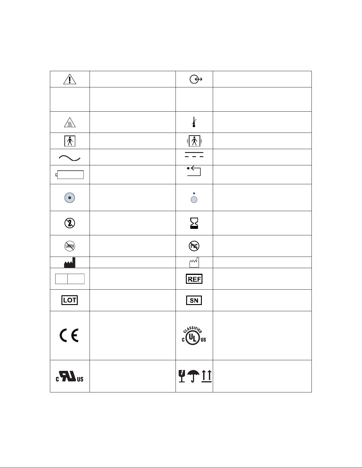
1.3 Key to Symbols
USB-A
Caution: Consult
Accompanying Documents
Universal Serial Bus:
Type A
Caution: Hot Surface
Type BF Equipment
USB-B
Data I/O, RS-232 Serial Port
Universal Serial Bus:
Type B
Storage Temperature Limits
Type BF Equipment
Defibrillator-proof
EC REP
Alternating Current (A/C)
Battery Location
Monitor Power ON
Do not Reuse
Latex-free product
Manufacturer
Authorized Representative
in the European Community
Batch Code
Conformité Européenne
(CE) Marking of
Conformity to European
Medical Device Directive.
CE
represents the
XXXX
Notified Body number
Recognized under the
Component Recognition
Program of Underwriters
Laboratories Inc.
Direct Current (D/C)
Reset Button
Monitor Power OFF or Standby
Mode
Use by
YYYY-MM-DD or
YYYY-MM
PVC-free product
Date of Manufacture
Catalog Number
Serial Number
Classified by Underwriters
Laboratories Inc.® with respect
to electric shock, fire and
mechanical hazards only, in
accordance with
UL 60601-1 and IEC60601-2-26
Packaging Labeling:
Fragile, Do Not Get Wet, and
This Side Up
Figure 1 - Symbol Key (page 1 of 3)
1-6
Page 19
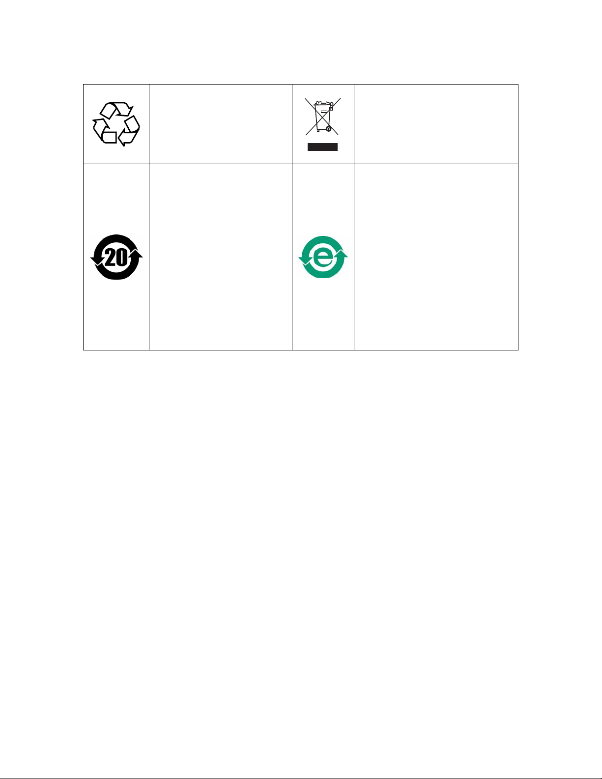
SECTION 1 SAFETY PRECAUTIONS
______________________________________________________________________
Crossed out wheelie bin indicates
Recyclable
Product marked with a
number contains certain
toxic or hazardous
substances or elements, and
can be used safely during its
Environment-Friendly Use
Period (EFUP). The
product should be recycled.
The Environment-Friendly
Use Period is valid only
when the product is
operated under the
conditions defined in the
product manual. **
*Contact Aspect Medical Systems International B.V. for a Return Materials Authorization
(RMA) number. According to the WEEE Directive 2002/96/EC, all waste electrical and
electronic equipment (EEE) should be disposed of and collected separately and treated
according to the best available and environmentally friendly techniques.
EEE contains hazardous substances to the (human) environment but also EEE is a valuable
resource of new raw materials. Therefore it is important to collect WEEE separately from
other waste.
Aspect Medical products are subject to the Directive and we therefore urge you to dispose of the equipment
separately and make sure that it is treated at an electronics recycler. Please contact your municipality or the
nearest collection site and dispose of waste equipment there and make sure the discarded equipment does not
end-up in the ‘normal’ household waste.
** Refer to www.aspectmedical.com for Material Declaration Data Sheets.
Figure 1 - Symbol Key (Page 2 of 3)
separate treatment from general
waste at end of life *
Product marked with the “e”
does not contain any toxic or
hazardous substances or
elements, and is green and
environmental. The product can
be recycled. **
1-7
Page 20
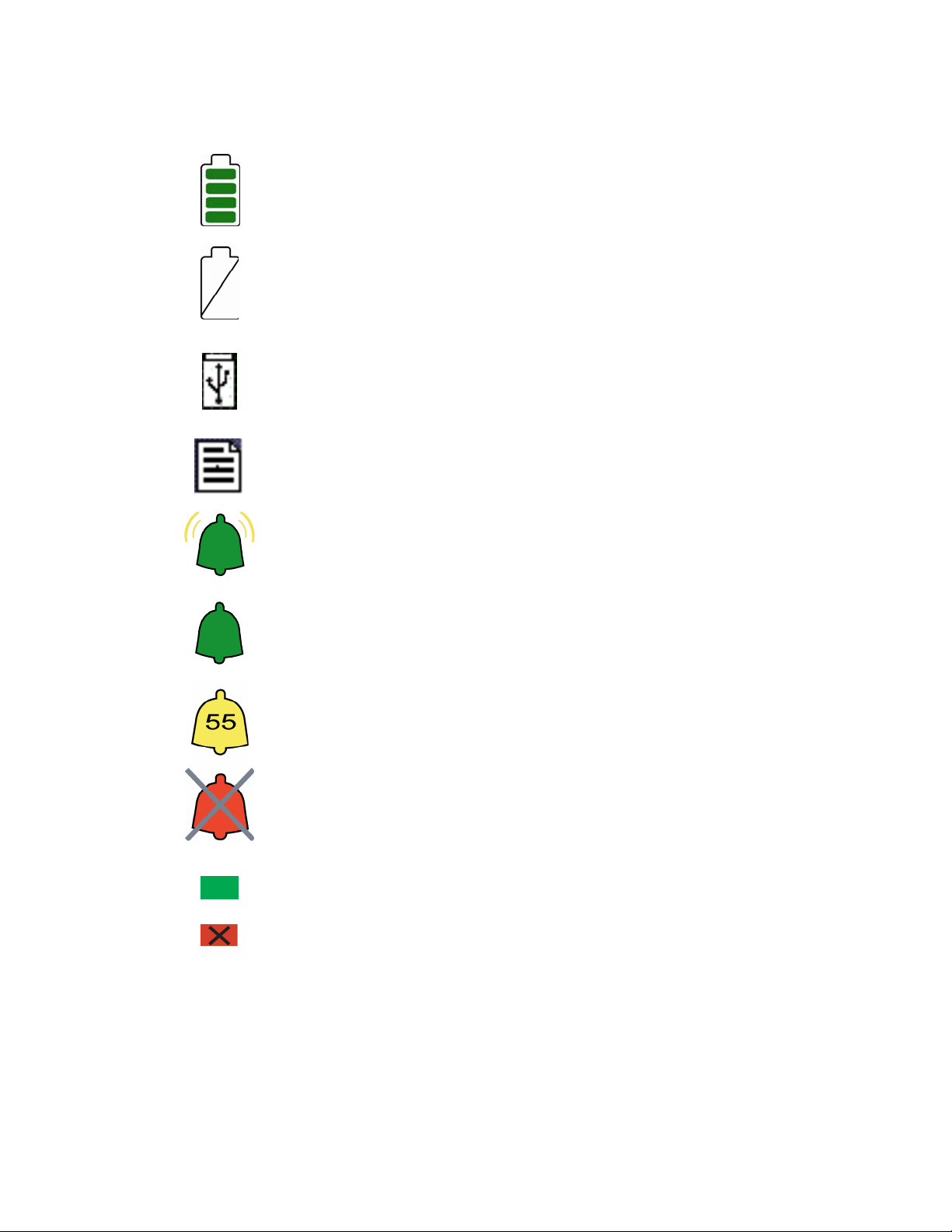
SECTION 1 SAFETY PRECAUTIONS
______________________________________________________________________
Operating on Battery
No Battery is Installed in Monitor
USB Drive: Data Export is in Progress
A Printable File Is Being Transferred to the USB Drive
Ringing Bell Icon - High Priority Alarm Sounding
Green Bell Icon - Alarms Active
Yellow Bell with Countdown Timer - Alarms Paused
Red Bell with ‘X’ - Alarms Silenced
A green box denotes ON or active condition.
A red box with an ‘X’ denotes OFF or cancel.
Figure 1 - Symbol Key (page 3 of 3)
1-8
Page 21

SECTION 2 INSTALLATION AND PREPARATION FOR USE
______________________________________________________________________
2 INSTALLATION AND PREPARATION
FOR USE
____________________________________________________
INTRODUCTION
This section provides installation instructions for the BIS VISTA Monitor, BISx, and
accessories. It includes:
• Installation checklist
• Proper environment
• Required equipment and supplies
• Cable connections
• Start and shutdown procedures
• Initial menu settings
2.1 BIS VISTA Monitor Installation and Checkout
1. Open packages and inspect for all components:
• Monitor (P/N 185-0151)
• Power cord
• Pole clamp
• BISx (P/N 185-0145-AMS)
• PIC (Patient interface cable, connects BISx to patient) (P/N 186-0107)
Sensors are sold separately. For a list of available sensors please contact Aspect Medical
Systems, Inc. or your local distributor.
2. Connect power cable to monitor, plug power plug into appropriate wall outlet.
• Verify that light to right of ON/Standby button is yellow.
3. Start up monitor by pressing the ON/Standby button (lower right corner).
• Verify that light to right of ON/Standby button is green.
• Verify all self-tests complete successfully.
• Verify next screen says “Connect BISx.”
4. Connect BISx with PIC to monitor.
• Verify screen says, “BISx Initialization Complete.”
• Verify screen says “Connect sensor or cable.”
5. Connect PIC and sensor.
• Verify SENSOR CHECK begins.
6. Disconnect power cord from monitor.
• Verify ‘OPERATING ON BATTERY BACKUP’ is displayed.
2-1
Page 22

SECTION 2 INSTALLATION AND PREPARATION FOR USE
______________________________________________________________________
• Verify battery icon displays below BIS number.
7. Reconnect power cord.
• Verify battery icon is not displayed below BIS banner.
• Verify “OPERATING ON BATTERY BACKUP” is not displayed.
8. End of install.
2.2 Environment
2.2.1 Shipping and Storage Environment
The monitor and its accessories can be stored or shipped within the following environmental
limits. Note that these limits apply to non-operational storage and shipping situations.
Temperature -10°C to +60°C
Humidity 15% to 95% (non-condensing)
Pressure 800 mm Hg (1500 feet below sea level) to 360mm Hg (20,000 feet
above sea level)
Protect the monitor from sudden temperature changes that can lead to condensation within
the instrument. To minimize condensation, avoid moving the system between heated
buildings and outside storage. Once moved inside, allow the monitor to stabilize in the
unopened shipping container at the inside ambient temperature before unpacking and
placing into service. Before operation, wipe down all visible condensation and allow the
system to reach equilibrium at room temperature.
2.2.2 Operating Environment
The BIS VISTA Monitoring System is not designed for use in areas containing flammable
gases or vapors.
WARNING:
EXPLOSION HAZARD: DO NOT USE THE BIS VISTA SYSTEM
IN A FLAMMABLE ATMOSPHERE OR WHERE
CONCENTRATIONS OF FLAMMABLE ANESTHETICS MAY
OCCUR.
MONITOR IS NOT DESIGNED FOR USE IN MRI
ENVIRONMENT.
The BIS VISTA monitor is designed to operate safely under the following conditions.
Conditions outside these ranges could affect reliability.
Temperature 0°C to +40°C
Humidity 15% to 95% (non-condensing)
Pressure 800 mm Hg (1500 feet below sea level) to 360mm Hg (20,000 feet
above sea level)
2-2
Page 23

SECTION 2 INSTALLATION AND PREPARATION FOR USE
______________________________________________________________________
2.2.3 Power Requirements and System Grounding
The BIS VISTA Monitoring System requires a power source of 100-240 VAC, 50-60Hz.
Current consumption is 0.7 ampere maximum.
To protect operating personnel and patients, the monitor must be properly grounded.
Accordingly, the monitor is equipped with a hospital grade line cord. The power cord
grounds the system to the power line ground when plugged into an appropriate three-wire
receptacle.
WARNING:
USE ONLY THE POWER CORD SUPPLIED BY THE
MANUFACTURER. NEVER ADAPT THE PLUG FROM THE
MONITOR TO FIT A NON-STANDARD OUTLET.
U.S.A. REQUIREMENT: FOR PROPER GROUNDING, THE
POWER RECEPTACLE MUST BE A THREE-WIRE GROUNDED
OUTLET. A HOSPITAL GRADE OUTLET IS REQUIRED.
NEVER ADAPT THE THREE-PRONG PLUG FROM THE
MONITOR TO FIT A TWO-SLOT OUTLET. IF THE OUTLET
HAS ONLY TWO SLOTS, MAKE SURE THAT IT IS REPLACED
WITH A THREE-SLOT GROUNDED OUTLET BEFORE
ATTEMPTING TO OPERATE THE MONITOR.
IF THE INTEGRITY OF THE EXTERNAL PROTECTIVE
EARTH GROUND IS IN DOUBT, THE BIS VISTA MONITOR
SHALL BE OPERATED FROM ITS INTERNAL BATTERY
POWER SOURCE ONLY.
2.2.4 Electromagnetic Compatibility Requirements
The BIS VISTA Monitoring System should be used only with the power cord and
accessories recommended and supplied by Aspect Medical Systems, Inc. The system must be
installed and put into use according to the specifications described in Section 8.2
“Electromagnetic Compatibility Specifications.”
Caution:
The BIS VISTA system complies with the electromagnetic
compatibility requirements of IEC 60601-1-2. Operation of this device
may affect or be affected by other equipment in the vicinity due to
electromagnetic interference (EMI). If this occurs:
• Increase separation between devices
• Re-orient device cabling
• Plug devices into separate outlet circuit branches
Refer to Section 8.2 “Electromagnetic Compatibility Specifications.”
2-3
Page 24
SECTION 2 INSTALLATION AND PREPARATION FOR USE
______________________________________________________________________
2.2.5 Site Preparation: Mounting the Monitor
Aspect Medical Systems, Inc. strongly recommends permanent mounting of the BIS VISTA
monitor to the anesthesia machine to enhance safety and facilitate ease-of-use. Please
contact your local representative or Aspect to discuss mounting options.
WARNING:
BE SURE THE MONITOR IS MOUNTED SECURELY IN PLACE
TO AVOID PERSONAL OR PATIENT INJURY.
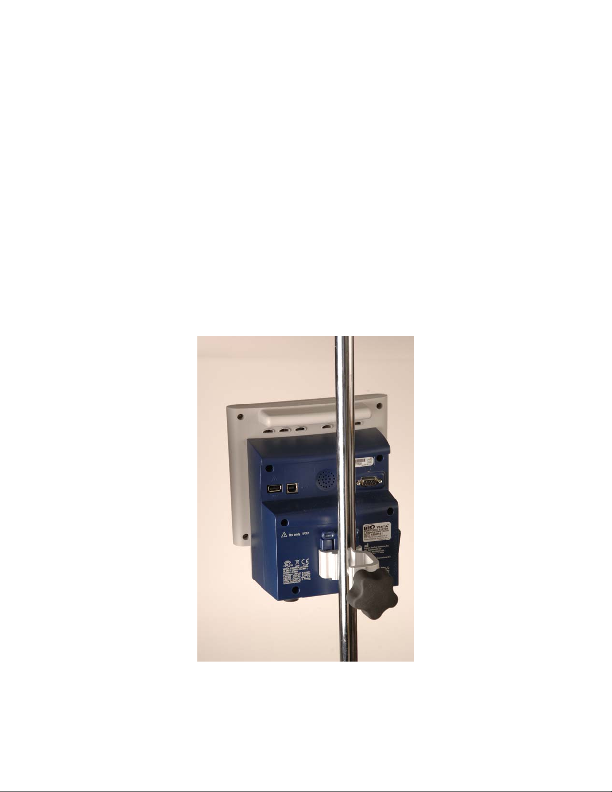
2.2.5.1 Mounting the Monitor using the Pole Clamp
To mount the monitor to a secure vertical pole (1/2" - 1½" in diameter):
1. Place pole within clamp bracket and tighten screw using the black finger knob. Make
sure that there is enough space above the clamp so that you have a few inches to slide
the monitor in from above.
2. Line up the clamp shoe (on back of monitor) with the slot on pole clamp and slide
monitor down to fit. The bottom of the clamp shoe should be seen well below the
bottom of the pole clamp, and the monitor should snap securely into place.
Figure 2 - Pole Clamp
To remove the monitor, press tab on top of clamp shoe before sliding monitor up.
2-4
Page 25

SECTION 2 INSTALLATION AND PREPARATION FOR USE
______________________________________________________________________
The pole clamp may be locked onto the monitor so that the two do not get separated. To do
this:
1. Line up the clamp shoe (on back of monitor) with the slot on pole clamp and slide
monitor down to fit. The bottom of the clamp shoe should be seen well below the
bottom of the pole clamp and the monitor should snap securely into place.
2. Make sure that set screw hole on pole clamp aligns with corresponding hole on clamp
shoe.
3. Remove black knob screw from pole clamp.
4. Using the Allen wrench supplied, secure pole clamp to monitor with the set screw
provided.
5. Replace black knob screw.
6. To attach to pole, place pole within clamp bracket and tighten screw using the black
finger knob.
2.2.5.2 Optional Mounting Accessories
For information on optional mounting accessories, request Aspect’s “Monitor Mounting
Solutions” booklet (part number 070-0031).
2-5
Page 26
SECTION 2 INSTALLATION AND PREPARATION FOR USE
______________________________________________________________________
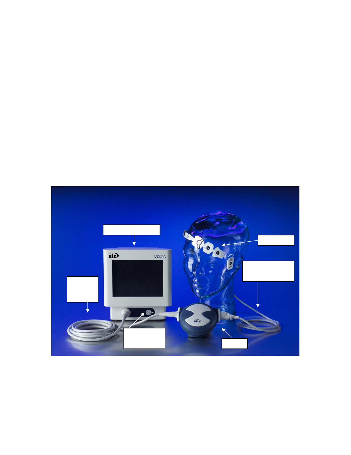
2.3 The BIS VISTA Monitoring System –
Equipment and Supplies
The BIS VISTA Monitoring System consists of the following basic components:
• BIS VISTA Monitor (P/N 185-0151)
• BISx (P/N 185-0145-AMS)
• Patient Interface Cable (PIC) (P/N 186-0107)
• BIS Sensor
• Detachable Power Cord
Sensors are sold separately. For a list of available sensors please contact Aspect Medical
Systems, Inc. or your local distributor.
A pole clamp is also included; however its use is optional. Contact Aspect or your local
representative for information on additional equipment and accessories.
BIS VISTA Monitor
BIS Sensor
Patient Interface
Cable (PIC)
Monitor
Interface
Cable
ON/Standby
Button
BISx
Figure 3 - The BIS VISTA Monitoring System
2-6
Page 27

SECTION 2 INSTALLATION AND PREPARATION FOR USE
______________________________________________________________________
2.3.1 BIS VISTA Monitor
2.3.1.1 Front Panel
The front panel of the BIS VISTA monitor contains the Touch Screen, BISx port and the
ON/Standby button. See Figure 3.
2.3.1.2 Touch Screen
The BIS VISTA monitor is designed so that all controls (with the exception of the
ON/Standby button) are accessible by touching a designated area on the monitor screen.
This area is called a touch key. The touch keys are designed to function even when the user
is wearing examination gloves.
2.3.1.3 ON/Standby button
The ON/Standby button is located in the lower right corner of the monitor and indicates
whether the monitor is ON or in Standby mode. When the small LED light to the right of
the ON/Standby button is green, the unit is running and providing power to the BISx.
When it is yellow, the battery is charging and the system is in Standby mode. When it is not
lit, no A/C power is available to the unit; pressing the ON/Standby button will start up the
monitor using the battery.
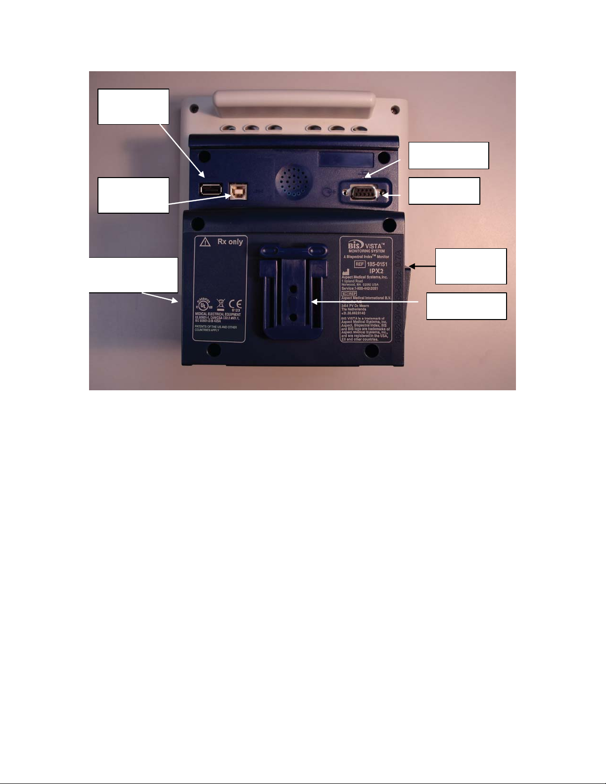
2.3.1.4 Rear Panel
The rear panel components are pictured in Figure 4. They include: two USB ports (Type A
and B), the clamp shoe, an RS-232 port, the Reset button, the Battery/Power Supply cover,
and the power cord receptacle.
2-7
Page 28
SECTION 2 INSTALLATION AND PREPARATION FOR USE
______________________________________________________________________
USB Port
(Type A)
Reset Button
USB Port
(Type B)
Battery/Power
Supply
Cover
Serial Port
Power Cord
Receptacle
Clamp Shoe
Figure 4 - Rear Panel
There are two USB ports on the rear of the monitor. The Type A port is used to export
data to a removable drive. It is also used to update monitor and BISx software.
The clamp shoe allows the monitor to slide into the pole clamp so that it can be attached
to a ½" – 1 ½" diameter vertical pole.
The RS-232 serial port can be used to transfer data from the monitor.
WARNING:
WHEN CONNECTING EXTERNAL EQUIPMENT (e.g., DATA
CAPTURE COMPUTER), THE SYSTEM LEAKAGE CURRENT
MUST BE CHECKED AND MUST BE LESS THAN THE IEC
60601-1-1 LIMIT.
THE USE OF ACCESSORY EQUIPMENT NOT COMPLYING
WITH THE EQUIVALENT SAFETY REQUIREMENTS OF THIS
EQUIPMENT MAY LEAD TO A REDUCED LEVEL OF SAFETY
OF THE RESULTING SYSTEM. CONSIDERATION RELATING
TO THE CHOICE SHALL INCLUDE:
• USE OF THE ACCESSORY IN THE PATIENT VICINITY
2-8
Page 29

SECTION 2 INSTALLATION AND PREPARATION FOR USE
______________________________________________________________________
• EVIDENCE THAT THE SAFETY CERTIFICATION OF
THE ACCESSORY HAS BEEN PERFORMED IN
ACCORDANCE TO THE APPROPRIATE IEC 60601-1
AND/OR IEC 60601-1-1 HARMONIZED NATIONAL
STANDARD.
Under normal operation, power is cycled through the ON/Standby button. The Reset
button can be used to reset the software functions of the BIS monitor (and the BISx if it is
attached) in the unlikely case that it is required. See Section 6.4. “Using the Reset Button.”
The Battery/Power Supply cover contains the BIS VISTA monitor’s power supply and
allows access to its battery.
The power cord receptacle, located on the side of the Battery/Power Supply cover, is used
to plug in the power cord provided by the manufacturer. It provides power to the monitor
and to the BISx when it is attached.
Caution:
The BIS VISTA Monitoring System complies with the electromagnetic
compatibility requirements of IEC 60601-1-2. Operation of this device
may affect or be affected by other equipment in the vicinity due to
electromagnetic interference (EMI). If this occurs:
• Increase separation between devices
• Re-orient device cabling
• Plug devices into separate outlet circuit branches
Refer to Section 8.2 “Electromagnetic Compatibility Specifications”.
2.3.1.5 Integral Battery
A rechargeable lithium ion battery inside the monitor provides approximately 45 minutes of
back-up power when power cannot be supplied via the power cord. Recharge time is
approximately 6 hours. The battery charges continually as long as the unit is plugged into
A/C power.
When the system is running on battery, a battery icon displays indicating the battery status. A
battery icon with four green bars indicates that the battery is fully charged. When the battery
reaches a low power condition, the monitor beeps and the battery symbol displayed on the
screen changes color. In addition, a “Battery Voltage Low” message blinks in the Message
area of the screen.
Caution:
Check the battery periodically by operating a BIS VISTA monitor that
has been disconnected from the wall socket and that has been charged
to full capacity (at least 6 hours of charge time). After long periods of
storage, charge the battery for 6 hours to assure full capacity. If the
BIS VISTA monitor fails to operate reliably from the battery for
approximately 45 minutes, battery replacement is required.
2-9
Page 30
SECTION 2 INSTALLATION AND PREPARATION FOR USE
______________________________________________________________________
The BIS VISTA monitor contains an internal lithium ion battery. The
battery must be removed by a qualified service technician and
disposed of or recycled in accordance with the national laws of the
country. Contact Aspect Medical Systems, Inc. or the local distributor
for a replacement battery: Aspect part number 186-0208.
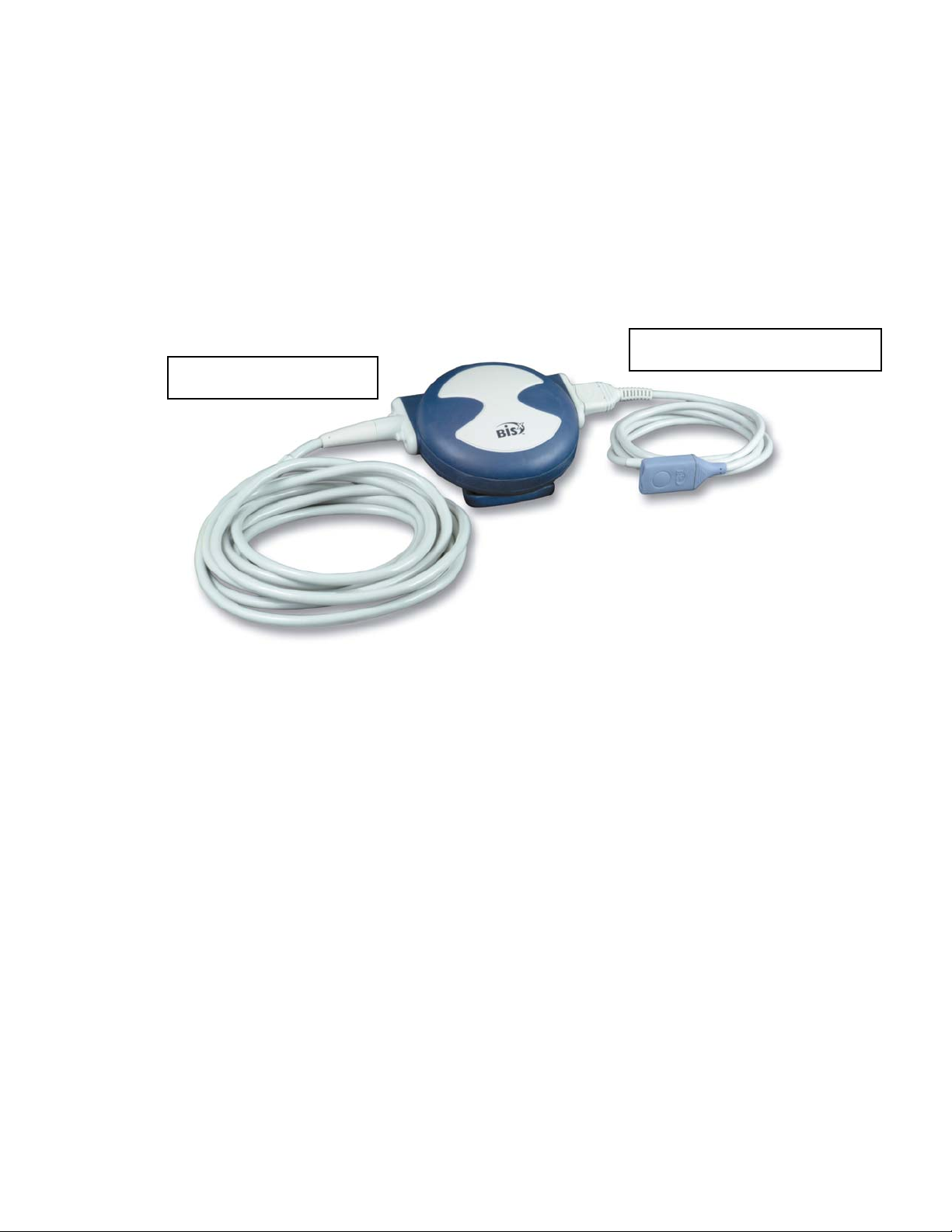
2.3.2 BISx
Patient Interface Cable (PIC)
Monitor Interface Cable
Figure 5 - BISx and PIC
The BISx receives, filters, and processes patient EEG signals. It is located close to the
patient's head where the EEG signal is less subject to interference from other medical
equipment.
The BISx is shown in Figure 5. Its long flexible Monitor Interface Cable connects to the
front of the monitor. The Patient Interface Cable (PIC) connects the BIS sensor to the
BISx.
The attachment clip on the BISx is used to secure it in a convenient location near the
patient's head.
2-10
Page 31

SECTION 2 INSTALLATION AND PREPARATION FOR USE
______________________________________________________________________
WARNING:
DUE TO ELEVATED SURFACE TEMPERATURE, DO NOT
PLACE BISx IN PROLONGED DIRECT CONTACT WITH
PATIENT’S SKIN, AS IT MAY CAUSE DISCOMFORT.
Caution:
Do not open BISx for any reason. The seal to prevent liquids from
entering the BISx may be damaged if opened. Service or repairs must
be performed only by qualified biomedical technicians.
2.3.3 Patient Interface Cable (PIC)
Aspect's BIS Sensor Patient Interface Cable (PIC) (see Figure 3) connects the BISx to the
BIS sensor.
2.3.4 BIS Sensors
The sensor is the single use component of the BIS Monitoring System and should be
replaced after each use. For details on how to apply the sensor to the patient and how to
connect to the BIS Monitoring System, refer to the BIS Sensor’s instructions for use. All
sensors, including the BIS Extend Sensor, utilize the monitor’s saved settings (such as
smoothing rate).
2.4 Cable Connections
After you have familiarized yourself with the safety information in the introductory section
of this manual and have prepared a suitable environment, follow these steps to prepare the
BIS VISTA system for operation.
1. Connect the BISx to the monitor
Holding the cylindrical connector with the flat side up, plug the BISx Monitor
Interface Cable into the BISx port on the front of the monitor.
Once connected, the BISx need not be disconnected again. However, if you wish to
disconnect the BISx cable from the monitor, carefully grasp the connector and pull.
DO NOT pull on the cable.
2. Connect the PIC to the BISx
Attach the gray connector of the Patient Interface Cable to the BISx.
Notes:
Connect with the BIS logo facing up for proper pin alignment. To disconnect the PIC, grasp
the connector housing and pull firmly. DO NOT pull apart by the cable wire.
2-11
Page 32

SECTION 2 INSTALLATION AND PREPARATION FOR USE
______________________________________________________________________
2.5 Start Procedure / Standby Mode
2.5.1 Starting the Monitor for the First Time
To start the instrument for the first time, after it has been reset with the RESET button, or
after battery replacement:
1. Attach one end of the power cord to the receptacle on the left side of the monitor.
2. Plug the other end of the power cord into a properly grounded hospital-grade AC
power outlet. A yellow light illuminates to the right of the ON/Standby button.
3. Press the ON/Standby button. The light changes to green and diagnostics tests run
to verify that the system is operating properly. A beep indicates that the tests are
complete. If there is a problem, the system halts and an error message appears. Error
messages are explained in the Troubleshooting section of this manual.
When not in use, the monitor should be placed in Standby mode. To put the system in
Standby mode, press and hold the ON/Standby button for two seconds before releasing.
The light will change from green to yellow. If the monitor is running on battery, the light will
go off completely.
2.5.2 Starting the Monitor from Standby Mode
When the monitor is in Standby mode (yellow light), you may start it by pressing the
ON/Standby button. The light will change to green.
When not in use, the monitor should be placed in Standby mode. To put the system in
Standby mode, press and hold the ON/Standby button for two seconds before releasing.
The light will change from green to yellow. If the monitor is not connected to A/C power,
the light will go off completely.
2.6 Initial Menu Settings
Before using the BIS VISTA monitor for the first time, you may need to select the proper
language and set the current date and time. Other setting options are discussed in detail in
Section 3.
The BIS VISTA monitor utilizes a touch screen. To access the Menus, press the
[MENU] icon on the left side of the screen. Press the [Next] or [Previous] touch
keys to scroll through the menu options. At any time you may press the [HOME]
touch key to return to the main display screen.
2-12
Page 33

SECTION 2 INSTALLATION AND PREPARATION FOR USE
______________________________________________________________________
2.6.1 Language Selection
The BIS VISTA monitor is designed to support multiple languages. If the screen does not
display the desired language, follow these steps:
To change the language:
1. Press [MENU].
2. Press [Next] to go to the second menu, then [Next] again to go to the third menu.
3. Press [Language]. The current language is displayed.
4. Use the [+] or [-] keys to scroll through the list of languages until the desired
language appears. All screens will now display in the selected language.
5. Press [HOME] to return to the main screen.
2.6.2 Date and Time
To set the current date and time:
1. Press [MENU].
2. Press [Next] to go to the second menu, then [Next] again to go to the third menu.
3. Press [Date and Time]. A new screen displays the current date and time. “Day” is
displayed in blue letters.
4. Use the up and down arrows to set the day of the month.
5. Press [Month]. “Month” is displayed in blue letters.
6. Use the up and down arrows to set the month.
7. Repeat this process for the “Year,” “Hour,” “Minute” and “Second” displays.
8. When you have finished, you may press [Return to Previous Menu] or press
[HOME] to return to the main screen.
Note:
The time/date is initially set for the Eastern Standard or Eastern Daylight Time zone (USA).
It will be necessary for you to change the time twice per year using the Time/Date feature if
you are located in a time zone that alters its clocks at the beginning or end of Daylight
Savings Time.
2.6.3 View/Save Settings
The BIS VISTA monitor will always start up configured to settings that have been saved in
memory.
To save the current configuration settings,
1. Press [MENU].
2. Press [View/Save Settings]. The current settings display.
3. Press [Save Active]. The message, “Settings Saved” appears. The settings displayed
will be saved except as noted below.
4. Press [Previous] or [HOME] to exit.
Notes:
The “Save Active” option is disabled when in Battery Backup-Low Power condition.
The following settings are not saved by the “Save Active” option: Impedance Checking
(always returns to ON), Filters (returns to ON), and Display Type (returns to BIS).
2-13
Page 34

SECTION 2 INSTALLATION AND PREPARATION FOR USE
______________________________________________________________________
Settings are set and saved for the current Monitor Mode only. See 3.5.10 “Monitor Mode.”
See Section 3.5.6 “View/Save Settings” for instructions on restoring factory default values.
2-14
Page 35

SECTION 3 OPERATING THE BIS VISTA MONITORING SYSTEM
______________________________________________________________________
3 OPERATING THE BIS VISTA
MONITORING SYSTEM
_______________________________________________________________
INTRODUCTION
This section covers:
• Preparing for operation
• The sensor check
• The monitor screen display
• Software menus and menu selections
• Reviewing stored data
• The EEG display
• Ending a case
Read this section before operating the monitor in a clinical setting.
3.1 Preparing for Operation
After you have familiarized yourself with the safety information in the introductory section
of this manual, prepared a suitable environment, properly connected the BISx and PIC
cables, and completed the initial settings described in Section 2, follow these steps to prepare
the BIS VISTA Monitoring System for operation.
1. Startup and System Check
Press the ON/Standby button on the lower right corner of the monitor to start the monitor.
The light changes from yellow to green, and the system initiates a self-test to make sure that
all equipment is operating properly.
2. Attach BIS Sensor to Patient
Prepare sensor site and place the BIS sensor on the patient in accordance with the
instructions included on the sensor packaging.
Caution:
The BIS VISTA Monitoring System has been designed to operate with
a BIS sensor. The sensor is a silver/silver chloride electrode array that
utilizes Aspect's patented Zipprep technology and uses a proprietary
connector. Use of other electrodes is not recommended.
3-1
Page 36

SECTION 3 OPERATING THE BIS VISTA MONITORING SYSTEM
______________________________________________________________________
WARNINGS!
THE CONDUCTIVE PARTS OF ELECTRODES OR SENSOR
AND CONNECTORS SHOULD NOT CONTACT OTHER
CONDUCTIVE PARTS, INCLUDING EARTH.
TO REDUCE THE HAZARD OF BURNS DURING USE OF
HIGH-FREQUENCY SURGICAL EQUIPMENT, THE SENSOR
OR ELECTRODES SHOULD NOT BE LOCATED BETWEEN
THE SURGICAL SITE AND THE ELECTRO-SURGICAL UNIT
RETURN ELECTRODE.
THE SENSOR MUST NOT BE LOCATED BETWEEN
DEFIBRILLATOR PADS WHEN A DEFIBRILLATOR IS USED
ON A PATIENT CONNECTED TO THE BIS VISTA SYSTEM.
TO MINIMIZE THE RISK OF PATIENT STRANGULATION,
THE PATIENT INTERFACE CABLE (PIC) MUST BE
CAREFULLY PLACED AND SECURED.
3. Secure the BISx
Using the attachment clip, secure the BISx to a convenient location near the patient's head.
3-2
Page 37

SECTION 3 OPERATING THE BIS VISTA MONITORING SYSTEM
______________________________________________________________________
4. Attach the BIS Sensor to the PIC
Release
Button
PIC Sensor
Connector
Figure 6 - Connecting the PIC
To insert the sensor into the PIC, line up as shown and insert the sensor tab into the
PIC sensor connector until an audible “click” is heard. The blank side of the sensor tab
(i.e. the side without the computer chip) should be facing up.
The Sensor Integrity Check is initiated each time that a sensor is connected to the PIC to
make certain that a valid, unexpired sensor is in use.
Sensor tab
3.2 Sensor Check
The Sensor Check tests the impedance of each electrode on the BIS sensor to verify that it is
within an acceptable range for monitoring. A Sensor Check is initiated automatically when
the sensor and PIC are connected to the BISx. It may also be initiated by the user by
pressing the [Sensor Check] touch key.
The message, “Sensor Check in Progress” appears. When the sensor successfully passes the
test, the Main Screen displays and monitoring begins.
3-3
Page 38

SECTION 3 OPERATING THE BIS VISTA MONITORING SYSTEM
______________________________________________________________________
If the sensor does not immediately pass the test, or if the user has manually initiated the test,
the Sensor Check Graphic Screen displays. This screen shows the sensor with each electrode
numbered. Colors indicate the status of each electrode:
• Hollow circle – No status is available. The electrode label will appear after a few
seconds.
• Green circle with Checkmark – The electrode impedance is within the acceptable
range. When all circles are green, monitoring can begin.
• Red blinking circle with ‘X’ – The electrode impedance is not within the acceptable
range. Press the edges of the sensor to ensure adhesion and then press each circle for
5 seconds to ensure proper contact. Check all connections. If the problem persists,
remove sensor, clean skin thoroughly, and reapply sensor or apply new sensor in
accordance with instructions on the sensor packaging.
• Gray circle with Question Mark - The electrode impedance cannot be determined
due to electrical interference (noise) from another source. Monitoring will not
commence until the source of the noise has been removed and all electrodes have
passed the sensor check.
If the user has requested the Sensor Check and all electrodes pass the test, the circles return
to their original display color (blue) and the label, “PASS” displays at the bottom of the
screen.
Figure 7 - Sensor Check Graphic Screen (Values not Shown)
If user action is required, messages in the message region of the screen issue instructions.
The monitor continues updating the values until all impedance values are acceptable. The
[EXIT] touch key allows the user to exit the screen before the test has completed, however,
the Sensor Check impedance test must be successfully completed before normal processing
resumes.
For more detailed impedance information, press the [Show Values] touch key.
3-4
Page 39

SECTION 3 OPERATING THE BIS VISTA MONITORING SYSTEM
______________________________________________________________________
Figure 8 - Sensor Check Graphic Screen with Values Shown
In this display, the impedance value for each electrode, in kilo ohms, appears on the screen
along with its status:
PASS - An electrode passes if the impedance for that electrode is less than 7.5 kilo ohms.
The ground electrode (electrode #2) must be less than 30 kilo ohms to pass.
HIGH - An electrode is labeled “HIGH” if its impedance value is above 7.5 kilo ohms (30
kilo ohms for the ground electrode). As long as the combined impedance of electrodes #1
and #3 and the combined impedance of electrodes #1 and #4 are less than 15 kilo ohms,
and the ground electrode is less than 30 kilo ohms, the sensor check will be considered
successful.
NOISE - If the signal from the electrode goes beyond the measurable range, the label
“NOISE” displays.
POOR CONTACT - If the impedance check indicates that the electrode is not in contact
with the patient, the label “POOR CONTACT” displays.
To return to the previous display, press the [Hide Values] touch key.
To save this screen as the default screen, return to the menu system, press the [View/Save
Settings] touch key, then press [Save Active].
3-5
Page 40

SECTION 3 OPERATING THE BIS VISTA MONITORING SYSTEM
A
A
T
T
______________________________________________________________________
3.3 BIS Trend Data Screen
Once the sensor check has successfully completed, monitoring begins and the corresponding
information appears on the screen.
BIS Value
Primary Variable
Name
BIS Trend
Unit Labels
larm Pause/Silence
Touch Key
Signal Quality Indicator EMG Indicator EEG Waveform
MESSAGE REGION
Current Time and Date
Case ID
Secondary Variable Name
Menu/Home
Touch Key
Sensor Check
Touch Key
arget Range
Secondary Variable
Unit Labels
Review
Secondary
rtifact
Snapshot
Event Marker
BIS Trend
rend Time Scale
Figure 9 - Screen Features – BIS Trend Data Screen
3.3.1 BIS (Bispectral Index) Value
The current numeric value of the BIS is displayed in the upper left corner of the screen.
The BIS number is displayed and continuously updated during all display modes as long as
signal quality is sufficient.
3.3.2 Signal Quality Indicator
The Signal Quality Indicator (SQI) is a measure of the signal quality for the EEG channel
source and is calculated based on impedance data, artifact, and other variables. It is displayed
in the upper left corner of the screen, to the right of the “BIS” label. Signal quality is optimal
when all five bars of the SQI icon are green. When signal quality is too low to accurately
calculate a BIS value, the BIS value and other trend variables that are adversely affected by
artifact will not be displayed on the screen.
3-6
Page 41

SECTION 3 OPERATING THE BIS VISTA MONITORING SYSTEM
______________________________________________________________________
3.3.3 Electromyograph (EMG) Indicator
The EMG bar graph displays the power (in decibels) in the frequency range 70 - 110 Hz.
This frequency range contains power from muscle activity (i.e., electromyography or
“EMG”) as well as power from other high-frequency artifacts. When the indicator is low, it
indicates that EMG activity is low. BIS monitoring conditions are optimal when the bar
is empty.
1 bar represents power in the 30-38 range
2 bars represent power in the 39-47 range
3 bars represent power in the 48-55 range
4 bars represent power greater than 55.
3.3.4 EEG Waveform Display
Filtered electroencephalogram (EEG) waveforms are displayed above the BIS trend graph
with a sweep rate of 25 millimeters per second and a scale of 25 microvolts (1 channel) or 50
microvolts (2 channels) per division. One or two channels of EEG may be displayed in this
area. EEG filters can be turned off, if desired.
An alternate screen display is available to view the waveforms in a larger format. Refer to
Section 3.7 “EEG Display” for information.
3.3.5 Message Region
The Message Region is a space reserved for status and error messages. These messages are
prioritized so that a high priority message displays before a lower priority message. The
background color of the message indicates its priority:
Message Priority Background Color
High Orange
Medium Yellow
Low Grey
Information only Dark Blue
Diagnostic codes may be displayed above the messages by activating them in the Diagnostic
Menu. Specific error messages are explained in the Troubleshooting section of this manual
(Section 6).
3-7
Page 42

SECTION 3 OPERATING THE BIS VISTA MONITORING SYSTEM
______________________________________________________________________
3.3.6 BIS Trend Graph
The BIS Trend Graph plots the values of the Bispectral Index over time. The BIS trend is
indicated with a thick line and its unit labels appear on the left axis. The name BIS is
displayed above the left corner of the graph and the current date and time display in the
center. (See Figure 9 and Figure 10.)
On the right, a unique Case ID number is displayed. A new case number is assigned when a
new sensor is attached to the PIC and passes the Sensor Check.
If a target range for BIS has been set, the target area displays as either a colored bar or two
horizontal lines showing the upper and lower target ranges (depending on the user setting).
If the BIS value falls outside of the target range, a message displays in the Message Region of
the screen, and if an audible alarm was requested in the target range setup screen, the alarm
sounds (unless alarms have been silenced). The alarm continues to sound until the BIS value
returns to the target range or the alarm is silenced by pressing the alarm touch key. See
Section 3.5.1 for more information.
A secondary variable may be added to the display by selecting “Suppression Ratio,”
“EMG,” “Signal Quality” or “ Bursts/Minute” as a secondary variable in the menu system.
(See Section 3.5.2 “Secondary Variable” for instructions.) The secondary trend is shown with
a thin line and its unit labels appear on the right axis. The secondary trend name is displayed
above the right corner of the graph. Note that Burst Count is only available as a secondary
variable when a BIS Extend Sensor is in use.
During periods of poor signal quality, an artifact bar appears along the horizontal axis at the
bottom of the graph. When signal quality is considered too low to calculate a BIS value, the
bar becomes bright yellow and any trend variables that are adversely affected by artifact will
not be displayed.
A Data Snapshot may be taken to save up to 10 minutes of data leading up to a significant
event. A Data Snapshot Marker (a camera icon) displays at the bottom of the BIS Trend
Graph at the time the snapshot was taken. Only one set of data is saved in memory at a time.
When a second snapshot is taken, the snapshot marker from the first snapshot changes from
a camera to a diamond and its data are overwritten. Snapshot data may be saved to a
removable drive. To export snapshot data, see Section 3.5.11 “Export Data.” To save
snapshot data in a printable (PDF) format, see Section 3.5.13 “Print (Snapshot).”
If desired, EEG may be displayed in place of the BIS Trend Graph by selecting the EEG
display mode in the menu system. See section 3.5.5 “BIS/EEG Display Modes” for details.
During the sensor check procedure, this area of the screen is used to issue instructions and
report current status.
3-8
Page 43

SECTION 3 OPERATING THE BIS VISTA MONITORING SYSTEM
t
______________________________________________________________________
Extend
Mode
Indicator
Battery
Icon
Figure 10 - BIS Trend Data Screen with Battery Icon, Target Range, SR, and Burst
Burst Coun
Count
Suppression Ratio
Target
Range
3.3.7 Additional Screen Information
3.3.7.1 Battery Icon
The battery icon is displayed below the BIS number when the monitor and BISx are running
on battery power. When the battery icon contains four green bars, the battery is fully
charged. When the icon turns orange, the battery is nearly depleted.
If an empty battery icon displays on the screen with a slash across it, there is no battery in
the monitor.
3.3.7.2 USB Export Icon
The USB Export icon is displayed below the BIS number during data export to a
removable USB drive inserted in the rear of the monitor.
3-9
Page 44

SECTION 3 OPERATING THE BIS VISTA MONITORING SYSTEM
______________________________________________________________________
3.3.7.3 Print Icon
The Print icon is displayed below the BIS number while printable files are being
written to a removable USB drive inserted in the rear of the monitor.
3.3.7.4 Extend Mode
The message, “EXTEND MODE ON,” displays below the BIS number when a BIS Extend
Sensor is in use. Note that the monitor automatically changes to the smoothing rate that was
set in Mode II (ICU) when a BIS Extend Sensor is attached.
3.3.7.5 Suppression Ratio (SR) Number
The Suppression Ratio (SR) is displayed in the upper right corner of the screen only when it
has been requested by the user. Suppression ratio is a calculated parameter designed to
indicate when an isoelectric (flatline) condition may exist. Suppression ratio is the percentage
of time over the last 63-second period that the signal is considered to be in the suppressed
state. For example: SR=11 (isoelectric over 11% of the last 63 second review).
When SR reaches 100%, the message “Isoelectric EEG Detected” will notify the user.
Suppression ratio can be plotted over time as a secondary trend on the BIS Trend Graph.
3.3.7.6 Burst Count (Bursts/Minute)
When a BIS Extend Sensor is in use, the Burst Count is displayed above the EEG waveform
display. Burst Count is an alternative method of quantifying suppression, reported as the
number of EEG bursts per minute. The system defines a “burst” as a short period of EEG
activity, preceded and followed by periods of inactivity. When the signal quality is low or
when the Suppression Ratio is less than 5, the Burst Count is not displayed.
The Burst Count may also be graphed as a secondary variable on the BIS Trend Graph.
3-10
Page 45

SECTION 3 OPERATING THE BIS VISTA MONITORING SYSTEM
______________________________________________________________________
3.4 Main Screen Touch Keys
3.4.1 Alarm Touch Keys
Alarms sound to alert the user to possible problems with the patient or the equipment.
Alarm conditions are prioritized so that high priority alarms take precedence over lower
priority alarms. The user may silence the currently sounding alarm or silence all alarms.
Alarm volume may be set in the menu system.
When a high priority alarm is sounding, the ringing bell displays.
Pressing this icon silences the current alarm, but does not prevent
other alarms from sounding if another priority alarm condition
should occur. Alarm messages continue to display in the message
Alarm
Sounding
Alarms Active
Alarms Paused
area as long as the alarm condition exists.
A green bell icon indicates that the alarms are active and will sound if
activated. Pressing this icon changes the alarm status to “Alarms
Paused” and the yellow bell icon displays.
A yellow bell indicates that all alarms have been silenced for two
minutes. A countdown timer counts down the seconds until the
alarm sounds again. Pressing this icon changes the alarm status to
“Alarms Silenced” and the red bell icon displays.
Alarms Silenced
The red bell with a solid “X” over it indicates that all alarms have
been silenced indefinitely. Pressing this icon restores the active
alarms and the green bell icon displays.
Figure 11 - Alarm Touch Keys
3-11
Page 46

SECTION 3 OPERATING THE BIS VISTA MONITORING SYSTEM
______________________________________________________________________
3.4.2 Menu, Home, Sensor Check and Review Touch
Keys
The MENU/HOME touch key:
The [MENU] touch key is used to enter the Menu system.
When a menu displays, the [MENU] touch key becomes the
[HOME] touch key.
The [HOME] touch key is used to return to the main display
screen.
The SENSOR CHECK touch key:
This touch key is used to begin a sensor impedance check.
Sensor Check is initiated automatically when the PIC and sensor are
attached to the BISx. You may initiate another check at any time by
selecting this option.
When an automatic check has been completed successfully, the
screen will exit automatically. Otherwise, the user may press the
[EXIT] key at any time to exit. For details on the sensor check
procedure, refer to Section 3.2 “Sensor Check.”
The Review Mode Arrow
This touch key is used to enter Review Mode
Figure 12 - Menu, Home, Sensor Check and Review Mode Touch Keys
3-12
Page 47

SECTION 3 OPERATING THE BIS VISTA MONITORING SYSTEM
______________________________________________________________________
3.5 Menu Selections
Before using the BIS VISTA monitor for the first time, you may want to update the monitor
with your desired screen settings and the current date and time. You should also familiarize
yourself with the various menu options available. This section describes the menu options
available and how they work. These menu options are discussed below. For more detail on
what the settings mean, refer to “BIS Trend Data Screen” in Section 3.3.
3.5.1 Target Range
To access the Target Range, press [MENU].
Figure 13 - Target Range
To aid in patient management, a target range of desired BIS values may be set. When the
Target Range is activated, the selected range displays on the BIS Trend Graph. The BIS
VISTA monitor will notify the user when the patient’s BIS value is outside of the intended
range. The Target Range menu has four components:
1. Activating the Target Range feature so that the range displays on the BIS Trend
Graph.
2. Setting the Target Range display format (colored band or two horizontal lines).
3. Setting the audible alarm to sound when a BIS value falls outside of the range.
4. Setting a Target Range of desired BIS values.
To set the Target Range options, press [Target Range]. The Target Range Screen displays.
1. To activate the Target Range so that it displays on the BIS Trend Graph, or
deactivate it so that it does not, press [Target Range Active].
• When the Target Range is active, a green box displays.
• When the Target Range is inactive, a red box with an ‘X’ displays.
3-13
Page 48

SECTION 3 OPERATING THE BIS VISTA MONITORING SYSTEM
______________________________________________________________________
2. To change the Target Range display format, press the [Target Range Format]
touch key. When the left side of the [Target Range Format] key is illuminated, the
Target Range will display as a colored band. When the right side of the [Target
Range Format] touch key is illuminated, the Target Range displays as a pair of
horizontal lines denoting the upper and lower limits.
3. To activate or deactivate the target alarm, press [Target Alarm].
• A green bell indicates that the Target Alarm is active. Alarms will sound when
the BIS value falls outside of the Target Range, unless the alarms have been
silenced on the main screen.
• A red bell with an ‘X’ indicates that the Target Alarm is inactive. Audible Target
Alarms will not sound.
4. The Target Range upper (High) and lower (Low) limits are displayed between minus
and plus signs. To change the Target Range, use the [+] and [-] touch keys to
increase or decrease the Target Range limits. Each key press will change the limit by
a factor of 5. The system will not allow the difference between the upper and lower
limits to be less than 5. A high value of 100 = none, and a low of 0 = none.
To permanently save this change, press the [View/Save Settings] touch key in the menu
system, then press [Save Active].
3-14
Page 49

SECTION 3 OPERATING THE BIS VISTA MONITORING SYSTEM
______________________________________________________________________
3.5.2 Secondary Variable
To access Secondary Variable, press [MENU].
Figure 14 - Secondary Variable
This option allows the user to add a secondary trend variable to the Trend Graph:
• Selecting “Suppression Ratio” will plot the suppression ratio.
• Selecting “EMG” will plot electromyograph or high frequency signal detection.
• Selecting “Signal Quality” will plot a number (0 – 100) that indicates the quality of
the EEG signal received and processed.
• Selecting “Bursts/Minute” will plot the burst count in number of bursts per
minute. Note that this is available only when a BIS Extend Sensor is attached to the
PIC. If a BIS Extend Sensor is not connected, this menu option does not appear.
• Selecting “None” removes the secondary variable from the graph.
To specify a secondary variable:
1. Press [MENU] to access menu options.
2. The [Secondary Variable] touch key displays the options available. The current
setting displays in green.
3. Press the desired touch key (Suppression Ratio, EMG, Signal Quality,
Bursts/Minute, or None).
4. When the desired setting is displayed in green letters, press [Return to Previous
Menu] or [HOME] to exit.
To permanently save this change, press the [View/Save Settings] touch key in the menu
system, then press [Save Active].
3-15
Page 50

SECTION 3 OPERATING THE BIS VISTA MONITORING SYSTEM
______________________________________________________________________
3.5.3 Chart Data
To access Chart Data press [MENU].
Figure 15 - Chart Data
When selected, this option provides a listing of BIS, SQI and EMG values at a selected
interval, so that they can be recorded on the patient chart. The charting interval can be
changed by the user. Available intervals are 1, 5, 10, 15, 30, and 60 minutes. If a data
snapshot was taken during the case, the snapshot icon appears on the chart at the
corresponding time.
To chart data:
1. Press [MENU] to enter the menu system.
2. Press the [Chart Data] touch key. The Chart display appears.
3. To change the charting interval, use the [+] and [-] touch keys. Available intervals
are 1, 5, 10, 15, 30 and 60 minutes.
4. Use the [↑] and [↓] arrows to scroll through the data.
5. Press [Return to Previous Menu] or [HOME] to exit.
3-16
Page 51

SECTION 3 OPERATING THE BIS VISTA MONITORING SYSTEM
______________________________________________________________________
3.5.4 Alarm Volume
To access Alarm Volume, press [MENU].
Figure 16 - Alarm Volume
The alarm volume can be set within a range, from low to high. The user may listen to the
loudness of the current alarm by pressing the “Test” button.
To change the Alarm Volume:
1. Press [Alarm Volume]. The Alarm Volume screen appears.
2. Press a number from 1-5 on the touch screen to select the desired volume.
3. Press and hold the “Test” key to listen to the alarm volume you have set.
4. When the volume is set to the desired level, press [Return to Previous Menu] or
press [HOME] to exit.
To permanently save this change, press the [View/Save Settings] touch key in the menu
system, then press [Save Active].
3-17
Page 52

SECTION 3 OPERATING THE BIS VISTA MONITORING SYSTEM
______________________________________________________________________
3.5.5 BIS/EEG Display Modes
To access BIS/EEG Display Modes, press the [MENU] touch key.
Figure 17 - BIS/EEG Display Modes
The main display area of the BIS VISTA monitor can display either BIS Trend Graph or the
EEG. (Refer to Section 3.7 “EEG Display” for more information.) The [BIS/EEG] touch
key displays the current display mode (BIS or EEG) in green letters. To change the display,
press the [BIS/EEG] key to toggle back and forth between the two display modes until the
desired mode appears in green letters.
Press [HOME] to exit.
The system defaults to the BIS Trend Data Screen display.
3.5.6 View/Save Settings
To access the View/Save Settings function, press [MENU].
Figure 18 - View/Save Settings
Whenever the monitor is started up from Standby mode, it reverts to user settings that have
been set up and then saved using the [Save Active] touch key on the View/Save Settings
screen. Settings are saved to the current Monitor Mode (I, II, III, or IV).
3-18
Page 53

SECTION 3 OPERATING THE BIS VISTA MONITORING SYSTEM
______________________________________________________________________
To view or save the current configuration settings, press [View/Save Settings]. The
current settings display on the screen. Settings that are active but have not been saved are
displayed in yellow.
Save Active: Press this touch key to save the settings on display (the “Active” Settings) to
the current Monitor Mode. The message, “Settings Saved” appears. The settings displayed
will be saved except as noted below:
Notes:
The “Save Active” option is disabled when in Battery Backup-Low Power
condition.
The following settings are not saved by the “Save Active” option: Impedance
Checking (always returns to ON), Filters (returns to ON), and Display Type
(returns to BIS).
Settings are set and saved for the current Monitor Mode only (See 3.5.10 “Monitor Mode”).
Restore Saved: Press this touch key to return the current settings to the previously saved
settings (the start-up settings). This applies to the current Monitor Mode only.
Restore Default: Press this touch key to restore the factory default settings. This applies to
the current Monitor Mode only. This restores the default values until the next time the
monitor is re-started. To permanently restore the default settings, press [Restore Default]
and then press [Save Active].
To restore the factory settings to all Monitor Modes, go to the Maintenance Menu and press
[Restore Default Settings for All Modes].
Press [Previous] or [HOME] to exit.
3.5.7 Help
To access Help, press [MENU].
Figure 19 - Help
The [Help] touch key allows the user access to information on use of the BIS VISTA
Monitoring System including: sensor placement, BIS guidelines, troubleshooting and system
features. Press the [Help] key, then follow the on-screen instructions.
3-19
Page 54

SECTION 3 OPERATING THE BIS VISTA MONITORING SYSTEM
______________________________________________________________________
3.5.8 Snapshot
To access the Snapshot function, press [MENU].
Figure 20 - Snapshot
This option is used during operation to mark a significant event on the trend screen display
and to save the previous 10 minutes of data leading up to the event. Snapshot data is saved
in memory until another snapshot is taken.
To take a data Snapshot, press [Snapshot]. The event is immediately marked with a
snapshot marker (a camera icon) on the time scale of the BIS Trend Graph. If a snapshot is
already in memory, the message “Warning: Snapshot in memory will be erased. Press ‘Save
Snapshot’ button to save new snapshot” notifies the user. If the new snapshot is saved, the
previous snapshot marker displayed on the time scale changes to a diamond, and the new
snapshot marker displays as the camera icon.
Snapshot data may be sent to a removable drive. To export snapshot data, see Section 3.5.11
“Export Data.” For snapshot data in a printable (PDF) format, see Section 3.5.13 “Print
(Snapshot).”
3.5.9 Display Suppression Ratio (SR)
To access Display SR:
1. Press [MENU].
2. Press [Next].
Figure 21 - Display SR
The user may choose whether or not to display the Suppression Ratio (SR) on the main
screen.
To change the setting, press [Display SR].
• When the key shows a green box, the Suppression Ratio will display on the main
screen.
• When the key shows a red box with an ‘X’, the Suppression Ratio will not be
displayed.
To permanently save this change for the current Monitor Mode, press the [View/Save
Settings] touch key in the menu system, then press [Save Active].
3-20
Page 55

SECTION 3 OPERATING THE BIS VISTA MONITORING SYSTEM
______________________________________________________________________
3.5.10 Monitor Mode
To access Monitor Mode:
1. Press [MENU].
2. Press [Next].
The BIS VISTA monitor has four preset configurations (I, II, III, and IV) for use in
different types of cases. Each mode has its own settings, which are set up during installation.
The default settings for each mode are shown in Figure 22, “Monitor Mode Settings.”
Default Value Variable
I II III IV
Trend Time Scale
(hours)
Alarm Volume 1 1 1 1
Target Range Inactive Inactive Inactive Inactive
Target Alarms
Audible
Target Range
Display Format
BIS Smoothing
Rate
Display SR on
Main Screen
Secondary Variable EMG EMG EMG EMG
Maximum Number
of EEG Channels
Charting Interval 15 minutes 15 Minutes 15 Minutes 15 Minutes
Sensor Check
Values
*Only two channels display unless a BIS Bilateral Sensor and BISx4 are in use.
1 1 1 1
On On On On
Color Bar Color Bar Color Bar Color Bar
15 30 10 15
No Yes No No
1 1 1 4*
Hide Hide Hide Hide
Figure 22 - Monitor Mode Settings
Settings may be changed for the current mode. When the settings are saved using the
“View/Save Settings” function, they are saved for the current mode only.
Factory settings for the current mode may be restored using the “View/Save Settings”
function. To restore factory settings for all modes, use “Restore Default Settings for All
Modes” in the Maintenance Menu.
3-21
Page 56

SECTION 3 OPERATING THE BIS VISTA MONITORING SYSTEM
______________________________________________________________________
To change the monitor mode:
1. Press [MENU] to access menu options.
2. Press [Monitor Mode].
3. Press the desired Mode.
4. Press [Return to Previous Menu] or press [HOME] to exit.
To permanently keep the monitor in the new mode, press the [View/Save Settings] touch
key in the menu system, then press [Save Active].
3.5.11 Export Data
To access the Export Data function:
1. Press [MENU].
2. Press [Next].
Figure 23 - Export Data
• This selection allows the user to send data to a removable drive via the USB port
(Type A) at the rear of the monitor, or to a device connected to the monitor’s serial
port. For a list of acceptable USB drives, please contact Aspect Medical Systems
Technical Service. (Contact information is listed on the back cover of this manual.)
3-22
Page 57

SECTION 3 OPERATING THE BIS VISTA MONITORING SYSTEM
______________________________________________________________________
The various types of data that may be exported are listed below.
• Live Data: When this option is selected, live case data (BIS values, SQI, EMG and
unfiltered EEG waveforms) are exported. Live data files are named using the format
LMMDDHHMM, where ‘L’ stands for Live Data, MM is the two-digit month, DD
the two-digit day, HH is the two-digit hour and MM the two-digit minute that the
data were exported.
• History Data: When this option is selected, case data stored in the BISx are
exported. BIS values, SQI and EMG are reported at one-minute intervals. History
data files are named using the format HMMDDHHMM, where the initial ‘H’ stands
for History data, followed by the two-digit month, day, hour, and minute that the
data were exported.
• BISx Connection History: This option reports which BISx units were connected to
the monitor. The BISx serial number and the date and time of each connect and
disconnect are noted. Files are named using the format
nx_bisxcDDMMYYYYHHMMSS_SNxxxxxxx.log, where ‘nx_bisxc’ stands for
BISx Connection, followed by the two-digit day and month, four-digit year, and twodigit hour, minute, and second that the data file was created and xxxxxxx is the
monitor serial number.
• Monitor Error Log: This option reports all system errors, including those related to
the monitor, BISx, PIC or sensor. Files are named using the format
nx_errorDDMMYYYYHHMMSS_SNxxxxxxx.log, where ‘nx_error’ indicates that
it is an error log, followed by the two-digit day and month, four-digit year, and twodigit hour, minute, and second that the data file was created, and xxxxxxx is the
monitor serial number.
• Sensor Data: This option lists sensor information stored in the BISx. Files are
named using the format SDMMDDHHMM where ‘SD’ indicates Sensor Data,
followed by the two-digit month, day, hour and minute that the data were exported.
• Snapshot: This option sends the most recent snapshot data. Files are named using
the format SMMDDHHMM where ‘S’ stands for Snapshot, followed by the twodigit month, day, hour and minute that the data were exported.
Information on the data file format may be obtained by contacting Aspect Technical Service.
(See back cover for contact information.)
BIS is not processed during History Data or Sensor Data Exports. For all other exports,
when a case is in process, the BIS number will continue to update and display during the
export process.
In order to export data, the system must be powered ON and the BISx must be connected
to the monitor. If the removable drive has a “write protect” switch, it must be set to the
“unlock” position. Plug the removable drive into the USB-A port on the back of the
monitor. To export data:
1. Press the [Export Data] touch key. The display shows the data types available for
export.
2. Press the desired data type, then press [Begin Export].
3-23
Page 58

SECTION 3 OPERATING THE BIS VISTA MONITORING SYSTEM
______________________________________________________________________
3. Export begins. If you press [Return to Home Menu] the export process will
continue to run in the background. The status of the export can be viewed at any
time by selecting [Export] from the Menu system.
4. During Export, the USB Export icon displays on the screen below the BIS number.
(See Section 3.3.7.2 “USB Export Icon.”)
5. When the export status screen displays “100% complete,” the drive may be removed
from the back of the monitor. To stop Live Export, press [Stop Export] before
removing the drive.
To exit while the export is still running, press [HOME]. To stop the export, press [Stop
Export].
Caution:
Do not remove drive while export is in progress.
3.5.12 BIS Smoothing Rate
To access the BIS Smoothing Rate:
1. Press [MENU].
2. Press [Next].
Figure 24 - Smoothing Rate
The BIS VISTA system offers three choices of smoothing rates over which the BIS value is
averaged:
• 10 seconds: Provides increased responsiveness to state changes, such as induction or
awakening. This is the default setting for Monitor Mode III.
• 15 seconds: This is the default setting for Monitor Modes I and IV.
• 30 seconds: Provides a smoother trend with decreased variability and sensitivity to
artifact. This is the default setting for Monitor Mode II.
To change the Smoothing Rate, press the [BIS Smoothing Rate] touch key. The current
Smoothing Rate displays in green letters. Press the key until the desired rate displays in
green. Press [HOME] to exit.
To permanently save this change, press the [View/Save Settings] touch key in the menu
system, then press [Save Active].
3-24
Page 59

SECTION 3 OPERATING THE BIS VISTA MONITORING SYSTEM
______________________________________________________________________
3.5.13 Print (Snapshot)
Snapshot and Review data may be printed from the BIS VISTA monitor. To print Review
data, see section 3.6 “Reviewing Stored Trend Data.” To print Snapshot data, use the Print
menu selection. To access Print:
1. Press [MENU].
2. Press [Next].
Figure 25 - “Print” Touch Key
This Print option allows the user to create a PDF file of the most recent Snapshot data and
send it to a removable drive on the USB-A port. The removable drive can then be used to
transfer the data to a personal computer for viewing or printing.
To “Print” Snapshot (send a printable file to a removable drive):
1. Attach the removable drive to the USB-A port.
2. Press [MENU], then [Next] to get to the second menu.
3. Press [Print], then press [Snapshot].
4. A Print icon appears below the BIS number while the data transfer is in process. (See
Section 3.3.7.3 “Print Icon.”)
5. When the message “PDF creation completed” appears (or the Print icon disappears
from the screen), the drive may be removed from the back of the monitor.
Each PDF file contains up to 4 pages; each page contains 30 seconds of data. The file name
begins with “EEG” and is followed by: the case ID number, the date of the earliest stored
data for the case, and the page range. For example, the file name
EEG_AH5F_20070118_pgs1-4.pdf is a file containing 4 pages of snapshot data from case #
AH5F, and the earliest data available for that case is from January 18, 2007.
Files for a particular case are stored in a folder. The folder name starts with ‘EEG’ followed
by the case ID number and the two-digit day and month, four-digit year, and two-digit hour,
minute and second that the printing was started. For example, the folder EEG_AH5F –
18012007112722 includes all of the files relating to case ID #AH5F, and the data for that
case was printed on January 18, 2007 at 11:27:22.
3-25
Page 60

SECTION 3 OPERATING THE BIS VISTA MONITORING SYSTEM
______________________________________________________________________
3.5.14 Configuration Information
To access Configuration Information:
1. Press [MENU].
2. Press [Next].
Figure 26 - Configuration Information
This option displays the current Monitor Mode and its settings, including:
• Monitor: Hardware and software revisions and the monitor serial number.
• BISx: Serial number, revisions and checksum.
• Sensor: Lot code, serial number and sensor type.
• Languages: Language revision numbers.
3.5.15 EEG Channels
To access EEG Channels:
1. Press [MENU].
2. Press [Next] to get to the next menu.
3. Press [Next] to get to the third menu.
Figure 27 - EEG Channels
The BIS VISTA monitor has the ability to display one or two channels of filtered EEG. To
change the EEG display press the [EEG] touch key until the desired number of channels (1
or 2) is displayed in green. Press [HOME] to exit.
3-26
Page 61

SECTION 3 OPERATING THE BIS VISTA MONITORING SYSTEM
______________________________________________________________________
3.5.16 Date and Time
To access Date and Time:
1. Press [MENU].
2. Press [Next] to get to the next menu.
3. Press [Next] to get to the third menu.
Figure 28 - Date and Time
To set the current date and time:
1. Press [Date and Time]. A new screen displays the current date and time. “Day” is
displayed in blue letters.
2. Use the up and down arrows to set the day of the month.
3. Press [Month]. “Month” is displayed in blue letters.
4. Use the up and down arrows to set the month.
5. Repeat this process for the “Year,” “Hour,” “Minute” and “Second” displays.
6. Press [Apply change].
7. When you have finished, you may press [Return to Previous Menu] or press
[HOME] to return to the main screen.
Notes:
The time/date is initially set for the Eastern Standard or Eastern Daylight Time zone (USA).
It will be necessary for you to change the time twice per year using the Time/Date feature if
you are located in a time zone that alters its clocks at the beginning or end of Daylight
Savings Time.
When time is set to an earlier hour, the following message appears on the screen:
“Processing the requested change will result in loss of all data collected since [date and time.]
Press ‘Return to Previous Menu’ to return to Date and Time Menu with no changes. Press
‘Apply change’ to apply the requested change”.
Date and time cannot be changed while a case is in progress.
3-27
Page 62

SECTION 3 OPERATING THE BIS VISTA MONITORING SYSTEM
______________________________________________________________________
3.5.17 Language
To access Language:
1. Press [MENU].
2. Press [Next] to get to the next menu.
3. Press [Next] to get to the third menu.
Figure 29 - Language Menu
The BIS VISTA monitor is designed to support multiple languages. If the screen does not
display the desired language, follow these steps:
To change the language:
1. Press [Language]. The current language is displayed.
2. Use the [+] or [-] keys to scroll through the list of languages until the desired
language appears. All screens will now display in the selected language.
3. Press [HOME] to return to the main screen.
3.5.18 Filters
To access Filters:
1. Press [MENU].
2. Press [Next] to get to the next menu.
3. Press [Next] to get to the third menu.
Figure 30 - Filters
3-28
Page 63

SECTION 3 OPERATING THE BIS VISTA MONITORING SYSTEM
______________________________________________________________________
The BIS VISTA system uses filters to screen out undesirable interference from the raw EEG
signal display. The Notch filter includes filters for both 50 and 60 Hz. Filters ON or OFF
does not affect processing of the Trend variables (i.e., BIS, EMG, and SR). Viewing the
EEG signal without filters may aid in troubleshooting signal problems. If you prefer to
observe the raw EEG without the filters, they may be turned off.
To turn the Filters off, press [Filters].
• When the key shows a green box, the filters are ON.
• When the key shows a red box with an ‘X’, the filters are OFF.
This change is not saved with the Save Settings option. Filters will default to ON.
3.5.19 Impedance Checking
To access Impedance Checking:
1. Press [MENU].
2. Press [Next] to get to the next menu.
3. Press [Next] to get to the third menu.
Figure 31 - Impedance Checking ON/OFF
The BIS VISTA system continually checks impedance levels during a procedure by
generating a 128 Hz test signal. Occasionally this signal may interfere with other equipment.
If this becomes a problem, you may turn off the continuous impedance checking.
Impedance levels will still be tested at startup, but once they pass, they will not be tested
again until a new case is begun.
To turn continuous impedance checking off, press [Impedance Checking]. The key
display will change from a green box to a red box with an ‘X’. Press [HOME] to return to
the main screen. The message, “Impedance Checking Off” will display on the screen during
processing.
Note:
Turning off continuous impedance checking will not be saved by the “Save Settings” feature.
The next time the monitor is started up or a new sensor is connected, the monitor will reenable continuous impedance checking.
3-29
Page 64

SECTION 3 OPERATING THE BIS VISTA MONITORING SYSTEM
______________________________________________________________________
3.5.20 Maintenance Menu
The Maintenance Menu includes maintenance functions to test, update and restore settings
to the monitor and BISx.
To display the Maintenance Menu:
1. Press [MENU] to access the menu options.
2. Press [Next] to proceed to the next menu.
3. Press [Next] again to proceed to the third menu.
4. Press [Maintenance Menu]. The Maintenance Menu appears.
Use of the Maintenance Menu is covered in Section 7, “Diagnostics and Troubleshooting.”
3.5.21 Demo Case
To access Demo Case:
1. Press [MENU].
2. Press [Next] to go to the next menu.
3. Press [Next] to go to the third menu.
4. Press [Demo Case] to go to the Demo Case Menu.
This option allows the user to run a demonstration case. Press the [Demo Case] touch key
to initiate a Demo Case. The Main Screen appears, with the heading, “Demo Case.” To stop
the demonstration, follow the instructions above to access the [Demo Case] touch key and
press the touch key.
Note: The Demo Case function uses pre-stored simulated case data. It should not be
used during patient monitoring at any time.
3.5.22 Diagnostic Menu
To display the Diagnostic Menu:
1. Press [MENU] to access the menu options.
2. Press [Next] to proceed to the next menu.
3. Press [Next] again to proceed to the third menu.
4. Press [Diagnostic Menu]. The Diagnostic Menu appears.
Contact Aspect Medical Systems, Inc. for instructions on use of the Diagnostic Menu. See
back cover for contact information.
3-30
Page 65

SECTION 3 OPERATING THE BIS VISTA MONITORING SYSTEM
______________________________________________________________________
3.6 Reviewing and Printing Stored Trend Data
The BIS VISTA stores up to 72 hours of trend information. This information may be
viewed using the monitor’s “Review Mode.” To enter the Review Mode, press the blue [◄]
arrow key on the Main Screen display. The screen indicates that you are viewing Trend
Review data.
The BIS numeric display for the current procedure will continue to be updated and
parameter alarms will continue to be announced during Review Mode.
Print Icon
Touch Key
Snapshot Markers
Figure 32 - Review Screen (Case Mode)
3.6.1 Review Mode Touch Keys
Press the [Rewind] touch key to move the display backward in time. To move to the
beginning of the current case, press [Case Start]. If the case start is already displayed, you
may press [Previous Case Start] to view the previous case. If the earliest case in memory is
displayed, the key notifies the user that it has reached the “Beginning of BIS Trend
Memory.”
3-31
Page 66

SECTION 3 OPERATING THE BIS VISTA MONITORING SYSTEM
______________________________________________________________________
Press the [Advance] touch key to move forward in time. To move to the beginning of the
next case, press [Next Case Start]. If the final data of the last case in memory is displayed,
the key notifies the user that it has reached the “End of BIS Trend Memory.”
The Review Mode screen displays a secondary trend plot if one has been selected in the
menu system. To add or change the secondary trend, press the secondary variable touch key
until the desired variable is displayed in green letters. Note that Burst/Minute will only
display if a BIS Extend Sensor was used for the case.
Figure 33 - Review Screen (Cursor Mode)
Cursor Mode may be entered by pressing the [Cursor] touch key. Cursor mode allows the
user to view BIS and secondary variable data for specific points on the trend graph. When
the user touches the screen in the review display area, a box displays the time corresponding
to the area touched, along with the BIS and secondary variable data. When the signal quality
is not sufficient to calculate these values, they appear as asterisks.
In Cursor Mode, the “Rewind” and “Advance” keys are replaced by “Step Backward” and
“Step Forward” keys. When these keys are pressed and released, they move the data
displayed 10 seconds forward or backward in time. When they are pressed and held, they
move the data displayed 60 seconds forward or backward in time.
To return to “Case Mode,” press the [Case] touch key.
To return to the main display, press [TREND REVIEW EXIT].
A print icon touch key is located in the upper right corner of the trend graph.
3-32
Page 67

SECTION 3 OPERATING THE BIS VISTA MONITORING SYSTEM
______________________________________________________________________
3.6.2 Printing Stored Data
Stored case data can be transferred via a removable drive to a personal computer for viewing
or printing. (For information on printing Snapshot data, see section 3.5.13 “Print
(Snapshot).”)
To create a PDF of the currently displayed case data,
1. Attach a removable drive to the USB-A port.
2. Press the print icon touch key located in the upper right corner of the BIS Trend
graph (see Figure 32). A set of printable PDF files is created for the currently
displayed case and sent to the USB drive.
3. A Print icon appears below the BIS number while the data transfer is in process. (See
Section 3.3.7.3 “Print Icon.”)
4. When the message “PDF creation completed” appears (or the Print icon disappears
from the screen), the drive may be removed from the back of the monitor.
Each PDF file contains up to 6 pages, with each page displaying 1 hour of trend data. The
data include: the date, case ID number, case start and end time, the BIS trend graph, and a
chart displaying the BIS value, SQI and EMG at one-minute time intervals. If the case was
longer than 6 hours, an additional file is created in the same directory.
The name of each file begins with “BIS” and is followed by: the case ID number, the date of
the earliest stored data for this case, and the page range. For example, the file name
BIS_AH5F_20070118_pgs1-6.pdf is a file of BIS data from case # AH5F, which started on
January 18, 2007 and consists of 6 pages of data.
Files for a particular case are stored in a folder. The folder name starts with ‘BIS’ followed
by the case ID number and the two-digit day and month, four-digit year, and two-digit hour,
minute and second that the PDF creation was started. For example, the folder BIS_AH5F –
18012007112722 includes all of the files relating to case ID #AH5F, and the data for that
case was printed on January 18, 2007 at 11:27:22.
3-33
Page 68

SECTION 3 OPERATING THE BIS VISTA MONITORING SYSTEM
______________________________________________________________________
3.7 EEG Display
This display is a larger version of the EEG waveform display, shown in place of the BIS
Trend Graph. Filtered EEG waveforms are displayed with a sweep rate of 25 millimeters per
second and a scale of 25 microvolts per division (one channel display) or 50 µV per division
(two channel display). EEG filters can be turned off in the menu system. When the EEG
Display has been selected, a small version of the BIS Trend Graph is displayed in the top
right corner of the screen.
Figure 34 - EEG Display
3.8 Ending a Case
When the case has finished:
• Disconnect the patient sensor from the PIC by pressing the release button on the
connector and then pulling the connectors apart. DO NOT pull apart by the cable
wires.
• Remove BIS sensor from patient. Disposable sensors are single-use only.
• Be sure to leave the PIC with the monitor so that it is not inadvertently discarded.
• If this is the last procedure of the day, press and hold the ON/Standby button for
two seconds before releasing to put the BIS VISTA monitor in Standby mode (a
yellow light displays)
• Clean the BIS VISTA system between uses. See Section 5.1.
WARNING:
SHOCK HAZARD: DO NOT ATTEMPT TO DISCONNECT THE
POWER CORD WITH WET HANDS. MAKE CERTAIN THAT YOUR
3-34
Page 69

SECTION 3 OPERATING THE BIS VISTA MONITORING SYSTEM
______________________________________________________________________
HANDS ARE CLEAN AND DRY BEFORE TOUCHING THE POWER
CORD.
Note: The BIS VISTA can remain plugged in to A/C power at all times.
3.9 Data Transfer
Three ports on the rear of the BIS VISTA monitor facilitate data transfer. The USB (Type
A) port is used to export data to a removable drive and to update monitor and BISx
software. See the following sections for use of the USB-A port:
• 3.5.11 “Export Data”
• 3.5.13, “Print (Snapshot)”
• 3.6.2 “Printing Stored Data”
• 6.1.3 “Software Update”
An RS-232 port is available to connect the monitor to a patient monitoring or recordkeeping
system using an ASCII or Binary serial port protocol (see section 6.1.2 “Serial Protocol”).
The USB (Type B) port is for manufacturer’s use only.
WARNINGS:
THE USE OF ACCESSORY EQUIPMENT NOT COMPLYING
WITH THE EQUIVALENT SAFETY REQUIREMENTS OF THIS
EQUIPMENT MAY LEAD TO A REDUCED LEVEL OF SAFETY
OF THE RESULTING SYSTEM. CONSIDERATION RELATING
TO THE CHOICE SHALL INCLUDE:
• USE OF THE ACCESSORY IN THE PATIENT VICINITY
• EVIDENCE THAT THE SAFETY CERTIFICATION OF
THE ACCESSORY HAS BEEN PERFORMED IN
ACCORDANCE TO THE APPROPRIATE IEC 60601-1
AND/OR IEC 60601-1-1 HARMONIZED NATIONAL
STANDARD.
WHEN CONNECTING EXTERNAL EQUIPMENT (e.g., DATA
CAPTURE COMPUTER), THE SYSTEM LEAKAGE CURRENT
MUST BE CHECKED AND MUST BE LESS THAN THE IEC
60601-1-1 LIMIT.
3-35
Page 70

SECTION 3 OPERATING THE BIS VISTA MONITORING SYSTEM
______________________________________________________________________
3.10 How the BIS VISTA Monitoring System
Works
A sensor placed on the patient’s head transmits EEG signals to the BISx. The BISx filters
the data, analyzes it for artifact and processes it using digital signal processing techniques,
then sends the data to the monitor for display. The purpose of processing the EEG
waveform data is to extract characteristic features from the complex signal in order to
provide easier pattern recognition of changes over time during the recording.
A list of the processed variables and a description of each is provided in Appendix I. These
data are displayed on the screen according to the preferences set by the user in the menu
system.
Figure 35 - BIS Range Guidelines
This chart reflects a general association between clinical state and BIS values.
Ranges are based on results from a multi-center study of the BIS involving the
administration of specific anesthetic agents. BIS values and ranges assume that the
EEG is free of artifacts that can affect its performance. Titration of anesthetics to
BIS range should be dependent upon the individual goals established for each
patient. These goals and associated BIS ranges may vary over time and in the
context of patient status and treatment plan.
3-36
Page 71

SECTION 3 OPERATING THE BIS VISTA MONITORING SYSTEM
______________________________________________________________________
3.10.1 Bispectral Index (BIS)
Range = 0 – 100
The Bispectral Index is a continuous processed EEG parameter that correlates to the
patient’s level of hypnosis, where 100=awake and 0=flat line EEG. BIS was designed to
correlate with “hypnotic” clinical endpoints (sedation, lack of awareness, and memory) and
to track changes in the effects of anesthetics on the brain. BIS is displayed as a number in
the upper left corner of the screen and is plotted over time on the BIS Trend Graph. When
signal quality is too low to accurately calculate a BIS value, the BIS number is not displayed.
3.10.2 Artifact Detection
The BIS VISTA Monitoring System is designed to provide only highly reliable data. It is
therefore programmed not to display data that has been corrupted by artifact. Artifact bars
appear on the display whenever artifact is detected. In addition, a message appears whenever
the signal cannot be processed due to excessive artifact.
3.10.3 System Self-Checks
The BIS VISTA monitor has several self-checking features to ensure that the system is
operating properly. These include:
System Check
Initiated when the unit is started up, this test makes certain that system software and
hardware components are functioning properly.
Equipment and Connection Checks
The system checks continuously to be sure that the BISx, the PIC, and patient sensors are
operating properly and have not become disconnected.
DSC Self-Test
The DSC Self-Test tests the digital signal acquisition and conversion functions of the BISx.
It is a thorough test of the entire signal processing chain inside the BISx. It does not test the
PIC or sensor. The DSC Self-Test may be initiated in the Diagnostics Menu (see Section 7).
Sensor Integrity Check
This test begins each time that a sensor is connected to the PIC. It checks to make certain
that a valid, unexpired sensor is in use.
Impedance Check (Sensor Check)
Electrode impedance is tested when the BISx and PIC are connected and is monitored
continuously unless the user has turned impedance checking off in the menu system.
Caution:
Continuous impedance checking may need to be disabled if the 1
nanoampere 128 Hz impedance check signal interferes with other
equipment, e.g., evoked potential monitors.
3-37
Page 72

SECTION 3 OPERATING THE BIS VISTA MONITORING SYSTEM
______________________________________________________________________
Ground Check
A test is performed immediately after every sensor check and at 10-minute intervals during
monitoring to check the status of the patient ground connection. During the test, the EEG
display shows a flat line and the message “GROUND CHECK” displays on the screen
Diagnostics
The BIS VISTA monitor provides diagnostic codes to assist the user in tracing the source of
any problems that may occur. Codes are displayed above the Message Region only if the user
has requested them in the Diagnostic Menu.
3.10.4 Monitor Data Memory
The monitor stores recorded trend data with time and date of acquisition. The duration of
trend data stored is approximately 72 hours. Trend memory can be viewed on the screen in
Review Mode.
When the memory is full, the oldest data are automatically erased as new data are stored.
Memory will be retained even if the battery has been discharged and remains when the
monitor is in the power off condition.
3.10.5 BISx Data Memory
The BISx stores processed EEG parameters, including the BIS value, with time and date of
acquisition. History data stored in the BISx can be accessed by exporting it to a removable
drive using the “Export Data” function. The duration of BISx data stored is approximately
1200 hours.
To view BISx history for a specific case, the user must first identify which BISx was in use
during the case by looking up the BISx serial number in the Maintenance Menu’s “BISx
Connection History.” The appropriate serial number BISx can then be connected to any
monitor to export its History Data.
When the BISx memory is full, the oldest data are automatically erased as new data are
stored. Memory will be retained even if the monitor battery has been discharged and remains
when the monitor and BISx are powered off.
3-38
Page 73

SECTION 3 OPERATING THE BIS VISTA MONITORING SYSTEM
______________________________________________________________________
3.10.6 Battery Operation
In the event of a power failure or interruption of power during a procedure, the monitor
automatically switches to back-up battery operation. A fully charged battery will provide
approximately 45 minutes of operation. When the system is running on battery, a battery
icon displays next to the BIS number, indicating the battery status. When the battery reaches
a low power condition, the monitor beeps and the battery symbol displayed on the screen
changes color from green to orange. In addition, a “Battery Voltage Low” message blinks
continuously in the Message area of the screen.
The Save Settings feature is disabled when the battery power is low. Battery recharge time is
approximately 6 hours. The battery charges continually as long as the unit is plugged into
A/C power.
Caution:
To completely remove power from the unit: put the monitor in Standby
mode, disconnect power cord from the power receptacle of the
monitor, then remove the battery from the monitor.
NOTE: The BIS VISTA monitor may not power up entirely if battery power is low.
If that should occur, connect unit to wall power and press the Reset button. (Refer to
Section 6.4 “Using the Reset Button.”)
3-39
Page 74

SECTION 3 OPERATING THE BIS VISTA MONITORING SYSTEM
______________________________________________________________________
3-40
Page 75

SECTION 4 QUICK REFERENCE GUIDE
______________________________________________________________________
4 QUICK REFERENCE GUIDE
This “Quick Reference Guide” is intended only as an operating checklist for users already
familiar with the BIS VISTA monitor. Do not proceed unless you have read the “Important
Safety Precautions” (Section 1 of this manual).
BASIC OPERATION
If the BIS VISTA system has already been installed, but has been put into Standby mode
(after a previous surgery, for example), proceed as follows:
1. Verify that all power and other cables are connected properly.
• The BISx’s long cable to the BISx port on the monitor.
• The Patient Interface Cable to the BISx unit.
2. Press the button in the right corner of the monitor to turn the monitor and BISx on.
The button light will turn from yellow to green. The system will initiate a self-test to
ensure that all equipment is operating properly.
3. Prepare sensor site and place BIS sensor on the patient in accordance with
manufacturer’s instructions.
4. Using the attachment clip, secure the BISx to a convenient location near the patient’s
head.
5. Insert the BIS sensor tab into the PIC connector until fully engaged.
You are now ready to begin monitoring. For detailed operating instructions and software
configuration, read Sections 2 and 3. Current settings may be viewed at any time by viewing
the appropriate menu.
4-1
Page 76

SECTION 4 QUICK REFERENCE GUIDE
______________________________________________________________________
4-2
Page 77

SECTION 5 PREVENTIVE MAINTENANCE, CARE AND CLEANING
______________________________________________________________________
5 PREVENTIVE MAINTENANCE, CARE
AND CLEANING
INTRODUCTION
This section describes:
• Care and cleaning procedures
• Routine maintenance
• Technical documentation
• Instrument Identification.
5.1 Care and Cleaning
WARNING:
UNIVERSAL PRECAUTIONS SHALL BE OBSERVED TO
PREVENT CONTACT WITH BLOOD OR OTHER
POTENTIALLY INFECTIOUS MATERIALS. PLACE
CONTAMINATED MATERIALS IN REGULATED WASTE
CONTAINER.
Cleaning the Monitor and BISx
Clean any spillage of blood or solutions on either the monitor or BISx as soon as possible.
Dried blood is very difficult to remove. Use lint-free absorbent towels for spill cleanups.
Dampen the towel with detergent and lukewarm water to aid in cleaning. After cleaning,
wipe the PIC connector ends with alcohol and allow to dry completely. Residual moisture
inside the connector may affect BISx performance.
Disinfecting the Monitor and BISx
Use lint-free absorbent towels dampened with a 10% bleach solution, or a commercial
disinfectant (e.g. Lysol® Professional Disinfectant Foam Cleaner Spray or PDI Germicidal
Disposable Wipes).
After cleaning, dry all areas except the monitor display screen (see below) with a lint-free
absorbent paper towel. Wipe the BISx and PIC connector ends with alcohol and allow to dry
completely.
WARNING:
WHENEVER AN EVENT SUCH AS SPILLAGE OF BLOOD OR
SOLUTIONS OCCURS, RE-TEST LEAKAGE CURRENT BEFORE
FURTHER USE.
DO NOT MIX DISINFECTING SOLUTIONS (e.g., BLEACH AND
AMMONIA) AS HAZARDOUS GASES MAY RESULT.
5-1
Page 78

SECTION 5 PREVENTIVE MAINTENANCE, CARE AND CLEANING
______________________________________________________________________
Caution:
Do not autoclave the BISx or Monitor. Autoclaving will seriously
damage both components.
Avoid liquid ingress to the Patient Interface Cable. Contact of fluids
with the PIC sensor connectors can interfere with PIC performance.
Cleaning the Monitor Display
Clean the monitor display screen with a mild solution of detergent and warm water or a
commercial display screen cleaner, available through personal computer dealers. To avoid
scratching the screen, never use abrasive cleaners.
5.2 Maintenance
The BIS VISTA monitor is designed so that no periodic adjustment or calibration is
required. Suggested routine maintenance includes: periodic checking of cable integrity,
system checkout, checking the battery, and checking leakage current. Instructions on
replacing the battery and power supply are included in this section should replacement be
necessary. In the event that the touch screen needs calibration, follow the instructions in
Section 6.1.5.
Caution:
Service or repairs must be performed only by qualified biomedical
technicians.
5.2.1 Replace the PIC (Patient Interface Cable)
The Patient Interface Cable (also known as the PIC cable) is considered a consumable part
of the system and is expected to wear out due to normal usage. The internal wires and/or
connector contacts may fail with fatigue over time or become contaminated with foreign
material. This is an expected occurrence, as it is with any equipment that utilizes lead wires
or patient connection cables. Therefore, it is recommended that the PIC cable be tested on a
periodic basis (see section 5.2.3 “System Checkout”) and replaced if it has been in service for
more than two years.
The PIC cable date of manufacture is printed on each cable and is located on a white label
wrapped around the PIC cable. The manufacturing date code is identified in one of the
following methods:
• “PIC+ mmddyy” (month, day, year)
• “PIC+ mm/dd/yy” (month, day, year)
• “nnnnnnwwyy” (where ww is week and yy is year)
Replacing the PIC cable is an important routine maintenance action which will improve the
reliability of the BIS monitoring system.
5-2
Page 79

SECTION 5 PREVENTIVE MAINTENANCE, CARE AND CLEANING
______________________________________________________________________
5.2.2 Checking Cable Integrity
The BIS VISTA System should be inspected periodically to ensure that all cables are in
working order, with no cuts in electrical insulation. Cables can be flexed during the system
checkout (See Section 5.2.3) to ensure there are no loose wires.
5.2.3 System Checkout
A system checkout should be done periodically to verify that all system components are in
working order. Follow the instructions below for System Checkout.
1. Disconnect the BISx from the monitor.
2. Connect power cable to monitor, plug power plug into appropriate wall outlet.
• Verify that the light to the right of the ON/Standby button is yellow.
3. Start up monitor by pressing the ON/Standby button (lower right corner).
• Verify that the light to the right of the ON/Standby button is green.
• Verify all self-tests complete successfully.
• Verify next screen says “Connect BISx.”
4. Connect BISx with PIC to monitor.
• Verify screen says, “BISx Initialization Complete.”
• Verify that screen says, “Connect sensor or cable.”
5. Connect PIC and sensor.
• Verify SENSOR CHECK begins.
6. Disconnect power cord from monitor.
• Verify ‘OPERATING ON BATTERY BACKUP’ is displayed.
• Verify battery icon displays below BIS number.
7. Reconnect power cord.
• Verify battery icon is not displayed below BIS banner.
• Verify ‘OPERATING ON BATTERY BACKUP is not displayed.
8. End of checkout.
5-3
Page 80

SECTION 5 PREVENTIVE MAINTENANCE, CARE AND CLEANING
______________________________________________________________________
5.2.4 Checking the Battery
Check the battery periodically by operating a BIS VISTA monitor that has been
disconnected from the wall socket and that has been charging the battery for at least 6 hours.
If the monitor fails to operate reliably from the battery for approximately 45 minutes, battery
replacement is required.
WARNING:
ELECTRICAL SHOCK HAZARD: DO NOT REMOVE MONITOR
COVERS DURING OPERATION OR WHILE POWER IS
CONNECTED TO MONITOR.
LEAKAGE CURRENT MUST BE CHECKED BY A QUALIFIED
BIOMEDICAL ENGINEERING TECHNICIAN WHENEVER
INSTRUMENT CASE IS OPENED.
Caution:
Check the battery periodically by operating a BIS VISTA monitor that
has been disconnected from the wall socket and that has been charged
to full capacity (at least 6 hours of charge time). After long periods of
storage, charge the battery for 6 hours to assure full capacity. If the
BIS VISTA monitor fails to operate reliably from the battery for
approximately 45 minutes, battery replacement is required.
The BIS VISTA monitor contains an internal lithium ion battery. The
battery must be removed by a qualified service technician and
disposed of or recycled in accordance with the national laws of the
country. Contact Aspect Medical Systems, Inc. or the local distributor
for a replacement battery: Aspect part number 186-0208.
NOTE: The BIS VISTA monitor may not power up entirely if battery power is low.
If that should occur, connect unit to wall power and press the Reset button. (Refer to
Section 6.4 “Using the Reset Button.”)
5.2.5 Replacing the Battery
To replace the battery, you will need a Philips #2 screwdriver. Follow the instructions below:
1. Unplug A/C line cord from the monitor.
2. Lay monitor screen-side-down on a scratch-free work surface so that the
Battery/Power Supply cover is accessible.
3. Remove 4 screws from the Battery/Power Supply cover and remove the cover. Note
the position of the battery cable.
4. Squeeze the battery connector latch to disengage it from the back of the monitor and
remove the old battery.
5. Lay the new battery in the recess with the wires at the top, and plug in the connector.
6. Replace the cover and four screws (hand-tighten only) and reconnect the A/C power
cord.
5-4
Page 81

SECTION 5 PREVENTIVE MAINTENANCE, CARE AND CLEANING
______________________________________________________________________
5.2.6 Replacing the Power Supply
Figure 36 - Replacing the Power Supply
WARNING:
POWER SUPPLY IS INTERNALLY FUSED. REPLACE POWER
SUPPLY ONLY WITH ASPECT MEDICAL SYSTEMS BIS VISTA
POWER SUPPLY.
To replace the power supply, you will need a Philips #2 screwdriver. Follow the instructions
below:
1. Unplug A/C line cord from the BIS VISTA monitor.
2. Lay the monitor screen-side-down on a scratch-free work surface so that the
Battery/Power Supply cover is accessible.
3. Remove 4 screws from the Battery/Power Supply cover and remove the cover. The
power supply is located inside the cover.
4. Unplug (squeeze and pull to remove) the battery and the power supply connectors.
5. Remove screws from the power supply bracket and remove the old power supply.
6. Insert new power supply into the cover, lining up the A/C power receptacle with the
cutout in the cover.
7. Reconnect the power supply.
8. Reconnect the battery.
9. Replace the cover and 4 screws (hand-tighten only) and reconnect the A/C power
cord.
5-5
Page 82

SECTION 5 PREVENTIVE MAINTENANCE, CARE AND CLEANING
______________________________________________________________________
5.2.7 Checking Leakage Current
Leakage current is a primary indicator of electrical shock hazard to personnel making contact
with any exposed outer surface of the equipment. Each BIS VISTA monitor is carefully
checked at the factory to verify that leakage current meets the UL60601-1 and IEC60601-1-1
safety standards.
The BIS VISTA monitor should be checked routinely for leakage current at least
once a year.
Always have the leakage current checked after a saline or blood spill, or immediately after a
major surge in the house electrical system and after every time the monitor case has been
opened.
Keep in mind that liquids such as saline and Ringer’s as well as blood are all excellent
conductors of electricity. Avoid touching any part of the system with wet hands. Always
work with clean, dry hands.
WARNING:
ELECTRICAL SHOCK HAZARD: THE MANUFACTURER’S
INSPECTION OF THIS APPARATUS VERIFIED THAT THE
GROUND LEAKAGE CURRENT AND THE PATIENT SAFETY
CURRENT WERE LESS THAN THE SPECIFIED LIMITS
ESTABLISHED BY THE APPLICABLE SAFETY STANDARDS. AS
A MATTER OF SAFE PRACTICE, THE INSTITUTION SHOULD
CONDUCT PERIODIC TESTS TO VERIFY THESE CURRENTS.
WHENEVER AN EVENT SUCH AS SPILLAGE OF BLOOD OR
SOLUTIONS OCCURS, RE-TEST BEFORE FURTHER USE.
The BIS VISTA Monitoring unit does not contain a
Since the exposed metal parts on the rear of the BIS VISTA Monitor (Communication serial
port and USB ports) are separated from live parts by double insulation, a ground continuity
test does not apply to these parts. The components of the BIS VISTA Monitor that are
connected to protective earth are contained within its enclosure and are not accessible to the
user of the equipment. However, as stated in the operating manual, an enclosure leakage
current test should be performed on the exposed metal parts and should be checked
periodically to ensure that the integrity of the equipment’s insulation system is maintained.
The leakage current test should include measurement of ground wire leakage, enclosure
leakage, and patient leakage.
Ground wire leakage typically can be performed automatically by connecting the A/C power
cord of the BIS VISTA Monitor into a safety tester. The enclosure leakage may be measured
by any safety test equipment that is capable of connecting to isolated conductive parts and
measuring the current from those parts to earth. The patient connection terminals of many
safety testers can be used for this purpose. The patient leakage current can be measured by
connecting the patient connection terminals of a safety tester to the patient input connection
(the PIC) of the BISx.
Protective Earth Stud (GND Stud)
.
5-6
Page 83

SECTION 5 PREVENTIVE MAINTENANCE, CARE AND CLEANING
______________________________________________________________________
The BIS VISTA Monitor has been certified by Underwriters Laboratories to comply with
IEC60601-1, as indicated on the labeling on the rear of the monitor.
5.3 Technical Documentation
The BIS VISTA Monitoring System is designed and manufactured using state-of-the-art
components and manufacturing processes. Field repair or customer repairs are therefore
limited by design to replacement of major component assemblies such as: the Patient
Interface Cable (PIC), BISx, the BIS VISTA Monitor itself, the battery, power supply and
pole clamp. Periodic software updates are possible via the USB-A port.
This BIS VISTA Operating Manual contains the maintenance and diagnostic
troubleshooting information necessary for customer qualified technical personnel to test and
replace those parts of the equipment that are replaceable by the customer. Aspect does not
authorize nor provide information to service or repair the internal components of the BIS
VISTA monitor or the BISx.
5.4 Instrument Identification
BIS VISTA Monitor
Monitor identification information is permanently marked on the rear panel. This
information includes instrument model and serial numbers, power ratings, cautions, and the
Aspect Medical Systems’ shipping address.
BISx
The BISx identification information is permanently marked on the rear panel of the BISx.
The information includes instrument model and serial numbers, patent numbers, cautions,
and the Aspect Medical Systems’ shipping address.
Software Revision Numbers
Software revision numbers are displayed in the Configuration Information screen.
5-7
Page 84

SECTION 5 PREVENTIVE MAINTENANCE, CARE AND CLEANING
______________________________________________________________________
5-8
Page 85

SECTION 6 DIAGNOSTICS AND TROUBLESHOOTING
______________________________________________________________________
6 DIAGNOSTICS AND
TROUBLESHOOTING
____________________________________________________
INTRODUCTION
This section discusses:
• The Maintenance Menu
• The Diagnostic Menu
• BIS VISTA monitor messages and appropriate operator actions
• Resetting the system
• What to do if the BIS VISTA system requires service.
6.1 Maintenance Menu
The maintenance menu contains functions to test and maintain the BIS VISTA system,
including the BISx, PIC, and sensors.
To display the Maintenance Menu:
1. Press [MENU] to access the menu options.
2. Press [NEXT] to proceed to the next menu.
3. Press [NEXT] to proceed to the third menu.
4. Press [Maintenance Menu]. The Maintenance Menu appears.
6.1.1 Display BISx Connection History
This option displays information on each BISx that has been connected to a specific
monitor. The connection time, BISx serial number and BISx software revisions are
displayed.
6.1.2 Serial Protocol
Data may be transmitted from the serial port in two formats, ASCII (Legacy) and Binary
(Legacy Binary or VISTA Binary). Legacy versions are provided for customers whose
equipment was set up with older BIS monitor software (A-2000 serial protocol revision 1.08
or less). When using the ASCII protocol, new features can be enabled by a serial port
command.
To change the serial protocol:
1. Press [Serial Protocol].
2. Press the desired protocol. The protocol selected displays in yellow, indicating that it
is the active protocol until the next time the system is re-started.
3. To permanently save this change, press [Save Setting]. Note that this change will
apply to all modes. The protocol selected now displays in white.
4. Press [HOME] to exit.
6-1
Page 86

SECTION 6 DIAGNOSTICS AND TROUBLESHOOTING
______________________________________________________________________
Data is continuously streamed from the RS-232 port in the specified format and can be
acquired by attaching a serial line to the port in the back of the monitor. Contact Aspect
Medical Systems for the BIS Monitor Serial Port Technical Specification. (See back cover for
contact information.)
6.1.3 Software Update
The BIS VISTA system software may be updated by attaching a removable drive containing
the update to the USB port on the rear of the monitor. Follow these steps to perform the
update:
Note:
The monitor must be connected to A/C power to perform the update.
Caution:
Do not disconnect the BISx during the software update.
1. Insert the USB drive containing the software update into the USB port (Type A) at
the rear of the monitor.
2. Press [MENU], then [Next], then [Next] again to get to the third menu.
3. Press [Maintenance] to reach the Maintenance Menu.
4. Press [Software Update]. As soon as the updating device is detected, a list of the
available updates appears on the screen.
5. Press [Continue] to initiate the update. (To skip the update, Press [Cancel]. The
monitor will operate with the current software.) The update begins. Do NOT
remove the USB drive during the updating process.
6. If the message, “Connect BISx to monitor” appears on the screen, a BISx software
update is available. Connect the BISx to continue with the update, or press [Cancel]
to skip the update.
7. When the update is complete, the message “Software Update Complete” appears.
Remove the USB drive and press [RESET]. The monitor and BISx will reset, and
you can then resume normal operation.
6.1.4 Restore Default Settings for All Modes
This option resets all settings (for all Monitor Modes: I, II, III, and IV) to the original
settings. To permanently save this change, press the [View/Save Settings] touch key in the
menu system, then press [Save Active].
6.1.5 Calibrate Touch Screen
The Touch Screen is calibrated at the factory and does not need to be re-calibrated on a
regular basis. However, if necessary, the touch screen may be calibrated by selecting
[Calibrate Touch Screen] from the menu system. Follow the on-screen instructions.
6-2
Page 87

SECTION 6 DIAGNOSTICS AND TROUBLESHOOTING
______________________________________________________________________
6.2 Diagnostic Menu
The Diagnostic Menu contains functions to test and maintain the BIS VISTA system. If you
should experience a problem with the BIS VISTA system, Aspect’s Technical Service
Department will direct you in using these functions. To contact Aspect, please refer to the
back cover of this manual.
6.2.1 Diagnostic Codes
Figure 37 - Diagnostic Codes ON/OFF
If you are experiencing problems with the BIS VISTA system, Aspect’s Technical Service
may direct you to turn the Diagnostic Codes ON so that numeric diagnostic values will be
displayed in the Message Region of the screen. To do so, press the [Diagnostic Codes]
touch key until a green box appears. Press [HOME] to exit.
6.2.2 DSC Self Test
The DSC Self Test tests the digital signal acquisition and conversion functions of the BISx.
It is a thorough test of the entire signal processing chain. The DSC test reports PASS/FAIL
status. When the BISx passes the test, noise, high-pass blocked, high-pass normal and gain
values are also reported. If any of the self-tests fail, notify your Biomedical Engineering
Department or your Aspect Medical Systems service representative. See Section 6.5 “What
to do if the BIS VISTA System Requires Service.”
6-3
Page 88

SECTION 6 DIAGNOSTICS AND TROUBLESHOOTING
______________________________________________________________________
6.3 BIS VISTA System Messages and Corrective
Actions
When an alarm is triggered, a message appears in the Message Region of the screen. Possible
messages and the recommended operator actions are listed below. It is a good idea to write
down the exact status message number when it occurs and have that information available if
you should need service. See Section 6.5 “What to do if the BIS VISTA Monitoring System
Requires Service.”
BIS VISTA Messages and Operator Actions
Status Messages: Possible Causes: Corrective Actions:
Connect BISx 1. BISx disconnected.
2. Defective BISx cable.
3. Defective BISx.
4. Defective monitor.
Press electrode(s)
Temporarily unable to
measure electrode(s)
x, y
[ 13 ]
Sensor Disconnected/
Connect sensor or
cable
[ 14 ]
x, y
1. Sensor is not fully in
contact with patient’s
skin.
2. Incorrect sensor
application.
3. Defective PIC.
4. Defective BISx.
1. Disconnected sensor.
2. Poor or contaminated
connection between
sensor and PIC.
3. Disconnected PIC.
4. Defective PIC.
5. Defective BISx.
1. Connect BISx. Verify all
cable connections.
2. Inspect/repair cable at
connector end.
3. Replace the BISx.
4. Replace monitor.
1. Press electrode indicated
on the screen.
2. Read Instructions on
sensor package to ensure
correct sensor placement.
3. Replace the PIC.
4. Replace BISx.
1. Connect the sensor.
2. Connect/clean connection
between sensor and PIC.
3. Connect the PIC.
4. Replace the PIC.
5. Replace the BISx.
6-4
Page 89

SECTION 6 DIAGNOSTICS AND TROUBLESHOOTING
______________________________________________________________________
Status Messages: Possible Causes: Corrective Actions:
Last Sensor Check
Failed /
Restart sensor check
or reconnect sensor
[ 16 ]
Excessive Artifact
Detected in Signal
[ 27 ]
1. At least one element of
sensor has too high
impedance, and EXIT
pressed (before sensor
check completes).
2. Incorrect sensor
application.
3. Poor sensor connection.
4. Defective PIC.
5. Defective BISx.
The Signal Quality is less
than half of the level
desirable for optimal
monitoring conditions.
1. Artifact, such as those
generated by motion or
eyeblinks, is causing loss
of EEG recognition.
2. EMG Bar indicates
electrical activity that
may be interfering with
EEG recognition.
3. PIC is defective.
4. BISx is defective.
Note: This message may
occur as the results of
artifact (non-EEG signal)
such as those generated
from motion (patient
movement or eye blinks) or
the presence of electrocautery, warming blankets,
or other devices
1. Verify Sensor Check
passes.
2. Read Instructions on
sensor package and reapply sensor.
3. Check sensor connection.
4. Replace the PIC.
5. Replace the BISx.
1. If ARTIFACT label
appears above the EEG
waveform box, attempt to
identify and eliminate
artifact source.
2. If EMG bar is illuminated,
attempt to determine and
eliminate cause.
3. Verify Sensor Check
passes. If not, replace PIC.
4. Replace BISx.
6-5
Page 90

SECTION 6 DIAGNOSTICS AND TROUBLESHOOTING
______________________________________________________________________
Status Messages: Possible Causes: Corrective Actions:
Data unavailable due
to poor signal quality
[ 28 ]
BIS Out of Target
Range
Low – [ 29 ]
High – [ 30 ]
The signal quality is too low
to accurately calculate a BIS
value. The BIS value and
other trend variables that
are adversely affected by
artifact are not displayed
1. Artifact, such as those
generated by motion or
eye blinks, is causing
loss of EEG
recognition.
2. EMG Bar indicates
electrical activity that
may be interfering with
EEG recognition.
3. PIC is defective.
4. BISx is defective.
Note: This message may
occur as the results of
artifact (non-EEG signal)
such as those generated
from motion (patient
movement or eye blinks) or
the presence of electrocautery, warming blankets,
or other devices.
The BIS has fallen outside
the target range set by the
user.
1. If ARTIFACT label
appears above the EEG
waveform box, attempt to
identify and eliminate
artifact source.
2. If EMG bar is illuminated,
attempt to determine and
eliminate cause.
3. Verify Sensor Check
passes. If not, replace PIC.
4. Replace BISx.
1. Check patient.
2. Take note of BIS at limit
set by user.
6-6
Page 91

SECTION 6 DIAGNOSTICS AND TROUBLESHOOTING
______________________________________________________________________
Status Messages: Possible Causes: Corrective Actions:
Isoelectric EEG
Detected
[ 31 ]
Operating On Battery
Backup
[ 33 ]
Battery power low
[ 34 ]
Replace with
compatible sensor
[ 83 ]
Sensor Ground Fault
[ 92 ] (negative)
[ 93 ] (positive)
Sensor Overcurrent
[ 94 ]
No discernible EEG activity
is detected for sixty-three
seconds; SR=100.
Note: This message
notifies user of a flatline
EEG. This is a normal
condition when Sensor
Simulator or Test Sensor is
connected.
The AC power has been lost
and the monitor is running
on the battery. The battery
keeps the monitor operating
for approximately 45
minutes (when the battery is
fully charged).
There are only a few
minutes of battery life left.
The sensor is not
compatible with the monitor
configuration.
Problem is detected relating
to sensor ground element.
Sensor is using too much
current.
If unintended:
1. Check patient vital signs,
dosage, etc.
2. Check leads for proper
connection and possible
shorts.
3. Verify Sensor Check
passes.
4. Verify DSC Self-test
passes.
5. Verify PIC. Use Test
Sensor or Sensor Simulator
and Sensor Check.
1. Restore the AC power.
2. Verify power cord.
3. Replace power supply.
Restore AC power to avoid
automatic shutdown.
Replace sensor.
1. Disconnect and examine
sensor connection. Clean
any contamination present.
2. Replace sensor if necessary.
3. Replace PIC.
4. Replace BISx.
1. Disconnect and examine
sensor connection. Clean
any contamination.
2. Replace sensor if necessary.
3. Replace PIC.
4. Replace BISx.
6-7
Page 92

SECTION 6 DIAGNOSTICS AND TROUBLESHOOTING
______________________________________________________________________
Status Messages: Possible Causes: Corrective Actions:
No more Uses for this
Sensor
[ 95 ]
Reinsert sensor firmly
[ 96 ]
Sensor used for over
24 hours
[ 109 ]
Data export error
[ 512 ]
Date and time not
changed
[ 513 ]
Trend memory error
[ 516 ]
Unrecoverable BISx
error
[ 517 ]
No data available
[ 524 ]
PDF creation halted:
USB error
[ 527 ]
Sensor has been connected
and disconnected too many
times.
1. Poor or contaminated
connection between
sensor and PIC.
2. Defective PIC.
3. Defective BISx.
Sensor was attached to
system for more than 24
hours.
(See Message 3000)
A case was in progress when
the time/date was changed.
Trend memory is full or
data has been corrupted.
(See Message 1000)
1. No data has been
written to the
BISx/monitor.
2. Defective BISx.
3. Defective monitor.
1. Removable drive is not
connected properly to
USB(A) port.
2. Drive “write protect” is
locked.
3. Drive is incompatible or
defective.
4. Drive is full.
Replace the sensor.
1. Connect/clean connection
between sensor and PIC.
2. Replace the PIC.
3. Replace the BISx.
Replace sensor.
Change the date/time after the
case has finished.
Disconnect the BISx and
restart monitor. Do not
reconnect the BISx until
directed.
1. Try again after a case has
been run.
2. Replace BISx.
3. Replace monitor.
1. Check connection.
2. Verify “write protect”
switch on the drive is set to
“unlock” position.
3. Replace drive. Contact
your Aspect Technical
Service representative for a
list of compatible drives.
4. Replace drive.
6-8
Page 93

SECTION 6 DIAGNOSTICS AND TROUBLESHOOTING
______________________________________________________________________
Status Messages: Possible Causes: Corrective Actions:
System error
[ 533 ]
Snapshot corrupted
[ 537 ]
System error
[ 538 ]
Export halted: USB
drive not detected
[ 539 ]
Export halted: USB
drive full
[ 540 ]
Export halted: BISx
not detected
[ 541 ]
Export halted: USB
drive full
[ 544 ]
Export halted: USB
drive not detected
[ 545 ]
Replace PIC. Possible
PIC problem.
[ 548 ]
(See Message 2000)
(See Message 6000)
(See Message 2000)
1. Removable drive is not
connected properly to
USB(A) port.
2. Drive is incompatible or
defective.
3. USB port is defective.
1. Removable drive is not
connected properly to
USB(A) port.
2. Drive “write protect” is
locked.
3. Drive is incompatible or
defective.
4. Drive is full.
1. BISx disconnected.
2. Defective BISx cable.
3. Defective BISx.
4. Defective monitor.
(See Message 540)
(See Message 539)
1. Defective PIC.
2. Defective Sensor
Simulator.
1. Check connection.
2. Replace drive.
3. Replace monitor.
1. Check connection.
2. Verify “write protect”
switch on the drive is set to
“unlock” position.
3. Replace drive. Contact
your Aspect Technical
Service representative for a
list of compatible drives.
4. Replace drive.
1. Connect BISx. Verify all
cable connections.
2. Inspect/repair cable at
connector end.
3. Replace the BISx.
4. Replace monitor.
1. Test another PIC with
Sensor Simulator.
2. If failure persists, replace
simulator and retest.
6-9
Page 94

SECTION 6 DIAGNOSTICS AND TROUBLESHOOTING
______________________________________________________________________
Status Messages: Possible Causes: Corrective Actions:
Possible PIC problem.
Check cable using
Sensor Simulator
[ 549 ]
Unrecoverable BISx
Error /
BISx initialization
error [ 1000-1999 ]
System Error/
Unrecoverable
Monitor Error
[ 2000-2999 ]
Hardware Timer Error
[ 2902 ]
Data Export Error
[ 3000-3999 ]
Unable to Update
Software
[ 4001- 4999 ]
Trend Memory Error
[ 5000-5999 ]
Defective PIC 1. Test PIC using Sensor
Simulator or Test Sensor.
2. Replace PIC.
1. Poor connection
between BISx monitor
cable and monitor
2. Defective BISx.
3. Defective monitor.
A system error has
occurred. The monitor may
stop operating.
A system timer error has
occurred.
The data export was not
successful.
1. Removable drive is not
connected properly to
USB(A) port.
2. Drive “write protect” is
locked.
3. Drive is incompatible or
defective.
4. Drive is full.
1. Software has already
been updated to the
current revision.
2. A software error has
occurred.
A memory error has
occurred.
1. Follow on-screen
instructions. If necessary,
power OFF and unplug
power cord to shut down
monitor completely. Then
plug in and re-start
monitor.
2. Replace the BISx.
3. Replace the monitor.
1. Follow on-screen
instructions (if any).
2. Turn the monitor off, then
on again.
3. Reset monitor.
4. Replace monitor.
1. Check connection.
2. Verify “write protect”
switch on the drive is set to
“unlock” position.
3. Replace drive. Contact
your Aspect Technical
Service representative for a
list of compatible drives.
4. Replace drive.
1. Check Revision.
2. Restart monitor.
3. Reset monitor.
4. Replace drive.
1. Restart monitor.
2. Reset monitor.
3. Replace monitor.
6-10
Page 95

SECTION 6 DIAGNOSTICS AND TROUBLESHOOTING
______________________________________________________________________
Status Messages: Possible Causes: Corrective Actions:
Snapshot Error
[ 6000- 6999 ]
Operating system has noted
that the snapshot process
has not completed correctly.
1. Retry snapshot.
2. Restart monitor.
3. Reset monitor.
4. Replace monitor.
6.4 Using the Reset button
The Reset button is located on the back panel of the monitor. If necessary, the software can
be reset by accessing this button with a ballpoint pen, paper clip or other similar tool.
6.5 What to do if the BIS VISTA Monitoring
System Requires Service
Contact your local distributor to determine where servicing will occur. Aspect’s Technical
Service Department will assist you in isolating the problem to a specific component. Have
the equipment available when you call so that you can supply the appropriate serial numbers
and a detailed description of the problem. If it becomes necessary to return a unit directly to
Aspect Medical Systems, follow the procedure below:
• Contact Aspect’s Technical Service Department to obtain a Returned Materials
Authorization (RMA) number. (The Technical Service phone number is printed on
the back cover of this manual.) The RMA number must appear on the outside of the
shipping container.
• Use the original shipping container, if available, or equivalent packaging to protect
the product. Seal the package with plastic shipping tape rather than masking tape.
Mark shipping or storage container FRAGILE.
• If the repair or replacement is covered by the warranty, Aspect will bear the costs of
shipping the repaired or replacement product back to the user. All other shipping
costs shall be paid by the user.
6-11
Page 96

SECTION 6 DIAGNOSTICS AND TROUBLESHOOTING
______________________________________________________________________
6-12
Page 97

SECTION 7 APPENDIX I: MENUS, PROCESSED VARIABLES AND GLOSSARY
_________________________________________________________________
7 APPENDIX I: MENUS, PROCESSED
VARIABLES AND GLOSSARY
__________________________________________________________
7.1 Menu Map
Figure 38 - BIS VISTA Menu Map
7-1
Page 98

SECTION 7 APPENDIX I: MENUS, PROCESSED VARIABLES AND GLOSSARY
_________________________________________________________________
7.2 Menu Listing
Menu Item Options Default Value
Target Range
Target Range Active
Target Alarm
Target Range Format
Target Range High (upper
limit)
Target Range Low (lower
limit)
Secondary
Variable
Chart Data Charting Interval 15 minutes*
Alarm Volume 1-5 1
BIS/EEG
Display Type
View/Save
Settings
Help
Snapshot
Display SR ON / OFF OFF*
Monitor Mode I, II, III or IV I
Export Data
BIS Smoothing
Rate
Print Snapshot
None,
BIS or EEG BIS
Save Active
Live Data
History Data
BISx Connection History
Monitor Error Log
Sensor Data
Snapshot
10, 15 or 30 15*
ON / OFF
ON / OFF
Band or Lines
5 – 100
0 – 95
Suppression
Ratio, EMG,
Signal Quality
BIS Extend:
Bursts/Minute
Restore Saved
Restore Default
OFF
ON
Band
100 (None)
0 (None)
EMG
7-2
Page 99

SECTION 7 APPENDIX I: MENUS, PROCESSED VARIABLES AND GLOSSARY
_________________________________________________________________
Menu Item Options Default Value
Configuration Monitor:
Serial number
Software:
Application Revision
Application Checksum
Platform Revision
Host Protocol Revision
BISx Protocol Revision
Hardware Revision
BISx:
Serial Number
Software Revision
Software Checksum
FPGA Revision
SIC Revision
Hardware Revision
Protocol Revision
Sensor:
Lot Code:
Serial Number
Sensor Type
EEG Channels 1 or 2 1
Date and Time
Language English
Filters ON / OFF ON
Impedance
Checking
Maintenance
ON / OFF ON
Display BISx Connection
History
Serial Protocol
Software Update
Restore Default Settings
for All Modes
Calibrate Touch Screen
English
French
German
Italian
Spanish
Portuguese
Polish
Swedish
Dutch
ASCII
Legacy Binary
VISTA Binary
ASCII
7-3
Page 100

SECTION 7 APPENDIX I: MENUS, PROCESSED VARIABLES AND GLOSSARY
_________________________________________________________________
Menu Item Options Default Value
Demo Case ON / OFF OFF
Diagnostics
Diagnostic Codes
DSC Self Test
Monitor Error Log
Clear Trend Data
*These values are for Monitor Mode I. For other modes, consult Figure 22, “Monitor
Mode Settings.
ON / OFF
OFF
7.3 Processed EEG Variables
Variable Name Description Range
Bispectral Index
(BIS)
Signal Quality
Indicator (SQI)
EMG The absolute power in the 70-110 Hz range. The
Suppression Ratio
(SR)
Burst Count The number of EEG bursts per minute, where a
The output from a multivariate discriminate
analysis that quantifies the overall bispectral
properties (frequency, power, and phase)
throughout the entire frequency range.
A measure of the signal quality for the EEG
channel source(s) that is calculated based on
impedance data, artifact, and other variables.
Not affected by Suppression Ratio.
power value is reported in dB with respect to
0.0001µV2. All the artifact detection is turned
off for this variable.
The percentage of epochs in the past 63 seconds
in which the EEG signal is considered
suppressed.
“burst” is defined as a short period of EEG
activity preceded and followed by periods of
inactivity (suppression).
0 – 100
0 – 100
20 points per bar
30 – 80 dB Trend
30 – 55 dB Bar
Graph
0 – 100 %
0 – 20
7-4
 Loading...