

Asoni CAM746F, CAM746F-W, CAM746F-PoE User Manual

1080P Full-HD
H.264 CMOS Network Dome
CAM746F / CAM746F-W / CAM746F-PoE
User’s Manual
Date: 3/12/2013
Firmware Version: V01.00.01.3165

1
Content
Content ........................................................................................................................................ 1
1. Preface ................................................................................................................................. 3
2. Product Specifications........................................................................................................... 3
3. Product Installation ............................................................................................................... 6
3.1 Hardware Installation ......................................................................................................... 6
3.1.1 Cable Connections ..................................................................................................... 6
3.1.2 Digital I/O Connections............................................................................................... 8
3.2 Monitor Setting .................................................................................................................. 9
3.3 IP Assignment ................................................................................................................. 10
4. Live Video ........................................................................................................................... 12
4.1 Connect with PC.............................................................................................................. 12
4.2 Connect with Mobile Phone ............................................................................................. 16
5. Configuration ...................................................................................................................... 17
5.1 Video / Audio ................................................................................................................... 18
5.1.1 Video Stream ............................................................................................................ 18
5.1.2 Video (Advanced) ..................................................................................................... 21
5.2 Camera ........................................................................................................................... 23
5.2.1 Camera Setting ........................................................................................................ 23
5.2.2 Privacy Mask ............................................................................................................ 25
5.2.3 PTZ .......................................................................................................................... 26
5.3 Network ........................................................................................................................... 27
5.3.1 Network Setting ........................................................................................................ 27
5.3.2 Network (Advanced) ................................................................................................. 29
5.3.3 DDNS ....................................................................................................................... 31
5.3.4 Wireless ................................................................................................................... 32
5.4 Event Handling ................................................................................................................ 34
5.4.1 Configuration ............................................................................................................ 34
5.4.2 Motion Detection ...................................................................................................... 37
5.4.3 Event Server ............................................................................................................ 39
5.4.4 GPIO ........................................................................................................................ 42
5.5 Storage ............................................................................................................................ 43

2
5.5.1 Storage Information .................................................................................................. 43
5.5.2 File List ..................................................................................................................... 45
5.6 System ............................................................................................................................ 46
5.6.1 System Information .................................................................................................. 46
5.6.2 User Management .................................................................................................... 47
5.6.3 Date / Time ............................................................................................................... 49
5.6.4 Maintenance............................................................................................................. 51
6. Network Configuration ........................................................................................................ 53
6.1 Intranet Only .................................................................................................................... 53
6.1.1 Connects to PC Directly ........................................................................................... 53
6.1.2 Connects to an Exist LAN ........................................................................................ 54
6.2 Internet Only .................................................................................................................... 55
6.2.1 Connects to ADSL with Fixed Public IP Address ...................................................... 55
6.2.2 Connects to ADSL with Floating Public IP (PPPoE) ................................................. 56
6.3 Intranet + Internet ............................................................................................................ 58
6.3.1 Connects to Internet with Fixed Public IP Address ................................................... 58
6.3.2 Connects to Internet with Floating Public IP ............................................................. 60
7. Factory Default ................................................................................................................... 61

3
1. Preface
This camera is a 1080P Full-HD 2 Mega-Pixel CMOS network camera which builds in web
server. User views real-time video via IE browser. It supports H.264 and MJPEG video
compression which provides smooth and high quality video.
The PoE model built-in support for Power over Ethernet allows the camera to receive both
data and power over a single Ethernet cable.
This camera is an easy-to-use IP camera which is designed for security application.
2. Pr oduct Specifications
Onvif compliance
2 Mega-Pixel CMOS Sensor
H.264 / MJPEG compres si on for ma ts and six streaming
Supports resolution up to 1920x1080, 1080P@30FPS real time
Self-Contained HTTP Web Server providing Internet capability for remote access
Day & Night functionality for 24-hours surveillance, auto activate IR illuminator in low
illumination
Infrared radiant distance up to 20 meters
Wide Dynamic Range
Exposure T ime adjustment
Digital Noise Reduction
Day&Night Switch time control manually
Wireless network connection (Wireless model)
Built-in PoE splitter, support for Power over Ethernet (PoE mode l)
Supports Micro-SD card and USB Flash for local event recording
2-way audio
Online firmware upgrade
Hardware
Image Sensor 1/2.7” CMOS, 2 Mega-Pixel
Lens Board Lens, focal length 4.2mm F1.8, Mega-Pixel lens
IR Distance 20 Meters
Illumination IR On: 0 lux

4
Day / Night Built-in Mechanism IR Cut Filter (ICR)
Audio In 1 Microphone in (3.5mm phone jack for connecting external passi ve-type of
microphone)
Audio Out 1 Line out (3.5mm phone jack for connecting external amplified speaker)
Digital I/O Terminal block for connecting 1 Digital in / 1 Digital out
Video Out 1 Analog video out (BNC connector)
Power Supply Normal & Wireless model: DC 12V, 1A
PoE model (built-in PoE Splitter):
Use PoE: PoE Injector (IEEE 802.3af)
Or, use Power Adaptor: DC 12V, 1A
Power Consum ption Max. 9 Watt
Dimensions Φ111 x H83 mm
Network
Ethernet 10/ 100 Base-T
Wireless (Wireless model) 802.11b/g/n, supports WPA-PSK, WPA2-PSK, WEP 64/ 128 bit
Network Protocol HTTP, TCP/IP, RTP/RTSP, UDP, SMTP, FTP, Samba, PPPoE, DHCP, DDNS,
NTP, UPnP, ARP
Onvif Compliance Yes
System
Multiple Streaming Six streaming
3G Mobile View Yes, Live view with 3G mobile device
Video/ Audio Format Stream 1
Resolution: 1920x1080
Frame Rate: up to 30FPS (Single streaming mode)
Video Format: H.264, MJPEG
Stream 2
Resolution: 1280x720, 640x360
Frame Rate: up to 30FPS
Video Format: H.264, MJPEG
Stream 3
Resolution: 320x180
Frame Rate: up to 30FPS
Video Format: H.264
Stream 4
Resolution: 320x180
Frame Rate: up to 30FPS
Video Format: MJPEG

5
Stream 5
Resolution: 160x128
Frame Rate: up to 30FPS
Video Format: H.264
Stream 6
Resolution: 160x128
Frame Rate: up to 30FPS
Video Format: MJPEG
Video Bitrate Adjustment CBR, VBR
Image Adjustment Brightness, Contrast, Hue, Saturation, Sharpness, De-noise, Gamma, White
Balance, Exposure, WDR, ICR control mode, Video orientation
Image Snapshot Yes
Privacy Mask Yes, 3 different areas
Motion Detection Yes, 3 different areas
Event Trigger Motion Detection, Digital In, Manually trigger, Boot up, IP changed
Triggered Action Send Email, Send to FTP, Save to SD Card or USB storage, Save to Samba
HDD, Digital Out
Security Password protection
Firmware Upgrade HTTP mode, can be upgraded remotely
Connection Up to 10 clients simultaneously
Audio Yes, 2-way
Micro-SD card / USB storage management
Recording Trigger Motion Detection, Digital In, Manually Trigger, IP Changed, Camera Boot up
Video Format Video (AVI, MP4), Snapshot (JPEG)
Web browsing requirement
OS Windows XP, Vista, Windows 7
Web Browser Microsoft IE V7.0 (32-bit) or above, Mozilla Firefox V6.0 or above, Opera V11.5
or above, Safari V5.1 or above, Google Chrome V13.0 or above
Suggested Hardware Intel Core 2 Duo 2.53GHz, RAM: 1GB
Graphic card: 128MB onboard RAM
* Specifications are subject to change without notice
6
3. Pr oduct Installation
3.1 Hardware Installation
3.1.1 Cable Connections
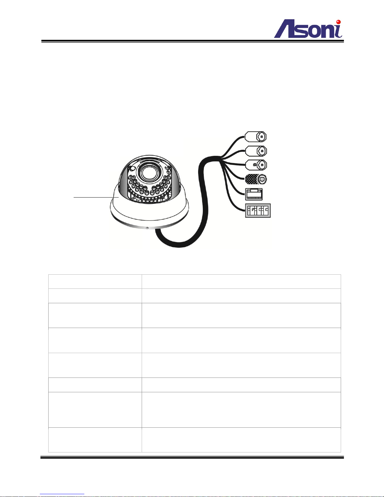
Power Jack:
To connect the DC 12V power adapter.
Network Connector:
The RJ-45 connector allows connect the Ethernet cable.
Video Output:
The BNC connector allows connect to the analog display to
output analog video for locally monitoring.
Microphone Input (Pink)
Allows connect to an external passive-type of microphone, the
audio will be heard at the remote site.
Audio Output (Green):
Allows connect to an amplified speaker, you can hear the
voice of the remote site from the speaker.
Micro-SD Card Slot:
Allows insert a Micro-SD card to be the storage.
USB Port:
The port allows connect to a USB flash to be the storage.
If the camera is wireless model, connect the included USB
wireless dongle into this port.
Terminal Block:
The terminal block provides the foll owing functionalities:
Digital I/O: Digital In and Digital Out.
(Inside)
7
COM – Digital Out common pin.
D_Out – Digital Out pin.
D_IN – Digital In pin.
Factory Default (DEFAULT): To let the camera backs to
factory default.
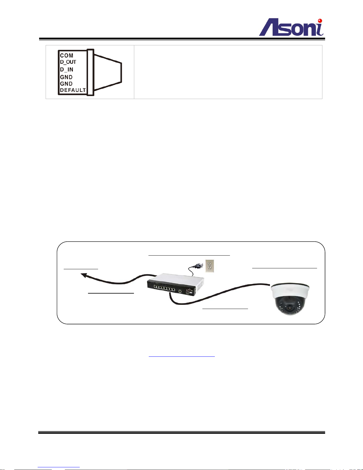
1. Connect the cable of Digital I/O, Audi o output and Audio input if you want to use these
functionalities.
2. Connect Ethernet cable for network connection.
3. Connect power adapter to turn on the camera.
4. If the camera is PoE model, the power adapter is not necessary. The camera will get
the power from the PoE injector or PoE switch.
PoE (Power over Ethernet) is a technology that integrates power into a standard LAN
infrastructure. It enables power to be provided to the network device, such as an IP
phone or a network c amera, usi ng the s ame cable as tha t use d for netw ork c onnect ion .
It eliminates the need for power outlets at the camera locations. Please follow the
below figure for the connection.
5. Set up the network configurations according to the network environment. For further
explanation, please refer to Network Configuration chapter.
6. After finish the configuration for the very first time, if you want to use wireless network,
connect the included USB wireless dongle into the USB port, and then configure the
wireless settings, then, plug out the Ethernet cable to use the wireless connection.
PoE Swi t ch or PoE Injector
Ethernet Cable
Data only
Ethernet Cable
Mixed data and power
PoE Network Camera
To Network
8
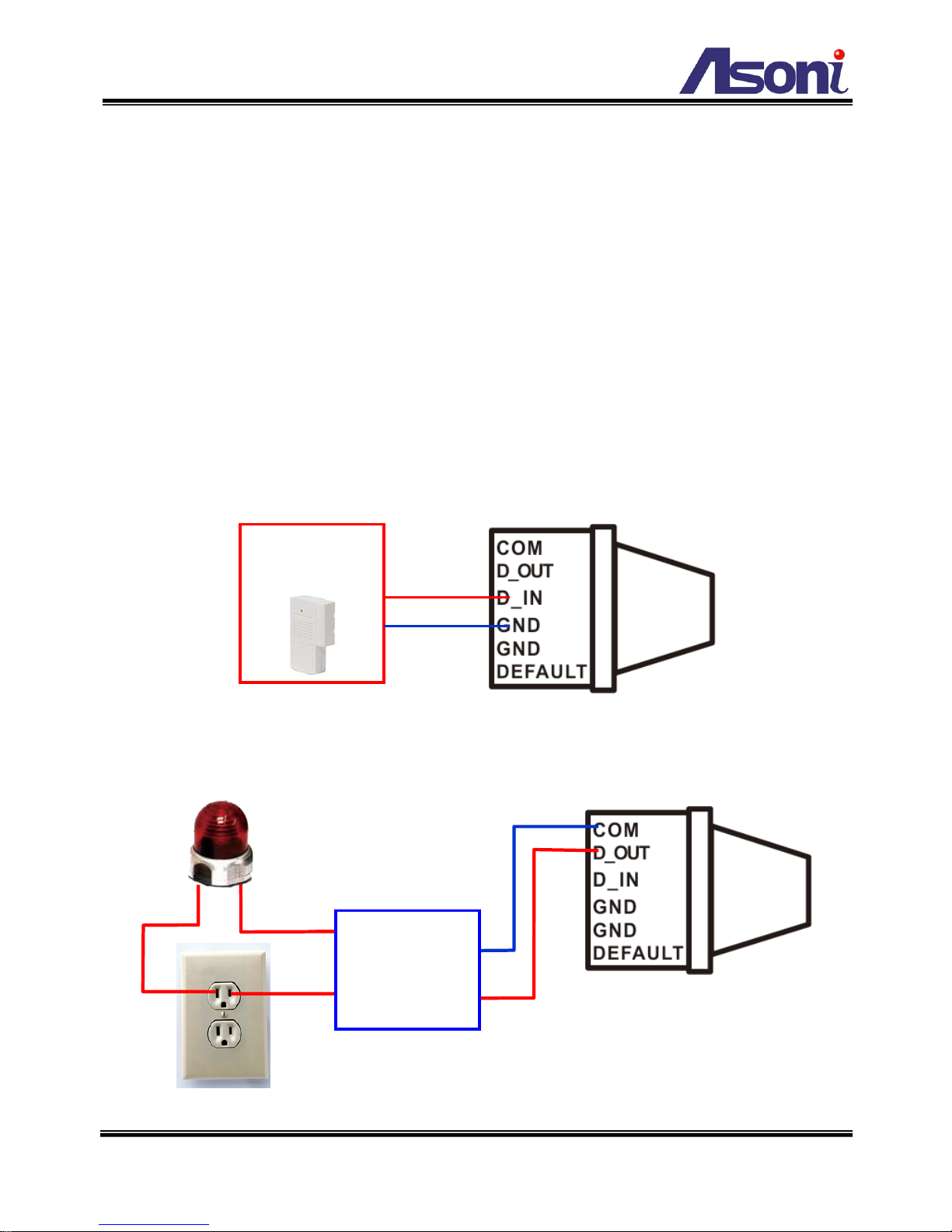
3.1.2 Digital I/O Connections
The terminal block of the camera also provides Digital Input and Digital Output. You can
connect the wires of connector to this terminal block to output these signals. The I/O
connector provides the interface to:
1 set of Digital Input (D_IN + GND) – The digital inputs for connecting devices that
can toggle between an open and closed circuit, such as PIRs, door/window
contacts, glass break detectors, e tc . When a signal is recei ved the status chang es
and the input becomes active.
1 set of Digital Output (D_OUT + COM) – The output to Relay Box or Relay Board,
and switch on the alarm device such as LEDs, Sir ens, etc.
Digital Input (Alarm Input)
Digital Output
Door/Window
Contacts
Relay Board
or
Relay Box
9
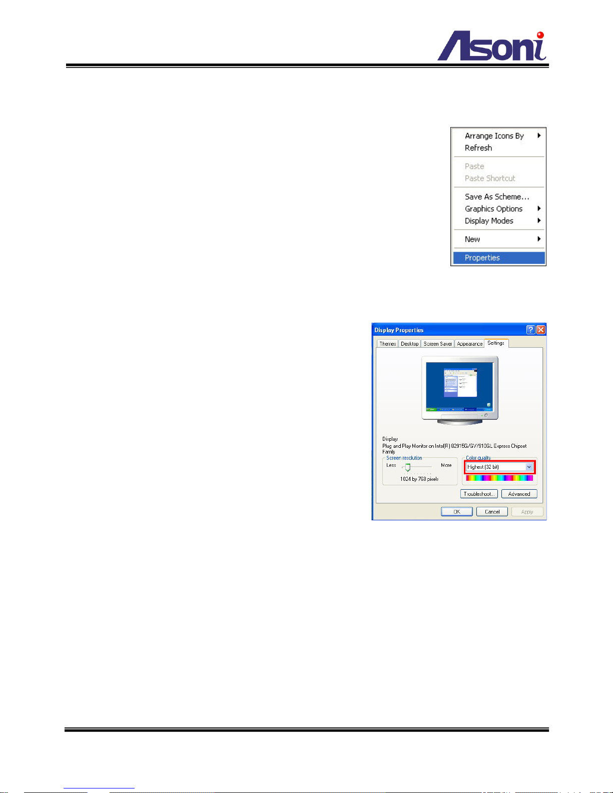
3.2 Monitor Setting
1. Right-Click on the desktop. Select “Properties”
2. Change c ol or quali ty to “Highest (32bit)”.
10
3.3 IP Assignment
Always consult your network administrator before assigning an IP address to your
camera in order to avoid using a previously assigned IP address.
MAC Addres s: Each network camera has a unique Ethernet address (MAC address)
shown on the sticker of the device.
“Asoni IP Search” is a uti lity that prov ides an easier, more efficient way to co nfig ure th e IP
address and network settings of the network camera in Local Network (LAN).
The software can be installed from the attached software CD.
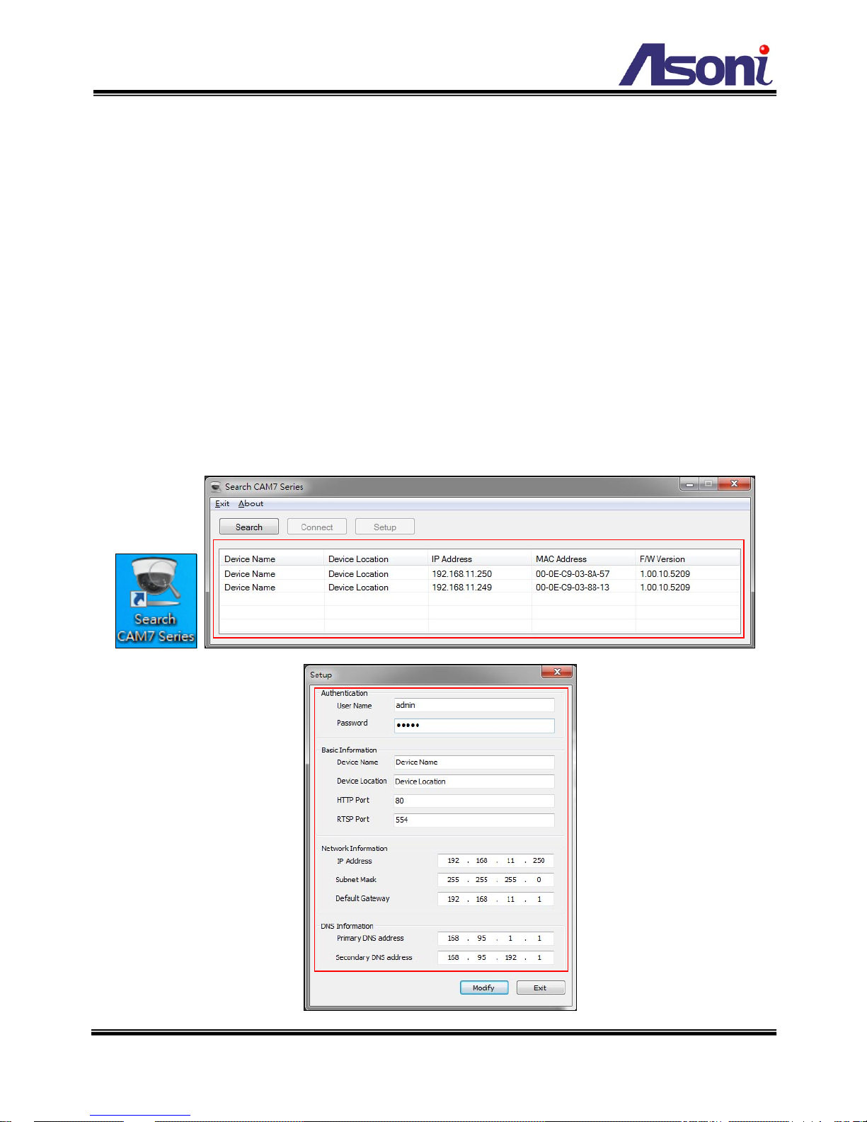
1. Once “Asoni IP Search” has been successfully installed on the computer, double
click the “Search CAM7 Series” icon on the desktop.

11
2. IP Search searches all the network devices which connect to the intranet and lists
on the window. Click [Search] button to search again.
3. From the list, click and select the device with the MAC Address that corresponds to
the device that is to be configured, and then click [Setup] button, the network
configuration of this device will be shown.
4. Input “admin” and “admin” in Username and Passwor d fields, and then filling in the
IP Address, HTTP Port, RTSP Port, Subnet Mask, Gateway and DNS.
5. Click [Modify] button to save the settings into the device.
6. Wait for one minute to let the device update the settings, and then click [Search]
button again to re-search the network devices.
7. If you want to view the device with IE browser, double-click the network device
listed on the window, it will open an IE browser and connect to this device directly.
12
4. Live Video
4.1 Connect with PC
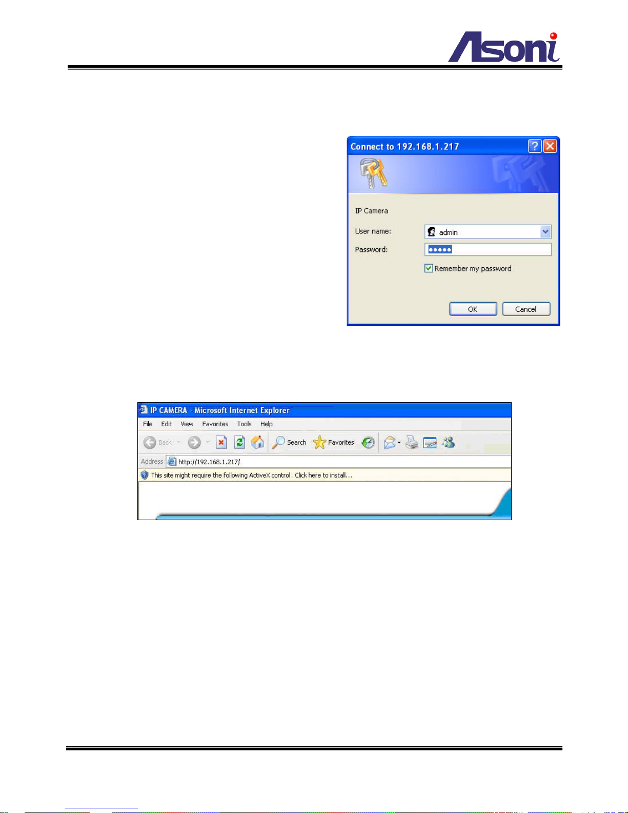
Start the IE browser, type the IP address of the
network camera in the address fi el d:
http://<IP of camera>
If the “HTTP Port” has been changed from “80”,
type the URL as:
http://<IP of camera>:<HTTP Port>
After link to the camera, it will show a dialogue
box. Key-in the user name and password to
log-in and open the web page of camera.
The default user name and password are “admin” and “admin”.
For the first time to view the camera video via IE, it will ask you to install the ActiveX
component.
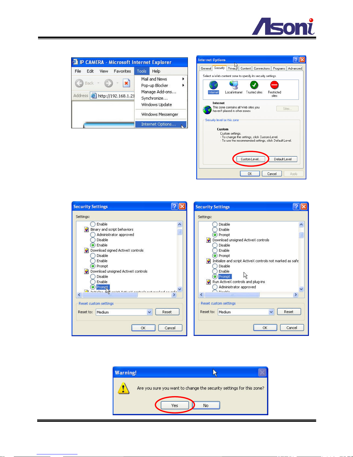
If the installation failed, please check the security setting for the IE browser.
1. If you want to view the device with IE browser, double-click the network device
listed on the window, it will open an IE browser and connect to this device directly.
2. In IE, click on [Tools] [Internet Options…]
3. Click on [Security] Tab [Custom Level…]
4. In Security Settings, under [Download unsigned ActiveX controls], select
“Enable” or “Prompt”.
5. In Security Settings, under [Initialize and script ActiveX controls not marked as
safe], select “Enable” or “Prompt”.
6. When pop-up window with warning message, click [Yes] to save the settings.
13
1
2
3
4
5
When popup the following dialogue box, click [Yes].
14
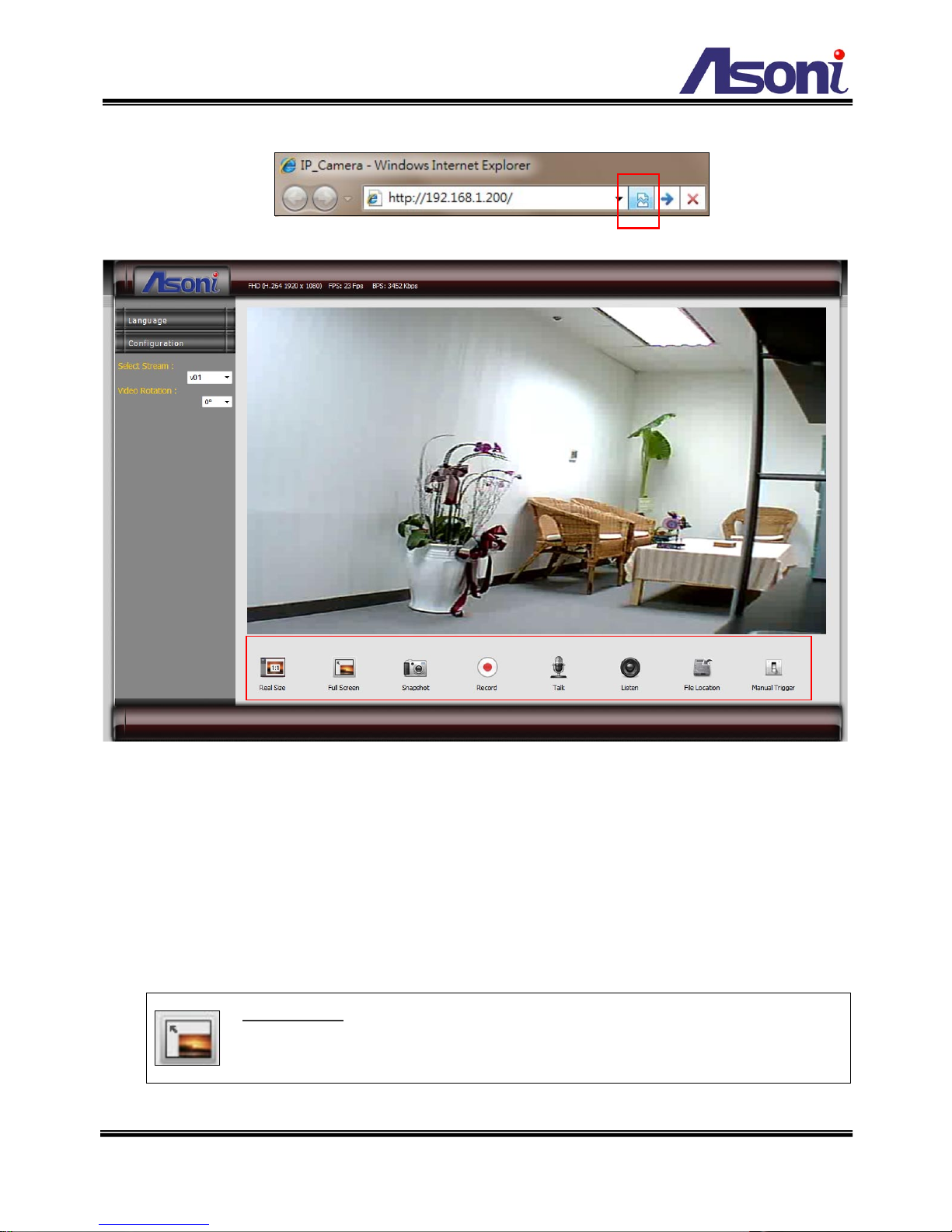
The web page of the device shows as following.
Language : Change the display language.
Configuration : Go into the configuration page to set the parameters if necessary.
Select Stream : Select the video stream from the pull-down list to display it.
Video Rotation : Select the orientation from the pull-down list to display the video.
Status Bar : Shows video resolution, video refresh rate (FPS) and video bit rate.
Function Buttons : Click these buttons will perform the following functions.
Full Screen : Click this button, the video will change to full screen mode.
Press [Esc] key or double-click the video again, it will back to normal mode.
⑥
⑤③②
①
④
15
Snapshot : Click this button to take snapshot of the video. The image will be
saved to the indicated location that is defined with [File Location] button.
Record : Click this button to record the video into the local PC. The video will
be saved to the indicated location that is defined with [File Location] button.
To stop recording, click this button again.
The saved video format is AVI. The recorded file can be played by Microsoft
Media Player. Note, H.264
decoder must be inst al l e d to pl ay the recorded file.
You can install “FFdshow” from the included CD for the decoder.
Talk : The camera supports 2-way audio. Click this button, then you can use
microphone which connected to the PC to talk to the camera side.
Listen : Click this button to listen
the audio from camera. Click again to t ur n off
it.
File Location : Sets the location where the video and snapshot are saved to.
The default location is “C:\”. To change the location, click this button and select
the desired location.
Manual Trigger : Click the button to manually trigg er an ev ent when requi red.
Note: an Event shoul d be s et be fore t his featu re c an be us ed. R efer on h ow t o
setup an Event in Configuration Event Handling Configuration.

16
4.2 Connect with Mobile Phone
Start the web browser , type the IP addr es s o f the network camera in the address field:
http://<IP of camera>
After link to the camera, it will show a dialogue box for log in. Key-in the user name and
password to log-in and the live video will be shown.
The default user name and password are “admin” and “admin”.
If the above URL can’t see the live video, try to type the below URL:
http://<IP of camera>/viewer/mobile_view.html
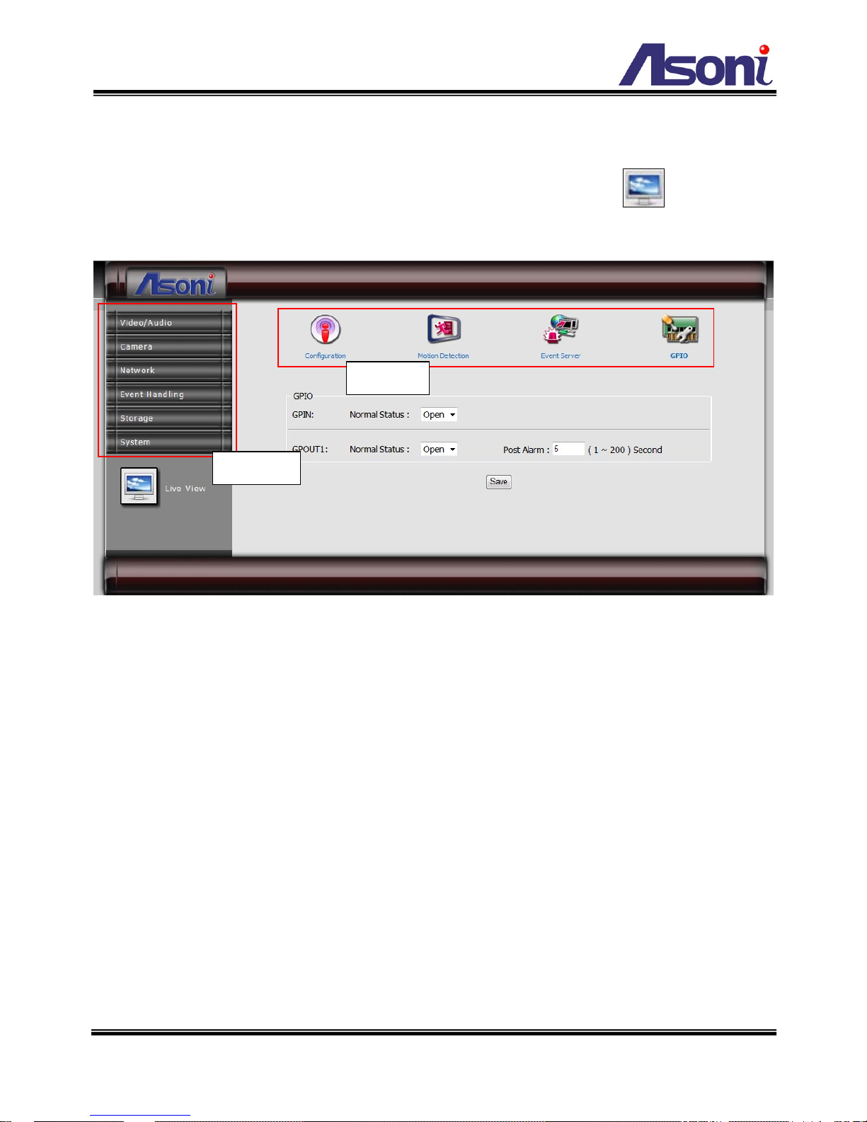
17
5. Configuration
Click [Configuration] button to get into the configuration page. Click [Live View]
button to back to the Live-View page.
To open the page for configure, click the button on “Mai n me nu” area on the left side, and
then click the button on “Sub-menu” on the top side. Refer to the related chapter to
configure the camera.
Main menu
Sub-menu
18
5.1 Video / Audio
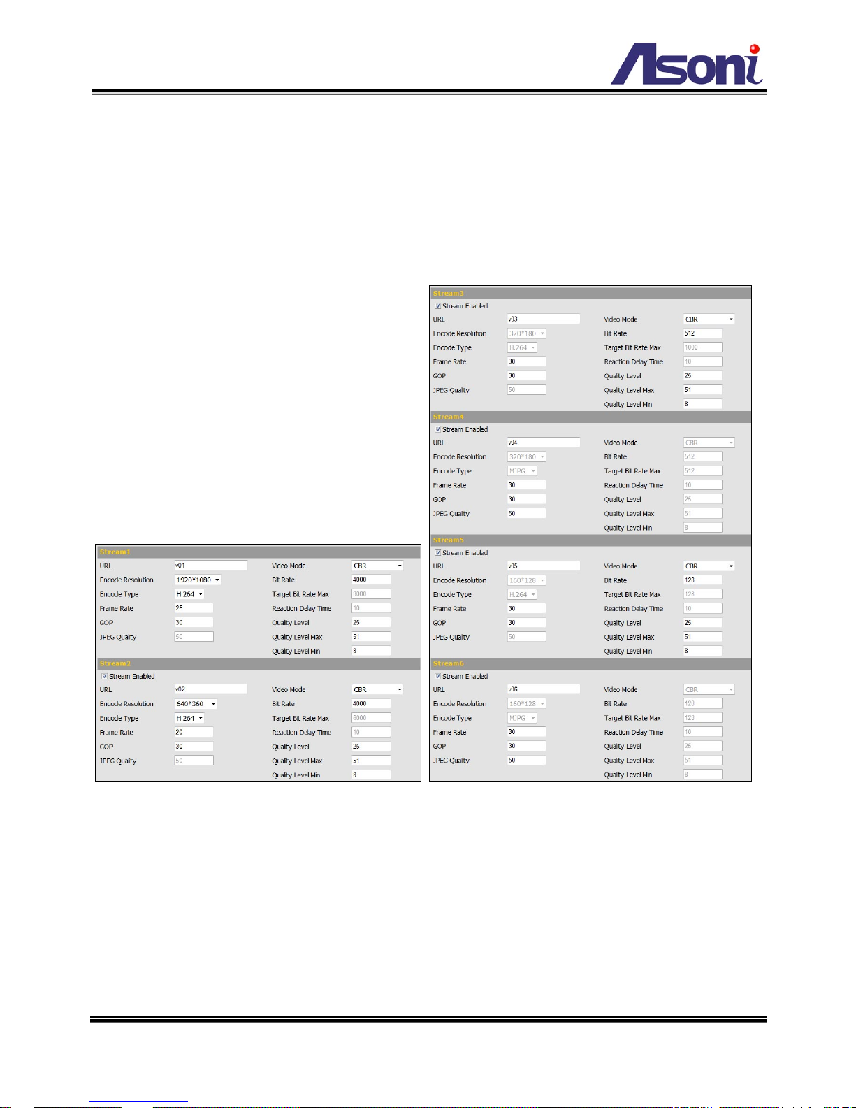
5.1.1 Video Stream
This device has in total 6 independent and simultaneous streams which can be used. The
Live View page provides access to a list of streams which are set in this page.
Stream Enabled
Stream 2 ~ 6 can be enable or disable by check or uncheck this option.
URL
Sets the name for the video stream; input an appropr i ate name to indicate the stream
type which is being used. The name will be listed in the Live View page for choose.
If you want to get the video stream through RTSP protocol, include the name in the
path, i.e. “rtsp://<Camera IP>/v01”.
 Loading...