

Page 1
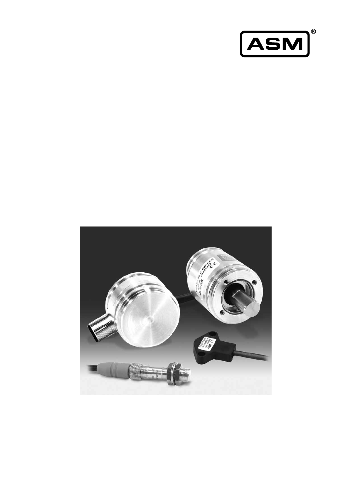
POSIROT
®
/ PRAS
Analog Magnetic
Angle Sensors
Instruction Manual
Please read carefully before installation and operation!
Page 2

POSIROT
Contents
®
Contents
Safety instructions 3
Intended use 4
Unintended use 4
Description 5
Mounting 5
Placement and alignment of the position magnet 5
Reference position 7
Torque for the mounting screws 8
Electrical installation 8
Sensor fixing with shield 9
Outline drawings 10
Specification of the outputs 25
Signal wiring 28
Accessories 31
Accessory cables 31
Position magnets 33
Mounting plates 38
Couplings 40
Service, calibartion, disposal 41
Reliability characteristics 42
Declaration of conformity 43
2 MAN-PRAS-E-15 ASM GmbH
www.asm-sensor.com
Page 3
POSIROT
®
Instruction Manual
Safety
instructions
Explanation of used
safety signs and
signal words
Do not use POSIROT® position sensors in safety critical applications where malfunction or total failure of the sensor may
cause danger for man or machine.
For safety related applications additional mechanisms (devices) are necessary to maintain safety and to avoid damage.
Disregard of this advice releases the manufacturer from product liability.
The sensor must be operated only within values specied in
the catalog or datasheet.
Connection to power supply must be performed in accordance
with safety instructions for electrical facilities and performed
only by trained staff.
WARNING, Risk of Injury:
Indicates a potentially hazardous situation, which,
if not avoided, could result in serious injury or
property damage.
DANGER
WARNING
CAUTION
NOTICE
WARNING, Risk of Personal Injury or Death:
Indicates a situation that can result in serious personal
injury or death if not properly avoided.
WARNING, Risk of Personal Injury or Death:
Indicates a situation that can result in moderate
personal injury or death if not properly avoided.
WARNING, Risk of Personal Injury:
Indicates a situation that can result in minor personal
injury if not properly avoided.
WARNING, Risk of Property Damage:
Indicates a situation that can result in minor to major
property damage if not properly avoided.
ASM GmbH MAN-PRAS-E-15 3
www.asm-sensor.com
Page 4
POSIROT
®
Instruction Manual
Intended use
Unintended use
Maintenance and
service
Maintenanceinterval
The angle sensor was intended for angular position measurement,
when properly mounted and used in the properly rated ambient
atmospheric and technical conditions for which the sensor is
designated.
Theunintendeduseiswhenthesensorisusedoutsideitsspecied
technical and ambient atmospheric conditions or when improperly
mounted.
• In order to avoid risk of injury and improper handling the
customer is not allowed to repair the sensor. No warranty or
liability will be granted for opened sensors.
• Damaged sensors must be shut down immediately and sent
to the factory for repair.
Proper maintenance comprises the visual examination of parts (e.g.
integrity of housing, connectors and cables). Maintenance intervals
dependonthespecicapplicationandshouldbedenedbytheuser
in dependance of operating conditions.
The following maintenance steps are recommended:
PRAS2
PRAS3
PRAS5
PRAS5-V
PRMAG20
PRMAG21
PRMAG22
PRMAG5Z
Maßnahmen
Deinstallation
Integrity of housing,
connector, cable
X X
X X X
X X
X X X
Damaged parts: Put
sensor out of service and
replace damaged parts
resp. send sensor to ASM
for repair
Loose mounting parts:
Screw tight mounting parts
with recommended torque,
if applicable use bolt
adhesive
Mounting
elements
X
X
X
X
Disconnectelectricalconnections.Loosenxingscrews.
Visual check of
shaft sealing
Damaged shaft sealing:
Put sensor out of service
and send it to ASM for
repair
Disposal
4 MAN-PRAS-E-15 ASM GmbH
www.asm-sensor.com
Disposal according to applicable government regulations.
Page 5
POSIROT
®
Instruction Manual
Description
Mounting
The angle sensors PRAS of the POSIROT® product family perform touchless or shaft based angle measurement. A position magnet rotates in front
of the sensing area of the sensor head. The angular position is converted
into a standardized high resolution voltage or current output. Measuring
ranges 15° to 360° having rising or falling characteristic are available.
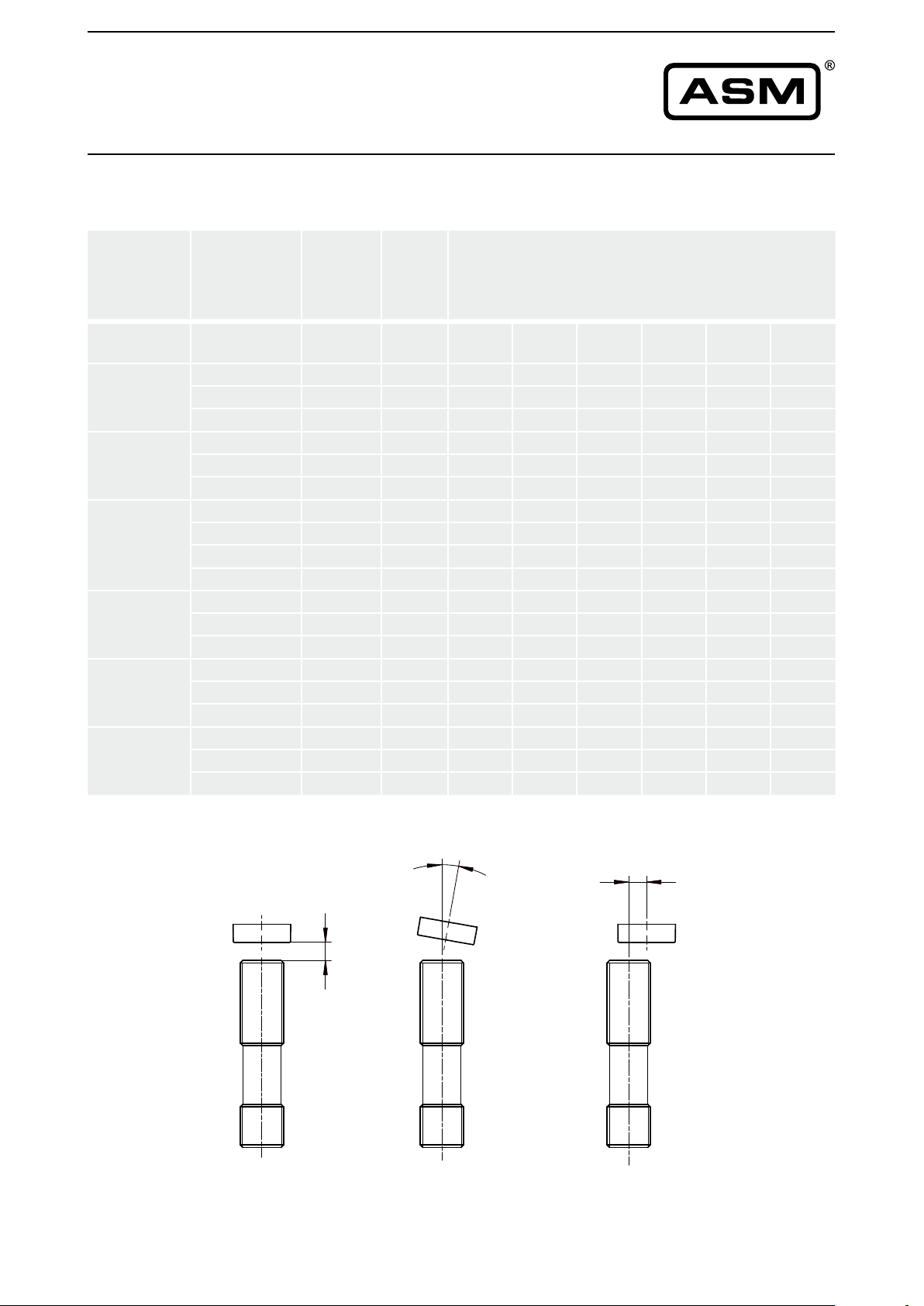
Placement and alignment of the position magnet
NOTICE
For non-contact sensor models air gap and alignment of sensor and
position magnet has to be observed. The linearity will degrade in case of
misalignment.
Adjacent magnetic elds or ferromagnetic materials can inuence the
measurement results of the PRAS sensors of the POSIROT
family. Therefore the angle sensors should be mounted solely with
nonmagnetic / non magnetisable shields and screws.
The angle sensors PRAS2, PRAS3 and PRAS5 are equipped with
an integrated magnetic shield which minimizes the sensitivity against
externalmagneticelds.
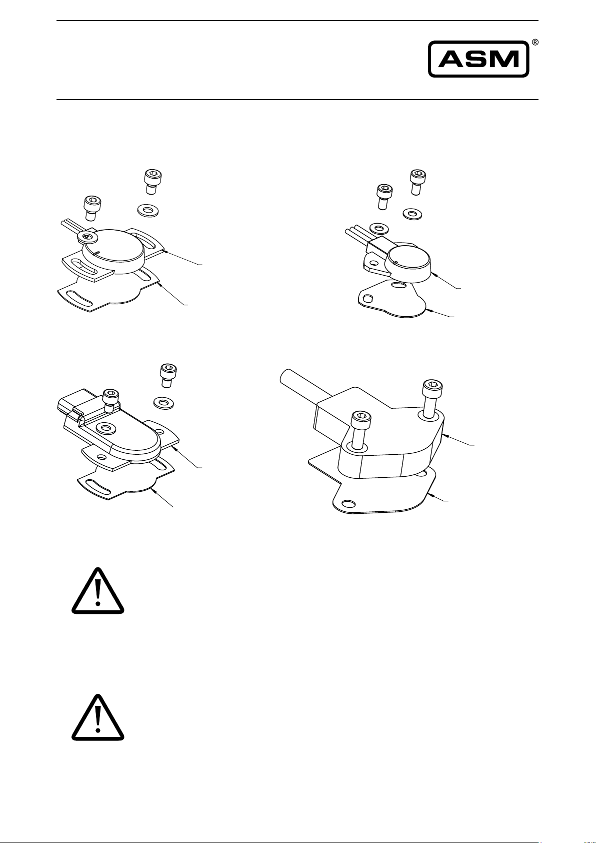
Optional shield plates are available for the angle sensors PRAS20,
PRAS21, PRAS26 and PRAS27. They can reduce the effect of residual
magnetizing in case the sensor has to be mounted on a ferromagnetic
material (see page 9). It is however not possible to exclude the effect of
lateralexternalmagneticelds.
®
product
ASM GmbH MAN-PRAS-E-15 5
www.asm-sensor.com
Page 6
c
POSIROT
®
Instruction Manual
Mounting
(continued)
Sensor
PRAS1
PRAS2
PRAS5
PRAS20
PRAS26
PRAS21
PRAS27
Measuring error by misalignment of the position magnet
Air gap
Position
magnet
PRMAG20 0 ... 6.5 0 ... 5 0.15 0.4 0.8 2.2 5.0 –
PRMAG21 0 ... 4 0 ... 5 0.2 0.4 1.0 3.8 10 –
PRMAG22 0 ... 9.5 0 ... 5 0.1 0.4 1.0 2.2 4.5 8.0
PRMAG20 0 ... 6 0 ... 5 0.15 0.4 0.8 2.2 5.0 –
PRMAG21 0 ... 3.5 0 ... 5 0.2 0.4 1.0 3.8 10 –
PRMAG22 0 ... 9.0 0 ... 5 0.1 0.4 1.0 2.2 4.5 8.0
PRMAG5-Z 0 ... 7.5 0 ... 5 0.1 0.2 0.6 1.5 4.5 8.5
PRMAG20 0 ... 5.5 0 ... 5 0.15 0.4 0.8 2.2 5.0 –
PRMAG21 0 ... 3 0 ... 5 0.2 0.4 1.0 3.8 10 –
PRMAG22 0 ... 8.5 0 ... 5 0.1 0.4 1.0 2.2 4.5 8.0
PRMAG20 0 ... 7 0 ... 5 0.1 0.3 0.7 2.0 4.6 –
PRMAG21 0 ... 2 0 ... 5 0.15 0.3 0.9 3.6 9.6 –
PRMAG22 0 ... 10 0 ... 5 0.0 0.0 0.7 1.5 3.8 7.0
PRMAG20 0 ... 7.0 0 ... 5 0.1 0.3 0.7 2.0 4.6 –
PRMAG21 0 ... 2 0 ... 5 0.15 0.3 0.9 3.6 9.6 –
PRMAG22 0 ... 10 0 ... 5 0.0 0.0 0.7 1.5 3.8 7.0
PRMAG20 0 ... 7.5 0 ... 5 0.1 0.3 0.7 2.0 4.6 –
PRMAG21 0 ... 2.5 0 ... 5 0.15 0.3 0.9 3.6 9.6 –
PRMAG22 0 ... 10.5 0 ... 5 0.0 0.0 0.7 1.5 3.8 7.0
[mm]
(a)
Parallelism
[°]
(b)
0.2
mm
Error by axial misalignment
[°]
(c)
0.5
mm
1 mm 2 mm 3 mm 4 mm
b
c
a
6 MAN-PRAS-E-15 ASM GmbH
www.asm-sensor.com
Page 7
POSIROT
®
Instruction Manual
Mounting
(continued)
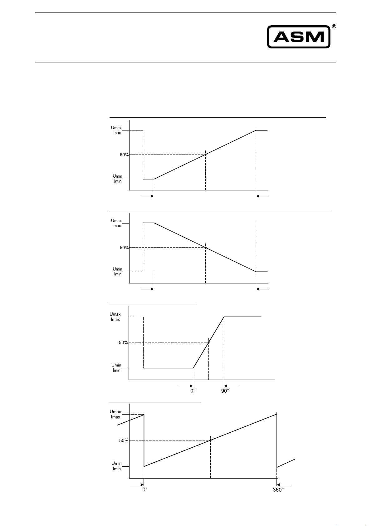
Reference position
For ease of mounting there are reference markings at housing, position
magnet and near the shaft. If both markings match output will be on the
50% of full scale.
Clockwise increasing signal (CW), view to sensor measuring area/shaft
Marking
Range [°]
Counterclockwise increasing signal (CCW), view to sensor measuring area/shaft
Example for angle range 90°
Example for angle range 360°
Marking
Range [°]
Marking
Marking
ASM GmbH MAN-PRAS-E-15 7
www.asm-sensor.com
Page 8
POSIROT® /
Instruction Manual
Mounting
(continued)
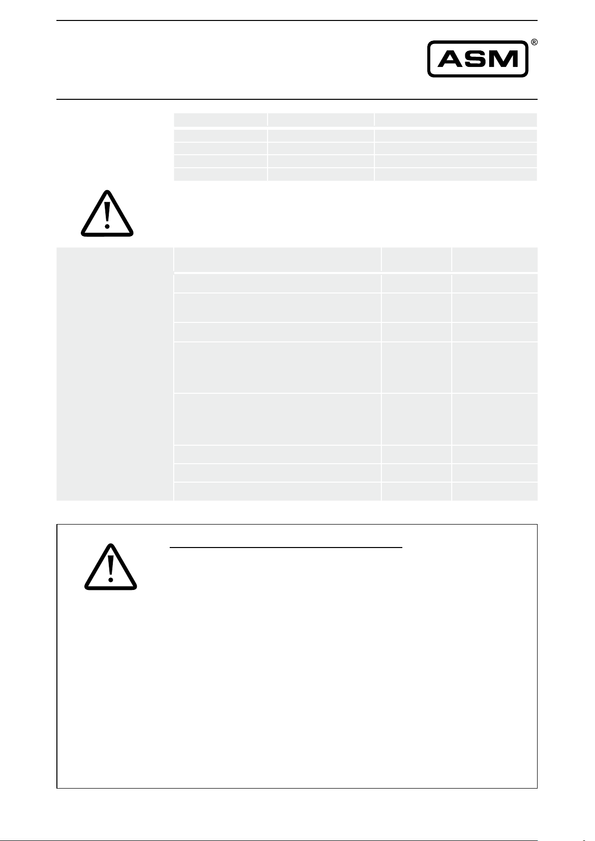
Torque
Output Value range 50% value of output signal
U2 0.5 ... 10 V 5.25 V
U6 0.5 ... 4.5 V 2.5 V
U8 0.5 ... 4.5 V 2.5 V
I1 4 ... 20 mA 12 mA
Torque for xing screws
Thespeciedtorquesandmountingmethodsaregeneralrecomendations
and can differ according to application and operating conditions.
Mounting method Material Torque
[Nm]
Nuts M12x1 (PRAS1) – 2.5
M2,5 screws for mounting brackets (PRAS2,
PRAS3)
M3screwsformountingange(PRAS3) – 1.2
M3 screws with washer (PRAS21) A4
M4 screws with washer (PRAS20) A4
– 0.8
Aluminium
Brass
Plastic
Aluminium
Brass
Plastic
<0.8
–
–
–
<1.8
–
–
–
NOTICE
M4 screws (PRAS27) – 1
M4 screws with washer (PRAS26) A2 <1.8
M8 screws (PRAS5) – < 10
Electrical installation
Supply voltage, current consumption, wiring
For wiring of connector or cable outlet as well as supply voltage and current
consumptionrefertochapter„Specicationoftheoutputs“attheendofthis
manual.
Cable screen has to be connected to protective earth.
Caution: Observe different color code for pre-assembled accessory cables
- refer to accessories pages.
The protection class of sensors with connector output is valid only if the
electrical plug is connected!
Caution: Do not twist the M12 connector insert.
Cable outputs must be installed in such a way that no moisture can get into
the cable.
Crossing the dew point must be avoided.
Do not strain the connection cable.
A separate cord grip is recommended.
8 MAN-PRAS-E-15 ASM GmbH
www.asm-sensor.com
Page 9
POSIROT
®
Instruction Manual
Mounting
Sensor xing with a shield plate (optional)
(continued)
PRAS20 PRAS21
PRAS20
shield plate
PRAS20-MSHIELD
PRAS26
PRAS27
PRAS21
shield plate
PRAS21-MSHIELD
NOTICE
PRAS27
PRAS26
shield plate
PRAS20-MSHIELD
shield plate
PRAS27-MSHIELD
Mechanical information PRAS3, PRAS5-V
• Prevent the sensor shaft from binding.
• Useshaftcouplingsresp.torquearms(e.g.exibleones)toavoid
misalignment errors.
(see chapter „couplings“)
Mechanical information PRAS20, PRAS21, PRAS26, PRAS27
• Mountthesensoronaatsurface.
• Do not deform the sensor housing!
NOTICE
ASM GmbH MAN-PRAS-E-15 9
www.asm-sensor.com
Page 10
POSIROT
®
Instruction Manual
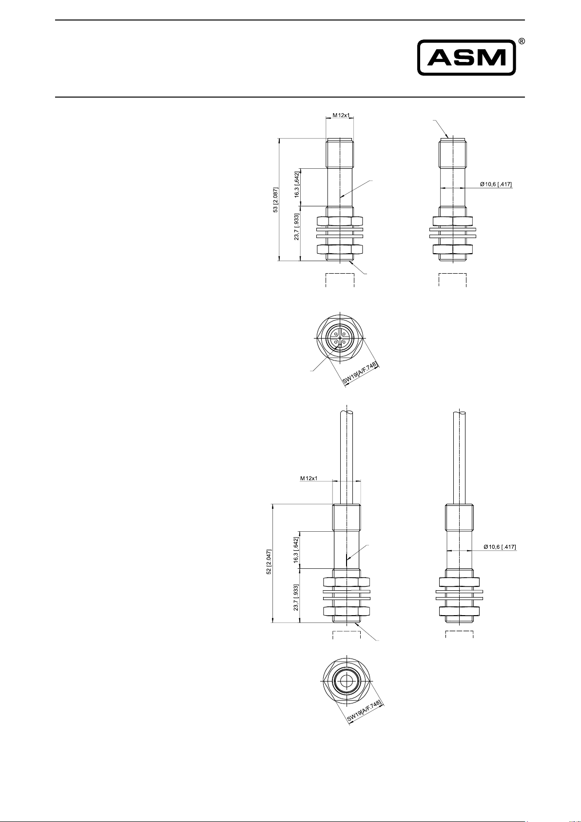
Outline drawing
PRAS1
Connector version
Marking
M12 connector
Marking
Measuring area
Position
magnet
Dimensions in mm [inch]
Outline drawing
PRAS1
Cable version
Marking
Measuring area
Position
magnet
Dimensions in mm [inch]
Weight without cable 20 g approx.
Dimensions informative only.
For guaranteed dimensions consult factory.
10 MAN-PRAS-E-15 ASM GmbH
www.asm-sensor.com
Page 11
kierung
ng
POSIROT
®
Instruction Manual
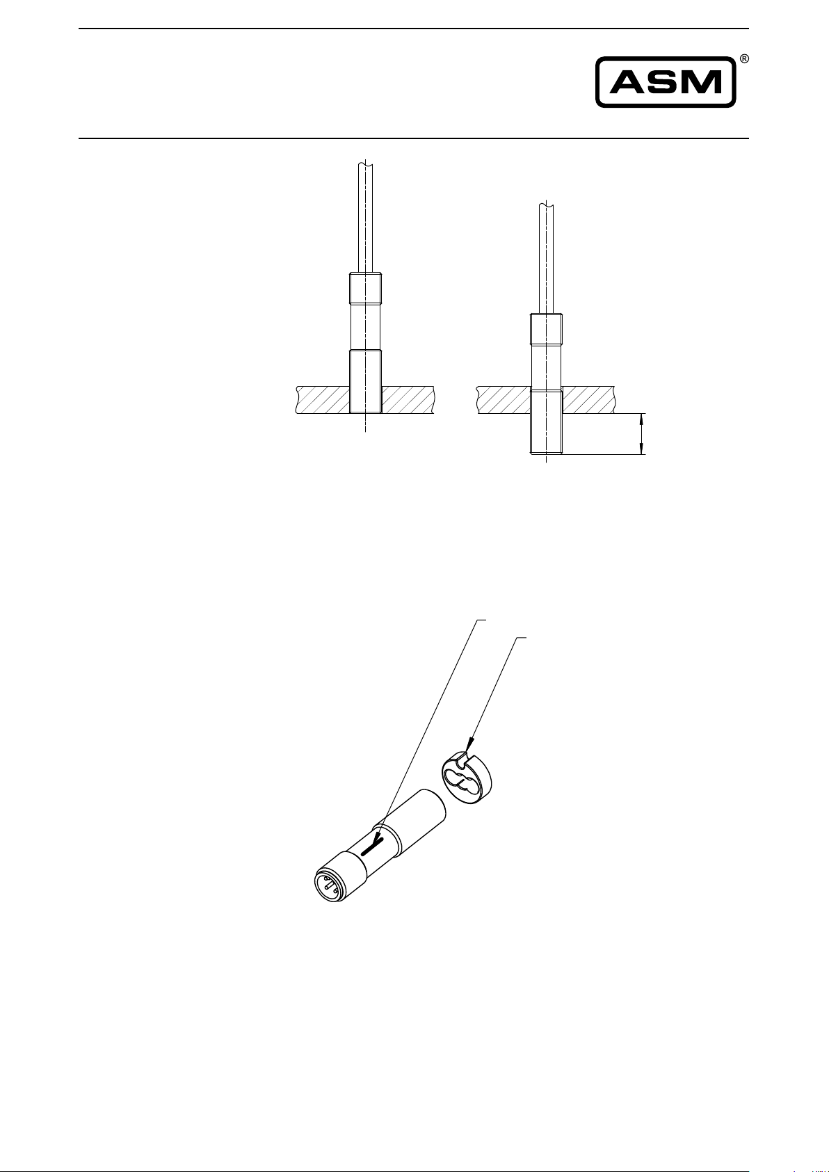
Mounting PRAS1
5
1
>
Reference
position
(see page 7)
Flush-mounted
bündig
nicht magnetisches Material
Non-magnetic material
In case of
nicht bündig
magnetic material
magnetisches Material
Markieru
Marking
Mar
Marking
ASM GmbH MAN-PRAS-E-15 11
www.asm-sensor.com
Page 12
rkierung
ung
POSIROT
®
Instruction Manual
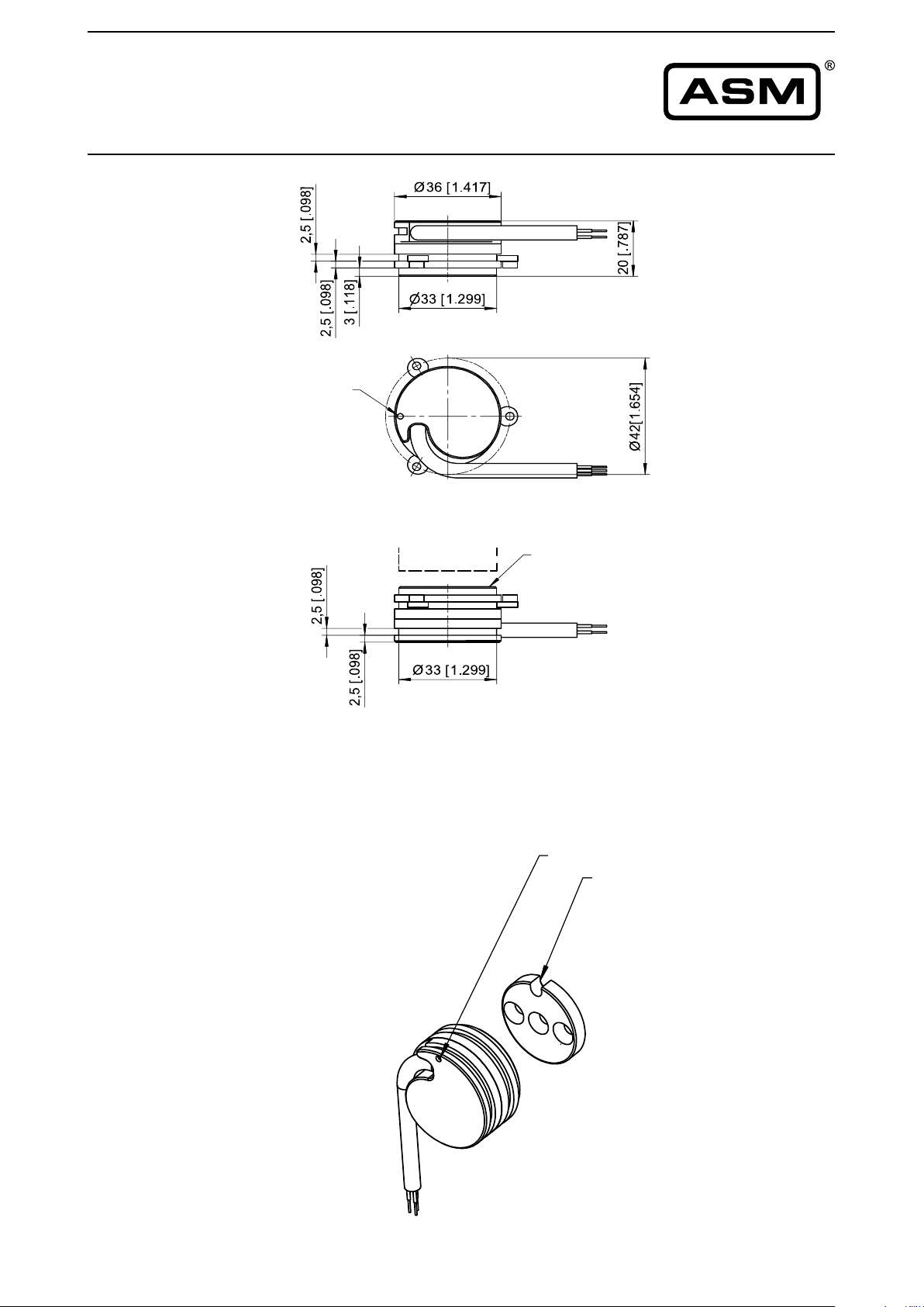
Outline drawing
PRAS2
Cable version
Marking
Reference
position
(see page 7)
Position
magnet
Weight without cable 40 g approx.
Dimensions informative only.
For guaranteed dimensions consult factory.
Measuring area
Dimensions in mm [inch]
Markier
Marking
Ma
Marking
12 MAN-PRAS-E-15 ASM GmbH
www.asm-sensor.com
Page 13
POSIROT
®
Instruction Manual
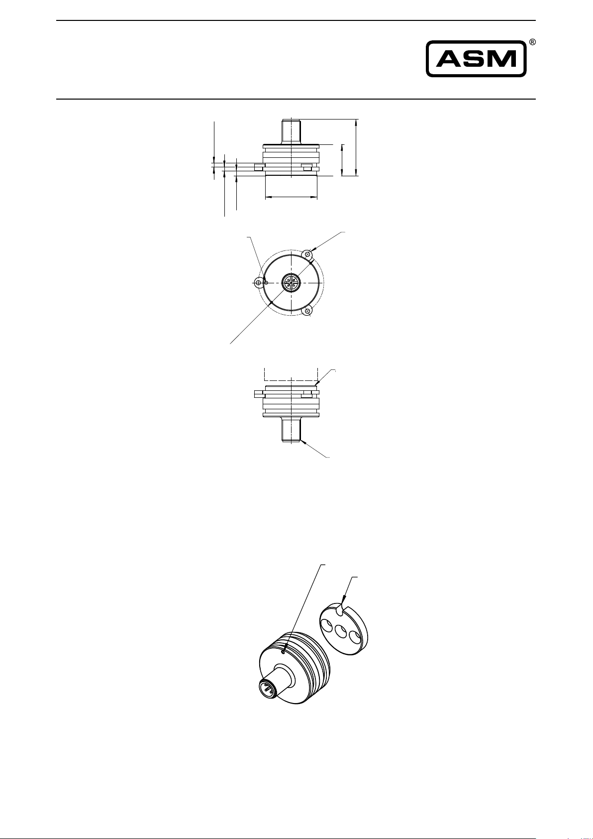
Outline drawing
PRAS2
Connector version
M12 axial
]
8
9
.0
0
[
5
,
2
]
]
8
8
1
9
.1
.0
0
0
[
[
3
,5
2
Marking
Markierung
2
4
]
7
1
]
.4
7
1
8
[
7
.
6
0
3
[
0
2
33 [1.299]
Befestigungexzenter
Mounting clamps
PRPT-BFS1
PRPT-BFS1
]
4
5
6
.
1
[
Positions-
Position
magnet
magnet
Dimensions in mm [inch]
Measuring area
Messfläche
Reference
position
(see page 7)
M12 Stecker
Connector M12
Weight without cable 50 g approx.
Dimensions informative only.
For guaranteed dimensions consult factory.
Marking
Markierung
Marking
Markierung
Also for connector version
ASM GmbH MAN-PRAS-E-15 13
www.asm-sensor.com
Page 14
POSIROT
®
Instruction Manual
Outline drawing
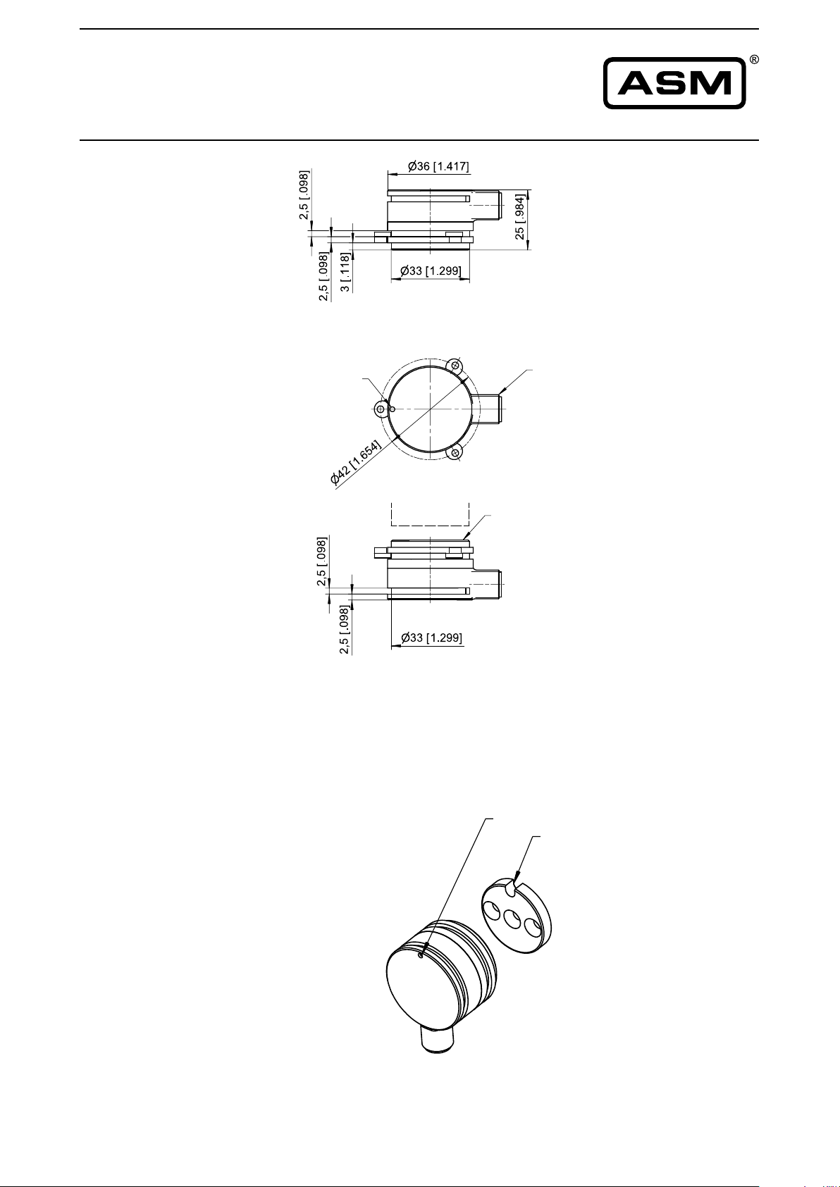
PRAS2
Connector version
M12 radial
Marking
Position
magnet
Weight without cable 50 g approx.
Dimensions informative only.
For guaranteed dimensions consult factory.
Measuring area
Connector M12
Dimensions in mm [inch]
Marking
Markierung
Marking
Markierung
Reference
position
(see page 7)
14 MAN-PRAS-E-15 ASM GmbH
www.asm-sensor.com
Page 15
POSIROT
®
Instruction Manual
Outline drawing
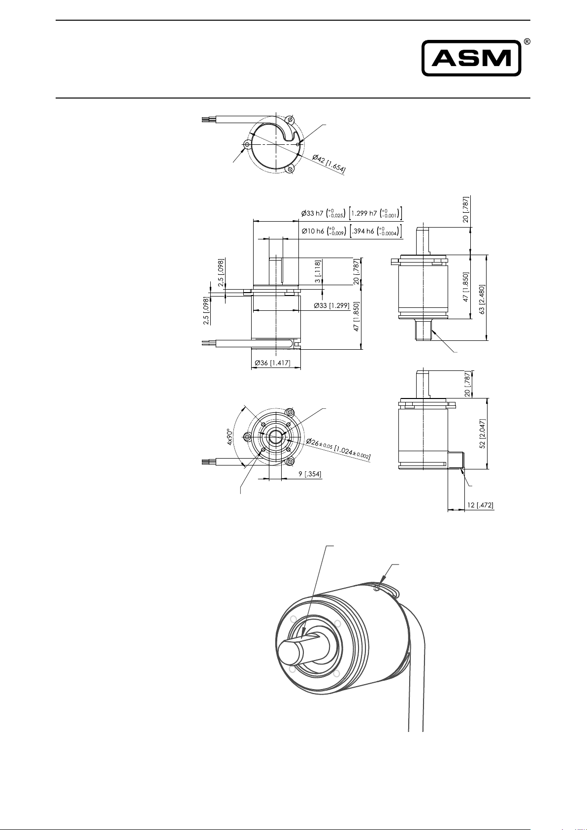
PRAS3
Shaft
dimensions in mm [inch]marking
Mounting clamps
M12 connector
4x M3-5[.197] deep
screw hole orientation to marking not defined!
Reference
position
(see page 7)
Weight without cable 250 g approx.
Dimensions informative only.
For guaranteed dimensions consult factory.
M12 connector
marking
marking
(back site)
ASM GmbH MAN-PRAS-E-15 15
www.asm-sensor.com
Page 16
POSIROT
®
Instruction Manual
Outline drawing
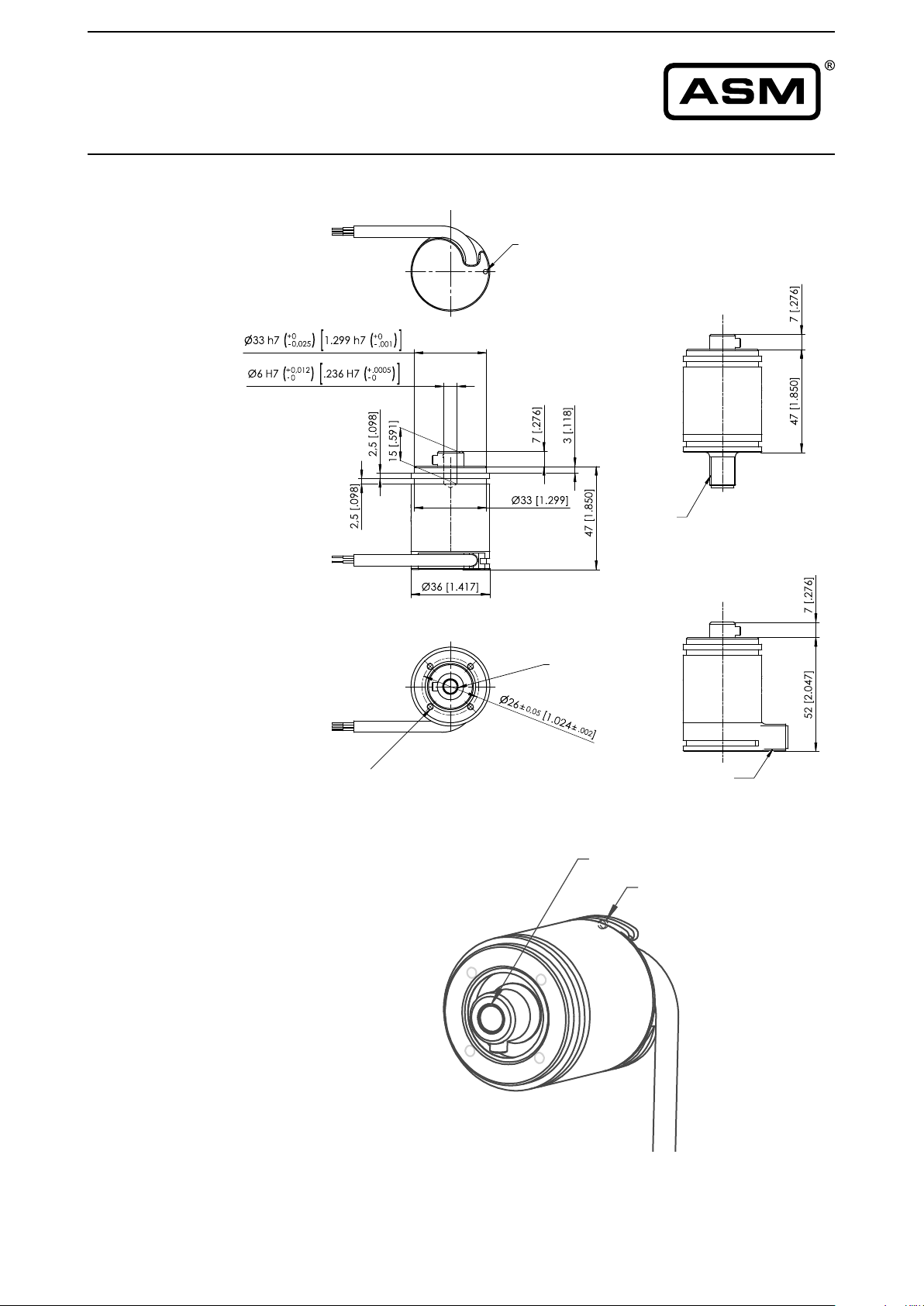
PRAS3
Hollow shaft
marking
M12
connector
4x M3-5[.197] deep
screw hole orientation to marking not defined!
Reference
position
(see page 7)
Weight without cable 250 g approx.
Dimensions informative only.
For guaranteed dimensions consult factory.
Marking
M12
connector
Marking
Marking
(back side)
16 MAN-PRAS-E-15 ASM GmbH
www.asm-sensor.com
Page 17
POSIROT
®
Instruction Manual
Outline drawing
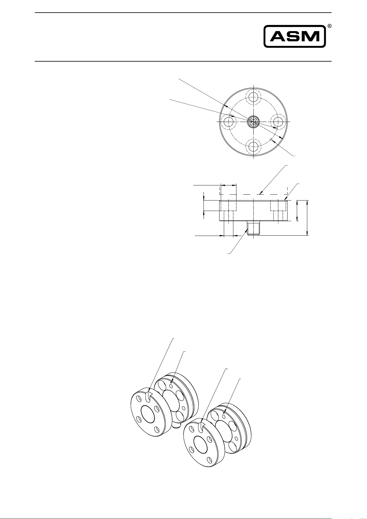
PRAS5
Connector M12
axial
6
+
6
0
-
0
,
1
[
2
.
5
9
+
8
0
-
.0
0
4
8
0
,
0
5
[
1
.
8
15 [.591]
4
]
9
0
.
0
0
2
]
Marking
Markierung
Position magnet
Positionsmagnet
Measuring area
Meßfläche
]
4
9
3
.
[
0
1
9 [.354]Ø
]
7
8
]
7
9
.
3
[
3
.
0
1
2
[
4
3
Reference
position
(see page 7)
Connector M12
M12-Stecker
Dimensions informative only.
For guaranteed dimensions consult factory.
Markierung
Marking
Markierung
Marking
Markierung
Marking
Dimensions in mm [inch]
Marking
Markierung
ASM GmbH MAN-PRAS-E-15 17
www.asm-sensor.com
Page 18
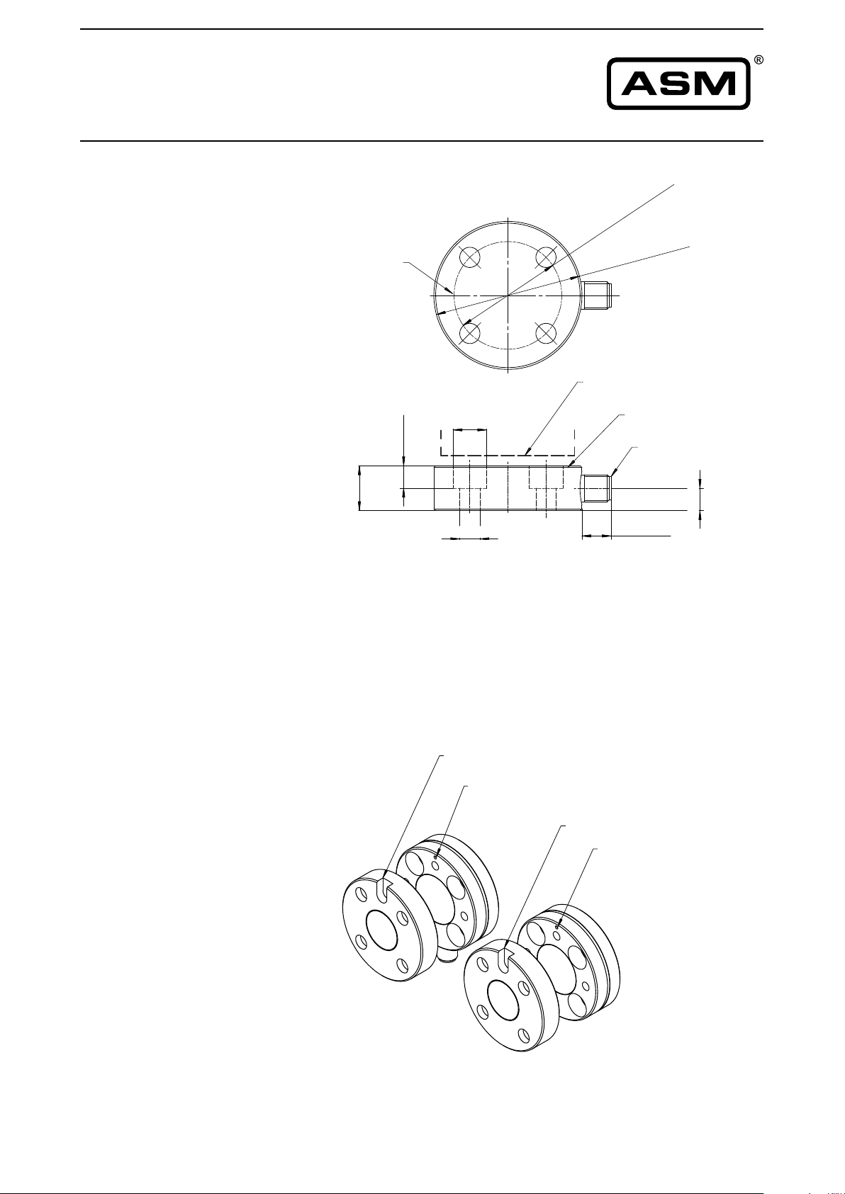
POSIROT
®
Instruction Manual
Outline drawing
PRAS5
Connector M12
radial
Markierung
Marking
]
7
8
7
.
[
0
2
]
2
0
0
.
0
9
8
.
1
[
5
0
,
0
8
4
0
+
,1
0
-
6
6
Position magnet
Positionsmagnet
]
4
9
3
.
[
0
1
15 [.591]Ø
9 [.354]Ø
0
+
]
4
0
0
.
-
8
9
5
.
2
[
Measuring area
Meßfläche
Connector M12
M12-Stecker
13 [.512]
]
4
9
3
.
[
0
1
Reference
position
(see page 7)
Dimensions informative only.
For guaranteed dimensions consult factory.
Marking
Markierung
Marking
Markierung
Markierung
Marking
Dimensions in mm [inch]
Markierung
Marking
18 MAN-PRAS-E-15 ASM GmbH
www.asm-sensor.com
Page 19
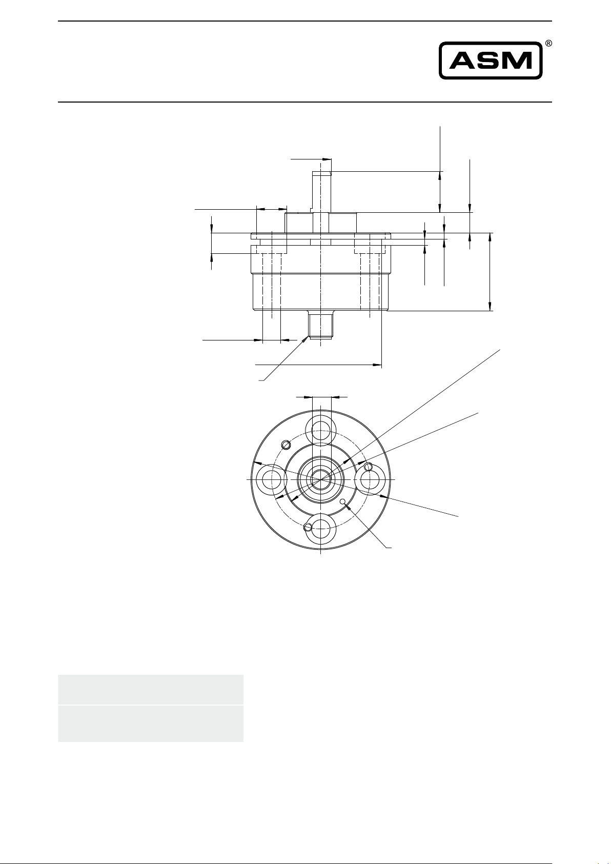
POSIROT
®
Instruction Manual
Outline drawing
PRAS5-V
Connector M12
axial
15 [.591]Ø
]
4
9
3
.
[
0
1
Ø9 [.354]
M12-Stecker
10 [.394]
Ø60 [2.362]
9 [.354]
]
7
8
.7
[
0
]
2
4
9
3
.
[
0
1
]
]
8
8
1
1
.1
.1
[
[
3
3
7
1
4
.
1
[
3
)
,0
4
0
-
0
,
0
-
(
6
f
6
3
48
5
0
,
0
90
.8
1
[
]
6
9
.4
1
[
8
3
]
)
1
0
6
0
.
1
-
0
0
.
-
(
6
f
]
2
0
0
.
Allowable shaft load
(10 mm shaft)
100 N radial, 100 N axial
68
,
2
[
2
.
6
8
5]
Markierung
Dimensions in mm [inch]
Dimensions informative only.
For guaranteed dimensions consult factory.
ASM GmbH MAN-PRAS-E-15 19
www.asm-sensor.com
Page 20
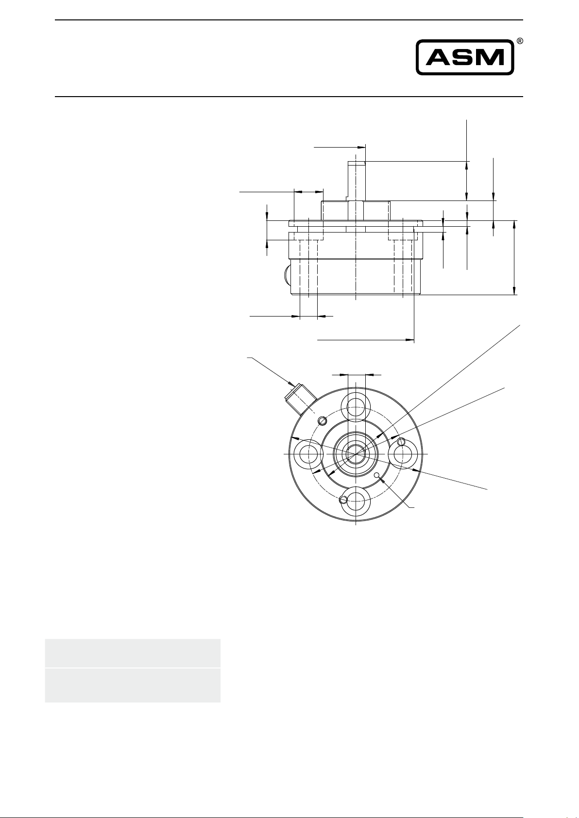
POSIROT
®
Instruction Manual
Outline drawing
PRAS5-V
Connector M12
radial
M12-Stecker
]
7
8
10 [.394]
15 [.591]Ø
]
4
9
3
.
[
0
1
.7
[
0
2
]
4
9
.3
[
0
1
]
]
8
8
1
1
1
.
.1
[
[
3
3
]
6
9
4
.
1
[
8
3
9 [.354]Ø
]
)
1
0
6
0
1
.
-
Ø60 [2.362]
9 [.354]
1
4
.
1
[
3
)
0
,
4
0
-
0
,
0
-
(
f6
6
3
8
4
.89
1
[
5
0
,
0
0
0
.
-
(
6
f
7
]
2
0
0
.
0
Allowable shaft load
(10 mm shaft)
100 N radial, 100 N axial
6
Markierung
Dimensions in mm [inch]
Dimensions informative only.
For guaranteed dimensions consult factory.
8
,
2 [
2
.
6
8
5
]
20 MAN-PRAS-E-15 ASM GmbH
www.asm-sensor.com
Page 21
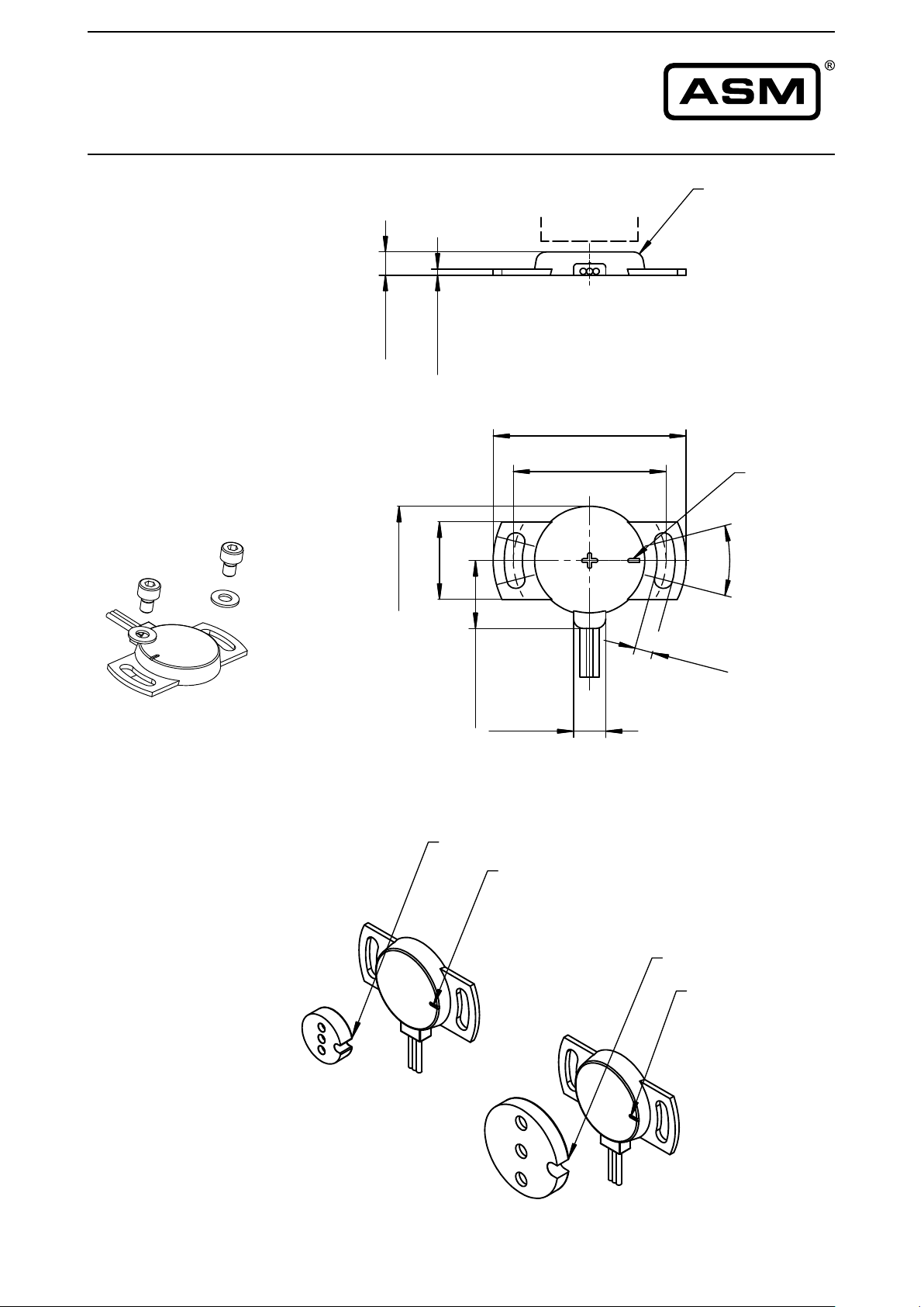
Positions-
magnet
38 [1.496]Ø
48 [1.890]Ø
2
8
[
1
.1
0
2
]
2
0
[
.
7
8
7
]
3
0
°
4
,
5
[
.
1
7
7
]
1
,6
[
.0
6
3
]
6
[
.2
3
6
]
Messfläche
Markierung
8 [.315]
1
7
,
5
[
.
6
8
9
]
POSIROT
®
Instruction Manual
Outline drawing
PRAS20
Dimensions in mm [inch]
Dimensions informative only.
For guaranteed dimensions
consult factory.
M4
M4
Position
magnet
Measuring area
Marking
Reference
position
(see page 7)
Marking
Marking
Marking
Marking
ASM GmbH MAN-PRAS-E-15 21
www.asm-sensor.com
Page 22
POSIROT
®
Instruction Manual
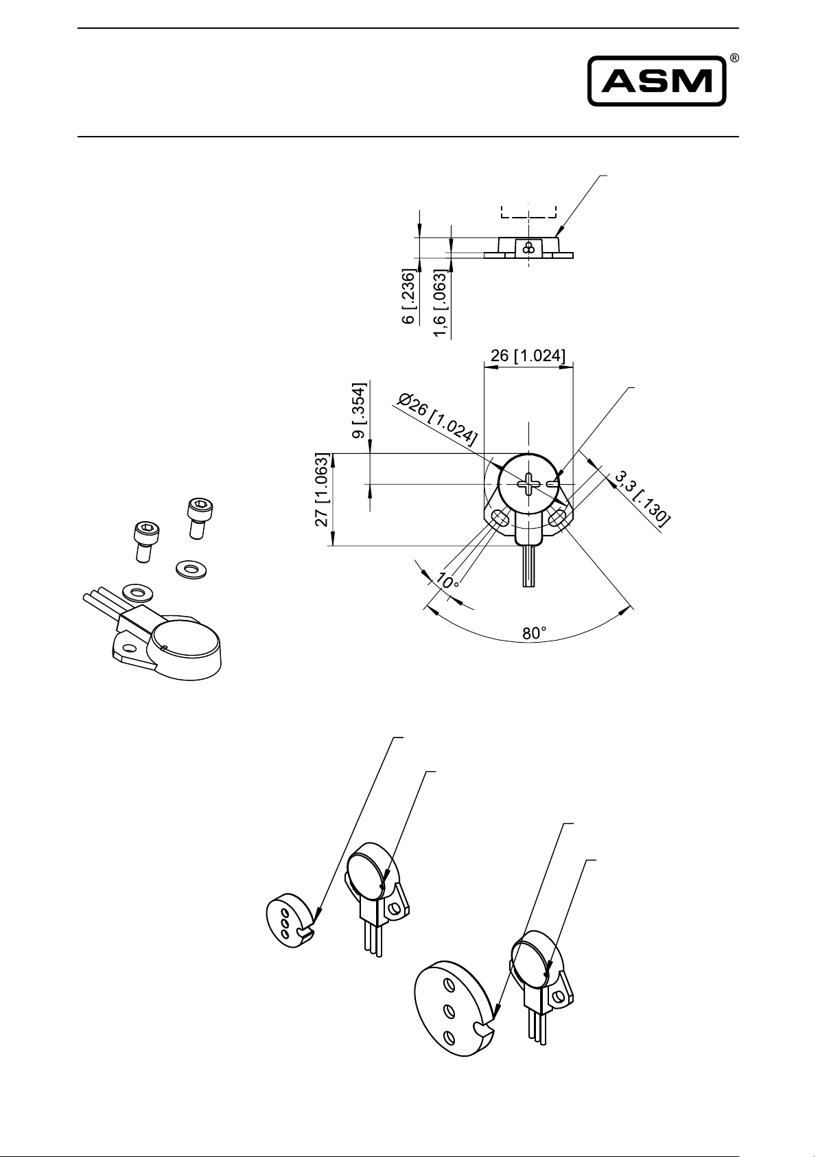
Outline drawing
PRAS21
Dimensions in mm [inch]
Dimensions informative only.
For guaranteed dimensions
consult factory.
M3
M3
Position
magnet
Measuring area
Marking
Reference
Marking
position
(see page 7)
22 MAN-PRAS-E-15 ASM GmbH
www.asm-sensor.com
Marking
Marking
Marking
Page 23
POSIROT
®
Instruction Manual
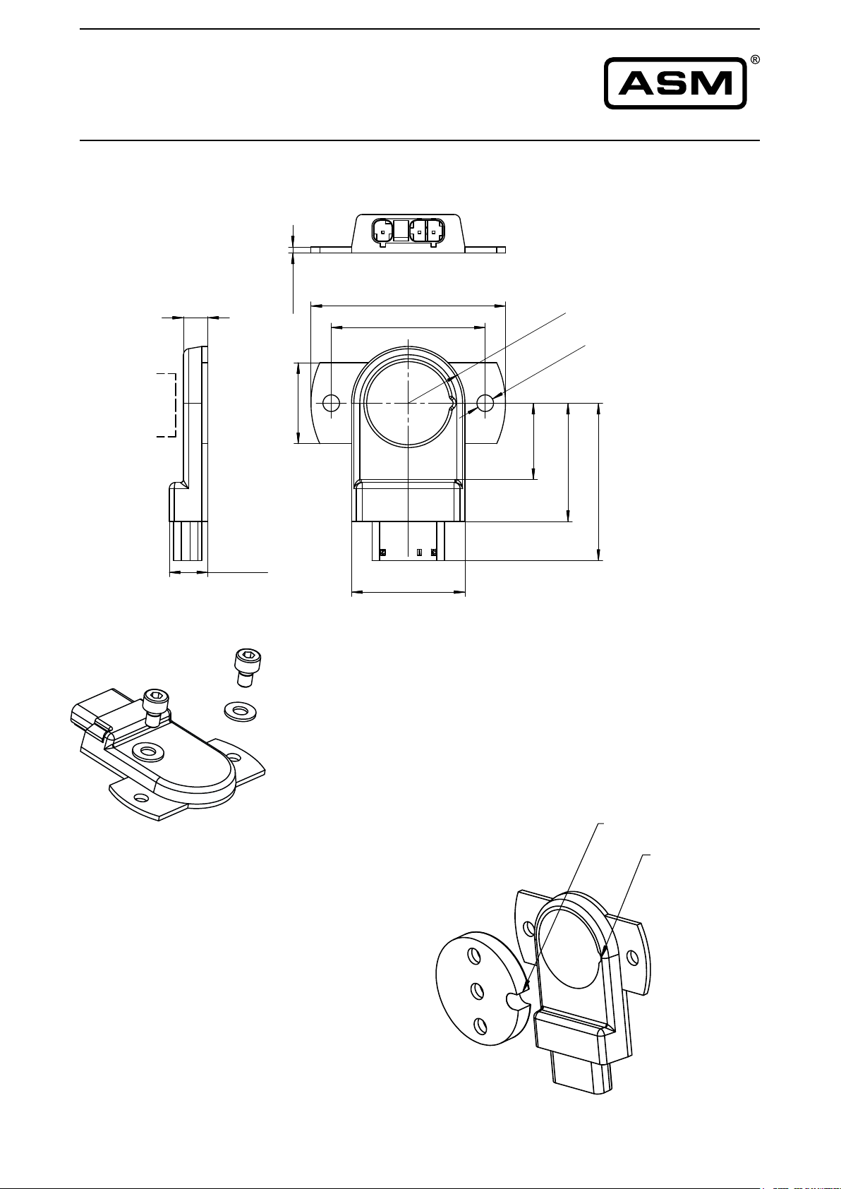
Outline drawing
PRAS26
6 [.236]
Positionsmagnet /
position magnet
9,5 [.374]
Dimensions in mm [inch]
Dimensions informative only.
For guaranteed dimensions
consult factory.
]
9
5
0
.
[
5
,
1
]
7
8
.7
[
0
2
38 0,05
48 [1.890]Ø
[ ]
1.496
28 [1.102]
.002
]
51
5
[.
4
1
R
]
0
4
.7
[
,8
8
1
]
1
6
1
.
[
1
,
4
]
0
5
1
]
.
8
1
[
2
2
.5
,
1
9
[
2
,8
8
3
M4
M4
Reference
position
(see page 7)
Markierung
Marking
Marking
Markierung
ASM GmbH MAN-PRAS-E-15 23
www.asm-sensor.com
Page 24
POSIROT
®
Instruction Manual
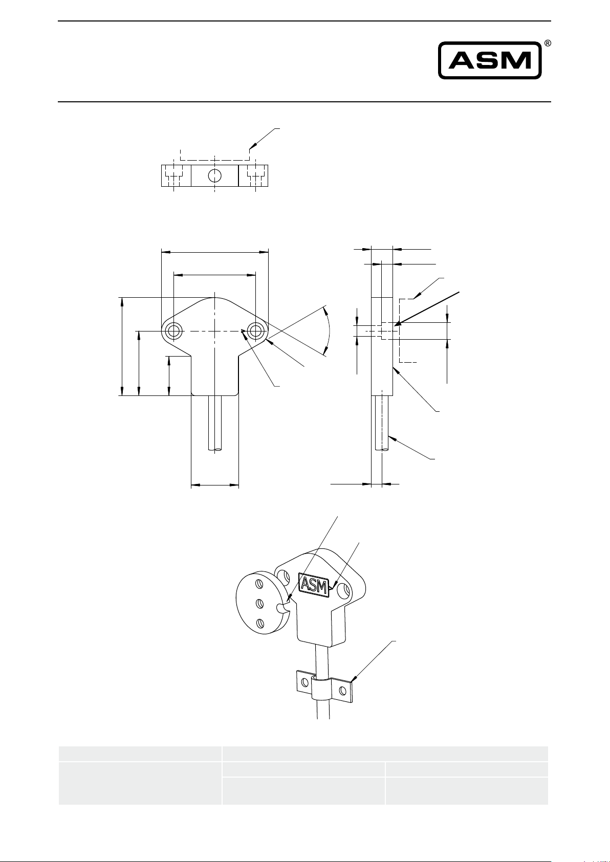
Outline drawing
PRAS27
]
1
9
.7
1
]
[
1
8
,5
5
4
]
.1
7
1
1
[
.7
0
[
3
,2
8
1
49,5 0,1
38 [1.496]
[ ]
1.949
.004
Positionsmagnet /
Position magnet
position magnet
°
0
R
6
,
3
[.
2
4
Markierung /
Marking
marking
6
8
]
Dimensions in mm [inch]
Dimensions informative only.
For guaranteed dimensions
consult factory.
10 [.394]
5,2 [.205]
Positionsmagnet /
Position magnet
position magnet
for screws according
DIN 912-M4
(ISO 4762)
or
]
7
9
1
.
[
5
Ø
DIN 6912-M4
or
]
7
0
DIN 7984-M4
3
.
[
,8
7
Ø
Meßfläche /
Measuring area
measurement area
Reference
position
(see page 7)
For all sensors with cable:
Cable diameter Ø 5,2 mm
Min. bending radius
22 [.866]
Kabel /
Cable
5 [.197]
Marking
Markierung
Markierung
Marking
Zugentlastung
Strain relief
cable
in motion not in motion
10 x cable diameter,
10 million cycles
5 x cable diameter
24 MAN-PRAS-E-15 ASM GmbH
www.asm-sensor.com
Page 25
POSIROT
®
Instruction Manual
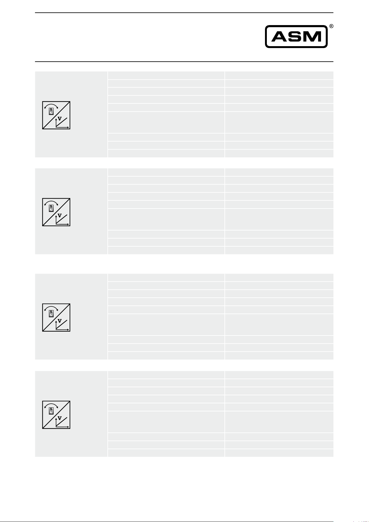
Analog output
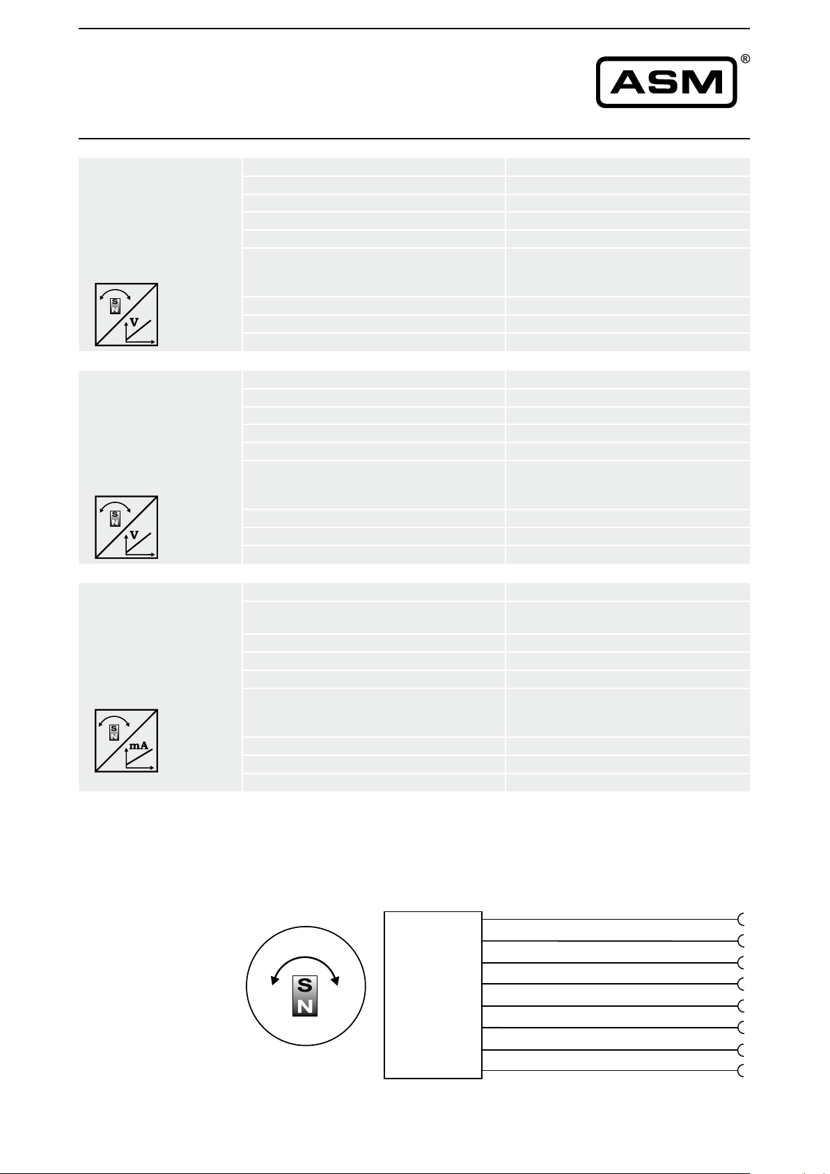
U2
Voltage Output
0.5 ... 10 V
U2B
Voltage Output
0.5 ... 10 V
Excitation voltage
Excitation current 10 mA typ., 15 mA max.
Output voltage 0.5 ... 10 V DC
Output current 2 mA max.
Measuring rate 1 kHz standard
Stability (temperature) ±50 x 10
Operating temperature -40 ... +85 °C (+105 °C as option)
Protection Reverse polarity, short circuit
EMC EN 61326-1:2013
Excitation voltage
Excitation current 12 mA typ., 16 mA max.
Output voltage 0.5 ... 10 V DC
Output current 2 mA max.
Measuring rate 1 kHz standard
Stability (temperature) ±50 x 10
Operating temperature -40 ... +85 °C (+105 °C as option)
Protection Reverse polarity, short circuit
EMC EN 61326-1:2013
18 ... 36 V DC
-6
/ °C f.s. (typ.) for
90°...360°
±100 x 10-6 / °C f.s. (typ.) for <90°
11.5 ... 27 V DC
-6
/ °C f.s. (typ.) for
90°...360°
±100 x 10-6 / °C f.s. (typ.) for <90°
U6
Voltage Output
10 ... 90% ratiometr.
U6/8,25
Voltage Output
10 ... 90% ratiometr.
Excitation voltage 5V DC ±10 %
Excitation current 8 mA typ., 12 mA max.
Output voltage 10 ... 90 % of the excitation voltage
Output current 2 mA max.
Measuring rate 1 kHz standard
Stability (temperature) ±50 x 10
90°...360°
±100 x 10-6 / °C f.s. (typ.) for <90°
Operating temperature
Protection Reverse polarity, short circuit
EMC EN 61326-1:2013
Excitation voltage 8.25 V DC ±10 %
Excitation current 8 mA typ., 12 mA max.
Output voltage 10 ... 90 % of the excitation voltage
Output current 2 mA max.
Measuring rate 1 kHz standard
Stability (temperature) ±50 x 10
Operating temperature
Protection Reverse polarity, short circuit
EMC EN 61326-1:2013
-40 ... +85 °C (+125 °C as option)
90°...360°
±100 x 10-6 / °C f.s. (typ.) for <90°
-40 ... +85 °C (+125 °C as option)
-6
/ °C f.s. (typ.) for
-6
/ °C f.s. (typ.) for
ASM GmbH MAN-PRAS-E-15 25
www.asm-sensor.com
Page 26

POSIROT
®
Instruction Manual
Analog output
U8
Voltage Output
0,5 ... 4,5 V
I1
Current Output
4 ... 20 mA, 3 wire
Excitation voltage 11 ... 36 V DC
Excitation current 10 mA, typ. 20 mA max.
Output voltage 0,5 ... 4,5 V DC
Output current 2 mA max.
Measuring rate 1 kHz standard
Stability (temperature) ±50 x 10
-6
/ °C f.s. (typ.) for
90°...360°
±100 x 10-6 / °C f.s. (typ.) for <90°
Operating temperature -40 ... +85 °C
Protection Reverse polarity, short circuit
EMC EN 61326-1:2013
Excitation voltage 18 ... 36 V DC
Excitation current 30 mA typical, 35 mA max.
Load resistor 500 Ω max.
Output current 4 ... 20 mA
Measuring rate 1 kHz standard
Stability (temperature) ±50 x 10
-6
/ °C f.s. (typ.) for
90°...360°
±100 x 10-6 / °C f.s. (typ.) for <90°
Operating temperature -40 ... +85 °C
Protection Reverse polarity, short circuit
EMC EN 61326-1:2013
I1B
Current Output
4 ... 20 mA, 3 wire
Other outputs on request.
Output signals
Excitation voltage 10 ... 27 V DC
Excitation current 32 mA typical, 36 mA max.
Load resistor 200 Ω max.
Output current 4 ... 20 mA
Measuring rate 1 kHz standard
Stability (temperature) ±50 x 10
-6
/ °C f.s. (typ.) for
90°...360°
±100 x 10-6 / °C f.s. (typ.) for <90°
Operating temperature -40 ... +85 °C
Protection Reverse polarity, short circuit
EMC EN 61326-1:2013
Excitation +
U2 / U2B
U6 / U6/8,25
U8
I1 / I1B
Signal +
GND
26 MAN-PRAS-E-15 ASM GmbH
www.asm-sensor.com
Page 27
POSIROT
®
Instruction Manual
Analog output, redundant
U2R
Voltage Output
0.5 ... 10 V
U8R
Voltage Output
0,5 ... 4,5 V
Excitation voltage
18 ... 36 V DC
Excitation current 10 mA typ., 15 mA max. per channel
Output voltage 0.5 ... 10 V DC
Output current 2 mA max.
Measuring rate 1 kHz standard
-6
Stability (temperature) ±50 x 10
/ °C f.s. (typ.) for
90°...360°
±100 x 10-6 / °C f.s. (typ.) for <90°
Operating temperature -40 ... +85 °C (+105 °C as option)
Protection Reverse polarity, short circuit
EMC EN 61326-1:2013
Excitation voltage 11 ... 36 V DC
Excitation current 10 mA, typ. 20 mA max. per channel
Output voltage 0,5 ... 4.5 V DC
Output current 2 mA max.
Measuring rate 1 kHz standard
Stability (temperature) ±50 x 10
-6
/ °C f.s. (typ.) for
90°...360°
±100 x 10-6 / °C f.s. (typ.) for <90°
Operating temperature -40 ... +85 °C
Protection Reverse polarity, short circuit
EMC EN 61326-1:2013
I1R
Current Output
4 ... 20 mA, 3 wire
Excitation current 30 mA typical, 35 mA max. per
Load resistor 500 Ω max.
Output current 4 ... 20 mA
Measuring rate 1 kHz standard
Stability (temperature) ±50 x 10
Operating temperature -40 ... +85 °C (-40 ... +185 °F)
Protection Reverse polarity, short circuit
EMC EN 61326-1:2013
Other outputs available on request.
Excitation voltage 18 ... 36 V DC
U2R
U8R
I1R
channel
-6
/ °C f.s. (typ.) for
90°...360°
±100 x 10-6 / °C f.s. (typ.) for <90°
Excitation +
Signal +
GND
Do not connect!
Excitation +
Signal +
GND
Do not connect!
ASM GmbH MAN-PRAS-E-15 27
www.asm-sensor.com
Page 28
POSIROT
®
Instruction Manual
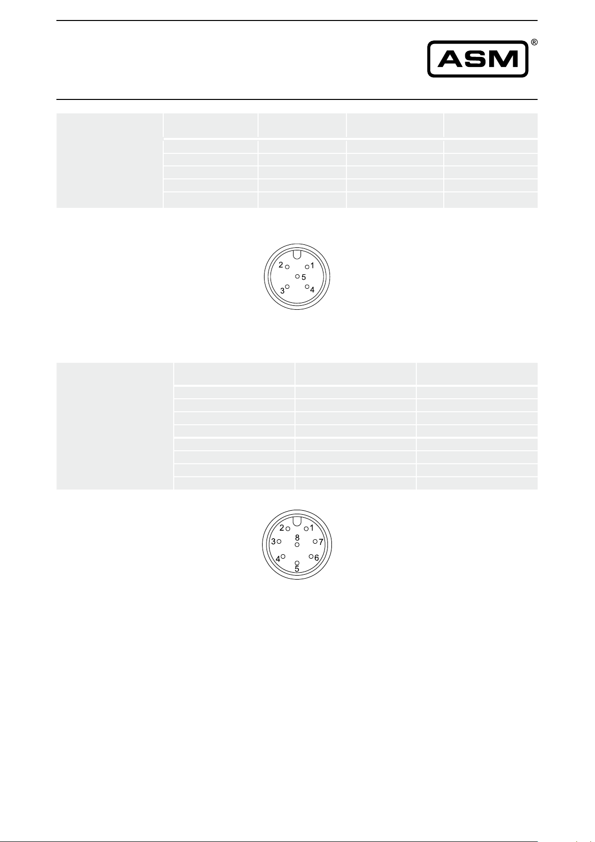
Signal wiring
Signal wiring
1 channel
M12A4/5, M12R4/5
4/5 pin
(Plug and cable
connection)
Connection
Signal wiring
2 channel
redundant version
M12, 8 pin
(Plug and
cable connection)
Signal Plug connection
Excitation + 1 brown white
Signal 2 white green
GND 3 blue brown
Do not connect! 4 black –
Do not connect! 5
3-wire current 4...20 mA interface: GND has to be connected!
View to sensor
connector
Signal Plug connection Cable connection
CH1-Excitation + 1 white
CH1-Signal 2 brown
CH1-GND 3 green
CH1-Do not connect! 4 yellow
CH2-Excitation + 5 grey
CH2-Signal 6 pink
CH2-GND 7 blue
CH2-Do not connect! 8 red
Cable connection
[BN-WH-BU-BK]
Cable connection
[WH-GN-BN]
Connection
View to sensor
connector
28 MAN-PRAS-E-15 ASM GmbH
www.asm-sensor.com
Page 29
POSIROT
®
Instruction Manual
Signal wiring
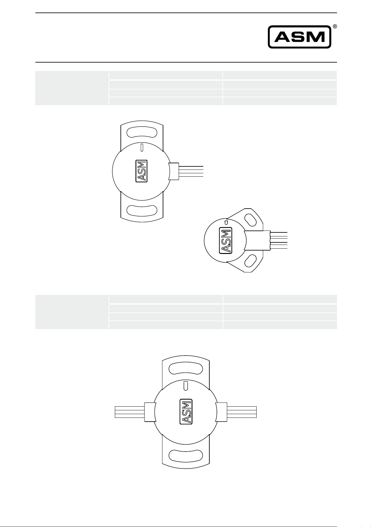
Signal Wiring
PRAS20 / PRAS21
Connection
Signal Wires
Excitation + brown
Signal white
GND blue
Signal
GND
Excitation +
PRAS20
Signal
Excitation +
GND
Signal Wiring
PRAS20R
(redundant version)
Connection
Excitation +
PRAS21
Signal Wires
Excitation + brown
Signal white
GND blue
Signal
GND
GND
Excitation +
Signal
PRAS20R
ASM GmbH MAN-PRAS-E-15 29
www.asm-sensor.com
Page 30
POSIROT
®
Instruction Manual
Signal wiring
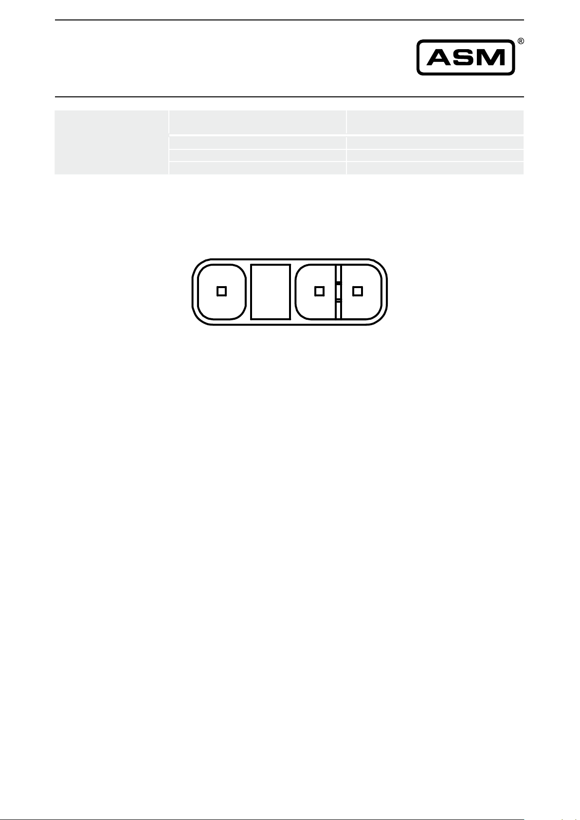
Signal wiring
PRAS26
TE3, 3 pin
Connection
Signal Plug connection
GND 1
Excitation + 2
Signal 3
2 31
View to sensor
connector
Connector TE3
(Connector cable see page 32)
30 MAN-PRAS-E-15 ASM GmbH
www.asm-sensor.com
Page 31
POSIROT
®
Instruction Manual
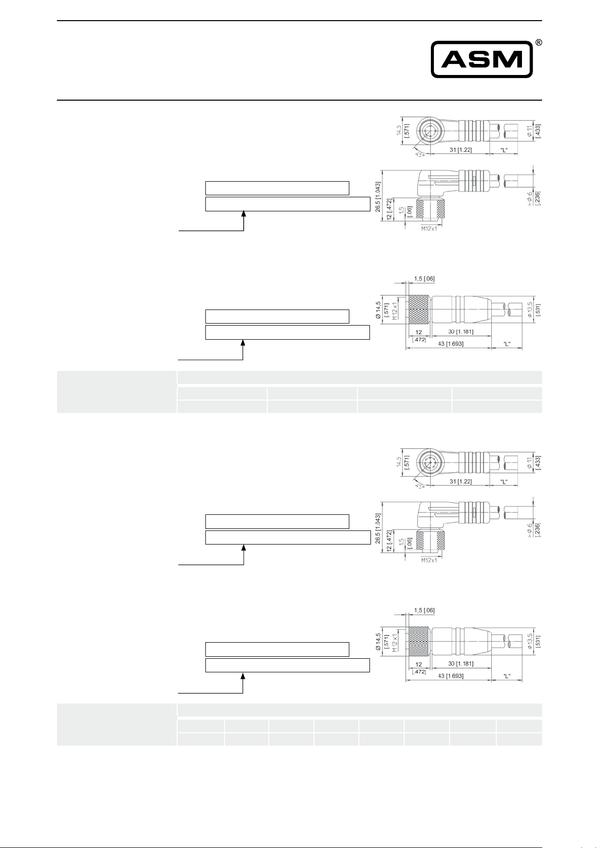
Accessory cables
Connector cable
M12, 4-pin
shielded*
Suitable for 5-pin
sensor connectors
M12A5 and M12R5
Connector cable
M12, 4-pin
shielded*
Suitable for 5-pin
sensor connectors
M12A5 and M12R5
Signal wiring
M12, 4 pin
The 4-core screened cable is supplied with a
mating 4-pin 90° M12 connector at one end
and 4 wires at the other end. Available lengths
are 2, 5 and 10 m. Cross section 0.34 mm
Order code:
2
KAB - XM - M12/4F/W - LITZE
IP69K:
Length in m
The 4-core screened cable is supplied with a
mating 4-pin M12 connector at one end and 4
wires at the other end. Available lengths are 2,
5 and 10 m. Cross section 0.34 mm
Order code:
KAB - XM - M12/4F/W/69K - LITZE
2
KAB - XM - M12/4F/G - LITZE
IP69K:
Length in m
KAB - XM - M12/4F/G/69K - LITZE
Plug connection / Cable connection
1 2 3 4
brown white blue black
Connector cable
M12, 8-pin
shielded*
Connector cable
M12, 8-pin
shielded*
Signal wiring
M12, 8-pin
* = shielded connector
The 8-core screened cable is supplied with a
mating 8-pin 90° M12 connector at one end
and 8 wires at the other end. Available lengths
are 2, 5 and 10 m. Cross section 0.25 mm
Order code:
2
KAB - XM - M12/8F/W - LITZE
IP69K:
Length in m
The 8-core screened cable is supplied with a
mating 8-pin M12 connector at one end and 8
wires at the other end. Available lengths are 2,
5 and 10 m. Cross section 0.25 mm
Order code:
KAB - XM - M12/8F/W/69K - LITZE
2
KAB - XM - M12/8F/G - LITZE
IP69K:
Length in m
KAB - XM - M12/8F/G/69K - LITZE
Plug connection / Cable connection
1 2 3 4 5 6 7 8
white brown green yellow grey pink blue red
* = shielded connector
ASM GmbH MAN-PRAS-E-15 31
www.asm-sensor.com
Page 32
POSIROT
®
Instruction Manual
Accessory cables
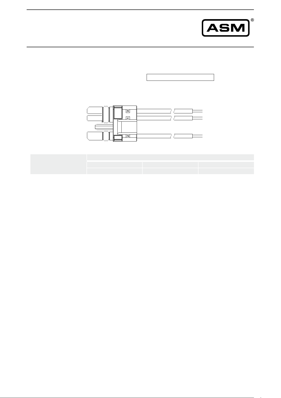
Connector cable
PRAS26
Connector, 3-pin
Signal wiring
Signal wiring
3-pin connector
3-pin connector
This cable is supplied with a male 3-pin connector at one end and 3
wires at the other end. Cross section 0.32 mm
Order code:
CONN-TE-3F-G-LITZE-0,5M
2
.Wire length 0.5 m.
3
1
2
Connector pin / cable color
Plug connection / Wires
1 2 3
1 2 3
blue brown white
blue brown white
32 MAN-PRAS-E-15 ASM GmbH
www.asm-sensor.com
Page 33
POSIROT
®
Instruction Manual
Accessories
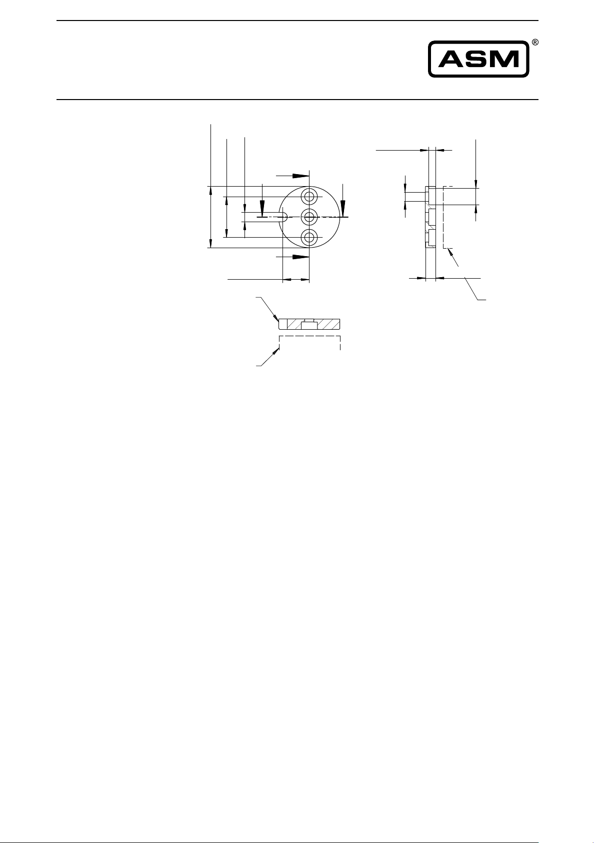
Position magnet
PRMAG20
]
1
8
.1
1
[
0
3
Ø
Markierung
/ marking
]
]
7
7
7
8
1
7
.
.
[
[
5
0
,
2
4
13 [.512]
Sensor /
sensor
K
J J
K
3,5 [.138]
]
7
7
1
.
[
5
,
4
5 [.197]
]
5
1
.3
[
8
Sensor /
sensor
Dimensions in mm [inch]
Dimensions informative only.
For guaranteed dimensions consult factory.
Weight 11 g approx.
Moment of inertia 1.2 kgmm
2
ASM GmbH MAN-PRAS-E-15 33
www.asm-sensor.com
Page 34
POSIROT
®
Instruction Manual
Accessories
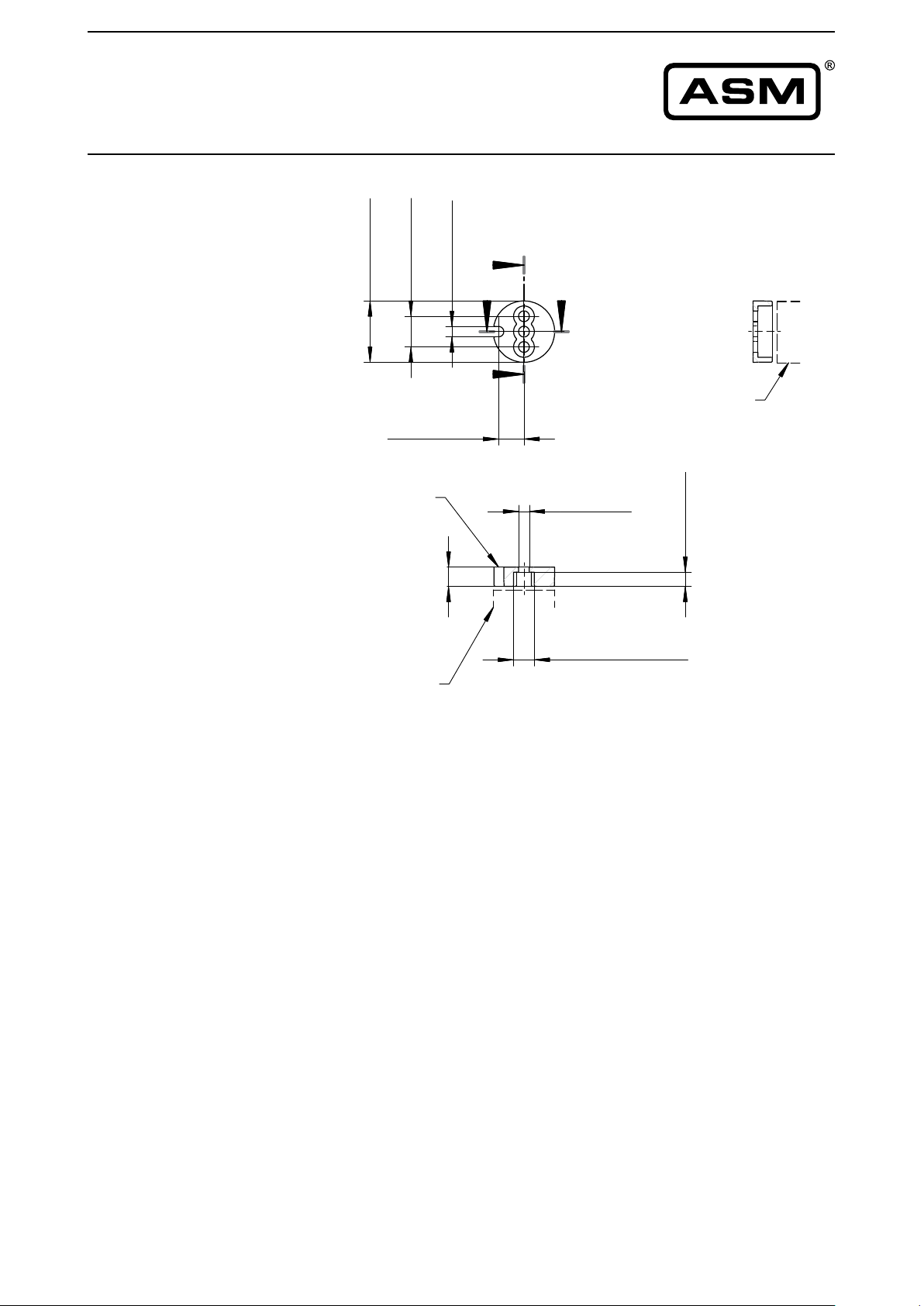
Position magnet
PRMAG21
]
]
5
0
1
3
3
6
.
.
[
[
8
6
1
6,6 [.260]
Markierung /
marking
]
6
0
1
.
[
7
J
,
2
K K
J
]
7
9
1
.
[
5
2,7 [.106]
Sensor /
sensor
]
6
4
.1
[
,7
3
Sensor /
sensor
Dimensions in mm [inch]
Dimensions informative only.
For guaranteed dimensions consult factory.
5,4 [.213]Ø
Weight 3 g approx.
Moment of inertia 0.1 kgmm
2
34 MAN-PRAS-E-15 ASM GmbH
www.asm-sensor.com
Page 35
POSIROT
®
Instruction Manual
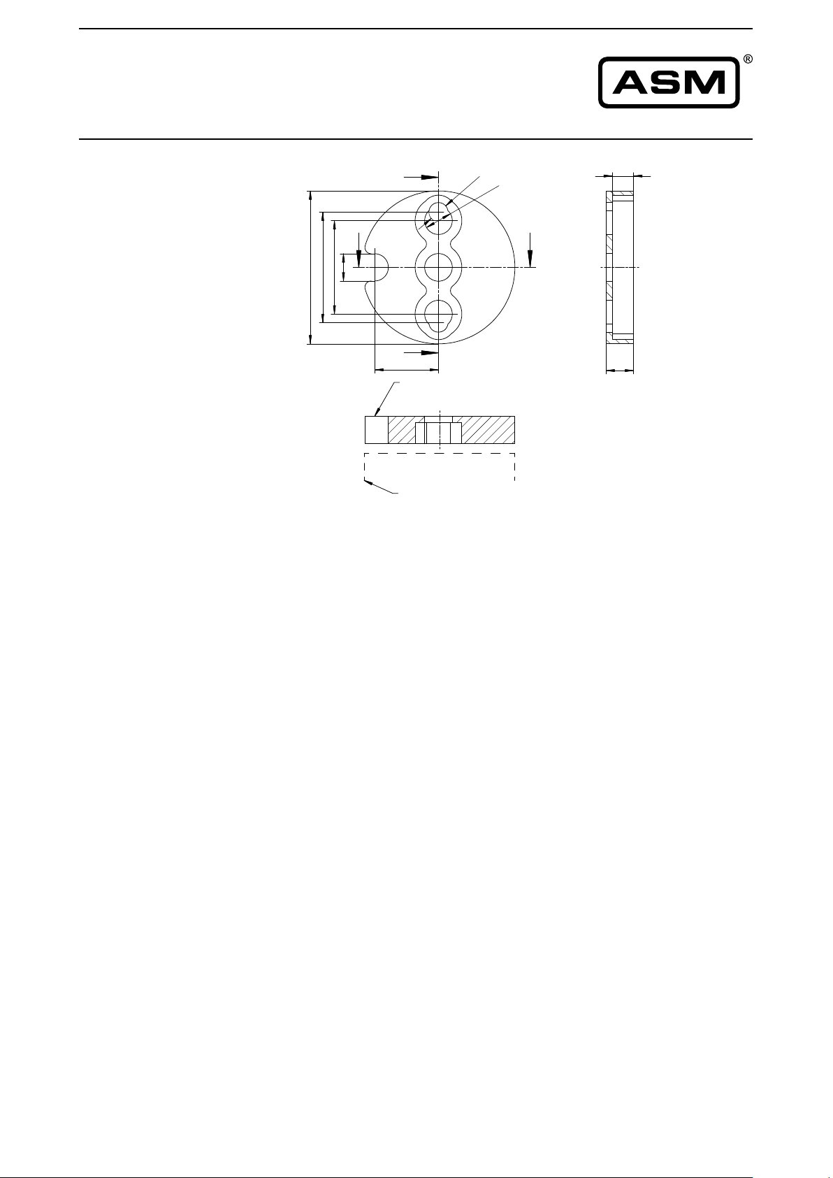
Accessories
Position magnet
PRMAG22
5
E
F
2
6
6
,4
2
3
2
6
E
15
Markierung /
marking
,
4
5
,
6
F
5
6,5
Weight 17 g approx.
2
Sensor /
sensor
Moment of inertia 3 kgmm
Dimensions in mm [inch]
Dimensions informative only.
For guaranteed dimensions consult factory.
ASM GmbH MAN-PRAS-E-15 35
www.asm-sensor.com
Page 36
POSIROT
®
Instruction Manual
Accessories
Position magnet
PRMAG5-Z
Nut / notch
]
7
9
.1
[
5
Markierung /
marking
]
1
9
5
.
[
5
1
G
]
4
5
.3
[
9
10 [.394]
HH
]
3
2
3
.
[
,2
8
G
Ø
Ø
0,05
48
66
-
[ ]
1.890
0+
2.598
0,1
[ ]
0.002
0+
-
0.004
14 [.551]
Sensor /
sensor
Sensor /
sensor
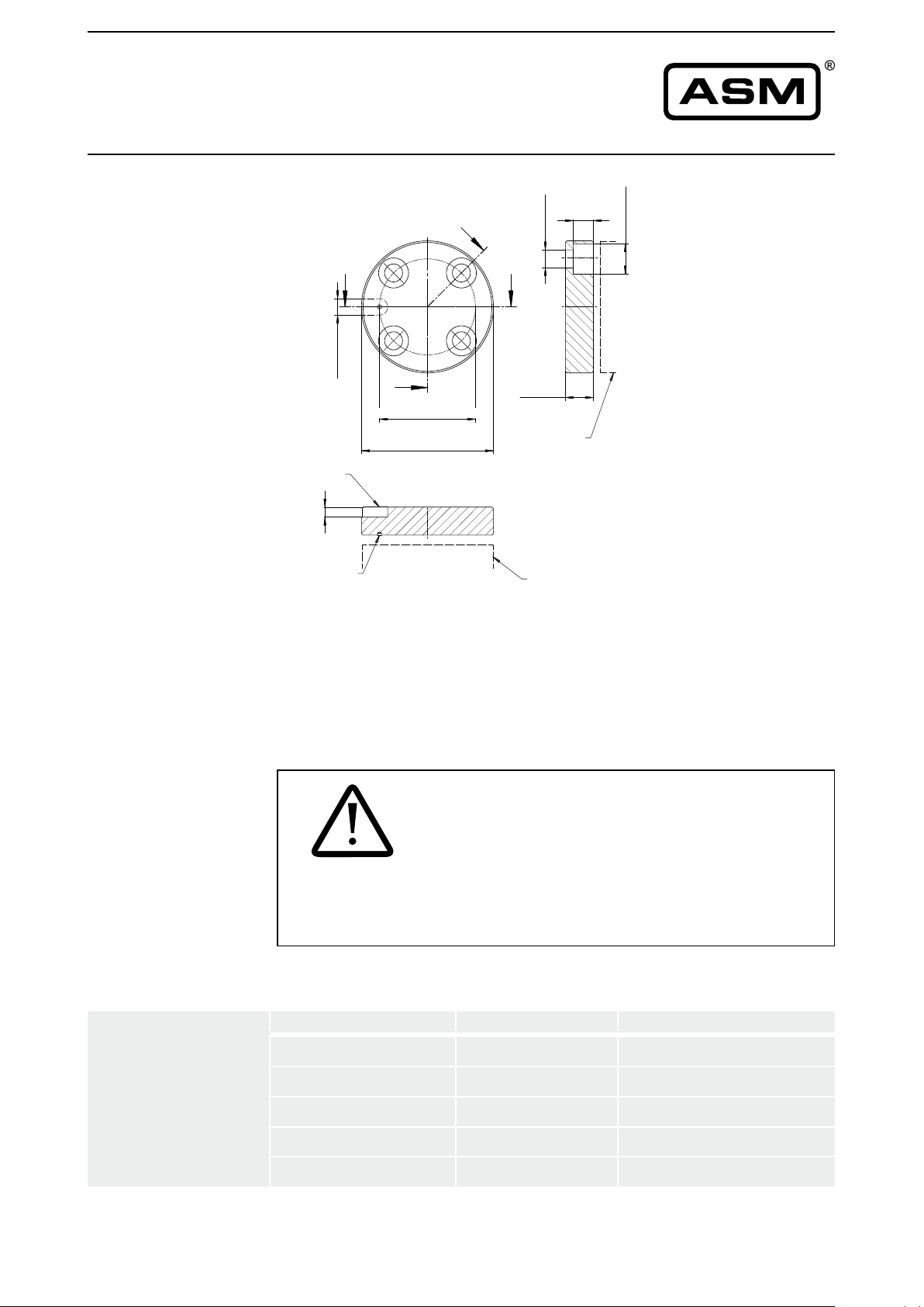
Weight 100 g approx.
Moment of inertia 55 kgmm
2
Fixing of the
position
magnets
Mounting of the
magnets
Dimensions in mm [inch]
Dimensions informative only.
For guaranteed dimensions consult factory.
Adjacentmagneticeldsorferromagneticmaterials
caninuencethemeasurementresultsofthePRAS
sensors of the POSIROT® product family. Therefore
the angle sensors should be mounted solely with
NOTICE
Magnet Mounting method Material
PRMAG20 Screw(s) M4 A4
PRMAG21 Screw(s) M2.5 A4
PRMAG22 Screw(s) M4 or M6 A4
nonmagnetic / non magnetisable screws.
PRMAG5-Z Screws M8
Anti-rotation element –
A2 or non-magnetic
A2
36 MAN-PRAS-E-15 ASM GmbH
www.asm-sensor.com
Page 37
unmagnetisches
Material
(z.B. Al, POM usw.)
PRMAG
bündig nicht bündig
POSIROT
®
Instruction Manual
Accessories
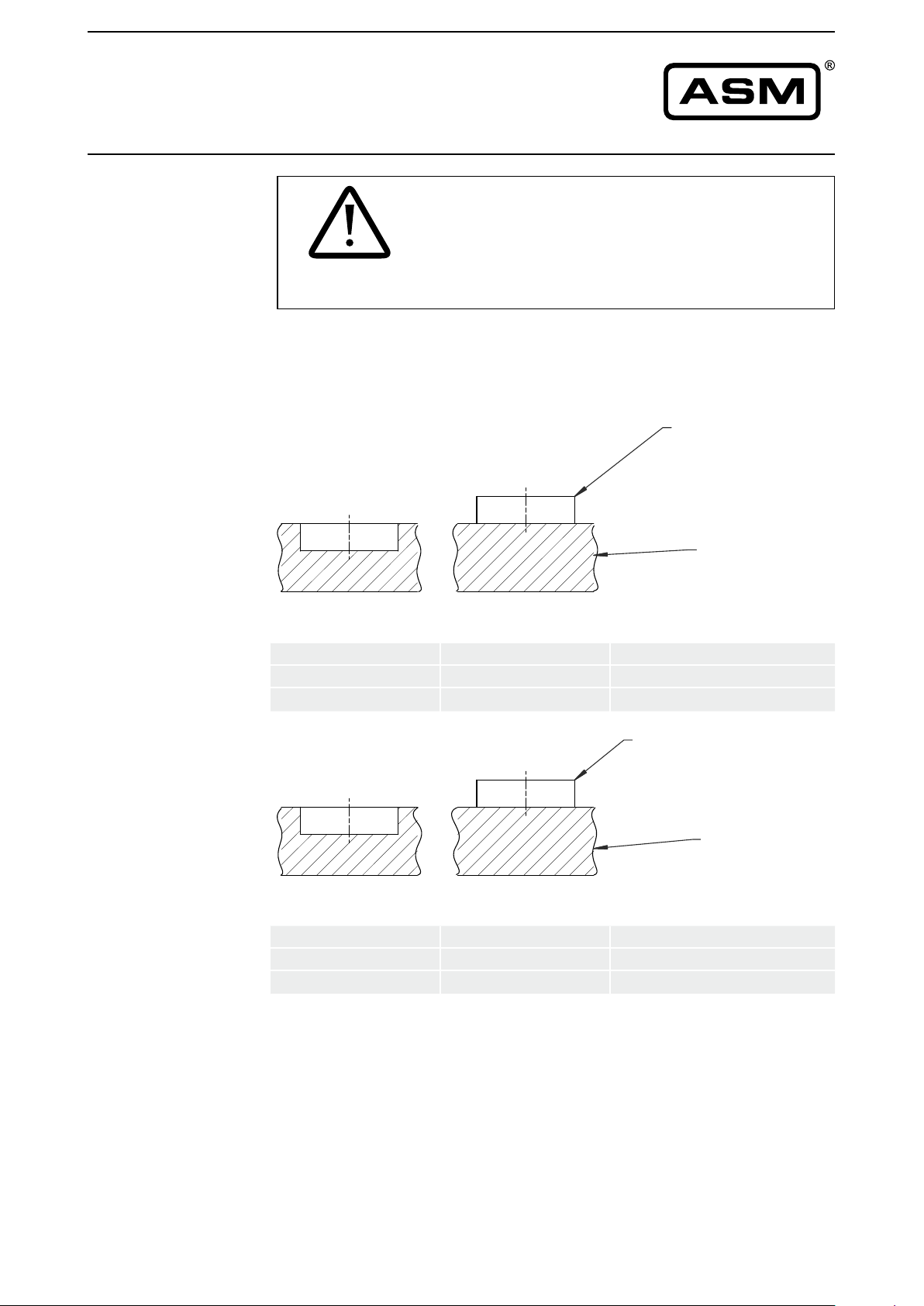
Assembly of
the position
magnets
Usually it is not admissible to countersink a position
magnet into ferromagnetic material, because
this would have a negative inuence on the
performance of the position magnet, and could lead
NOTICE
flush-mounted surface-mounted
bündig nicht bündig
to measurement errors of the PRAS angle sensors.
PRMAG
unmagnetisches
Non magnetic
Material
material
(z.B. Al, POM usw.)
(e.g. Al, POM etc.)
flush-mounted
bündig nicht bündig
–
–
surface-mounted
PRMAG5-Z
PRMAG20
PRMAG21/22
PRMAG
magnetisches
Magnetic material
Material
(e.g. St, Ck etc.)
(z.B. St, Ck usw.)
PRMAG5-Z
PRMAG20
PRMAG21/22
ASM GmbH MAN-PRAS-E-15 37
www.asm-sensor.com
Page 38
POSIROT
®
Instruction Manual
Accessories
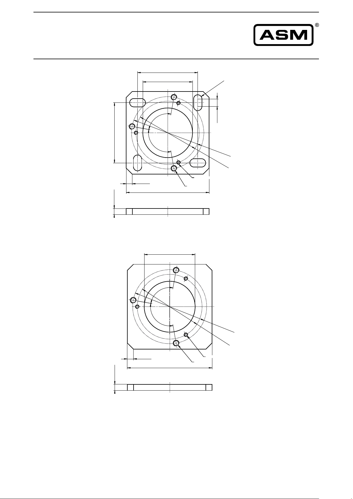
Mounting plate
PRPT-BPL1
40 [1.575]
33 [1.299]Ø
]
7
.21
[
5
,
5
In combination with the
mounting clamps
PRPT-BFS1 (3 x M2.5)
]
°
0
9
]
5
7
5
.
1
[
0
4
]
7
5
.1
[
4
4 [.157]
1
1
0
°
3x M2,5
55 [2.165]
3x M4
7
9
.1
[
5
48
[
1
.
8
9
0
4
2
[
1
.
6
5
4
]
or
in combination with the
mounting bracket
PRPT-BFS2 (3 x M4).
]
Mounting plate
PRPT-BPL2
(welding assembly)
33 [1.299]Ø
°
0
9
1
1
0
°
4 [.157]
]
7
5
.1
[
4
55 [2.165]
3x M2,5
3x M4
Dimensions in mm [inch]
Dimensions informative only.
For guaranteed dimensions consult factory.
In combination with the
mounting clamps
4
8 [
1
.
8
4
2
[
1
.
6
5
4
PRPT-BFS1 (3 x M2.5)
or
9
0
]
in combination with the
mounting bracket
]
PRPT-BFS2 (3 x M4).
38 MAN-PRAS-E-15 ASM GmbH
www.asm-sensor.com
Page 39
POSIROT
®
Instruction Manual
Accessories
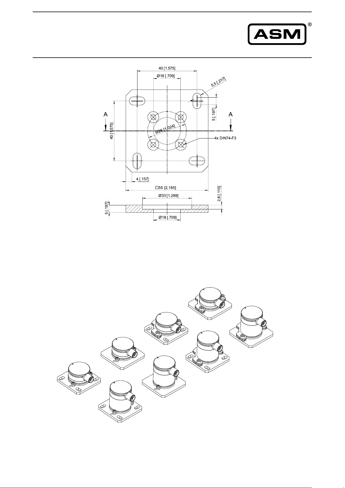
Mounting plate
PRPT-BPL3
Dimensions in mm [inch]
Dimensions informative only.
For guaranteed dimensions consult factory.
Mounting possibilities
PRAS2/PRAS3
PRPT-BPL2
+
PRPT-BFS2
PRPT-BPL1
+
PRPT-BFS2
PRPT-BPL2
+
PRPT-BFS1
PRPT-BPL1
+
PRPT-BFS1
ASM GmbH MAN-PRAS-E-15 39
www.asm-sensor.com
Page 40
ØA
ØB
3
7
-
0
0
,
2
+
1
.
4
5
7
-
0
.0
0
8
+
[
]
1
1
[
.
4
3
3
]
1
1
[
.4
3
3
]
POSIROT
®
Instruction Manual
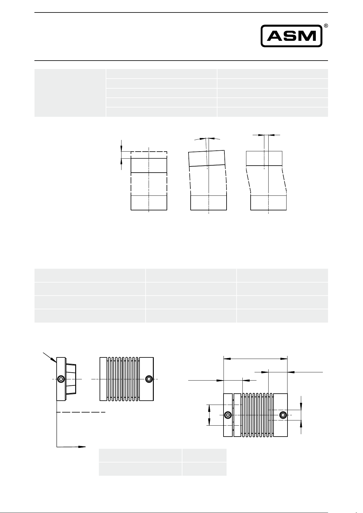
Couplings
Model MK4
Maximum
misalignment
Rated torque
Total length (inserted)
Axial misalignment (a) < 0.7 mm
Angular misalignment (b) < 2°
Lateral misalignment (c) < 0.25 mm
°
2
]
6
7
2
0
.
[
7
,
0
2 Nm
37 mm
0,25 [.0098]
a b c
Dimensions in mm [inch]
Order code A B
MK4-37-6-6 Ø6 [.236 +.0005] Ø 6 [.236 +.0005]
MK4-37-6-10 Ø6 [.236 +.0005] Ø10 [.394 +.0006]
MK4-37-6-12 Ø6 [.236 +.0005] Ø12 [.472 +.0007]
axially pluggable
.0
8
2
,
0
+
7
3
-
0
]
3
3
4
.
[
1
1
ØB
4
.
1
[
0
+
7
5
]
-
0
]
3
3
4
.
[
1
1
ØA
pluggable side
Screws (ISO4029) 2 x M4
Torque 2,5 Nm
40 MAN-PRAS-E-15 ASM GmbH
www.asm-sensor.com
Dimensions in mm [inch]
Page 41

POSIROT
®
Instruction Manual
Service, calibration, disposal
Service
Calibration
Sensors and accessories have to be repaired and adjusted at ASM in
Moos inning.
In order to avoid risk of injury and improper handling the customer is not
allowed to repair the sensor. No warranty or liability will be granted for opened sensors.
Damaged sensors must be shut down immediately and sent to the factory
for repair.
The recommended calibration interval is 1 year.
Test protocol is available on request.
Disposal
Disposal according to applicable government regulations.
ASM GmbH MAN-PRAS-E-15 41
www.asm-sensor.com
Page 42
POSIROT
®
Instruction Manual
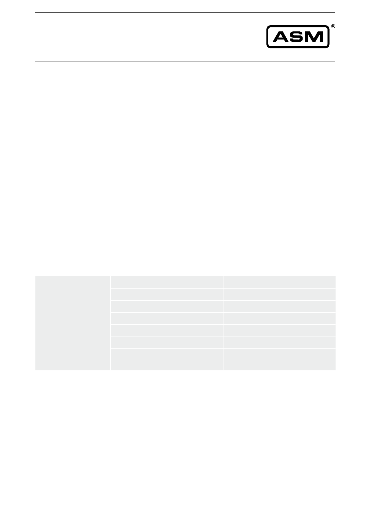
Reliability Characteristics
Models
PRAS1, PRAS2, PRAS3, PRAS5,
PRAS20, PRAS20R, PRAS21, PRAS26, PRAS27
U2 Voltage output 0,5 ... 10 V
U2R Voltage output 0,5 ... 10 V
U2B Voltage output 0,5 ... 10 V
U6 Voltage output 0,5 ... 4,5 V
U6/8,25 Voltage output 0,825 ... 7,425 V
U8 Voltage output 0,5 ... 4,5 V
U8R Voltage output 0,5 ... 4,5 V
I1 Current output 4 ... 20 mA
I1R Current output 4 ... 20 mA
I1B Current output 4 ... 20 mA
Characteristics
Standards
Device type B
Probability of failure PFH (λ
Life period MTTF
Working life
Mechanical life period L
Max. revolutions
Allowable shaft load
(10 mm solid shaft, 6 mm hollow shaft)
d
) 877 Fit
DU
10
130 years
10 years
100 x 106 revolutions
10.000 1/min
100 N radial, 100 N axial
IEC 61508-1, -2, -6, Functional Safety
ISO 13849-1, Safety of Machines
SN29500 Failure rate electronic components (Siemens)
42 MAN-PRAS-E-15 ASM GmbH
www.asm-sensor.com
Page 43
POSIROT
®
Instruction Manual
Declaration of conformity
Declaration of conformity
The angle sensor
Manufacturer: ASM GmbH
Am Bleichbach 18-24
85452 Moosinning / Germany
Model: PRAS1, PRAS2, PRAS3, PRAS5,
PRAS20, PRAS21, PRAS27
complies with the following standards and directives:
Directives: 2004/108/EG (EMC)
Standards: EN 61326-1:2013 (EMC)
Moosinning, 02.09.2013
i.A. Peter Wirth
Head of Development
ASM GmbH MAN-PRAS-E-15 43
www.asm-sensor.com
Page 44

ASM GmbH Automation • Sensorik • Messtechnik
Am Bleichbach 18-24 85452 Moosinning / Germany
Telephone: +49 8123 986-0 Telefax: +49 8123 986-500
Internet: www.asm-sensor.de www.asmsensors.com
E-Mail: [email protected] [email protected]
by ASM GmbH, Moosinning 1.0.0/02.2015 Subject to change without notice. See protection note DIN 34!
©
 Loading...