

Page 1
R
WIRELESS SERIES
USER MANUAL
FOR THE
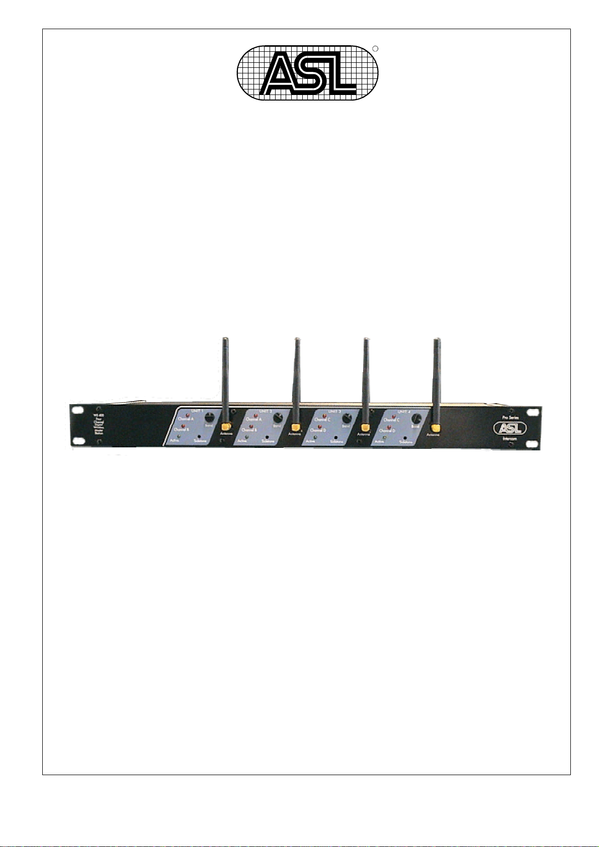
WS 400
FOUR UNIT WIRELESS BASE STATION
CONTENTS
1.0 GENERAL DESCRIPTION..........................................3
2.0 UNPACKING...............................................................3
3.0 INSTALLATION...........................................................3
4.0 FRONT PANEL CONTROLS ......................................4
5.0 REAR PANEL CONNECTORS ...................................6
6.0 SETTING UP A CONNECTION ..................................8
7.0 COMMUNICATION MODES .......................................9
8.0 PRINCIPLES OF OPERATION.................................10
9.0 CABLING..................................................................11
10.0 PARTYLINE TECHNICAL CONCEPT.......................11
11.0 WARRANTY .............................................................11
12.0 TECHNICAL SPECIFICATIONS...............................11
Page 2

User Manual WS 400 / Issue 1 © 2002 ASL Intercom, Utrecht, Holland.
Page 3

1.0 GENERAL DESCRIPTION
The WS 400 is a four unit, wireless base
station housed in a strong steel 19”
housing.
On the front panel four sections of TX/RX
units with channel selectors, antennas and
LED indicators.
Special attention has been paid to the
intelligibility of speech. By applying low
noise/high speed op-amps, a speech
presence filter and a specially developed
amplifier, communication is very
comfortable even in environments with a
very high background noise level.
2.0 UNPACKING
The shipping carton contains the parts
listed below:
· The WS 400
· User manual
· Four antenna’s
· Power cord
If any are missing, contact your dealer.
3.0 INSTALLATION
This WS 400 will form the base station for a
WS 19 or WS 29 beltpack and the interface
for that beltpack to the wired intercom
system. The unit has it’s own mains power
supply and will therefore not be any load to
the wired intercom system.
Adjust the ‘channel select’ switch to match
the selected channel on the beltpack.
After switching on the unit with the power
The unit is designed to be the base station
for the wireless beltpacks WS 19 and WS
29. Each of the four TX/RX units can
maintain a full duplex connection with a
beltpack and have separated XLR
connectors at the rear panel. The interface
to the wired system can be switched as
partyline or 4-wire mode.
ASL has taken great care to ensure this
product reaches you in flawless condition.
After unpacking the unit please inspect for
any physical damage, and retain the
shipping carton and relevant packing
materials for use should the unit need
returning.
If any damage has occurred, please notify
your dealer immediately so that a written
claim can be initiated. Please also refer to
the guarantee section of this manual.
switch at the rear panel, the unit should
have contact with the beltpack(s).
To check this simply push the CALL or
TALK button on the beltpack and the “RX
ACTIVE” LED’s should indicate any activity
of the beltpack.
User Manual WS 400 / Issue 1 © 2002 ASL Intercom, Utrecht, Holland.
Page 4

4.0 FRONT PANEL CONTROLS
1 RX active LED
This LED will be lit when the RX/TX Unit
receives data from an active beltpack.
When the beltpack is talking or sending
a CALL the led will be lit. When a
beltpack is only listening it will not be lit.
2 BELTPACK MODE LED’S
These LED’s will show the setting of the
audio interface. In case of a WS 19, the
top LED, 1 ch. Beltpack (A), will be lit
indicating that a single channel beltpack
is using this connection and that the
audio of that beltpack is routed to the
XLR connectors of channel A.
In case of a WS 29, the bottom LEDs, 2
ch. Beltpack (A+B) or 2 ch. Beltpack
(C+D), will be lit indicating that a dual
channel beltpack is using this connection
and that the audio of that beltpack is
routed to the XLR connectors of channel
A + B or to channel C + D. Please make
sure that a WS 29 is connected to either
channel A + B or to channel C + D.
3 SIDE TONE TRIMMER
This trimmer adjusts the level of your
own voice as you hear it in your headset.
The operating area is between fully
clockwise and minimum level. Adjusting
this signal does not affect the level of
your voice as it is heard by other
stations.
Adjustment procedure
:
Turn down the OWN VOICE volume
trimmer at the side panel of the beltpack.
(counter-clockwise)
Switch on the TALK function of the
beltpack (TALK button).
Talk into the microphone and listen to
your own voice, you might hear a
small delay in the signal.
Now turn down the volume of your
own voice by adjusting the SIDE
TONE trimmer at the base station of
the TX/RX unit to which the beltpack
is connected.
Adjust the trimmer so that the level of
your own voice is as low as possible.
Now turn up the volume of your own
voice by adjusting the OWN VOICE
trimmer to a level that you like.
4 CHANNEL SELECT SWITCH
With this switch the channel is
selected on which the base station will
communicate with the beltpack. The
selected channel must match the
channel set at the beltpack.
5 ANTENNA CONNECTOR
On this connector the supplied
antennas are to be connected.
Please read the section PRINCIPLES
OF OPERATION very carefully to be
sure of optimum performance of your
base station.
User Manual WS 400 / Issue 1 © 2002 ASL Intercom, Utrecht, Holland.
Page 5

5.0 REAR PANEL CONNECTORS
1 INTERFACE MODE SWITCH
This switch determines the mode of the
audio interface and the function of the XLR
connectors 3 and 4.
When the switch is not pushed the XLRs
are both partyline connectors (input and
link) and the beltpacks audio is send to this
partyline. In this mode the base station will
also handle all CALL functions to and from
the wired intercom, and MIC MUTE
functions from the wired intercom.
When this switch is pushed the audio
interface is in 4-wire mode, this means that
the male connector outputs the audio
signal from the beltpack as an
electronically balanced signal, and the
female connector is the electronically
balanced input connector for audio to the
beltpack.
2 OUTPUT LEVEL TRIMMER
This trimmer adjusts the output level of the
audio signal that comes from the beltpack.
3 OUTPUT/LINK CONNECTOR
When the interface is in partyline mode:
This male XLR-3 connector is the link/out
connector and is connected parallel to the
female XLR-3 (4).
When the interface is in 4-wire mode:
This male XLR-3 connector is the
electronically balanced audio signal from
the beltpack.
4 INPUT CONNECTOR
When the interface is in partyline mode:
This female XLR-3 connector is the input
connector and is connected parallel to the
male XLR-3 (3).
When the interface is in 4-wire mode:
This female XLR-3 connector is the
electronically balanced audio signal input
that is sent to the beltpack.
5 INPUT LEVEL TRIMMER
This trimmer adjusts the input level of the
audio signal that is send to the beltpack.
6 SUB-D LINK CONNECTOR
This connector contains all signals that
need to be interchanged when two base
stations are to be used in the same space.
Only use the special cable that ASL-
Intercom supplies as an option.
7 MAINS SWITCH
With this mains switch the unit can be
switched on or off.
8 MAINS INPUT
This mains input accepts 90 – 240 V AC,
at 50 – 60 Hz. This part also holds the fuse
and a spare fuse on the bottom part. The
fuse needs to be 1,25 Amp of the slow
blow type.
User Manual WS 400 / Issue 1 © 2002 ASL Intercom, Utrecht, Holland.
Page 6

6.0 SETTING UP A CONNECTION
6.1 BASE STATION SETTINGS
A) The base station must be set up
properly according to the user manual.
Give each TX/RX unit of the base station
its own channel by rotating the Channel
select switch.
Try to avoid concurrent channels to be
physically next to each other, e.g. in a
setting of two WS 400’s try to set them in
this order : 2, 4, 6, 8, 1, 3, 5, 7
If you use a WS 200 with only two
beltpacks use channels 1 and 6.
B) Connect the base station to the
partyline intercom or 4 wire system and
make sure the interface mode switch at the
back is set accordingly.
C) turn the sidetone trimmers counter
clockwise.
6.2 BELTPACK SETTINGS
Select with the ‘Channel select’ switch at
the rear of the beltpack the channel to
match the WS 200 or WS 400 setting.
Connect a headset to the beltpack and
insert fully charged batteries.
When the beltpack is switched on then a
single short tone should be heard and both
LEDs on the front panel of the unit will
flash for half a second. This indicates that
the beltpack is functioning okay.
If you press the CALL or TALK button the
LEDs on the front panel will be lit and the
corresponding TX/RX unit of the base
station will show a green ACTIVE LED.
This means that the beltpack has
connection with the base station.
6.3 SIDETONE ADJUSTMENT
Turn down the OWN VOICE volume
trimmer at the side panel of the
beltpack. (counter-clockwise)
Switch on the TALK function of the
beltpack (TALK button).
Talk in the microphone and listen to
your own voice, you might hear a small
delay in the signal.
Now turn down the volume of your own
voice by adjusting the SIDE TONE
trimmer at the base station of the TX/RX
unit to which the beltpack is connected.
Adjust the trimmer so that the level of
your own voice is as low as possible.
Now turn up the volume of your own
voice by adjusting the OWN VOICE
trimmer to a level that you like.
6.4 FULL DUPLEX AND HALF DUPLEX
USE
Although the system is designed to be
used in full duplex use, there is a
possibility to use the system in half
duplex mode, too.
Half duplex allows more than 1 beltpack
on the same frequency and therefore,
on one TX/RX unit of a base station.
Every beltpack will be able to listen to
the base station, but only one of the
listening beltpacks can talk at a time
and have a full duplex connection. As
long as one of the beltpacks has a full
duplex connection, the other beltpacks
will not be able to CALL or TALK.
In this mode it is useful not to adjust the
sidetone trimmer on the base station,
turn it fully counter clockwise.
Read the next chapter about
communication modes carefully.
User Manual WS 400 / Issue 1 © 2002 ASL Intercom, Utrecht, Holland.
Page 7

7.0 COMMUNICATION MODES
This system is designed to offer a
maximum of 8 wireless, full duplex,
beltpacks. Each beltpack may be a
single channel beltpack WS 19 or a dual
channel beltpack WS 29.
Each beltpack needs to be assigned to
a unique channel. On this channel the
communication between the beltpack
and the base station will take place. If
another base station is set to the same
channel the communication will be
garbled and will result in a none
functioning connection.
The base station will automatically
select the right mode for a WS 19 or
WS 29 beltpack. A WS 19 beltpack will
always be connected to one channel at
the base station, a WS 29 beltpack will
be assigned to two channels on the
base station.
7.1 FULL DUPLEX
A connection of one WS 19 on e.g.
Channel 1 will be accomplished by
selecting channel 1 on the beltpack, and
channel 1 on TX/RX unit 1 of the base
station. The connection is a dedicated
and full duplex connection.
The sidetone needs to be adjusted at
the front of the base station and the
user of the beltpack can adjust his own
voice at the beltpack with the
designated trimmer.
7.2 HALF DUPLEX
A connection of several WS 19
beltpacks on e.g. Channel 1 to a TX/RX
unit of a base station (also channel 1
selected) results in a half duplex
connection.
This means that all the beltpacks can
listen to the same TX/RX unit of the
base station. Only one beltpack can
TALK to the base station.
User Manual WS 400 / Issue 1 © 2002 ASL Intercom, Utrecht, Holland.
The beltpack that selects TALK mode
will occupy the connection, and the
TALK function of all other listening
beltpacks is disabled.
The same applies for sending CALL
signals, only one beltpack may send a
call signal but all of them will receive it.
There is one major drawback to half
duplex mode, due to the principle of the
partyline concept.
In case of a very good adjusted
sidetone trimmer at the base station this
effect will be noticed :
When 2 or more beltpacks are using the
same TX/RX unit of a base station
(listening to the same signal), and one
of the beltpacks is talking to the base
station, the listening beltpack will not be
able to hear the talking beltpack.
This effect is caused by the adjusted
sidetone that prevents the microphone
signal of a beltpack to be heard by
himself, and therefore, also heard by
other beltpacks on the same TX/RX
unit.
To solve this, the sidetone trimmer of
the TX/RX unit should be turned fully
counter clockwise.
This has one disadvantage too, if a
beltpack talks to the base he will hear
his own voice in his headset with a
delay of 24 ms. The other listening
beltpacks will not notice this delay.
By adjusting the OWN VOICE trimmer
at the beltpack the effect can be made
less.
Page 8

8.0 PRINCIPLES OF OPERATION
The wireless system uses the 2,4 GHz
band, which is freely available for WLAN
(Wireless Local Area Networks).
The ASL-intercom system divides the
available bandwidth into 16 overlapping
parts, 8 of them are being used as upload
channel from the beltpacks and the other 8
are being used as download channel to the
beltpacks.
With the channel select switch you actually
select an upload and download channel
pair to be used for that beltpack. On every
channel
only one
section of a base station
may be working.
More than one beltpack on the same
channel is possible as described in section
8.2.
8.1 HF FREQUENCIES
Due to the fact of the very high frequency
the user must take precautions in
placement.
The frequency of 2,4 GHz is known to
have difficulty in penetrating concrete
walls, steel walls and other obstructions.
Behind obstructions like these an “HF
shadow” may occur where no
communication is possible.
Another point of interest is that this
frequency may have reflections more
easily than lower frequencies. You might
experience a dropout on a very specific
spot in a building, moving the beltpack only
a few inches can be enough to solve the
problem.
Because of the use of the WLAN
frequencies the units might experience
interference from units like mobile
telephones with bluetooth, computers with
bluetooth or WLAN cards.
Try to change channels if you experience
problems with these.
8.2 ANTENNA’S
Another point of interest is placing the
unit in a 19” rack. The user needs to pay
special attention to the placement of the
antenna. The antenna of the base
station needs to have a “line of sight” to
the antenna of the beltpack.
All objects that are within that path will
make the connection less reliable.
This starts with the 19” rack itself, the
maximum available distance behind the
rack will be less than in front of the rack.
The base stations WS 200 and WS 400
are available in versions with the
antenna connectors at the front or at the
rear panel. Choose whichever version is
the most convenient to you.
All base stations are equipped with SMA
connectors, female at the base station
and male at the antenna.
If the antennas are not to be directly
connected to the front or the rear panel,
the user must take care of the right type
of cable to be used; it needs to be of the
50 ohm type. The 2,4GHz frequency
experiences a big loss in any cable, e.g.
a RG58 cable of 3 meters has a loss of
3 dB, so make sure that your cable is
suited for this frequency, and the cable
is as short as possible.
Make the cables in lengths that can be
divided by 12cm. e.g. 24cm, 48cm,
120cm, 240cm.
User Manual WS 400 / Issue 1 © 2002 ASL Intercom, Utrecht, Holland.
Page 9

9.0 CABLING
For the PRO Series Intercom system the interconnecting cables are of the shielded two-conductor microphone cable type and the
intercom line connectors are of the XLR-3 type. Audio and Call signals are on XLR pin 3, DC power is on XLR pin 2. XLR pin 1 is
connected to the shield of the cable, which functions as the common return for audio and power.
Since the audio signal is transferred in an
unbalanced
« way, certain rules have to be obeyed when installing the cables of an
intercom network. This is to avoid earth loops and to minimize power loss and the possible effect of electromagnetic fields.
These rules are:
• Use high quality (multipair) cable.
For interconnecting user stations, power supplies and
accessories in an ASL Intercom network, use high
quality shielded two-conductor (minimum 2x 0.30
mm2) microphone cable only.
In case of a multi channel intercom network, use high
quality microphone 'multipair' cable only, each pair
consisting of two conductors (minimum 2x 0.15 mm2)
with separate shield. Multipair cable should also have
an overall shield.
• Use flexible cables.
Use flexible single and multipair microphone cable
instead of cable with solid cores, especially when the
cable is subjected to bending during operation or
installation.
• Separate cable screen to XLR pin 1.
The screen of each separate microphone cable and/or
the screen of each single pair in a multipair cable,
should be connected to pin 1 of each XLR-3
connector. Do not connect this cable screen to the
metal housing of the connector or to metal wall boxes
(outlets).
See page 12 for Earthing Concept.
• Cable trunks, connection boxes and overall
multipair cable screen to clean earth.
Metal cable trunks, metal connection boxes and
overall multipair cable screen should be interconnected and, at one point (the 'central earthing
point') in the intercom network only, be connected to a
clean safety earth.
See page 12 for Earthing Concept.
• Keep metal connection boxes and cable trunks
isolated from other metal parts.
Metal housings for intercom cables and connectors
should be mounted in such a way that they are
isolated from other metal cable and connector
housings and from any other metal construction parts.
• Keep cables parallel as much as possible
When two (multi channel) units in a network are
connected by more than one cable, make sure that
these cables are parallel to each other over the whole
distance between those units. When using multipair
cable, parallelism is ensured in the best possible way.
• Avoid closed loops.
Always avoid that cables are making a loop. So-called
'ring intercom' should not physically be cabled as a
ring. All cable routes should have a 'star' configuration,
with the central earthing point (usually close to the
power supply position) as the centre of the star.
• Keep cables away from electromagnetic sources.
Keep intercom cables away from high-energy cables,
e.g. 110/220/380V mains power or dimmer controlled
feeds for spotlights.
Intercom cables should cross high-energy cables at an
angle of 90° only.
Intercom cables should never be in the same trunking
as energy cables.
• Place power supplies in a central position.
In order to avoid unacceptable power losses, place the
power supplies as close as possible to where most
power consumption occurs or, in other words, most
user stations are placed.
• Connect ASL power supply to a 'clean' mains
outlet.
The ASL power supply may be connected to the mains
power outlet to which other audio equipment is
connected. Avoid using mains outlets, which also
power dimmer controlled lighting systems.
In case of more complex installations, don't hesitate to
contact us. Please send us a block diagram of the
planned network with a list of all user stations and their
positions, and we are happy to advise you on cabling
layout.
«
See Party Line, Technical Concept
User Manual WS 400 / Issue 1 © 2002 ASL Intercom, Utrecht, Holland.
Page 10

10.0 PARTY LINE, TECHNICAL CONCEPT 12.0 TECHNICAL SPECIFICATIONS WS 400
ASL's WIRELESS Series offers a complete two way
('full duplex') communication system.
Users of the system are connected via a 'party line'
base station (with built-in power supply); beltpacks and
power supplies are interconnected via standard
microphone cable. One wire is used as an audio line,
one as a power line and the screen of the cable
functions as earth/return.
Current drive is used for signal transfer. Each station
utilizes a current amplifier to amplify the microphone
signal and place it on the common audio line where,
due to the constant line impedance (situated in the
power supply between XLR pin 3 and 1), a signal
voltage is developed which can be further amplified and
sent to the headphones.
This principle has three advantages:
- the use of a single audio line allows several stations
to talk and listen simultaneously.
- due to the high bridging impedance offered by each
station, the number of stations 'on line' has no
influence on the level of the communications signal.
- power and audio to the intercom stations use the
same cable.
The Call signal is also sent as a current on the audio
line. It develops a DC potential over the line impedance,
which will be sensed by each station and interpreted as
a Call signal.
11.0 WARRANTY
ASL Intercom warrants this unit to the original end-user
purchaser against defects in workmanship and
materials in its manufacture for a period of two years
from date of shipment to the end-user.
Faults arising from misuse, unauthorized modifications
or accidents are not covered by this warranty. If the unit
is faulty, it should be sent in its original packing to the
supplier or your local ASL dealer, with shipping prepaid.
A note must be included stating the faults found and a
copy of the original suppliers invoice.
THIS PRODUCT WAS DESIGNED, DEVELOPED AND
MANUFACTURED BY:
ASL Intercom
UTRECHT, HOLLAND.
http://www.asl-inter.com
MAINS POWER
Mains power 90 – 240 V AC
50 – 60 Hz
Fuse 1250 mAT
Max Consumption 25 Watt
4-WIRE MODE:
INPUT AMPLIFIER
input impedance min. 10Kohm
input level +30 to - 10 dBm
frequency response 60Hz - 20KHz (-3dB)
OUTPUT AMPLIFIER
output impedance < 25 ohms
maximum load 600 ohms
max. output level +20 to -20 dBm
frequency response 40 Hz - 20 KHz
PARTYLINE MODE:
INTERCOM LINE DRIVER
Max. output current 3mA rms
output impedance > 150 Kohm
SIDETONE
rejection min. 20 dB (20Hz - 20 KHz)
audio line level -18dBm (max. 0dBm)
signal-to-noise 70dB
station bridging impedance >150 Kohm
DIMENSIONS AND WEIGHT
width 480 mm
height 44 mm
depth 165 mm
weight 2300 grams
GENERAL SYSTEM SPECIFICATIONS
dynamic range 70 dB
Transceiver frequency 2400 – 2483.5 MHz
Transmit Power 10 mW E.I.R.P.
Number of channels 8
Channel separation 7 MHz
Note : 0dBu = 775 mV into open circuit
ASL reserves the right to alter specifications without further notice.
User Manual WS 400 / Issue 1 © 2002 ASL Intercom, Utrecht, Holland.
Page 11

User Manual WS 400 / Issue 1 © 2002 ASL Intercom, Utrecht, Holland.
 Loading...