

Page 1
PS 130
SINGLE CHANNEL SPEAKER STATION
USER MANUAL
User Manual PS 130 / Issue 2010 / © ASL Intercom BV
Page 2

2
CONTENT OF THIS USER MANUAL
1.0 GENERAL DESCRIPTION ......................................................................................................................................... 3
2.0 UNPACKING ........................................................................................................................................................... 3
3.0 INSTALLATION ....................................................................................................................................................... 3
4.0 FRONTPANEL CONTROLS & CONNECTORS ........................................................................................................... 4
5.0 SIDE PANEL CONNECTORS .................................................................................................................................... 5
6.0 INTERNAL CONTROLS ............................................................................................................................................ 6
7.0 PARTY LINE, TECHNICAL CONCEPT ........................................................................................................................ 6
8.0 WARRANTY ............................................................................................................................................................ 6
9.0 CABLING ................................................................................................................................................................ 7
10.0 TECHNICAL SPECIFICATIONS ................................................................................................................................. 8
11.0 PS 130 BLOCK DIAGRAM ....................................................................................................................................... 9
12.0 SYSTEM CONFIGURATION ................................................................................................................................... 10
13.0 EARTHING CONCEPT ........................................................................................................................................... 11
User Manual PS 130 / Issue 2010 / © ASL Intercom BV
Page 3

3
1.0 GENERAL DESCRIPTION
The PS 130 is a single channel speaker station
designed for use in both portable and fixed ASL
intercom systems. It incorporates a loudspeaker
and a gooseneck microphone and provides full
duplex communications.
The PS 130 RM model has a small built-in
electret microphone.
At the front panel are a Volume (listen level)
Control, a TALK and CALL button with LED
indicators, and trimmers for side tone, speaker
attenuation and buzzer volume.
The unit is equipped with a limiter for the
gooseneck microphone, allowing the user to
speak close into the microphone without giving
rise to overload and distortion.
Loudspeaker dimming is automatic when the
microphone is active. Private conversation may
be carried out via the headset connector with a
headset or telephone handset. When a headset is
connected, both the gooseneck microphone and
speaker are disabled automatically.
2.0 UNPACKING
The shipping carton contains the parts below:
* The PS 130
* User manual
If any are missing, contact your dealer.
ASL has taken great care to ensure this product
reaches you in flawless condition.
3.0 INSTALLATION
This PS 130 will form part of an existing or new
intercom system, and connection to it is
straightforward. There are no separate power
connections or batteries to install, as the
necessary DC voltages are derived from a master
station or a separate power supply, via the
intercom connection cable.
To connect the PS 130 to the intercom system,
use professional flexible microphone cable with 2
wires and 1 shield only. Connect the system
Special attention has been paid to the intelligibility
of speech. By applying low noise/high speed opamps, a speech presence filter and a specially
developed high power bridged headphone
amplifier, communication is very comfortable even
in environments with high back-ground noise
level. There is a separate amplifier for the
loudspeaker.
The unique ASL CALL system provides both a
flashing red LED and a very characteristic sound
signal (the buzzer). Smooth operation is
guaranteed with the CALL button. Only a slight
touch makes the red LED flash, whilst holding the
button for two seconds activates the CALL sound
signal. The volume of the buzzer can be adjusted
at the front panel.
Fully electronic switching increases reliability and
allows for :
- 'soft' microphone ON switching, latching or
momentary
- remote Mic Mute facility
- automatic speaker attenuation (adjustable),
when the microphone is activated
After unpacking the unit please inspect for any
physical damage to the unit, and retain the
shipping carton and relevant packing materials for
use should the unit need returning.
If any damage has occurred, please notify your
dealer immediately so that a written claim can be
initiated. Please also refer to the warranty section
of this manual.
intercom cable to the LINE connector on the side
panel. Finally, when private conversation is
desired, connect a headset plug into the XLR-4
HEADSET connector on the front panel.
The PS 130 is fully protected against mis-wiring
(reverse power) or short circuit in the interconnect
cables.
A special kit is available for mounting the PS 130
in a 19" rack, taking 2RU of rack space.
User Manual PS 130 / Issue 2010 / © ASL Intercom BV
Page 4
4
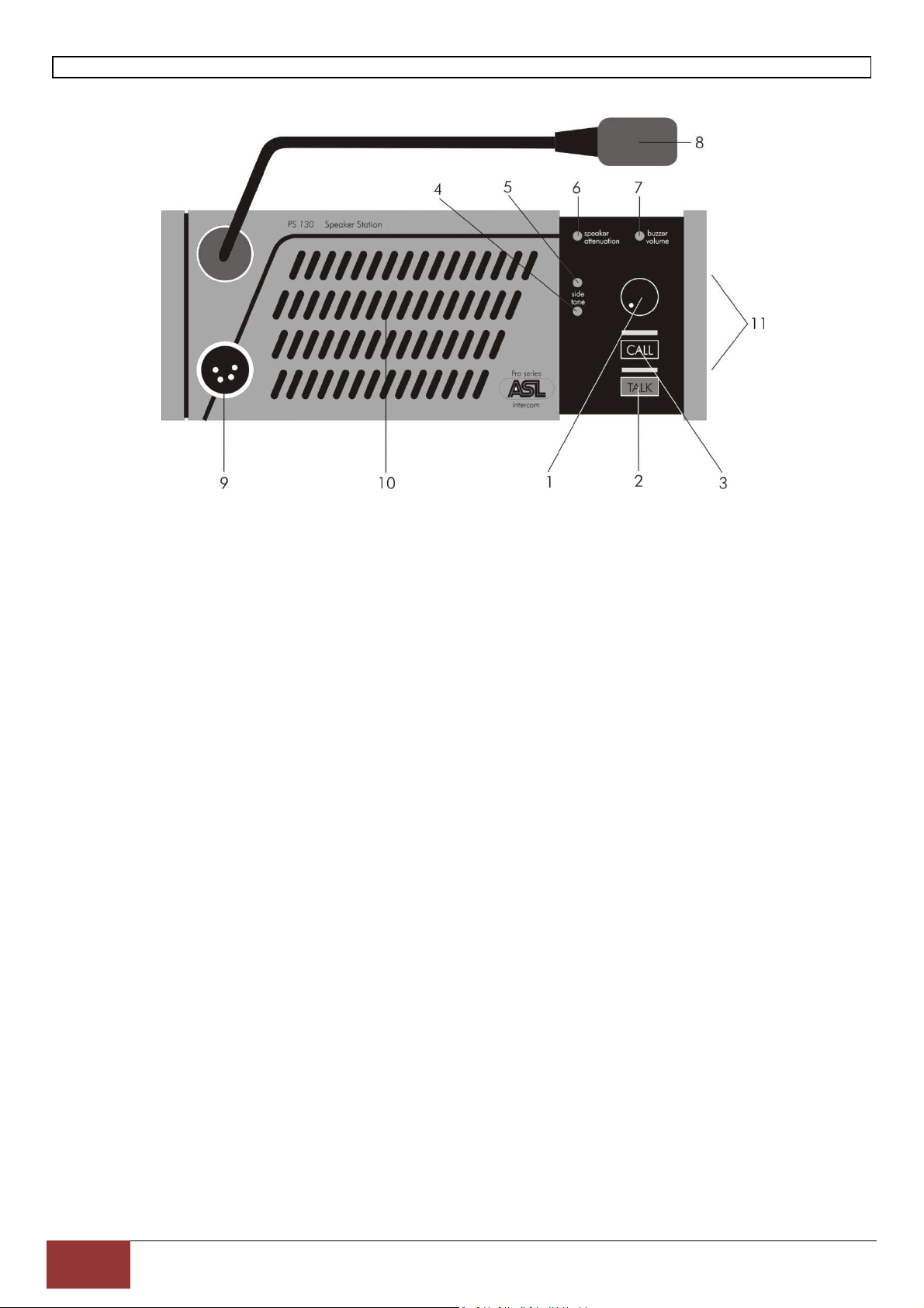
4.0 FRONTPANEL CONTROLS & CONNECTORS
1 VOLUME control knob
This knob adjusts the listen level for the
headset and the loudspeaker.
2 TALK button
This push button activates the gooseneck
or headset microphone, the large green
LED indicates if the microphone is
switched on.
Latched switching:
When a TALK button is pressed quickly,
the microphone will be switched on, and is
electronically latched. When pressed
again, the microphone will be switched off.
When the microphone is latched on, it can
be muted by a Mic Mute from a PRO
Series master station or separate power
supply.
Momentary switching:
When a TALK button is pushed and held,
the microphone switches on and when
released switches off.
3 CALL button
This push button activates the call system.
A momentary push will send a call signal
to all stations connected to the intercom
channel and the call LEDS will start
flashing. Push and hold the button for 2
seconds will activate the call buzzer, if not
muted. After the CALL button is released
the LEDS will continue to flash for further 2
seconds.
4 SIDE TONE LEVEL trimmer
This trimmer controls the level of your own
voice as you hear it in the speaker or in
the headset. It prevents the speaker from
feeding back into the microphone.
5 SIDE TONE HI trimmer
The HI trimmer controls the rejection in the
high frequency range. The trimmer
compensates the capacity of the
interconnecting cables and prevents the
loudspeaker from feeding back into the
microphone (unit feedback).
Adjustment procedure for both side tone
trimmers, first 4 and then 5 :
- set trimmer in start position: fully
clockwise
- switch off the microphones of all
connected (speaker) stations
- switch on the headset microphone of
this PS 130
- turn up the volume
- speak into the headset microphone
- adjust the listen level by turning the
side tone trimmer
For optimum result, repeat the above
mentioned procedure for trimmer 4 & 5.
The operating area is between fully
clockwise and minimum level. Adjusting
the side tone does not affect the level of
your voice as it is heard by other stations.
User Manual PS 130 / Issue 2010 / © ASL Intercom BV
Page 5
5
6 SPEAKER ATTENUATOR trimmer
This trimmer adjusts the extent to which
the speaker is automatically dimmed when
the gooseneck microphone is switched on.
It prevents :
- unit feedback if side tone rejection is not
sufficient
- system feedback or a 'hollow' sound
when the microphones of other speaker
stations on the same
channel are activated simultaneously
Adjustment procedure :
- switch off the TALK buttons
- inject an audio signal on the intercom
channel
- turn up volume
- activate microphone and adjust the
desired degree of attenuation
The speaker attenuator has no effect
when a headset is used.
7 BUZZER VOLUME trimmer
This trimmer adjusts the volume of the
internal buzzer, which is located behind
the front panel.
The buzzer is activated if the CALL button
of the PS 130 is pushed (or a CALL button
of any other station on the channel to
which the PS 130 is connected) longer
than 2 seconds, provided the buzzers are
not muted (buzzers are muted on the
master station or a separate power
supply).
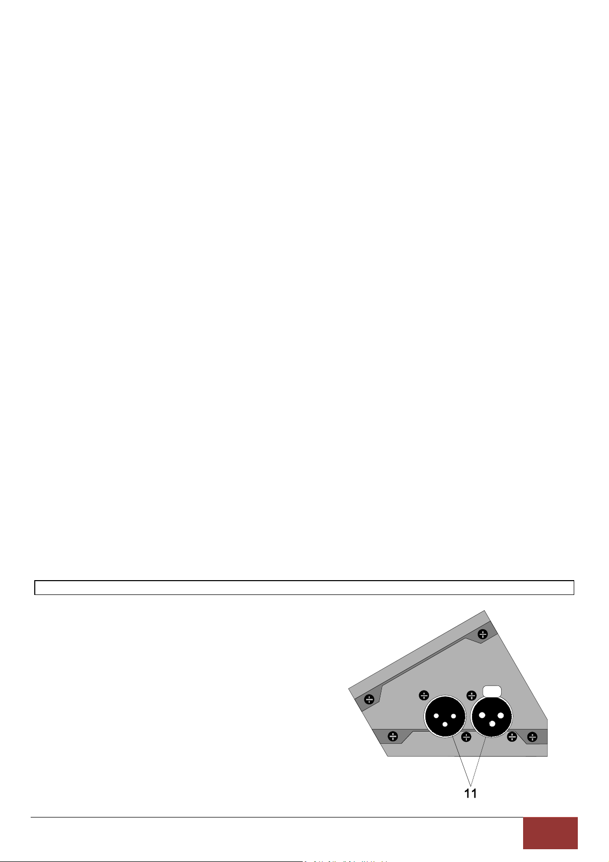
5.0 SIDE PANEL CONNECTORS
11 LINE connectors
These connectors are for connecting the
PS 130 to the intercom system.
XLR-3 pin assignments :
1. 0 V /ground shield
2. +30V power wire
3. audio wire
The female connector is for input,
the male connector for extending
the intercom line to other stations.
8 GOOSENECK MICROPHONE
The PS 130 is equipped with a high quality
electret noise canceling microphone. A
limiter prevents the microphone
preamplifier from clipping when speaking
close into the microphone.
9 HEADSET connector
An XLR-4 type connector for the
connection of a local headset when private
conversation is desired. The headset must
have a can impedance of 200 ohms
minimum, or have two cans in parallel
each 400 ohms minimum. The microphone
may be of the dynamic or electret type.
XLR-4 pin assignments :
1. Shield mic. (GND)
2. mic. +
3. phones +
4. phones
When connecting a headset, the speaker
and gooseneck microphone are disabled
automatically.
10 LOUDSPEAKER
A high quality loudspeaker driven by a 2.9
Watt amplifier.
User Manual PS 130 / Issue 2010 / © ASL Intercom BV
Page 6

6
6.0 INTERNAL CONTROLS
Inside the unit there are two trimmers to adjust
the mic gain of the gooseneck microphone and
the headset microphone separately. The trimmers
are located on the PC board.
They can be reached as follows :
- remove the screws of the bottom plate
7.0 PARTY LINE, TECHNICAL CONCEPT
ASL’s analog intercom offers a complete two way
('full duplex') communications system. Users of
the system are connected via a 'party line'.
Master stations (with built-in power supply),
beltpacks, speaker stations and power supplies
are interconnected via standard microphone
cable. One wire is used as an audio line, one as a
power line and the screen of the cable functions
as earth/return.
Current drive is used for signal transfer. Each
station utilizes a current amplifier to amplify the
microphone signal and place it on the common
audio line where, due to the constant line
impedance (situated in the power supply between
XLR pin 3 and 1), a signal voltage is developed
8.0 WARRANTY
This unit is warranted by ASL Intercom to the
original end-user purchaser against defects in
workmanship and materials in it's manufacture for
a period of one year from date of shipment to the
end-user.
- slide the plate to one side and take it out
- take away the plastic isolation plate
The two trimmers are labeled :
GOOSE for the gooseneck microphone
HEADS for the headset microphone
which can be further amplified and sent to
headphones or loudspeakers.
This principle has three advantages:
- the use of a single audio line allows several
stations to talk and listen simultaneously
- due to the high bridging impedance offered by
each station, the number of stations 'on line' has
no influence on the level of the communications
signal
-power and audio to the intercom stations use the
same cable.
The Call signal is also sent as a current on the
audio line. It develops a DC potential over the line
impedance which will be sensed by each station
and interpreted as a Call signal.
Faults arising from misuse, unauthorized
modifications or accidents are not covered by this
warranty. If the unit is faulty it should be sent in
it's original packing, to the supplier or your local
ASL dealer, with shipping prepaid. A note must
be included stating the faults found and a copy of
the original suppliers invoice.
User Manual PS 130 / Issue 2010 / © ASL Intercom BV
[Type the company name]
Page 7

7
9.0 CABLING
The ASL analog intercom stations, power supplies, interfaces and accessories are interconnected by
cables of the shielded two-conductor microphone cable type. The intercom line connectors are of the XLR3 type. Audio and Call signals are on XLR pin 3, DC power is on XLR pin 2. XLR pin 1 is connected to the
shield of the cable which functions as the common return for audio and power.
Since the audio signal is transferred in an unbalanced way (see Party Line, Technical Concept), certain
rules have to be obeyed when installing the cabling of an intercom network. This is to avoid earth loops and
to minimize power loss and the possible effect of electromagnetic fields.
Use high quality cable
Use high quality microphone cable (shielded two
conductor cable, minimum 2x 0.30 mm2).
In case of a multi channel intercom network, use
high quality microphone 'multi-pair' cable only,
each pair consisting of two conductors (minimum
2x 0.15 mm2) with separate shield. Multi-pair
cable should have an overall shield as well.
Use flexible cable
Use flexible single and multi-pair microphone
cable instead of cable with solid cores, especially
when the cable is subjected to bending during
operation or installation.
Cable screens to XLR pin 1
The screen of each separate microphone cable
and/or the screen of each single pair in a multipair cable, should be connected to pin 1 of each
XLR-3 connector. Do not connect this cable
screen to the metal housing of the connector or to
metal wall boxes (outlets). See Earthing Concept.
Connect cable trunks, connection
boxes and overall multi-pair cable
screens to clean earth
Metal cable trunks, metal connection boxes and
overall multi-pair cable screens should be
interconnected and, at one point (the 'central
earth point') in the intercom network only, be
connected to a clean earth or a safety earth (see
Party Line, Earthing Concept).
Keep metal connection boxes and
trunks isolated from other metal parts
Metal housings for intercom cables and
connectors should be mounted in such a way that
they are isolated from other metal cable and
connector housings and from any other metal
construction parts.
Keep cables parallel as much as
possible
When two (multi channel) units in a network are
connected by more than one cable, make sure
that these cables are parallel to each other over
the whole distance between those units. When
using multi-pair cable, parallelism is ensured in
the best possible way.
Avoid closed loops
Always avoid that cables are making a loop. Socalled 'ring intercom' should not physically be
cabled as a ring. All cable routes should have a
'star' configuration, with the central earth point
(usually close to the power supply position) as the
centre of the star.
Keep cables away from
electromagnetic sources
Keep intercom cables away from high energy
cables, e.g. 115/230/400V mains power or
dimmer controlled feeds for spotlights. Intercom
cables should cross high energy cables at an
angle of 90º only. Intercom cables should never
be in the same trunks as energy cables.
Place power supply in a central
position
In order to avoid unacceptable power losses,
place the master station or the power supply as
close as possible to where most power
consumption occurs, in other words most user
stations are placed.
Connect ASL power supplies to a
'clean' mains outlet
Master stations or power supplies may be
connected to the mains outlet to which other
audio equipment is connected. Avoid using mains
outlets which also power dimmer controlled
lighting systems.
In case of more complex installations, don't hesitate to contact us. Please send a block diagram of the
planned network with a list of all user stations and their positions, and we are happy to advise you on
cabling lay out.
User Manual PS 130 / Issue 2010 / © ASL Intercom BV
Page 8

8
10.0 TECHNICAL SPECIFICATIONS
System
Dynamic range: 80 dB ( 1 kHz, THD < 1%)
Call signal: (send): +2.8 mA
Call signal threshold (receive): +2.4V DC
Supply voltage: +30V DC (12V to 32V)
Power interrupt time (Mic Mute): 0.1 sec
Intercom Line
Impedance: 350 Ohms (1 kHz), 2.2 kOhms (DC)
Audio level: nom. -18 dBu, max. +4 dBu
Microphone Pre-amps
Headset mic impedance: 200 Ohms
Gain: 40 – 60 dB (adjustable internally, separately
for the headset mic and the gooseneck mic)
Presence filter: +6 dB @ 5 kHz
Frequency response: 200 Hz – 15 kHz (-3dB)
Power to electret mic: +9V DC
Limiter range (gooseneck mic): 30 dB
Headphone Driver Amp
Max. output level: 14 Vrms (@ 200 Ohms
Max. output power: 1 Wrms @ 400 Ohms
ASL reserves the right to alter specifications without prior notice.
DESIGNED AND MANUFACTURED BY:
ASL Intercom B.V.
Zonnebaan 42
3542 EG Utrecht
The Netherlands
Phone +31 (0)30 2411901
Fax: +31 (0)30 2667373
E-mail: info@asl-inter.com
www.asl-inter.com
Web:
Speaker Driver Amp
Speaker impedance: 25 Ohms
Max. output power: 2.9 Wrms
Side Tone
Rejection: 0 - 30 dB adjustable
Buzzer
Max. SPL: 100 dBA
PS 130 Power Consumption
Current (at 30V DC):
- 35 mA quiescent
- 70 mA signaling
- 190 mA at max. output + signaling
PS 130 Dimensions & Weight
Width 230 mm
Height 88 mm
Depth 42/48 mm sloping
Weight 1.1 Kg
Note: 0 dBu = 775 mV into open circuit
User Manual PS 130 / Issue 2010 / © ASL Intercom BV
Page 9

9
11.0 PS 130 BLOCK DIAGRAM
SPEAKER
CALL-LED
SPEAKER AMPLIFIER
SPEAKER AMP AUTOMATICALLY
SWITCHED OFF WHEN HEADSET
IS PLUGGED IN.
LISTEN VOLUME
BUFFER
LINE
XLR pin 3 A
U power
XLR pin 2 A
CURRENT SOURCE
POWER AMPLIFIER
SIDETONE ADJUSTMENT
POWER AMPLIFIER
LED
CONTROLL
BUZZER VOLUME
MULTI-
VIBRATOR
CALL-LED
DELAY
COMPARATOR
BUZZER
GENERATOR
BUZZER
DELAY
ISM-MIC. MUTE
PS MIC. MUTE
ELECTRONIC
TALK-SWITCH
HEADSET MIC GAIN
HEADSET MIC
TALK LED
TALK SWITCH
MIC-PREAMP
GOOSENECK MIC GAIN
GOOSENECK AUTOMATICALLY
GOOSENECK MIC
AUDIO FILTER
LINE
SWITCHED OFF WHEN HEADSET
IS PLUGGED IN.
CALL SWITCH CURRENT SOURCE
User Manual PS 130 / Issue 2010 / © ASL Intercom BV
Page 10

10
12.0 SYSTEM CONFIGURATION
A
User Manual PS 130 / Issue 2010 / © ASL Intercom BV
B
Page 11

11
13.0 EARTHING CONCEPT
User Manual PS 130 / Issue 2010 / © ASL Intercom BV
 Loading...