

Page 1
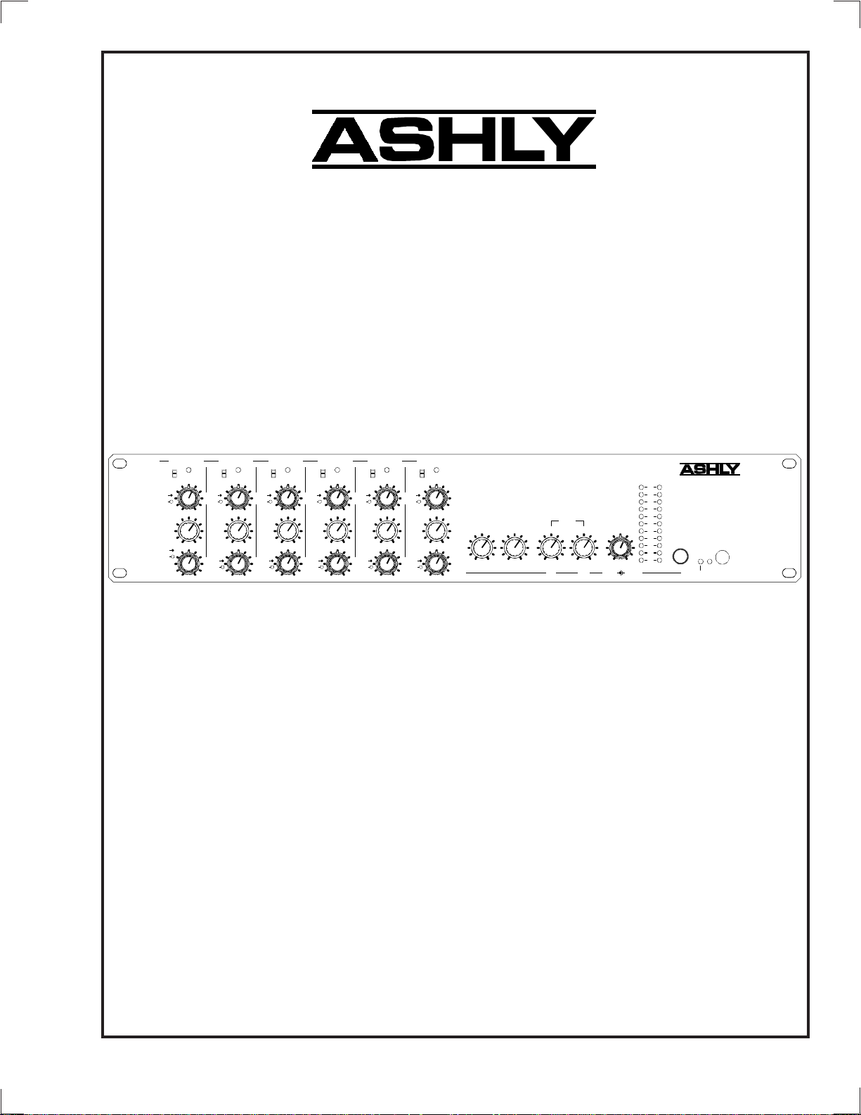
MX-406
Stereo
Microphone/Line
Mixer
Operating Manual
Treble
Bass
-60
-40
-20
Input
(dB)
Aux
Level
Pan
Channel 1
0
-12 +12
5
4
3
1
010
Clip
0
Treble
5
6
4
7
9
010
614
7
8
RL
Bass
Level
-60
-40
-20
Input
(dB)
Aux
Pan
Channel 3
-12 +12
3
1
Channel 2
-60
Clip
-40
-20
Input
(dB)
Treble
Bass
-12 +12
6
3
7
Aux
9
1
614
7
Level
8
Pan
RL
Clip
0
Treble
5
6
4
7
9
010
614
7
8
RL
Bass
Level
-60
-40
-20
Input
(dB)
Aux
Pan
Channel 4
-12 +12
3
1
Clip
0
Treble
5
6
4
7
9
010
614
7
8
RL
Bass
Level
-60
-40
-20
Input
(dB)
Aux
Pan
Channel 5
-12 +12
3
1
Clip
0
Treble
5
6
4
7
9
010
614
7
8
RL
Bass
Level
Pan
Channel 6
-60
-40
-20
Input
(dB)
3
Aux
-12 +12
1
Clip
0
5
6
4
7
8
9
010
614
7
8
RL
Stereo
Aux In put
5
4
3
2
1
010
6
7
9
Aux Master
Output
5
64
010
7
9
010
5
Stereo
Outputs
614
9
5
64
7
8
9
010
RightLeft
Mono/Phones
Output
5
4
1
10
0
Phones
Mono
MX-406
-L- -R-
Stereo
Clip
Six Ch annel
+6
Mic/L ine Mixer
+3
0
-3
-6
-9
6
Stereo
-12
7
Headphones
-15
-18
9
-21
Output
VU
Phantom
On
Power
ASHLY AUDIO INC.
847 Holt Road Webster, NY 14580-9103 Phone: (585) 872-0010
Toll-Free: (800) 828-6308 Fax: (585) 872-0739
www.ashly.com
Page 2

Operating Manual -MX-406 Ster eo Microphone/Line Mixer
Table Of Contents
1 INTRODUCTION . . . . . . . . . . . . . . . . . . . . . . . . . . . . . . . . . . . . . . . . . . . . . . . . . . . . . . . 3
2 UNPACKING . . . . . . . . . . . . . . . . . . . . . . . . . . . . . . . . . . . . . . . . . . . . . . . . . . . . . . . . . . . . 3
3 AC POWER REQUIREMENTS . . . . . . . . . . . . . . . . . . . . . . . . . . . . . . . . . . . . . . . . . . . 3
4 FRONT PANEL CONTROLS . . . . . . . . . . . . . . . . . . . . . . . . . . . . . . . . . . . . . . . . . . . . 4
5 CONNECTORS AND CABLES . . . . . . . . . . . . . . . . . . . . . . . . . . . . . . . . . . . . . . . . . . 6
6 REAR PANEL FEATURES . . . . . . . . . . . . . . . . . . . . . . . . . . . . . . . . . . . . . . . . . . . . . . 6
7 TYPICAL APPLICATIONS . . . . . . . . . . . . . . . . . . . . . . . . . . . . . . . . . . . . . . . . . . . . . . 8
7.1 Small Sound Reinforcement System . . . . . . . . . . . . . . . . . . . . . . . . . . . . . . . . . . . . 8
7.2 Meeting Room, Board Room, or Church Mixer Using Remote Control . . . . . . 9
8 TROUBLESHOOTING TIPS . . . . . . . . . . . . . . . . . . . . . . . . . . . . . . . . . . . . . . . . . . . . . 9
8.1 No Sound . . . . . . . . . . . . . . . . . . . . . . . . . . . . . . . . . . . . . . . . . . . . . . . . . . . . . . . . . . . . 9
8.2 Distorted Sound . . . . . . . . . . . . . . . . . . . . . . . . . . . . . . . . . . . . . . . . . . . . . . . . . . . . . .9
8.3 Excessive Noise . . . . . . . . . . . . . . . . . . . . . . . . . . . . . . . . . . . . . . . . . . . . . . . . . . . . . 10
8.4 Excessive Hum . . . . . . . . . . . . . . . . . . . . . . . . . . . . . . . . . . . . . . . . . . . . . . . . . . . . . . 10
9 DIMENSIONS . . . . . . . . . . . . . . . . . . . . . . . . . . . . . . . . . . . . . . . . . . . . . . . . . . . . . . . . . . 10
10 SPECIFICATIONS . . . . . . . . . . . . . . . . . . . . . . . . . . . . . . . . . . . . . . . . . . . . . . . . . . . . . 11
11 WARRANTY INFORMATION . . . . . . . . . . . . . . . . . . . . . . . . . . . . . . . . . . . . . . . . . . 11
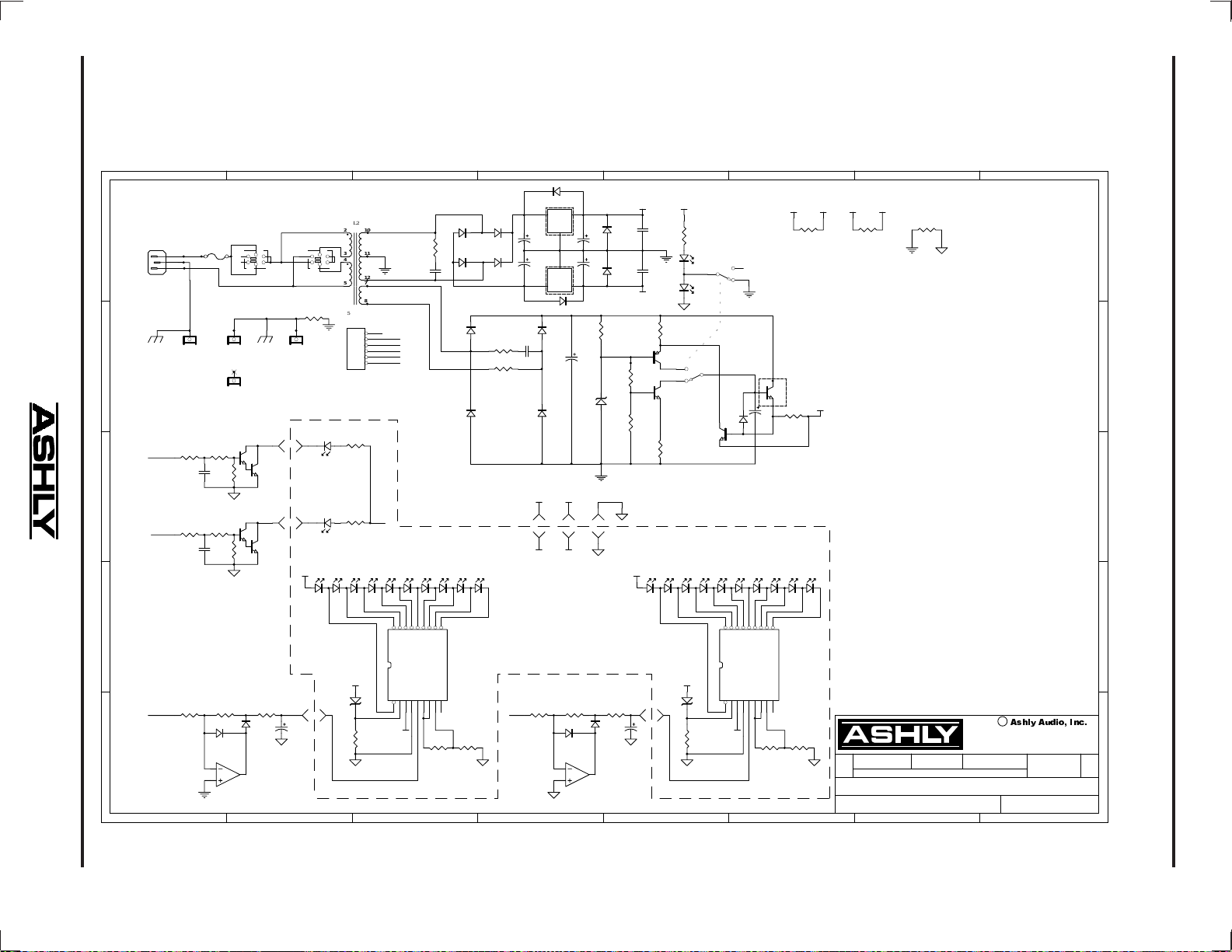
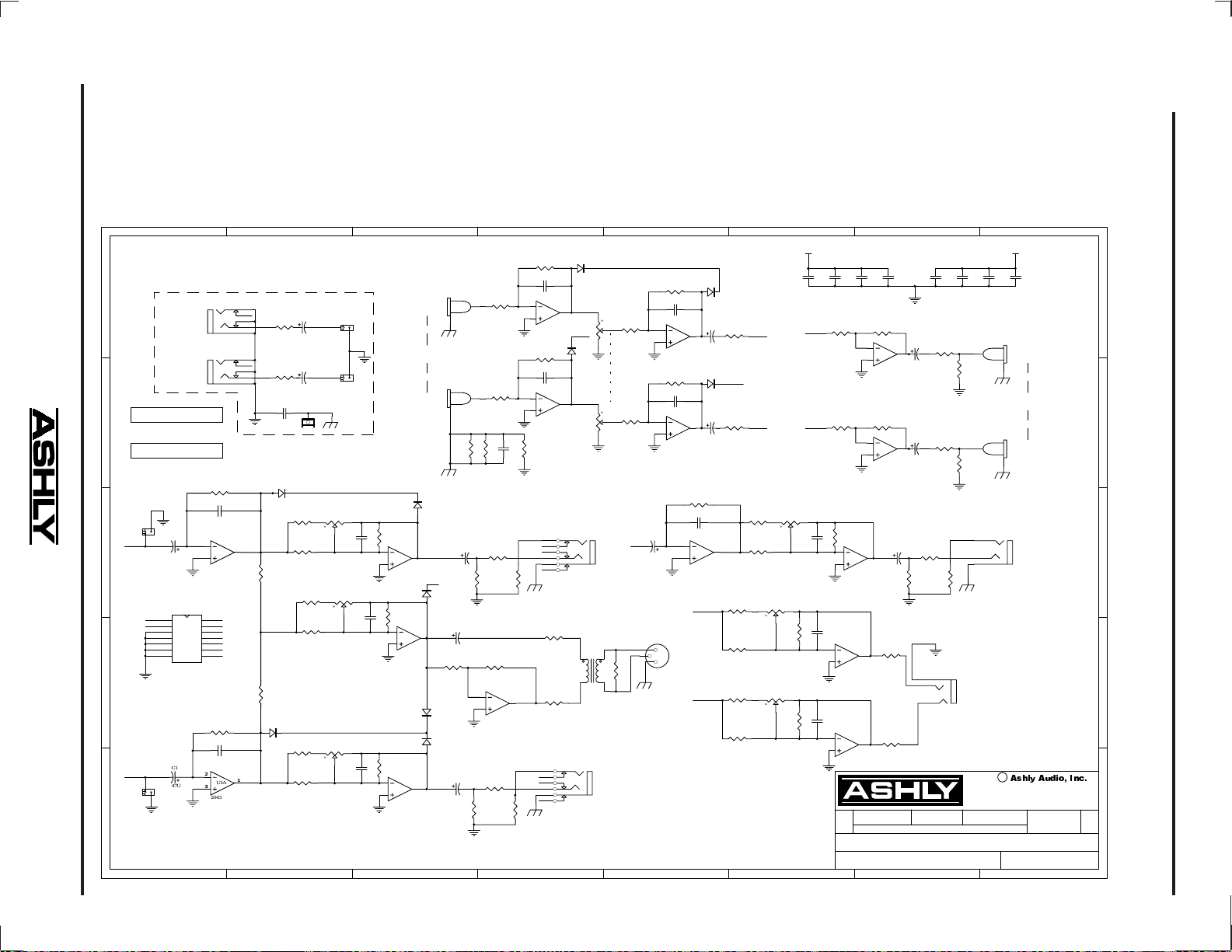
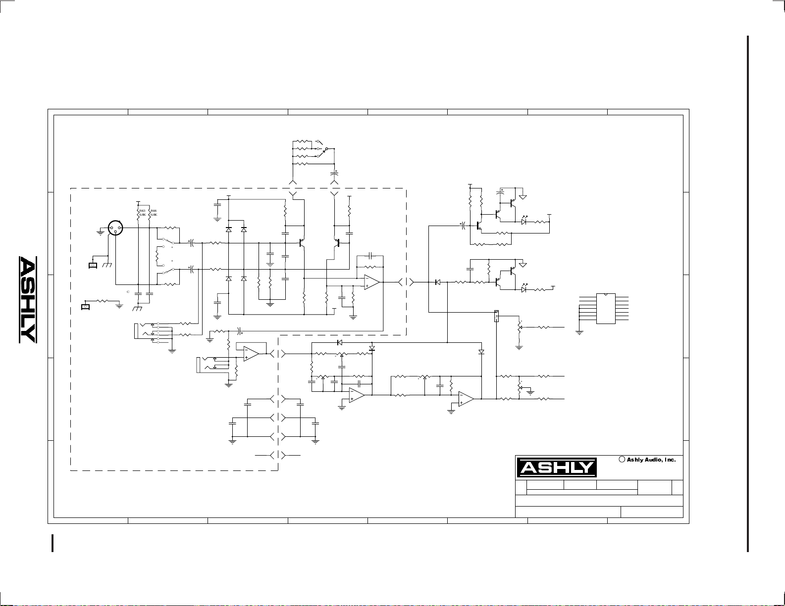
12 SCHEMATIC DIAGRAMS . . . . . . . . . . . . . . . . . . . . . . . . . . . . . . . . . . . . . . . . . . . 12-14
2
Page 3

Operating Manual - MX-406 Stereo Microphone/Line Mixer
The lightning flash with arrowhead
symbol, within an equilateral triangle, is
intended to alert the user to the presence
of uninsulated "dangerous voltage"
within the product's enclosure that may be
of sufficient magnitude to constitute a risk
of electric shock to persons.
TO REDUCE THE RISK OF ELECTRIC SHOCK, DO NOT R EMOVE COVER. NO USER SERVICEABLE PARTS INSIDE.
REFER SERVICING TO QUALIFIED SERVICE PERSONNEL.
TO REDUCE THE RISK OF FIRE OR ELECTRICAL SHOCK,
DO NOT EXPOSE THIS APPlIANCE TO RAIN OR MOISTURE.
TO REDUCE THE RISK OF FIRE, REPLACE ONLY WITH
SAME TYPE FUSE. REFER REPLACEMENT TO QUALIFIED
SERVICE PERSONNEL.
CAUTION
RISK OF ELECTRIC SHOCK
DO NOT OPEN
WARNING:
THIS APPARATUS MUST BE EARTHED
1. INTRODUCTION
Congratulations on your purchase of an Ashly
MX-406 stereo mic/line mixer , a professional, studio quality solution to everday mixing needs. MX-406 features
include six channels of mic or line inputs with mic input
pad, TRS insert points, and +48V phantom power. Each
channel has up to 60dB input gain, separate treble and
bass controls, an aux send control, level, and a stereo pan
control. An aux input is provided for a stereo program
source such as tape or CD. Outputs include aux master,
stereo line out (pre-master), stereo left and right, transformer balanced mono out, and stereo headphones. A
full 11 segment LED array indicates stereo output level.
Stereo main outputs use 1/4" jacks, stereo aux
input and line out use RCA connectors, and a transformer
isolated 600 ohm mono output uses an XLR connector.
Ashly mixers still use professional quality 16mm metal
shaft potentiometers for greater accuracy and long life
and of course, Ashly products come with a wor ry-free fiv e
year warranty.
The exclamation point within an eqilateral
triangle is intended to alert the user to the
presence of important operating and
maintenance instructions in the literature
accompanying the device.
transportation damage should the unit again require packing and shipping. In the event that damage has occurred,
immediately notify your dealer so that a written claim to
cover the damages can be initiated.
The right to any claim against a public carrier
can be forfeited if the carrier is not notified promptly and
if the shipping carton and packing materials are not available for inspection by the carrier. Save all packing materials until the claim has been settled.
3. AC POWER REQUIREMENTS
The MX-406 mixer will perform normally from
93 to 125 volts AC, 50-60Hz (some export models are
wired for 240 Volts and are labeled accordingly). Use
only properly grounded AC receptacles. To reduce the
risk of ground loop hum, use a central point for system
AC power distri bution. In the event of fuse failure , refer
this unit to a qualified service technician for fuse replacement using only the same type fuse. Power consumption
is less than 20 watts.
2. UNPACKING
As a part of our system of quality control, every
Ashly product is carefully inspected before leaving the
factory to ensure flawless appearance. After unpacking,
please inspect for any physical damage. Save the shipping carton and all packing materials , as they were carefully designed to reduce to minimum the possibility of
3
Page 4
Operating Manual -MX-406 Ster eo Microphone/Line Mixer
Treble
Bass
Level
Pan
Channel 1
-60
-40
-20
Input
(d B)
-12 +1 2
4
3
Aux
1
010
4
1
Clip
0
5
6
6
RL
Treble
Bass
7
9
7
8
Level
Channel 2
-60
-40
-20
Input
(d B)
-12 +1 2
3
Aux
1
Pan
1
Clip
0
5
6
4
010
6
4
RL
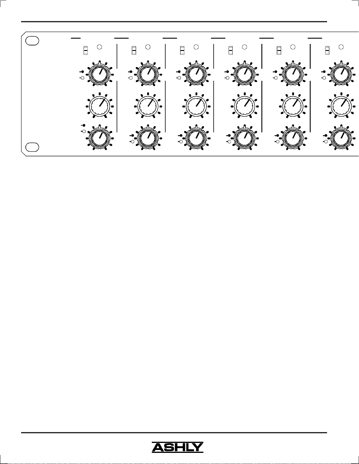
4. FRONT PANEL CONTROLS
4.1 Input Gain
This three position switch sets the operating level
of the microphone and line input preamp. The corresponding switch values -20db, -40dB, and -60dB refer not to
the actual gain, but rather to the expected nominal input
signal strength.
Treble
Bass
7
9
7
8
Input
(d B)
Level
Pan
-60
-40
-20
Aux
Channel 3
Clip
0
-12 +1 2
5
4
3
1
010
4
1
6
6
RL
Treble
Bass
7
9
7
8
Input
Level
Pan
-60
-40
-20
(d B)
Aux
Channel 4
Clip
0
-12 +1 2
5
6
4
3
1
010
6
4
1
RL
Treble
Bass
7
9
7
Level
8
Channel 5
-60
-40
-20
Input
(d B)
-12 +1 2
3
Aux
1
Pan
1
4
010
4
4.4 Aux
The aux send is an additional level control used to
send signal from each input channel to monitors, an effect
unit, or another mix.
six channel's aux level signals.
The aux master output combines all
The aux control is factory
set to pre-fader, pre-EQ, but can be interna lly switched to
post-fader, post EQ.
To make this change, refer the fol-
lowing procedure to a qualified service technician:
Channel 6
Clip
0
5
-60
-40
-20
Input
(d B)
Treble
Bass
6
7
9
6
7
8
RL
-12 +1 2
3
Aux
1
Level
Pan
1
Clip
0
5
6
4
7
8
010
4
9
6
7
8
RL
Best signal to noise ratio is obtained with higher
gain settings. It is therefore desirable to set the gain control as high as possible while still leaving 20dB of headroom for signal peaks. Line level inputs (1/4" jack) will
likely use a setting of -20dB, while mic inputs generally
require a setting of -40dB for close mic applications, and
-60dB for quieter signals. If a channel's clip LED is blinking, first turn down that channel's level control. If the
clip LED is still flashing, turn down the input gain.
4.2 Clip
Input Clip LEDs are peak sensitive and monitor
all critical points within the input channel. The clip LED
turns on whenever any portion of the audio path within
the input channel reaches a level 3 dB below actual clipping. Clipping in the MX-406 occurs at +20dB.
4.3 Treble/Bass
This concentric knob is used for broad EQ
changes to each input channel. Channel EQ consists of a
high shelf control (treble) at 4KHz, and a 250Hz low shelf
control (bass). EQ boost or cut is ±12dB.
Unplug the unit's AC power cord from the outlet.
Remove the bottom cover which is fastened by sev en 6-32
screws. Loca te the 3 pin header labeled AUX at the middle
of the back edge of the front portion of the channel circuit board. Remove the shunt bar from the "Pre" position
indicated on the circuit board legend and place the shunt
on the "Post" position.
4.5 Level and Pan
This concentric knob adjusts the level and stereo
position of each channel. If a channel's level control is
always turned up to 9 or more, try increasing the gain
first. Conv ersely , if the lev el control is consistently turned
down to 1 or less, decrease the gain setting first. Remember that the gain setting should be set as high as possible while still allowing 20dB of headroom.
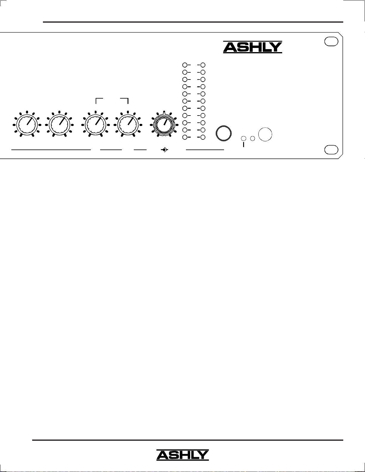
4.6 Stereo Line Input
This control adjusts the level of the RCA jack
stereo line input. It can be used for tape, CD, or DVD
audio inputs, and can also be used for a stereo effect return. For expanding the channel capacity of the MX-406,
4
Page 5
Operating Manual - MX-406 Stereo Microphone/Line Mixer
Stereo
Aux Input
5
6
4
3
2
1
010
Aux Master
Output
5
7
9
010
Stereo
Outputs
64
7
9
5
6
4
1
010
5
9
010
RightLeft
Mono/Phones
64
7
8
9
1
Mono
Output
4
0
5
10
6
7
9
Phon e s
the stereo line input can be used as stacking inputs for
supplementing the MX-406 with another mixer, such as
an Ashly LX-308 stereo line level mixer.
4.7 Aux Master Output
This control adjust the level of the aux master
¼" jack output, which gets it's signal from the six aux
level controls on the input channels. It is used for an
effects unit send, or can drive a power amplifier for monitors or an extra loudspeaker zone.
4.8 Stereo Output Level
These two controls determine the signal level to
the ¼" jack left and right outputs. They are used to drive
power amplifiers for the main loudspeakers, or to connect to a stereo recording device.
4.9 Mono Output Level
This control adjusts the level of the summed mono
output. It is completely independent of the main left and
right master controls. In other words, changes to either
left or right output level will not affect the mono output
level.
-L- -R-
Clip
+6
+3
0
-3
-6
-9
-12
-15
-18
-21
Output
VU
MX-4 0 6
Stereo
Six Channel
Mic/Line Mixer
Stereo
Headphones
Phantom
On
Power
4.11 Output Meters
A pair of peak reading 10 segment LED meters
are used to indicate stereo output level in VU. 0 VU is
equivalent to +4 dBu (1.228Vrms).
Green LED's are used below 0 VU, yellow above
0 VU and tw o red LED's indicate clipping. The c lip LED's
turn on 3dB below actual clipping, detecting excessive
signal level on any critical audio path within the master
section. If all outputs are turned down and there is still
clipping, then one or more inputs must be turned down.
4.12 Phantom Power LED
The phantom power switch is on the back panel.
When the switch is pressed in, the LED is lit and +48VDC
is applied to all six mic inputs for use with condenser
microphones. If there is a mix of both condenser and
dynamic microphones, the phantom power will not affect
the operation of the most dynamic mics.
4.10 Headphones Level
This control adjusts the level of the stereo signal
to the headphone jack. Headphones should have an impedance of 600 ohms or greater, or signal distortion may
result.
5
Page 6
Operating Manual -MX-406 Ster eo Microphone/Line Mixer
6
u
M
Model MX-406
Mad e In USA
Stereo
Outputs
+48V
CAUTION
RISK OF ELECTRI C SHOCK
DO NOT OPEN
100-120VAC
50-60Hz 15W
Phanto m
Power
Right
Left
Mono
Output
(Transformer
Bala n ced )
Aux
Master
Output
Stereo
Line Out
-L-
-R-
Stereo
Line
Input
Ch.
Tip=O
PUSH
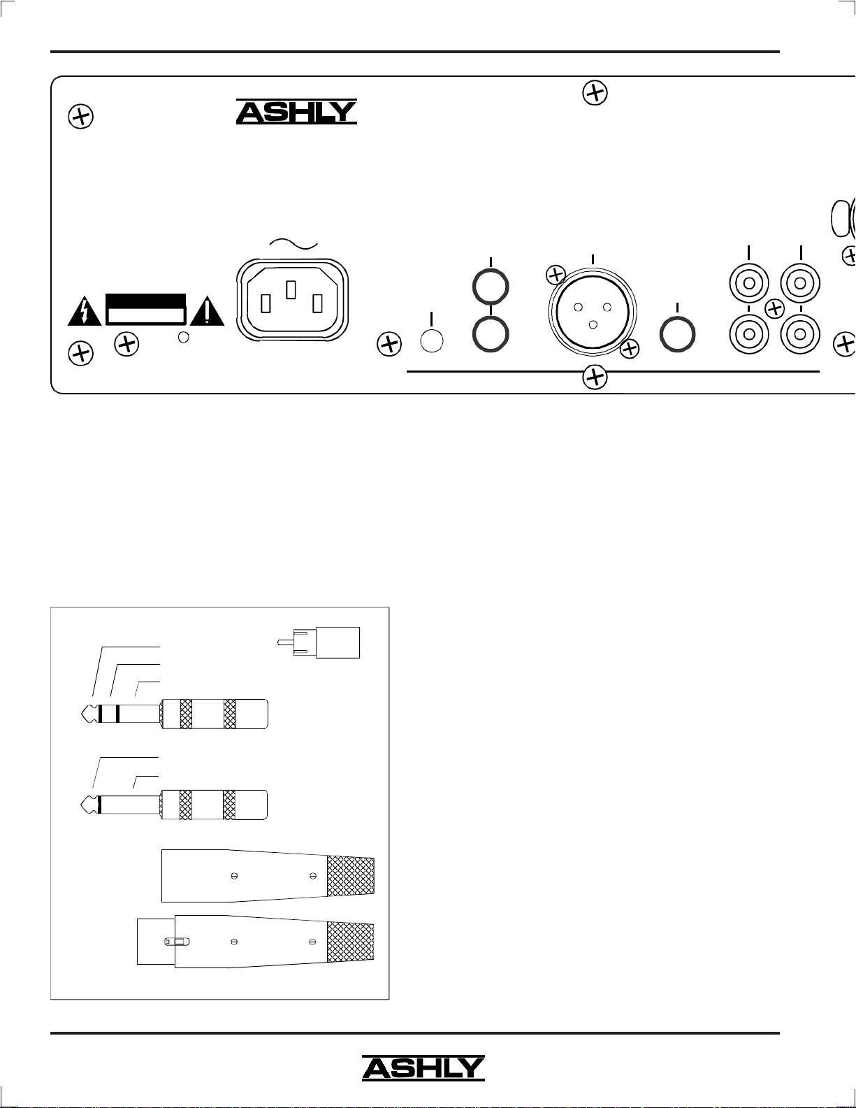
5. CONNECTORS AND CABLES
The MX-406 mixer is fitted with four types of
audio connectors: 3-pin XLR type male (mono output),
3-pin XLR type female (mic inputs), 1/4" tip-ring-sleeve
(TRS) phone jack, and RCA jack. Certain 1/4" jack connections may use an unbalanced mono plug, which is also
shown.
(Gnd)
Tip (+)
Ring (-)
Sleeve (Gnd)
Tip (+)
Sleeve (Gnd)
(+)
RCA Plug
Stereo Pho ne Plug
used for balanced
Mono Phone Plug
used for unbalanced
Two-conductor (twisted pair) shielded cable is
best for all XLR type connections. Belden No. 8412 or
its equivalent is an excellent cable due to its heavy construction. This type of cable should be used for all portable applications. Snake cables containing multiple
shielded pairs must be handled very carefully because the
leads tend to be fragile, and a broken conductor is difficult to repair.
If low level and high level lines are run parallel
for long distances, crosstalk may occur. In fact, the
crosstalk (signal leakage between cables) can cause an
electronic feedback loop, oscillation, and possibly damage to the equipment. To minimize crosstalk, physically
separate low level (microphone) cables from speaker
cables by the greatest feasible distance. At any point
where cables meet, run low level cables perpendicular to
high level or speaker cables. If low and high level or
speaker cables must be run parallel and in close proximity to one another, they should be bundled se parately. In
a permanent installation, av oid running speaker cables and
mic cable through the same conduit pipe.
6. REAR PANEL FEATURES
XLR p ins are
numbered
on the
connecto r
insert.
2 = (+)
3 = (-)
1 = (gnd)
6
Audio Connect or Types
XLR Male
XLR Fem ale
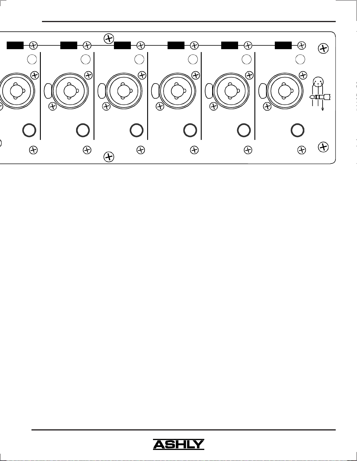
6.1 Microphone Input
The MX-406 microphone input is an active balanced type with a nominal impedance of 1200 ohms. Its
noise performance is best with a 200 ohm microphone.
The Mic input connector is a standard 3-pin XLR female
with the shield on pin 1, the (+) in-phase connection on
pin 2, and the (-) out-of-phase connection on pin 3.
Page 7
Operating Manual - MX-406 Stereo Microphone/Line Mixer
Ch.6
-20dB Pad
(Mic Only)
ic/Line Inpu t
Insert
ut R ing=In
Ch.5
-20dB Pad
(Mic Only)
Mic/Line Input
PUSH
Ch.5 Insert
Tip=Out Ring=In
Tip=Out Ring=In
Ch.4
-20dB Pad
(Mic Only)
Mic/Line Input
PUSH
Ch.4 Insert
Ch.3
-20dB Pad
(Mic Only)
Mic/Line Input
PUSH
Ch.3 Insert
Tip=Out Ring=In
6.2 Input Pad
The input pad is a 20dB attenuation switch on
the rear panel for use with the XLR microphone inputs.
It should normally be left in the "out" position for best
signal to noise ratio and should only be used when the
input is being overdriven with the gain control at its minimum setting.
Ch.2
-20dB Pad
(Mic Only)
Mic/Line Input
PUSH
Ch.2 Insert
Tip=Out Ring=In
Tip=Out Ring=In
Ch.1
-20dB Pad
(Mic Only)
Mic/Line Input
PUSH
Ch.1 Insert
3
2
1
(-)(+)
6.5 Stereo Line Input
The stereo line RCA inputs have a nominal operating level of -10dBu to match most consumer audio
sources. This signal is controlled by the Stereo Line Input dial on the front panel. This input is also used as a
stereo effects return, or as a stacking input for adding
additional mixers.
6.3 Line Input
The line input is a standard 1/4" TRS active balanced type found in the same "combo jack" connector as
the mic input. The line input balanced impedance is
20KΩ. It will accommodate a wide range of input levels.
6.4 Channel TRS Insert
A channel TRS insert patch point allows a device such as a remote level controller, graphic equalizer,
noise gate, compressor/limiter, or direct out recording
device to be used with one or more input channels.
The MX-406 TRS insert jacks use the tip for output and ring for the returning input. These signals will
be unbalanced, so cable length should be at a minimum
to maintain low noise.
To use the TRS insert as a Direct Line Output
(pre EQ) for recording, you must make a special cable
with tip and ring connected at the MX-406 end and a tipsleeve mono plug at the other end. Connecting tip and
ring at the mixer insert jack is necessary for uninterrupted
signal within the mixer when using direct line outputs.
6.6 Stereo Line Out
The stereo line outputs are nominal -10dBu "premaster", so they are not affected by the settings of the
main Left/Right output controls. These outputs would be
used for making a pre-output fader recording off of the
stereo mix, or for stacking the MX-406 stereo output into
another mixer.
6.7 Aux Master Output
The 1/4" jack aux master output is used to drive
a monitor or zone amplifier, effects processor, recording
device, or any function which requires level control independent from the main stereo mix. It is pseudo-balanced,
which means that while it is a single ended signal, it has
balanced impedance for low noise when driving an active
balanced input circuit over a long distance.
6.8 Mono Output
The XLR mono output combines the left and right
stereo signals (pre output fader), and uses an isolation
transformer capable of driving 600 ohm lines. Pin 1 is
7
Page 8
Operating Manual -MX-406 Ster eo Microphone/Line Mixer
ground, pin 2 is (+), and pin 3 is (-). This signal is determined by the mono output level control, with a nominal
operating level of +4dBu.
Note: The mono transformer-balanced output is designed to dri v e up to +24dBu into 600 ohm loads. Because
of the nature of an output transformer, the output level increases as the impedance of the terminating load becomes
higher than 600 ohms. Whereas a "direct-coupled" output stage like that of the right and left outputs will not change
as the load changes, any transformer used in an audio path is affected by its termination impedance. Since line level
inputs on audio devices are typically 10K
conventional active 10KΩ inputs with the transformer outputs.
6.9 Stereo Outputs
The 1/4" jack stereo right and left outputs are controlled by the left and right master. They are pseudobalanced TRS jacks with a nominal operating level of +4dBu into any load, and are capable of driving long lines.
6.10 +48V Phantom Power Switch
This switch applies +48VDC to all six XLR mic inputs to power condenser microphones. Phantom power will
not affect most dynamic mics, which may be used along with condenser mics.
Ω
or higher, expect a slight increase (2.5dB) in output level when driving
7. TYPICAL APPLICATIONS:
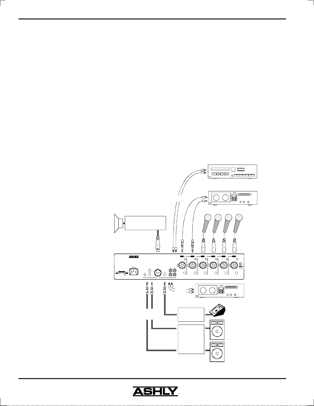
7.1 Small Sound Reinforcement System:
In the setup shown here, the MX-406
is used to mix typical sound sources
that might be found in a church, small
club, school theater or similar environment. Four of the input channels are
used for vocal microphones, while the
remaining two channels are used for
stereo accompaniment tracks. The stereo line input is used for additional
pre-recorded music such as that of a
movie soundtrack or CD player. Stereo line output RCA jacks are used to
record the event to a cassette, video
camera, or even a PC with recording
capabilities.
Stage monitors are fed using the aux
mix to the master aux output, and left
and right outputs drive the main speakers. The mono output drives a 70 Volt
distributed sound system amplifier,
used for plenum (ceiling) speaker installations.
70 Volt Distributed
Sound System Amp
(Mono
Output)
Mod el MX-406
Made I n USA
+48V
100-1 2 0V AC
50-60Hz 15W
Phant om
Power
CAUTION
RISK O F ELECTRIC SHOCK
DO NOT OPEN
(Stereo
Outputs)
VCR, CD, DVD Player
Audio Output
Accompaniment Tracks
Cassette Player
(Stereo
Line Input)
Four Vocal
Mic Inp ut s
Ch.6
Ch.5
Ch.4
Ch.3
Ch.2
-20dB Pad
-20dB Pad
-20dB Pad
(Mic Only)
(Mic Only)
Mic/Li ne Input
Mono
Output
Stereo
(Transf ormer
Stereo
Outputs
Right
Left
Bal a n c e d)
Line Out
Aux
-L-
Mast er
Output
-R-
(Aux)
Stereo
PUSH
Line
Input
Ch.6 Insert
Tip =O ut Ri ng=I n
(Stereo
Line Out)
Mic/Li ne Input
PUSH
Ch.5 Insert
Tip =O ut Ri n g=I n
Monitor
Mic/Li ne Input
PUSH
Ch.4 Insert
Tip =O ut Ri n g=I n
-20dB Pad
(Mic Only)
(Mic Only)
Mic/Li ne Input
PUSH
Ch.3 Insert
Tip =O ut Ri n g=I n
Mic/Li ne Input
PUSH
Ch.2 Insert
Tip =O ut Ri n g=I n
-20dB Pad
(Mic Only)
Ch.1
-20dB Pad
(Mic Only)
Mic/Li ne Input
231
PUSH
Ch.1 Insert
Tip =O ut Ri n g=I n
Monitor
MX-406
(-)(+)
Microphone
Mixer
Recording
Device
Amplifier
(R)
EQ,
Limiter,
Main
Right
Crossover,
Amplifier,
(L)
etc.
Main
Left
MX-406 Small Sound Reinfore c ement System
8
Page 9
Operating Manual - MX-406 Stereo Microphone/Line Mixer
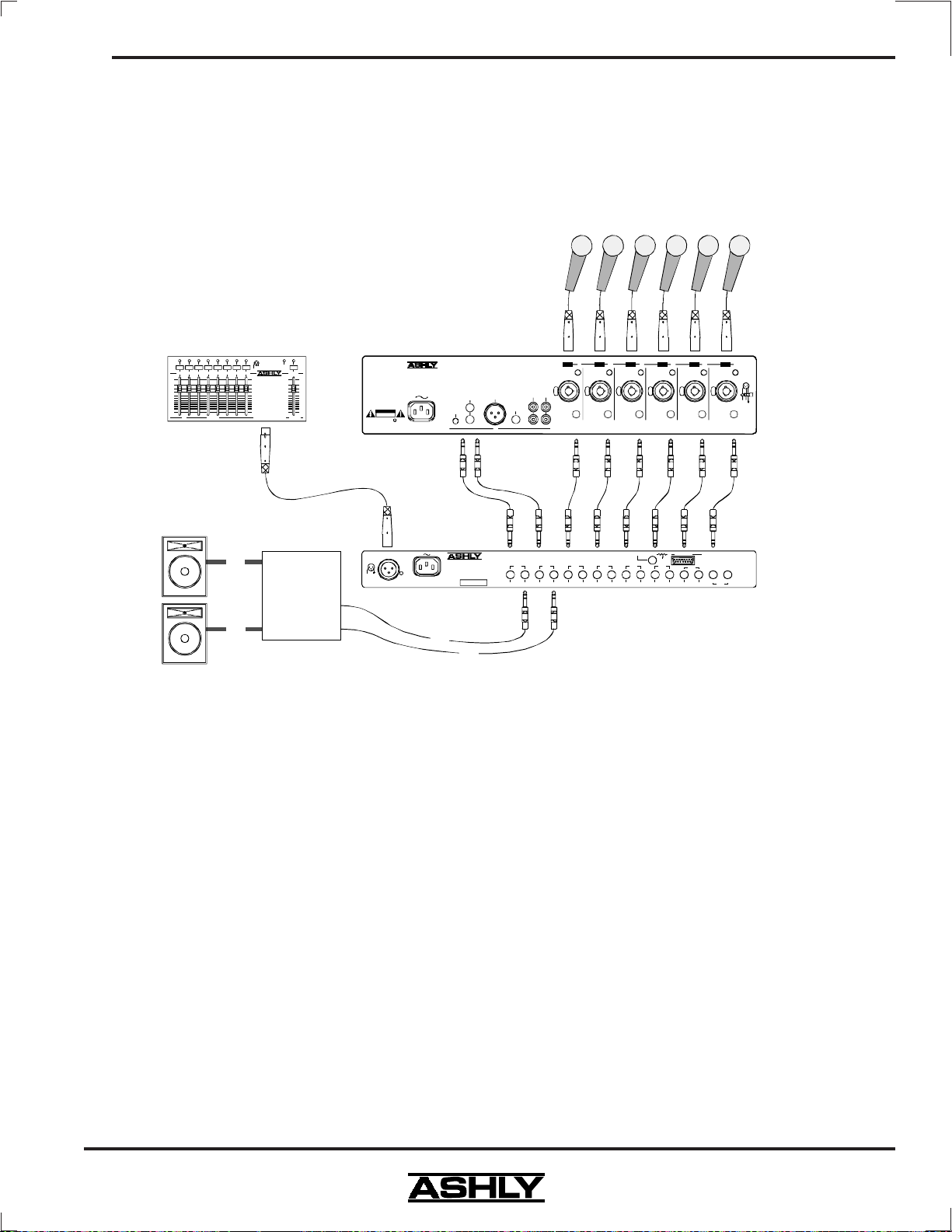
7.2 Meeting Room, Board Room, or Church Mixer Using Remote Control:
In this illustration, the MX-406 is interfaced with an Ashly VCM-88 eight channel remote level controller,
allowing the mixer to be operated from a distance by a non-technical person. Remote control of the VCM-88 is
achieved through the use of Ashly's RD-8 desk-top remote controller, RW-8 wall-plate version, or PC control using
Protea System Software. The RD-8 and RW-8 use a single mic ca ble for control data, while PC control uses RS-232
serial communications. Remote control can be located up to 1,300 feet from the main audio equipment rack.
Up To
Six Mic/Line
Inputs
RD-8 Re mote Con trol l e r
With 3-Pin XLR D ata C able
3
2
1
XLR Data Connector
On Top or Back.
Do Not Use
Transformers.
Data
Ch.1OnCh.2Ch.3 Ch.4 Ch.5 Ch.6 Ch.7 Ch.8 Master
+10
+5
0
-5
-10
-15
-20
-30
-50
-70
∞
-
V+
RD-8
Remo te Level Con trol
Gain (dB) Gain (dB)
Ch.6
Ch.5
Ch.4
Ch.3
Ch.2
Remote
Disabled
On
+10
+5
0
-5
-10
-15
-20
-30
-50
-70
-
∞
CAUTION
RISK O F ELECTRIC SHOCK
DO NOT OPEN
Model MX- 4 0 6
Made I n USA
100-120VAC
50-60Hz 15W
Mon o
Output
(Tra n sf o r m e r
Stereo
Bal an ce d)
Output s
+48V
Phant om
Power
Aux
Mast e r
Le ft
Output
Right
-20dB Pad
-20dB Pad
-20dB Pad
(Mic Only)
(Mic Only)
Mic/Li ne Input
Mic/Li ne Input
Stereo
PUSH
PUSH
Aux
Stereo
Input
Line Out
-L-
Ch.6 In ser t
Ch.5 Inse rt
Tip =O ut Ri n g=I n
Tip =O ut Ri n g=I n
-R-
(Mic Only)
Mic/Li ne Input
PUSH
Ch.4 Inser t
Tip =O ut Ri n g=I n
-20dB Pad
(Mic Only)
Mic/Li ne Input
PUSH
Ch.3 In ser t
Tip =O ut Ri ng=I n
-20dB Pad
(Mic Only)
Mic/Li ne Input
PUSH
Ch.2 In ser t
Tip =O ut Ri n g=I n
-20dB Pad
(Mic Only)
Mic/Li ne Input
PUSH
Ch.1 Inser t
Tip =O ut Ri n g=I n
Ch.1
231
(-)(+)
(L) (R)
MX-406
Microphone
Mixer
(Single Jack
TRS Inserts Use d)
Speaker
Zone 1
(L)
(R)
EQ,
Limiter,
Crossover,
Amplifier,
etc.
Remote Control
Data Input
231
V+
Data
100-120VAC
50-60Hz 15W
Ashly Audio Inc.
Model VCX-8 0
Made In USA
AVIS:
CHOC ELECTRIQUE.
NE PAS OUVRIR.
INPUTS are Active Balanced (Tip is +, Ring is -).
OUTPU TS May Be Wired Balanc ed or Unbal anced .
**TRS Insertion Is Available - See Owner's Manual**
RISQUE DE
Ch.8 Ch.7 Ch.6 Ch.5 Ch.4 Ch.3
** ** ** ** ** ** **
Master Outp ut
InIn Out I n Out In Out In Out Out In Out In Out
DC Control
1 - Ch.1
1210
CW
10K
Pin 1- 9
8 - Ch.8
2 - Ch.2
9 - Mas ter
1
3 - Ch.3
10 - Control CCW
4 - Ch.4
11 - (Aux Ground)
5 - Ch.5
12 - Control CW
9
6 - Ch.6
13-14 - (Aux Data In)
7 - Ch.7
15 - NC
Ch.2
**
In Out
Ch.1
(L)
(R)
VCM-88
Channels 1-6
Patc h ed Into
MX-406 Channel
Insert Points
Channels 7-8
Used For Mixer
Output Control
Speaker
Zone 2
Typical Application of MX-406 with VCM-88/RD-8 Remote Control
8. TROUBLESHOOTING TIPS
8.1 No Sound
Check the AC power. Is the power switch on? Check the level meters. If they are operating, the problem is
between the mixer and the later components in the system. If there is no meter activity, check to see that you really
have an input signal and that it is on the desired channel.
8.2 Distorted Sound
Something is being overdriven in the signal path. If the clip indicators are active, reduce the channel gain
and/or press in the pad switch on the rear panel. There are many gain adjustments in the mixer itself and probably
several others in other system components which makes it possible to ove rdrive an input section and then incorrectly
try to reduce the gain of the output section. The best way to approach setting gains is to establish the operating level
of input stages first by setting their gain as high as possible but leaving about 20dB of headroom for loud peaks, then
move on to set the master gain to produce a good meter reading. Proceed to set the gain of equalizers, limiters,
crossovers, and amplifiers following the mixer in the same manner, always working toward the later stages of the
system.
9
Page 10
Operating Manual -MX-406 Ster eo Microphone/Line Mixer
8.3 Excessive Noise
If the noise is in the form of hiss, the problem is
usually due to an input stage set for insufficient gain and
then compensating for it by increasing the level. Try increasing gain and reducing level. Also, check that the 20dB rear panel pad switch is not unnecessarily enabled.
8.4 Excessive hum
This is usually caused by "ground loops" in the
system wiring. A complex sound system with many
sources separated by significant distance and using several power outlets has many opportunities for this problem to occur. If possible, feed everything in the system
from one power source with a common ground. Use balanced input and output connections between widely separated components.
If you need help, get in touch with your Ashly
dealer or call an Ashly technical ser vice representative.
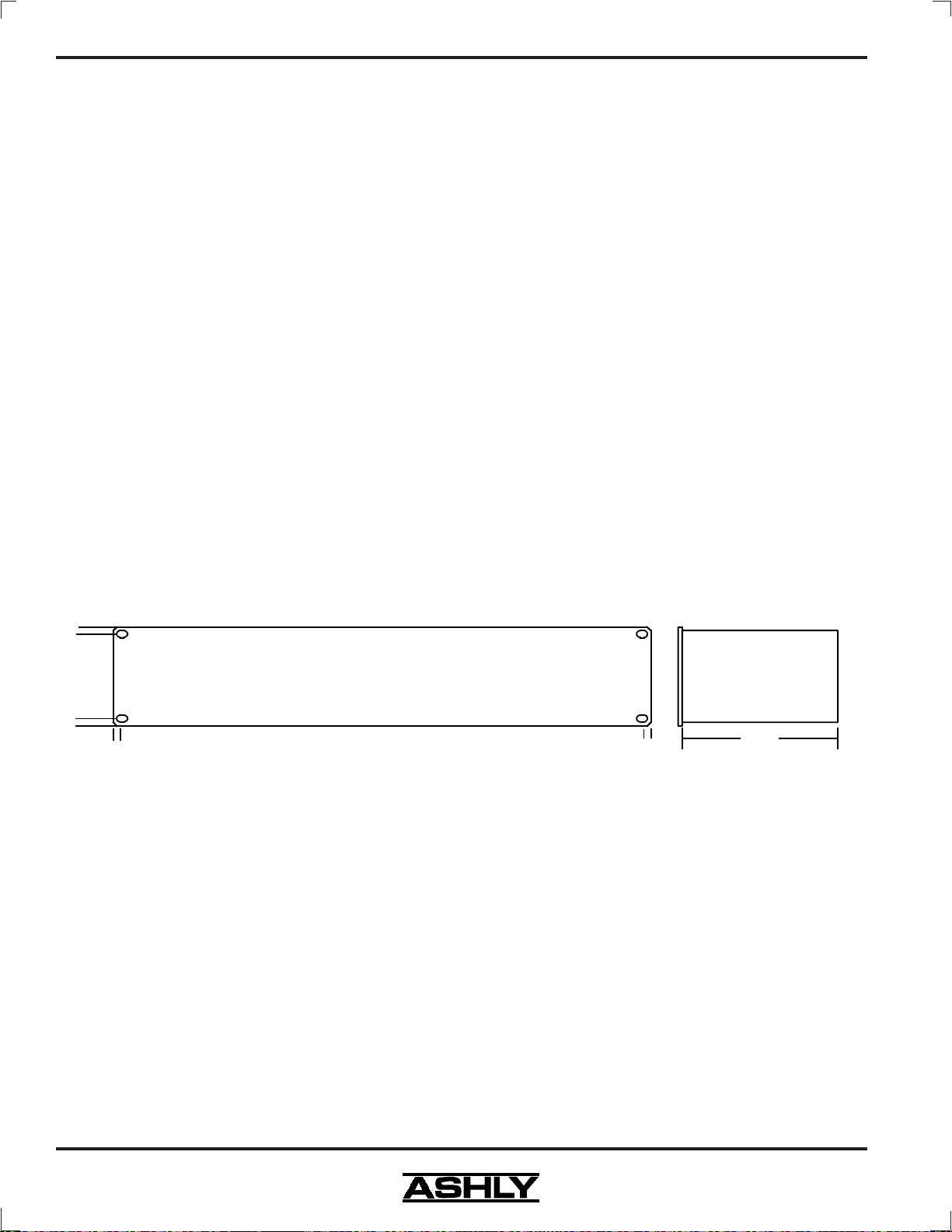
9. DIMENSIONS:
3.50
3.25
0.25
0.00
0.00
0.25
MX-406 Mixer
6.50
18.75
19.00
10
Page 11

Operating Manual - MX-406 Stereo Microphone/Line Mixer
10. SPECIFICATIONS
DISTORTION
THD at +4 dBu, 20Hz-20KHz . . . . . . . . . . . . . . . . . . <0.008%
THD at +12dBu, 30Hz-10KHz . . . . . . . . . . . . . . . . . . . <0.03%
IMD (SMPTE) at +12dBu . . . . . . . . . . . . . . . . . . . . . . . <0.03%
HUM & NOISE (20Hz-20KHz at max preamp gain)
equivalent input hum and noise . . . . . . . . . . . . . . . . .<-128dBu
residual output noise, TRS outputs,
all levels at minimum . . . . . . . . . . . . . . . . . . . . . . . . .<-110dBu
residual output noise, XLR output,
all levels at minimum . . . . . . . . . . . . . . . . . . . . . . . . . .<-98dBu
aux output, aux master and
all ch. aux at nominal . . . . . . . . . . . . . . . . . . . . . . . . . . <-90dBu
MAXIMUM VOLTAGE GAIN (±2dB)
MASTER
Mic/Line Input to Master Outputs . . . . . . . . . . . . . . . . . +92dB
Mic/Line Input to Mono Output, 600 ohm load . . . . . +88dB
AUX SENDS
Mic Input to Aux Master Output, pre ch. level . . . . . . . .72dB
Mic Input to Aux Master Output, post ch. level . . . . . . .92dB
Stereo Line In to Master Output . . . . . . . . . . . . . . . . . . . .28dB
FREQUENCY RESPONSE
20Hz-20KHz . . . . . . . . . . . . . . . . . . . . . . . . . . . . . . .+0.5/-1.0dB
11. WARRANTY INFORMATION
Thank you for your expression of confidence in
Ashly products. The unit you have just purchased is protected by a five-year warranty. To establish the warranty,
be sure to fill out and mail the warranty card attached to
your product. Fill out the information below for your
records.
Model Number ________________________________
Serial Number _________________________________
Dealer ______________________________________
Date of Purchase_______________________________
Dealer’s Address _______________________________
Dealer’s Phone ________________________________
Salesperson ___________________________________
EQUALIZATION
Bass . . . . . . . . . . . . . . . . . . . . . . ±12dB at 70Hz, shelving
Treble . . . . . . . . . . . . . . . . . . . . . . ±12dB at 8KHz, shelving
CROSSTALK
adjacent inputs, 20Hz-20KHz . . . . . . . . . . . . . . . . . . . .<-65dB
VU METERS
Stereo outputs . . . . . . . . . . . . . . . . . . . . . . . . . . . . .-21 to +6 VU
0VU = +4dBu
PEAK INDICATORS
Peak Clip indicator on each input channel and left and right
outputs, illuminates 3dB below clipping
PHANTOM POWER
+48 VDC applied to all Mic Inputs, switchable on rear panel.
Maximum total current draw = 80mA. Maximum single channel current draw = 14mA. Gradual power-up and down to eliminate "pops".
SHIPPING WEIGHT
13 lbs.
POWER REQUIREMENTS
120 VAC nominal, 93 VAC minimum, 50-60 Hz,
20 watts (240 VAC available)
*unless otherwise stated, specification conditions are:
150Ω source, Input Level set a t "-60", all other controls
set at nominal, XLR output into 600Ω or greater.
11
Page 12
12
y
C
Operating Manual -MX-406 Ster eo Microphone/Line Mixer
12. SCHEMATIC DIAGRAMS
11
7654321
R139
0
A->B @ 157%
Phone: Fax:
(716) 872-0010
Drawn B
James B Franks
D24
1N4003
HS1
1
3
In
Out
E
J3
L
G
N
ACINLET
AC-GND
D
R66
LCLIP
2.4K
C
R68
RCLIP
2.4K
B
R37
LPOST RPOST
33K
A
1 2 3 4 5 6 78
AC SWITCH
1/2 AGC
ACF
F1
AC
ACN
J4
J5
J7
Q5
2N4123
R109
390K
R112
C39
62K
.1U
Q7
2N4123
R110
390K
R113
C40
62K
.1U
R31
100K
D59
2
1
U8A
3
34184
120/240 SELECT
AC-SW
SW1
out
R138
EG
0
J6
J20B
J21B
Q6
2N4123
J20G
J21G
Q8
2N4123
+15M
J20A J20H
R55
1K
C31
D60
1.5U
L2
2 10
SW2
3 11
4
out
5127
51P7106
J26
None
D35
R101
2.7k
R
D36
R102
2.7k
R
24VAC1
24VAC2
35VAC1
35VAC2
8
6
35VAC1
5
35VAC2
4
24VAC1
3
GND
2
24VAC2
1
+15M
LEFT OUTPUT LEVEL (db)
G
18
-15M
D57
1N754
J21A J21H
LM3915
V+3V-2REF OUT
LED1
1
R91
+15M
4.7K
R100
1.5K
C36
.1U
65VA
10
LED911LED812LED713LED614LED515LED416LED317LED2
LED10
SIG IN5MODE
RLO4RHI6REF ADJ
9
8
7
R67
9.09k
D20
1N4003
D22
1N4003
D39YD41YD43GD45GD47GD49GD51GD53GD55
U10
LM3915
R115
33k
D28
1N4003
D29
1N4003
D37
Y
D21
1N4003
D23
1N4003
R99
1.5K
R61
10
.1U
U6
7815
C27
2
1000u
C28
HS2
1
1000u
U7
7915
2
3
In
Out
D25 1N4003
D30
1N4003
C35
J20C
J21C
D31
1N4003
+15M -15M
J20D
J21D
C33
100U
-15M+15M
Meter Card
R32
R38
100K
33K
D61
13
U8D
12
34184
C29
1.5u
C30
1.5u
J20E
J21E
+15
+15M
D27
C38
1N4003
D26
1N4003
R7
10K
R30
100K
D34
1N977
R80
3.3K
+15M
R56
1K
C32
D62
1.5U
14
R98
.1U
2.4k
GND
Power
Phantom
D32
SW3A
G
C37
.1U
-15
R105
18K
Q1
2N5401
6
4
Q2
2N5551
R24
220
Phantom
D33
SW3B
45P2600
3
2
1
45P2600
R
OUT
5
1N4148
D7
Q3
2N5551
RIGHT OUTPUT LEVEL (db)
G
18
1N754
D58
-15M
LM3915
LED1
1
R92
+15M
4.7K
V+3V-2REF OUT
HS3
23
Q4
1
TIP29C
C34
100U
10
LED911LED812LED713LED614LED515LED416LED317LED2
LED10
SIG IN5MODE
RLO4RHI6REF ADJ
9
8
7
R69
9.09k
R107
22
U11
LM3915
+15 +15M -15 -15M
R28
0
D38
D40YD42YD44GD46GD48GD50GD52GD54GD56
Y
R116
33k
R29
0
+48
Size
Sheet # of
B
S:\Engineering\CLIENT98\5400\10s5401b.sch
xxx PCB
APPROVED: Dwg #
8
C
$VKO\ $XGLR ,QF
847 Holt Road
Webster, NY 14580-9103
(716) 872-0739
10:56:30
Print Date
26-Jul-2002
E
D
C
B
Rev.
A
A
MX-406 Power and Metering
Page 13
13
y
-
N
E
D
C
B
A
7654321
D11
R12
10k
C21
J2D
D6
1N4148
Mono+
D1
1N4148
RPOST
LPOST
3
47P1304
1
J2C
2
47P1304
1
R1400R141
C4
47U
R4
10K
C6
47U
R6
10K
2
3
C2
47U
R2
10K
J13
-L
SUB I
MX406 Power and LEDs
10s5401b.sch
MX406 Input Channel
10s5402b.sch
J24
LBUS
-15M +48
+15M -15
RBUS
J25
J14
-R-
R3
10K
C15
27P
C3
6
U1B
47U
5
2043
J11
1 14
2 13
+15
3 12
AUX
4 11
GND-METER
5 10
RBUS
6 9
LBUS
7 8
DIP14
R1
10K
C14
C1
47U
1 2 3 4 5 6 78
27P
2
U1A
3
2043
R74
None
R75
None
C68
None
D4
1N4148
R45
2.7K
LPRE
7
R40
6.8K
R58
15K
+8dB Max, -4.2dB Mid
R57
15K
D2
1N4148
R46
2.7k
RPRE
1
R41
6.8k
J22
None
C12
LBUS
None
C13
RBUS
None
J23
None
BKT3
+12dB Max, +1.6dB Mid
R50
2k
R106
18K
LCLIP
VR1
B10K
LEFT MASTER LEVEL
VR3C
B10K
MONO MASTER LEVEL
VR2
B10K
RIGHT MASTER LEVEL
C18
27P
C20
27P
RCLIP
C19
27P
Left
STEREO AUX INPUT
Right
D3
1N4148
R34
33k
6
7
U2B
5
4560
LCLIP
R108
8.2k
6
7
U3B
5
4560
D5
1N4148
R35
33k
2
1
U2A
3
4560
27P
R13
13
10k
12
C22
27P
R15
9
10k
10
R142
C77
.001U
None
None
R20
100
R21
100
R5
10K
4560
Mono-
1
U3A
R19
100
R22
100
1N4148
34184
14
U4D
RCLIP
D8
1N4148
R14
10k
34184
8
U4C
+16.5dB Max, +5.6dB Mid
J9A
9
3
5
11
7
1
LEFT
OUTPUT
R59
10
2 7
3 6
R60
10
J9B
10
4
6
12
8
2
RIGHT
OUTPUT
L1
51P9010
T
LCLIP
D9
R73
22K
1N4148
R65
2.4K
R79
3.3K
R78
3.3K
C10
AUX
47U
MONO
OUTPUT
2
3
1
C17
27P
34184
9
U8C
10
R72
22K
34184
6
U8B
5
J8
R88
C9
47U
D10
1N4148
C8
47U
7
4.7K
RCLIP
R87
4.7K
AuxPre
R89 4.7K
R143 18K
LBUS
RBUS
R47
1.5K
R42
10K
+11.7dB Max, -1.5dB Mid
8
C16
27P
7
R16
10K
C23
27P
6
U9B
5
4560
LPRE
+20.2dB Max
R90 4.7K
RPRE
R14418K
VR5B
B20K
VR5A
B20K
B
+15 -15
C70
C71
C72
.1U
.1U
R10
10K
C7
34184
2
1
U4A
3
47U
R8
10K
C5
34184
6
7
U4B
5
47U
C11
AuxPost
1
U9A
4560
47U
R17
10K
R94
68
1
2043
R93
68
7
2043
Sheet # of
11
S:\Engineering\CLIENT98\5400\10s5400b.sch
A->B @ 157%
VR4
B10K
AUX MASTER LEVEL
VR3B
C100K
HEADPHONE LEVEL
VR3A
C100K
C69
.1U
.1U
R11
LPRE
10K
R9
RPRE
10K
R36
10k
C24
27P
2
3
R96
62K
C25
10pf
2
U5A
3
R97
C26
62K
10pf
6
U5B
5
Size
B
xxx PCB
APPROVED: Dwg #
C73
.1U
R49
2K
R48
2K
R25
100
R26
100
J1
47P3151
HEADPHONE
OUTPUT
C74
.1U
J2B
6
47P1304
R54
1K
STEREO LINE OUTPUT
J2A
5
47P1304
R53
1K
J10
47P3151
Phone: Fax:
(716) 872-0010
Drawn B
James B Franks
8
C75
C76
.1U
.1U
LEFT
4
RIGHT
4
AUX
OUTPUT
C
$VKO\ $XGLR ,QF
847 Holt Road
Webster, NY 14580-9103
(716) 872-0739
10:53:20
Print Date
26-Jul-2002
Rev.
E
Operating Manual - MX-406 Stereo Microphone/Line Mixer
D
C
B
A
A
MX-406 Motherboard Audio Sections
Page 14
14
y
T
Operating Manual -MX-406 Ster eo Microphone/Line Mixer
7654321
MIC GAIN
R121
560
SW6A
R131
2.55K
2.7k
R123
470
LOW
VR8A
EQ
C46
.1U
J18H
J17H
Q11
2N4125
B20k
C67
R132
2.55K
-15
HIGH
+20dB
+40dB
+60dB
D17
.22u
C50
3300U
VR8B
1N4148
B20k
C65
.033u
+15M
+15
R126
5.90K
C52
None
C56 100P
R127 5.90K
J17A
1
+20dB Max, +9.4dB Mid
2k
R70
R117
3.3k
J18A
Pre
VR7B
B20K
6
LEVEL
D19
1N4148
PEAKBUS
4
5
2
U12A
3
4560
R128
C57
5.90K
100P
D18
R124
1N4148
470
2.7k
R52
C58
100p
6
7
U13B
5
4560
R135
None
C64
None
R95
None
C43
.1U
R71
R111
2.4K
390K
R39
33k
C59
100p
2
U13A
3
4560
C63
None
R134
None
Q9
None
D16
1N4148
PostSig
1
PRE
J16
POST
R114
62K
Q14
None
R133
None
R136
None
Q12
2N4125
AUX SEND
R82
3.3K
VR7A
B5K
R83
3.3K
-.2dB Center
Q15
None
D64
None
SIGNAL
Q13
2N4125
D63
R
VR9
B10K
3
2
1
PAN
R104
None
CLIP
R103
2.7k
-15M
-15M
R86
AUX
3.3k
R85
LBUS
3.3K
R84
RBUS
3.3K
J12
-15M +48
1 14
+15M -15
2 13
3 12
4 11
5 10
6 9
7 8
DIP14
R125
5.90K
C51
None
R130
2.55K
J17B
J17D J18D
J17E J18E
J17F J18F
R122 560
R64 10
R81 3.3K
J18G
J17G
Q10
2N4125
C53
None
C54
100P
J18B
R51
C66
.22u
+15
C45
.1U
-15
E
+48
R43
R44
6.8K
21
C48
.001U
J19B
JACK-COMBO
6.8K
R119
620
Out
C60
SW5A
1
2
3
47U/63V
R118
160
-20dB PAD
C61
6
SW5B
5
4
47U/63V
Out
R120
620
C49
.001U
R77
22k
R76
22k
J15
INSERT
POINT
J19A
BKT1
BRKT-GND
BKT2
BRKT-GND
JACK-COMBO
3
G
R137
EG
None
LINE
INPUT
MIC INPU
D
C
B
+15
C41
.1U
D12
D13
1N4148
R62
10
R63
10
C42
.1U
R33
1N4148
C55
100P
D14
D15
R129
1N4148
1N4148
2.55K
C62
100k
47u
R27
100
6
7
U12B
5
4560
R18
10k
+15
C44
.1U
-15
C47
.1U
+15
AUX
GND-METER
RBUS
LBUS
8
E
D
C
B
J17C J18C
+48
Break-Away Back Panel PCB Front Panel Panel PCB
A
1 2 3 4 5 6 78
+48
Size
Sheet # of
11
B
S:\Engineering\CLIENT98\5400\10s5402b.sch
xxx PCB
APPROVED: Dwg #
A->B @ 157%
C
$VKO\ $XGLR ,QF
847 Holt Road
Webster, NY 14580-9103
Phone: Fax:
(716) 872-0010
Drawn B
James B Franks
(716) 872-0739
10:55:31
Print Date
26-Jul-2002
Rev.
A
A
MX-406 Input Channel
Page 15

Operating Manual - MX-406 Stereo Microphone/Line Mixer
15
Page 16

Operating Manual -MX-406 Ster eo Microphone/Line Mixer
ASHLY AUDIO INC. 847 Holt Road Webster, NY 14580-9103
Phone: (585) 872-0010 Fax: (585) 872-0739
Toll Free (800) 828-6308
www.ashly.com
2002 by Ashly Audio Corporation. All rights reser ved worldwide.
Printed in USA MX406 Rev 0 0802
 Loading...