

Page 1

Service manual: Washing machine
Type: WM70
Page 2

Service manual WM70
2
Page 3

Service manual
Type: WM70
Contents
Updates ...................................................................................................................................................................... 4
Introduction ............................................................................................................................................................. 5
Troubleshooting strategy .................................................................................................................................. 6
WM70.1 Overview Panel ............................................................................................................................7
Service menu ................................................................................................................................ 8
Fault indications ..........................................................................................................................10
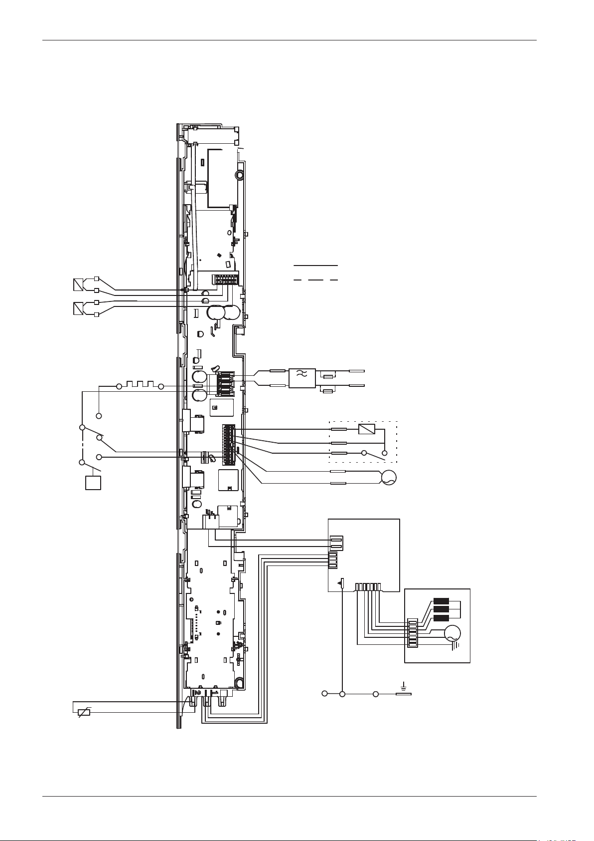
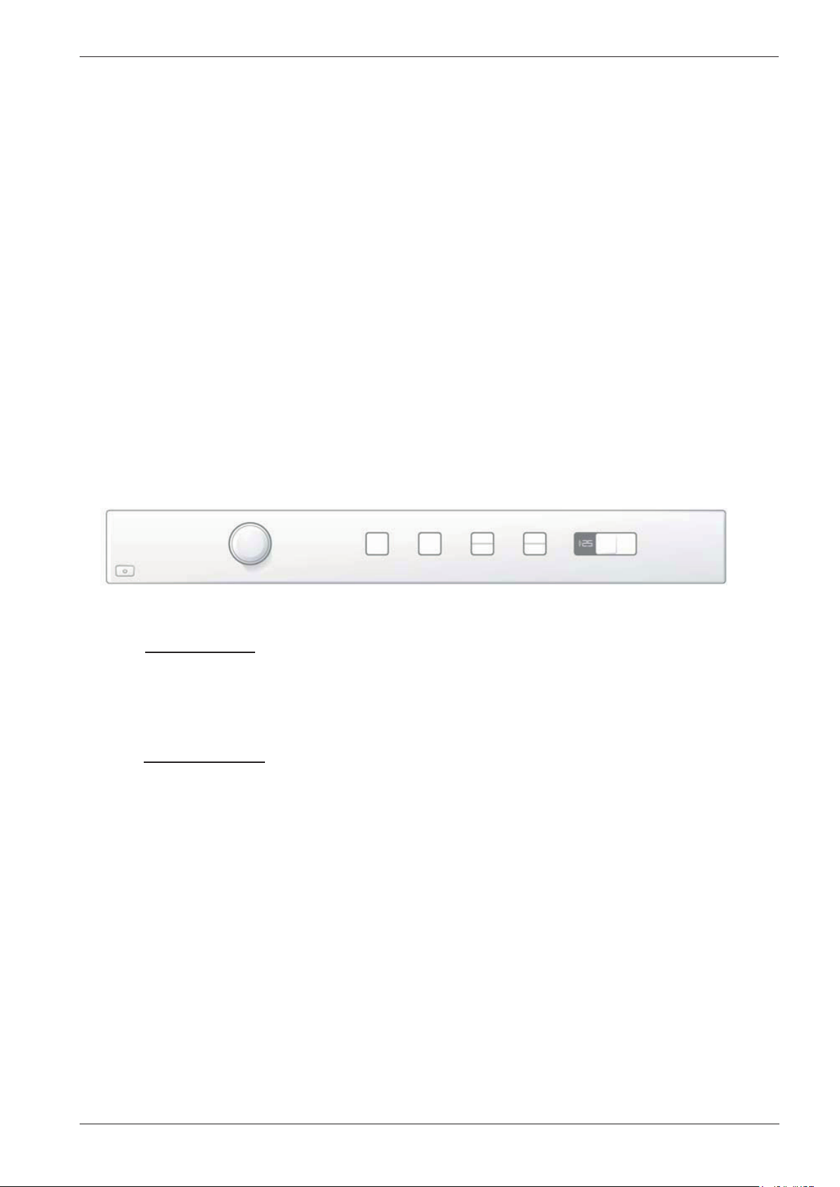
Wiring diagram WM70.1 CIM ...........................................................................................12
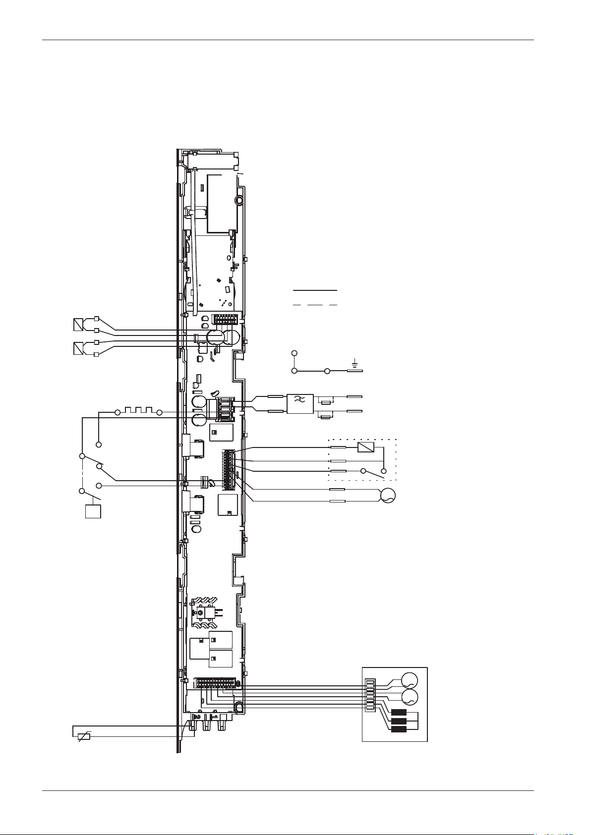
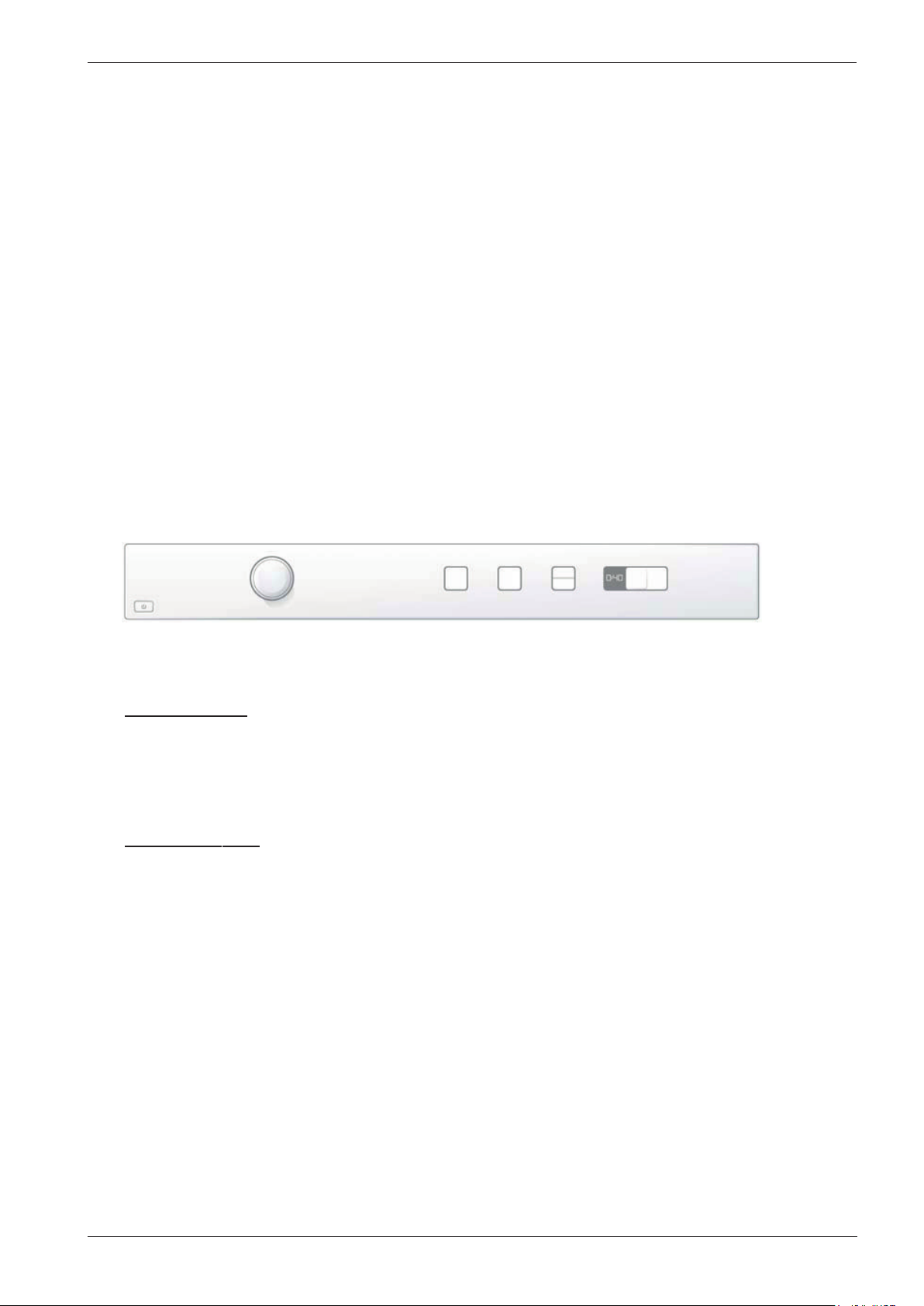
Wiring diagram WM70.1 UM ............................................................................................14
WM70.2 Overview Panel ..........................................................................................................................16
Service menu ...............................................................................................................................17
Fault indications ..........................................................................................................................18
Wiring diagram WM70.2 .....................................................................................................20
WM70.3 Overview Panel ..........................................................................................................................22
Service menu ...............................................................................................................................23
Shop program .............................................................................................................................28
Fault indications ..........................................................................................................................29
Wiring diagram WM70.3 ......................................................................................................32
Components and measurement values WM70 ................................................................................34
Thermistor measurement values WM70 ..............................................................................................35
Technical data WM70 .......................................................................................................................................35
Tools ...........................................................................................................................................................................36
Rehanging the door ...........................................................................................................................................37
Replacing panels, control unit and detergent compartment .....................................................40
Replacing front panel, door, cover plate and the hinges ...............................................................43
Emergency opener for door lock ..............................................................................................................44
Wash agitator removal ....................................................................................................................................45
Page 4
Service manual WM70
Updates
Rev Date Description Sign
01 2010-10-06 First version developed BPA
02 2010-10-12 Service menu WM70.1, WM70.2, WM70.3 updated ISC
03 2012-04-20 Replacing front panel, door, cover plate and the hinges updated EH
4
Page 5
Service manual WM70
Introduction
You are holding the service manual for WM70 type washing machines.
It should be easy to service a washing machine. It is important that you, as a service technician, are
given the conditions to be able to carry out work in an efficient and satisfactory way. Our hope is
that this service manual is a useful tool for your daily work.
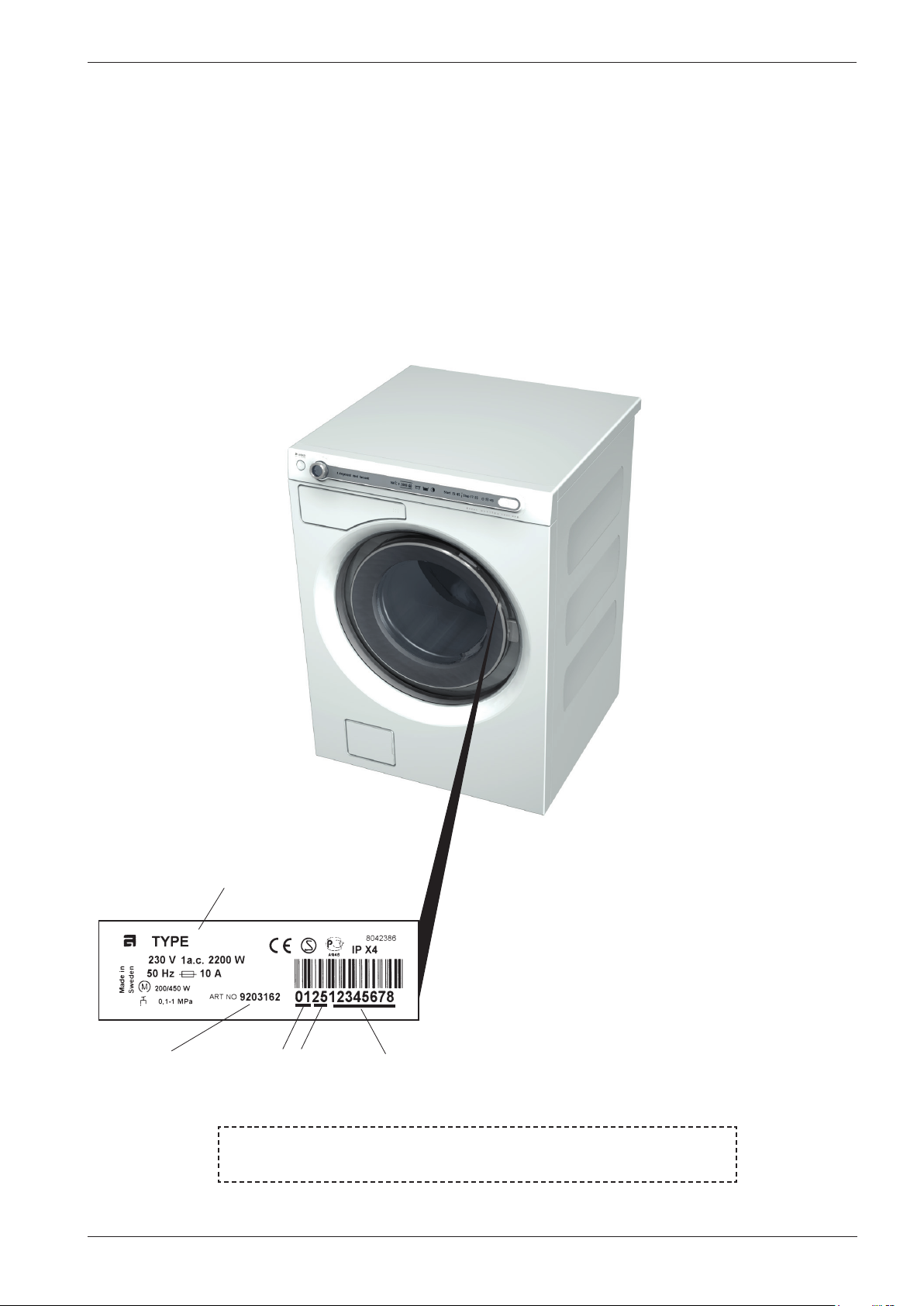
The type designation is located by the inside of the glass door (see image below).
Asko Appliances AB
SE-534 82 Vara
Sweden
Type designation
WM70
WM 60.C
Year
Product number Serial number
Week
OPERATING INSTRUCTIONS
Always have the operating instructions for the machine available during service
5
Page 6
Service manual WM70
Troubleshooting strategy
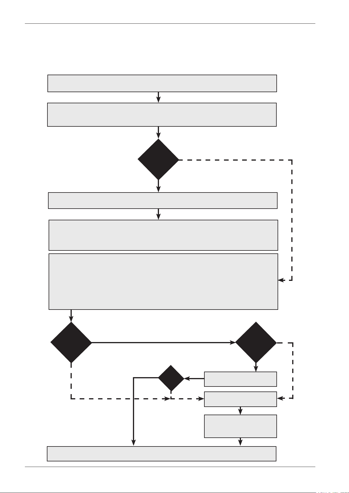
Troubleshooting is an important part of the service callout, and as such we have drawn up a
troubleshooting strategy that describes, in broad terms and step by step, what you need to do to find
and diagnose faults arising in our machines.
• Ask the customer to describe the problem.
• Check whether the customer’s description matches the reported fault.
• Check that the machine is correctly installed:
- Electrical connection - Drainage
- Water connection - Machine correctly levelled
Fault
found?
Incorrect installation or external factors that affect performance and functionality (for
example, water pressure, electrical supply, drainage).
The machine operates normally. No deviations can be found. The customer probably
needs to be informed about proper use of the machine. If necessary, also inform the
customer about the guarantee conditions and the fact that the customer will be charged
for the callout.
Open the service menu:
1. Check the settings
2. Run a test cycle
3. Note any fault codes
If the above actions do not uncover the fault:
• Conduct general troubleshooting. Use the documentation available at ServiceSaver
(service manuals, service memos, wiring diagrams and other documents).
No
Yes
Fault
found?
No
Yes
Yes
OK?
No
Fault
diagnosed?
Yes
Repair and check
function/safety.
Contact technical support
for assistance.
Carry out the actions
suggested by technical
support.
No
Satisfied customer!
6
Page 7
Service manual WM70
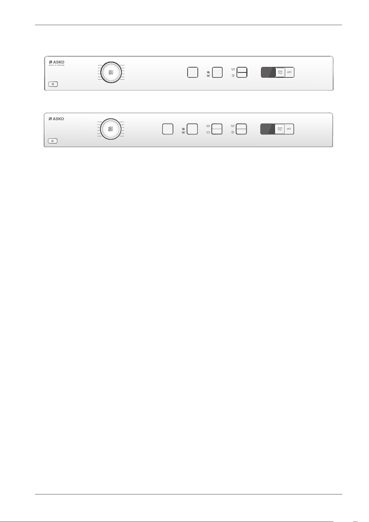
Overview: Panel WM70.1
Programs: 10
Options: 4 or 6
Settings: 1
95°
40°
60°
30°
50°
20°
95°
40°
60°
30°
50°
20°
1600
400
1200
800
1400
400
1000
800
7
Page 8
Service manual WM70
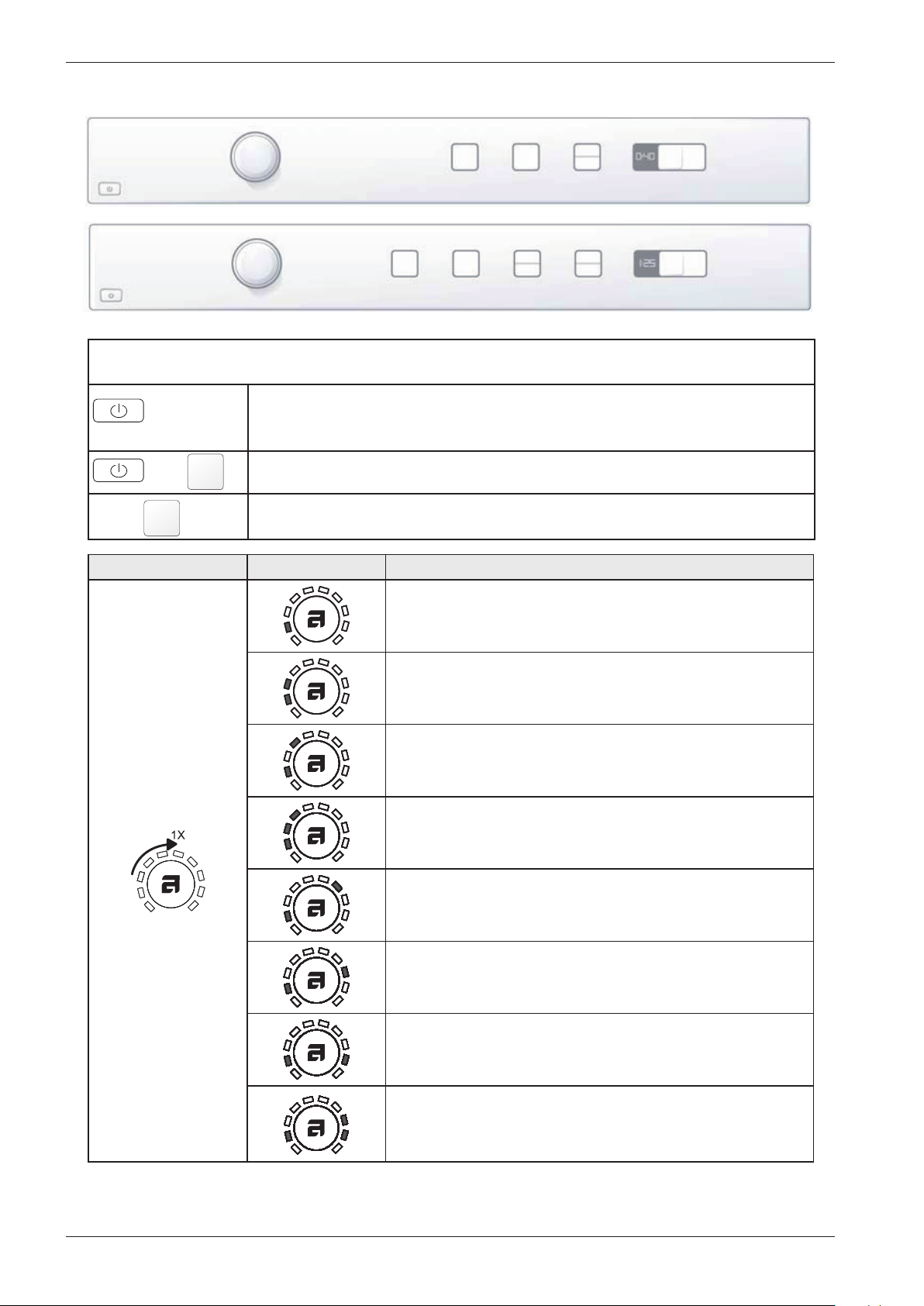
Service menu WM70.1
S3 S4 S7
S1
S2 S3 S4
S1
How to get to the service menu
+
Turn/press SCREENING Comments/Instructions
Is the machine turned on: turn off the power first at the main switch.
Press and hold the button for super wash (S4) while you press the main switch.
Press button (S4) three times within 5 seconds. You are about to component
testing.
No component
S6
S9
S7
S9 S10 S11
S10 S11
Intake valve 1 starting
Intake valve 2 starting
Intake valve 1 and 2 starting
Heater starts and warms up to a maximum of 60 ° C
Drain pump starts
Spin and drain pump starts
Door opening
8
Page 9
Service manual WM70
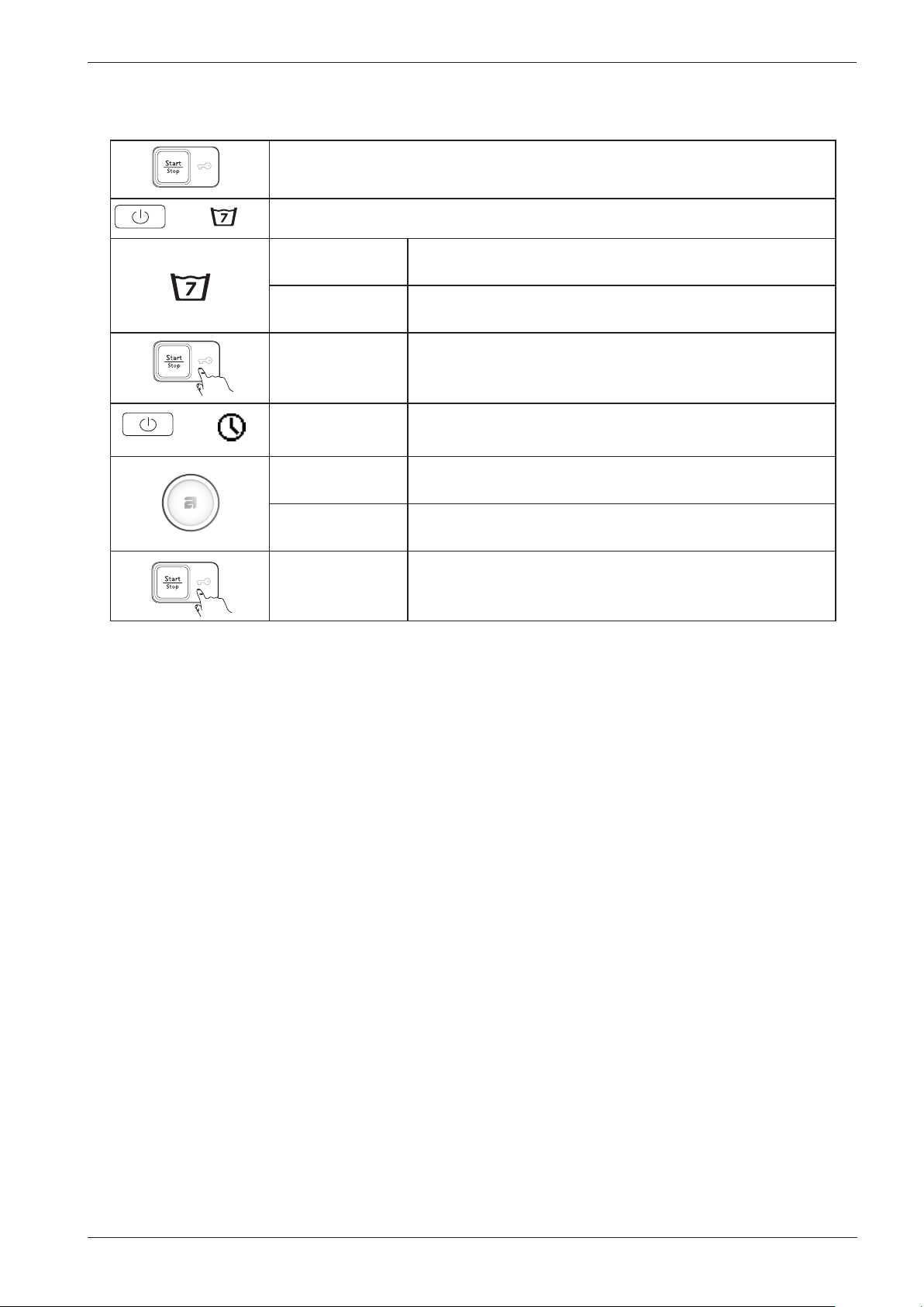
Service menu WM70.1 cont.
Press the Start/Stop button to exit the service menu
+
+
”Auto door on/off”
Ad O
Ad F
r F
r 0
”Auto door on”
”Auto door off”
Press button (S11) to store your selection
”Extra rinses Off/On”
”Extra rinses off ” - 3 rinses
”Extra rinses On” 5 rinses
Press button (S11) to store your selection
9
Page 10
Service manual WM70
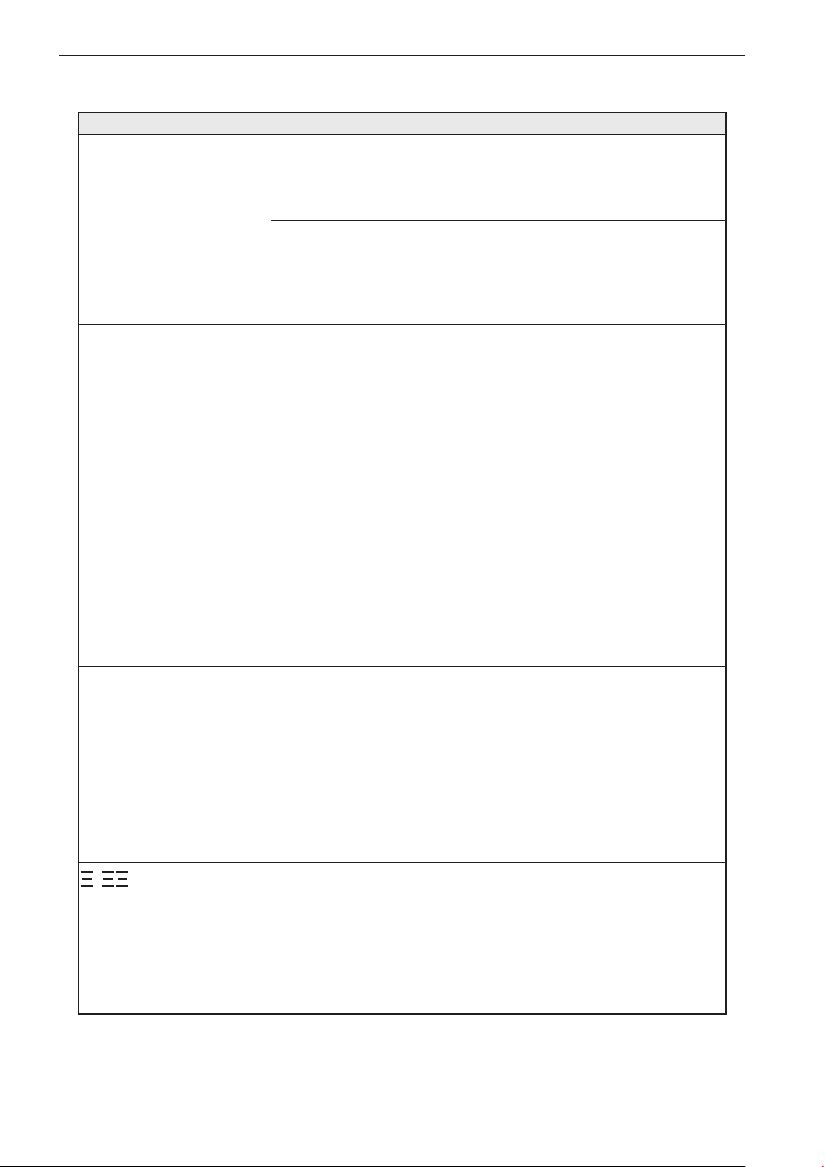
Fault indications WM70.1
Error messages on the display Cause Action
F10 – Overflow Too much water in the
machine.
The drainage pump is
running but the machine
is empty.
F11 - Water outlet fault The drainage pump
has been running for 3
minutes. Water remains
in the machine.
The wash cycle has been
interrupted and the
programme reset.
Service action:
- Check the machine's level system, inlet valve
and drainage pump.
- Check for any leaks.
Service action:
- The overflow cut-out at the bottom of the
machine has been activated (some models
only).
- Check for leaks.
Information to customer:
- Check that no objects are stuck in the
drainage hose outlet.
- Check that the drainage pump is not
blocked by foreign objects.
- Check that there are no kinks in the
drainage hose.
Service action:
- If the pump only runs for a short while
(approximately 20 seconds), this indicates
a fault in the level system. Check the level
sensor and hoses.
- Check wiring and voltage to the pump. If
necessary, replace the pump and/or control
unit. After implementing corrective action,
run the Drain programme or press the
Key (door opening) button to empty the
machine.
F12 – Water inlet fault If the correct water level
is not achieved within 5
minutes the wash cycle
will be interrupted.
- Unbalance detection After 10 failed attempets
to spin the load the
machine has stoped to
spin beacuse of to high
umbalance.
Information to customer:
- Check that the tap on the water pipe is open.
Service action:
- Check that the filter in the machine's water
intake is not blocked.
- Check the inlet valve. If necessary, replace
the valve.
- Check voltage to the inlet valve. If there is
no voltage, this could be due to a fault in
the level system, wiring or control unit.
Information to customer:
- Small loads with heavy items can cause this
problem when these articles are difficult to
redistribute.
10
Page 11
Service manual WM70
PERSONAL NOTES
11
Page 12
Service manual WM70
CIRCUIT DIAGRAM WM70.1 CIM
80 886 20 - 01
RESISTANCES AT ROOM TEMPERATURE (CA. 20°C/68°F)
VALUES WITHIN +/-10% ARE REGARDED AS NORMAL COMPONENT
F: RADIO INTERFERENCE SUPPRESSION FILTER 680K Ohm
EL: HEATING ELEMENT 25 Ohm
AP: DRAIN PUMP 50 Hz 144 Ohm
AP: DRAIN PUMP 60 Hz 76 Ohm
LL: DOOR LOCK, 1-2 122 Ohm
NTC: THERMISTOR 6.1 - 3.8 K Ohm
IV 1: INLET VALVE 1 3.7 K Ohm
IV 2: INLET VALVE 2 3.7 K Ohm
MO: MOTOR, 1-3 4,3±7% Ohm
1-2 4,3±7% Ohm
2-3 4,3±7% Ohm
MCU: MOTOR CONTROL UNIT
N: PRESSURE SWITCH
TS: PRESSURE SENSOR
TG: TACHO GENERATOR
BA: CONTAINER
INKB: INCOMING GROUND
WIRES IN ALL MACHINES
INTERNAL CONNECTION
*A FUSE CONNECTION USA & CANADA
EL
IV2
IV1
<N
N14
N12
N16
N11
NTC
EL
F
INKB
BA
AP
LL
L
N
3
1
2
*A
*A
TOTAL RESET
TURN OFF POWER (S1)
WAIT FOR AT LEAST 5 SEC
HOLD DOOR OPENING (S11)
TURN ON POWER (S1)
CABLE POSITIONS
1: MOTOR COMMUNICATION
2: THERMISTOR
3: INLET VALVES
4: DOOR LOCK, DRAIN PUMP, PREASSURE SWITCH
8: POWER
9: HEATING ELEMENT, PREASSURE SWITCH
10:
MOTOR POWER
MCU
MO
TG
S1
SERVICE MENU
TURN OFF POWER (S1)
WAIT FOR AT LEAST 5 SEC
HOLD START/STOP (S10)
TURN ON POWER (S1)
PRESS START/STOP (S10) 5 TIMES TO ENTER SERVICE MENU
PRESS DOOR OPENING (S11) TO CHANGE MENU STEP
ROTATE DIAL TO CHANGE IN STEP
PRESSING START/STOP (S10) STORES AND EXITS SERVICE MENU
Wiring diagram WM70.1 CIM
12
Page 13
Service manual WM70
This document must not be copied without
our written pemission, and the contents
thereof must not be imparted to a third party
nor be used for any unauthorized purpose.
Contravention will be prosecuted.
Asko Appliances AB
CIRCUIT DIAGRAM WM70.1 CIM
80 886 20 - 01
RESISTANCES AT ROOM TEMPERATURE (CA. 20°C/68°F)
VALUES WITHIN +/-10% ARE REGARDED AS NORMAL COMPONENT
F: RADIO INTERFERENCE SUPPRESSION FILTER 680K Ohm
EL: HEATING ELEMENT 25 Ohm
AP: DRAIN PUMP 50 Hz 144 Ohm
AP: DRAIN PUMP 60 Hz 76 Ohm
LL: DOOR LOCK, 1-2 122 Ohm
NTC: THERMISTOR 6.1 - 3.8 K Ohm
IV 1: INLET VALVE 1 3.7 K Ohm
IV 2: INLET VALVE 2 3.7 K Ohm
MO: MOTOR, 1-3 4,3±7% Ohm
1-2 4,3±7% Ohm
2-3 4,3±7% Ohm
MCU: MOTOR CONTROL UNIT
N: PRESSURE SWITCH
TS: PRESSURE SENSOR
TG: TACHO GENERATOR
BA: CONTAINER
INKB: INCOMING GROUND
2010-10-19
TOTAL RESET
TURN OFF POWER (S1)
WAIT FOR AT LEAST 5 SEC
HOLD DOOR OPENING (S11)
TURN ON POWER (S1)
S1
S11S10
S4S2 S3
S6
S7
S9
SERVICE MENU
TURN OFF POWER (S1)
WAIT FOR AT LEAST 5 SEC
HOLD START/STOP (S10)
TURN ON POWER (S1)
PRESS START/STOP (S10) 5 TIMES TO ENTER SERVICE MENU
PRESS DOOR OPENING (S11) TO CHANGE MENU STEP
ROTATE DIAL TO CHANGE IN STEP
PRESSING START/STOP (S10) STORES AND EXITS SERVICE MENU
Wiring diagram WM70.1 CIM
13
Page 14
Service manual WM70
CIRCUIT DIAGRAM WM70.1
80 886 21-02
RESISTANCES AT ROOM TEMPERATURE (CA. 20°C/68°F)
VALUES WITHIN +/-10% ARE REGARDED AS NORMAL COMPONENT
F: RADIO INTERFERENCE SUPPRESSION FILTER 680K Ohm
EL: HEATING ELEMENT 25 Ohm
AP: DRAIN PUMP 50 Hz 144 Ohm
AP: DRAIN PUMP 60 Hz 76 Ohm
LL: DOOR LOCK, 1-2 122 Ohm
NTC: THERMISTOR 6.1 - 3.8 K Ohm
IV 1: INLET VALVE 1 3.7 K Ohm
IV 2: INLET VALVE 2 3.7 K Ohm
MO: MOTOR, 1-3 3,7±7% Ohm
1-2 3,6±7% Ohm
2-3 3,6±7% Ohm
MCU: MOTOR CONTROL UNIT
N: PRESSURE SWITCH
TS: PRESSURE SENSOR
TG: TACHO GENERATOR
BA: CONTAINER
INKB: INCOMING GROUND
TOTAL RESET
TURN OFF POWER (S1)
WAIT FOR AT LEAST 5 SEC
HOLD DOOR OPENING (S11)
TURN ON POWER (S1)
S1
2010-10-27
SERVICE MENU
TURN OFF POWER (S1)
WAIT FOR AT LEAST 5 SEC
HOLD START/STOP (S10)
TURN ON POWER (S1)
PRESS START/STOP (S10) 5 TIMES TO ENTER SERVICE MENU
PRESS DOOR OPENING (S11) TO CHANGE MENU STEP
ROTATE DIAL TO CHANGE IN STEP
PRESSING START/STOP (S10) STORES AND EXITS SERVICE MENU
Wiring diagram WM70.1 UM
IV2
IV1
EL
N14
N11
N12
CABLE POSITIONS
2: THERMISTOR
3: INLET VALVES
4: DOOR LOCK, DRAIN PUMP, PREASSURE SWITCH
8: POWER
9: HEATING ELEMENT, PREASSURE SWITCH
MOTOR COMMUNICATION, MOTOR POWER
10:
*A FUSE CONNECTION USA & CANADA
WIRES IN ALL MACHINES
INTERNAL CONNECTION
EL
INKB
BA
N
F
*A
L
*A
3
2
1
LL
NTC
<N
N16
MO
AP
TG
RO
3
2
1
14
Page 15
Service manual WM70
Wiring diagram WM70.1 UM
RESISTANCES AT ROOM TEMPERATURE (CA. 20°C/68°F)
VALUES WITHIN +/-10% ARE REGARDED AS NORMAL COMPONENT
F: RADIO INTERFERENCE SUPPRESSION FILTER 680K Ohm
EL: HEATING ELEMENT 25 Ohm
AP: DRAIN PUMP 50 Hz 144 Ohm
AP: DRAIN PUMP 60 Hz 76 Ohm
LL: DOOR LOCK, 1-2 122 Ohm
NTC: THERMISTOR 6.1 - 3.8 K Ohm
IV 1: INLET VALVE 1 3.7 K Ohm
IV 2: INLET VALVE 2 3.7 K Ohm
MO: MOTOR, 1-3 3,7±7% Ohm
1-2 3,6±7% Ohm
2-3 3,6±7% Ohm
MCU: MOTOR CONTROL UNIT
N: PRESSURE SWITCH
TS: PRESSURE SENSOR
TG: TACHO GENERATOR
BA: CONTAINER
INKB: INCOMING GROUND
S3
S1
S4
S7
S9
S10
S11
TOTAL RESET
TURN OFF POWER (S1)
WAIT FOR AT LEAST 5 SEC
HOLD DOOR OPENING (S11)
TURN ON POWER (S1)
SERVICE MENU
TURN OFF POWER (S1)
WAIT FOR AT LEAST 5 SEC
HOLD START/STOP (S10)
TURN ON POWER (S1)
PRESS START/STOP (S10) 5 TIMES TO ENTER SERVICE MENU
PRESS DOOR OPENING (S11) TO CHANGE MENU STEP
ROTATE DIAL TO CHANGE IN STEP
PRESSING START/STOP (S10) STORES AND EXITS SERVICE MENU
2010-10-27
CIRCUIT DIAGRAM WM70.1
80 886 21-02
This document must not be copied without
our written pemission, and the contents
thereof must not be imparted to a third party
nor be used for any unauthorized purpose.
Contravention will be prosecuted.
Asko Appliances AB
15
Page 16
Service manual WM70
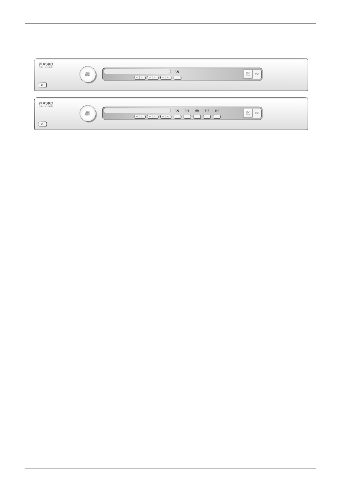
Overview: Panel WM70.2
Programs: 12
Options: 1 or 5
Settings: 3
16
Page 17
Service manual WM70
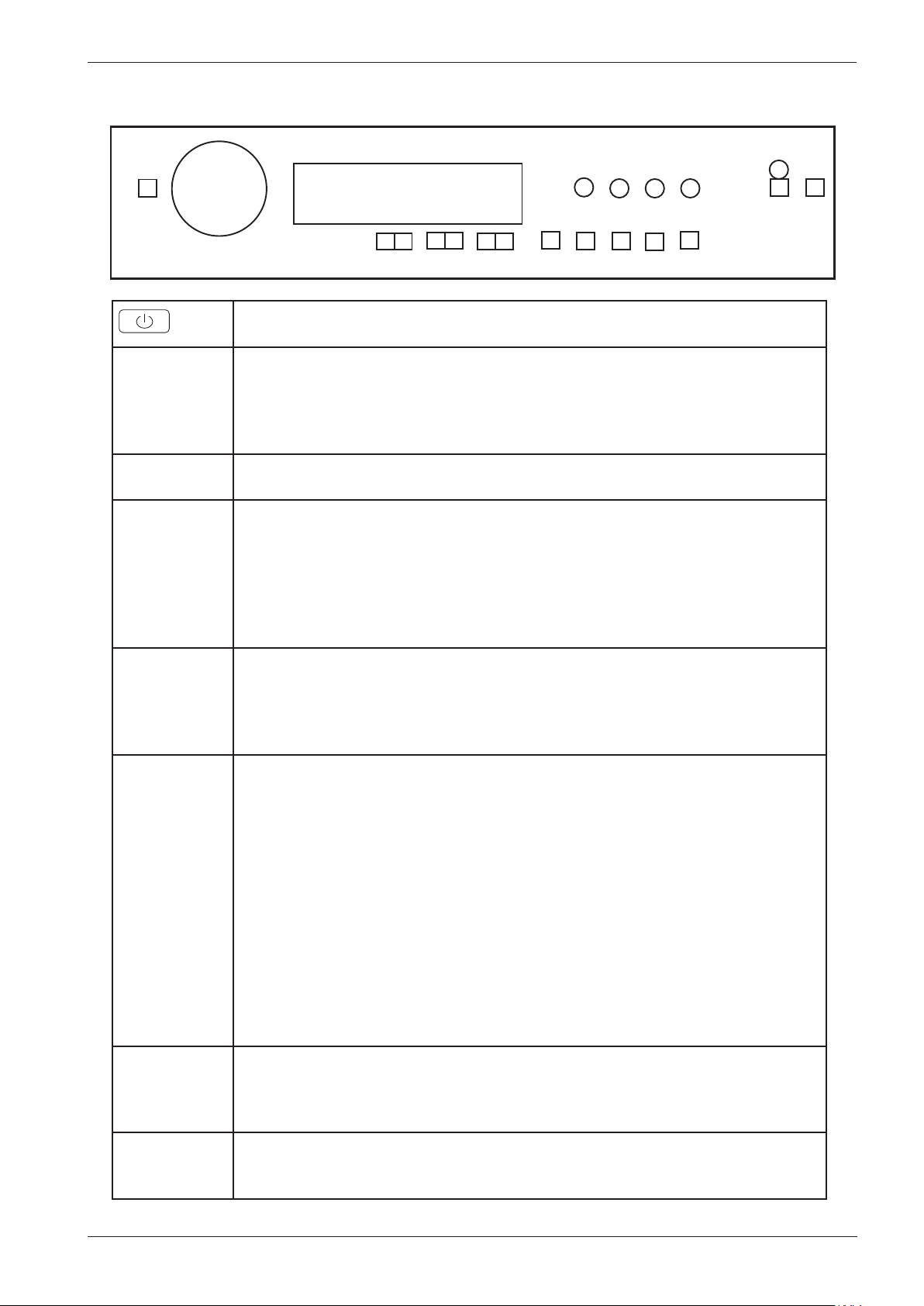
Service menu WM70.2
J1
S1
LCD
L1L5L2
L3
L4
L6
S13
S14
S6
NOTE!
Turn
J1
S4 S5
Switch off, and then on main power.
•Wait for at least 5 seconds
•Press down button S6
•Turn on the power
•Pressing S6 when power on followed by 3 pushes on S6 within 5 sec enters the
service menu.
Make all selections. Pressing S13 stores all selections made in service menu and leaves
service mode.
Tracking data reed out
SP: (software programming date: year week
CM: (control unit manufacturing date: year week
SV1: (Software version)
SV2: (Software version)
NC: Number of cycles
Press S14 next step is accessed.
Failure reed out
Rotating J1 will display 2nd and 3rd last deviating fault, ex “Thermistor fault (2); 30” ,
“Over flow (3); 20”
Failure record is cleared by total reset
Pressing S14 next step is accessed.
Diagnostics
Separate test of auxiliary components.
Rotating J1 each component will be turned on (with a 1 sec delay) and inputs
detected in sequence:
“Testing” (no component),
“Testing valve 1” (inlet valve 1 on),
“Testing valve 2” (inlet valve 2 on),
“Testing valve SM” (inlet valve 1 and 2 on),
“Testing heater” (heater on until max 60°C),
“Testing motor” (normal action),
“Testing drain” (drain pump on),
“Testing spin” (spin sequence, drain pump on),
“Testing door”.
Pressing S14 components will be off and next step is accessed.
Spin speed
Turn J1 counter clockwise 1500 rpm, 1600 rpm, 1700 rpm, 1800 rpm, default or
clockwise 1800 rpm, 1700 rpm ...
Pressing S14 next step is accessed or S13 to store or leave service mode.
Reset
By pressing S13, the machine returns to the default settings.
S6 S7
S8S2 S3
S10
S11
S12S9
17
Page 18
Service manual WM70
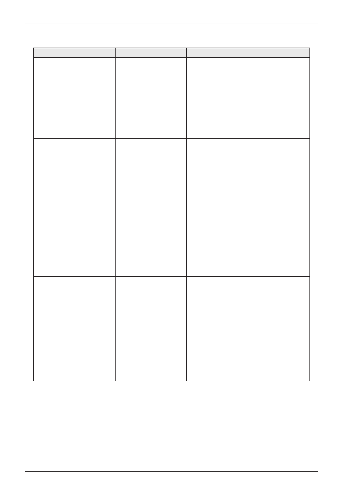
Fault indications WM70.2
Error messages Cause Action
Over flow fault Too much water in the
machine.
The drain pump is on,
without any water in the
machine.
Water outlet fault 1. The drain pump has
been activated more
than 3 minutes. There is
still water in the machine.
2. The wash cycle is
interrupted and the
program is cleared.
Service action:
Check the machine’s level system, inlet valve
and drain pump. Make sure that there is no
leaks.
Service action:
The overflow protection at the bottom of
the machine is activated (not all models).
Make sure that there is no leaks (water on
the machines base)
Customer information:
1. Check that no objects are stuck in the
drainage hose outlet.
2. Check that the drain pump is not blocked
by foreign objects.
3. Check that there are no kinks in the
drainage hose.
Service action:
1. If the pump only runs for a short while
(approximately 20 seconds), this indicates
a fault in the level system. Check the level
sensor and hoses.
2. Check wiring and voltage to the pump. If
necessary, replace the pump and/or control
3. After implementing corrective action, run
the Drain program or press the Key button
(door open) to empty the machine.
Water inlet fault If the correct water level
is not reached within 5
minutes, the wash cycle
is interrupted.
Security fault The door is open. Close the door
Customer information:
1. Check that the tap on the water pipe is
open.
Service action:
1. Check that the lter in the machine’s water
intake is not blocked.
2. Check the inlet valve. If necessary, replace
the valve.
3. Check voltage to the inlet valve. If there is
no voltage, this could be due to a fault in the
level system, wiring or control unit.
18
Page 19
Service manual WM70
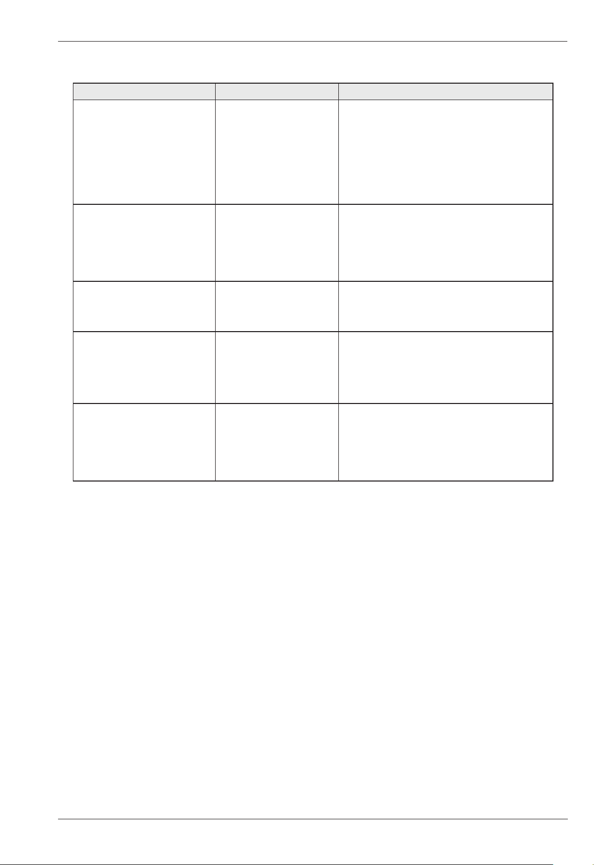
Fault indications WM70.2 cont.
Error messages Cause Action
1. The circuit for the
Thermistor fault
Temperature fault The temperature is
Engine fault No signal from Tacho or
Pressour sensor fault Iindicated if the level
thermistor is open.
2. The thermistor is
faulty.
3. The measurment value
for the thermistor is
<300 Ω (>120 °C).
raised < 5 °C/41°F within
10 minutes. The wash
cycle continues to next
step
MCU.
drops to 0 within 30
seconds of the first
rinsing.
Service action:
Check the thermistors function. If needed,
replace it.
Service action:
Check the heater, cables, thermistor and level
system.
Service action:
Check the output from the MCU and the
wiring between the motor and the MCU
Service action:
Check the leakage
Unbalance detection After 10 failed attempets
to spin the load the
machine has stoped to
spin beacuse of to high
umbalance.
Information to customer:
- Small loads with heavy items can cause this
problem when these articles are difficult to
redistribute.
After carrying out corrective actions as above, reset the fault indications by pressing the DOOR
OPERING BUTTON at the same time as the main power switch.
19
Page 20
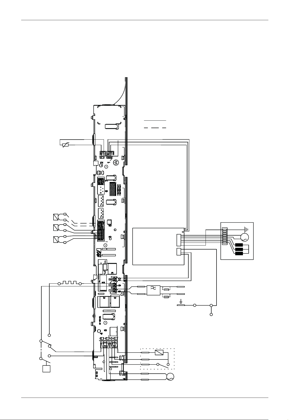
Service manual WM70
WIRES IN ALL MACHINES
INTERNAL CONNECTION
RESISTANCES AT ROOM TEMPERATURE (CA. 20°C/68°F)
VALUES WITHIN +/-10% ARE REGARDED AS NORMAL COMPONENT
F: RADIO INTERFERENCE SUPPRESSION FILTER 680K Ohm
EL: HEATING ELEMENT 25 Ohm
AP: DRAIN PUMP 50 Hz 144 Ohm
AP: DRAIN PUMP 60 Hz 76 Ohm
LL: DOOR LOCK, 1-2 122 Ohm
NTC: THERMISTOR 6.1 - 3.8 K Ohm
IV 1: INLET VALVE 1 3.7 K Ohm
IV 2: INLET VALVE 2 3.7 K Ohm
IV 3: INLET VALVE 3 3.5 K
MO: MOTOR, 1-3 4,3±7% Ohm
1-2 4,3±7% Ohm
2-3 4,3±7% Ohm
MCU: MOTOR CONTROL UNIT
N: PRESSURE SWITCH
TS: PRESSURE SENSOR
TG: TACHO GENERATOR
BA: CONTAINER
INKB: INCOMING GROUND
EL
IV2
IV1
<N
N14
N12
N16
N11
NTC
EL
F
INKB
BA
TS
AP
LL
MO
MCU
3
2
1
CABLE POSITIONS
1: MOTOR COMMUNICATION
2: THERMISTOR
3: INLET VALVES
4: DOOR LOCK, DRAIN PUMP, PREASSURE SWITCH
8: POWER
9: HEATING ELEMENT, PREASSURE SWITCH
10: MOTOR POWER
L
N
3
1
2
TG
S1
TOTAL RESET
TURN OFF POWER (S1)
WAIT FOR AT LEAST 5 SEC
HOLD DOOR OPENING (S14)
TURN ON POWER (S1)
SERVICE MENU
TURN OFF POWER (S1)
WAIT FOR AT LEAST 5 SEC
HOLD S6 OR S7
TURN ON POWER (S1)
PRESS S6 OR S7 3 TIMES TO ENTER SERVICE MENU
PRESS DOOR OPENING (S14) TO CHANGE MENU STEP
ROTATE DIAL TO CHANGE IN STEP
PRESSING START/STOP (S13) STORES AND EXITS SERVICE MENU
STEP 1: PRODUCT DATA
STEP 2: FAILURE DATA
STEP 3: COMPONENT TEST
*A FUSE CONNECTION USA & CANADA
*A
*A
IV3
Wiring diagram WM70.2
20
Page 21
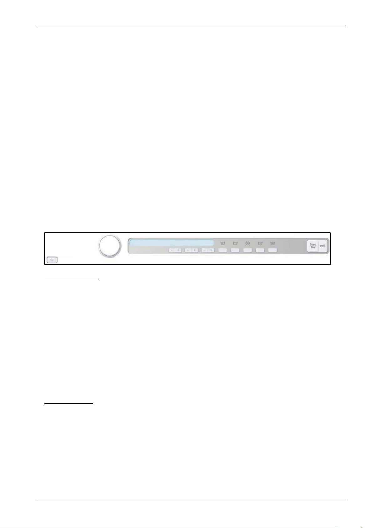
Service manual WM70
This document must not be copied without
our written pemission, and the contents
thereof must not be imparted to a third party
nor be used for any unauthorized purpose.
Contravention will be prosecuted.
Asko Appliances AB
CIRCUIT DIAGRAM WM70.2
80 886 18 - 00
RESISTANCES AT ROOM TEMPERATURE (CA. 20°C/68°F)
VALUES WITHIN +/-10% ARE REGARDED AS NORMAL COMPONENT
F: RADIO INTERFERENCE SUPPRESSION FILTER 680K Ohm
EL: HEATING ELEMENT 25 Ohm
AP: DRAIN PUMP 50 Hz 144 Ohm
AP: DRAIN PUMP 60 Hz 76 Ohm
LL: DOOR LOCK, 1-2 122 Ohm
NTC: THERMISTOR 6.1 - 3.8 K Ohm
IV 1: INLET VALVE 1 3.7 K Ohm
IV 2: INLET VALVE 2 3.7 K Ohm
IV 3: INLET VALVE 3 3.5 K
Ohm
MO: MOTOR, 1-3 4,3±7% Ohm
1-2 4,3±7% Ohm
2-3 4,3±7% Ohm
MCU: MOTOR CONTROL UNIT
N: PRESSURE SWITCH
TS: PRESSURE SENSOR
TG: TACHO GENERATOR
BA: CONTAINER
INKB: INCOMING GROUND
S1
S6S7
S13 S14
TOTAL RESET
TURN OFF POWER (S1)
WAIT FOR AT LEAST 5 SEC
HOLD DOOR OPENING (S14)
TURN ON POWER (S1)
SERVICE MENU
TURN OFF POWER (S1)
WAIT FOR AT LEAST 5 SEC
HOLD S6 OR S7
TURN ON POWER (S1)
PRESS S6 OR S7 3 TIMES TO ENTER SERVICE MENU
PRESS DOOR OPENING (S14) TO CHANGE MENU STEP
ROTATE DIAL TO CHANGE IN STEP
PRESSING START/STOP (S13) STORES AND EXITS SERVICE MENU
STEP 1: PRODUCT DATA
STEP 2: FAILURE DATA
STEP 3: COMPONENT TEST
Wiring diagram WM70.2 cont.
21
Page 22
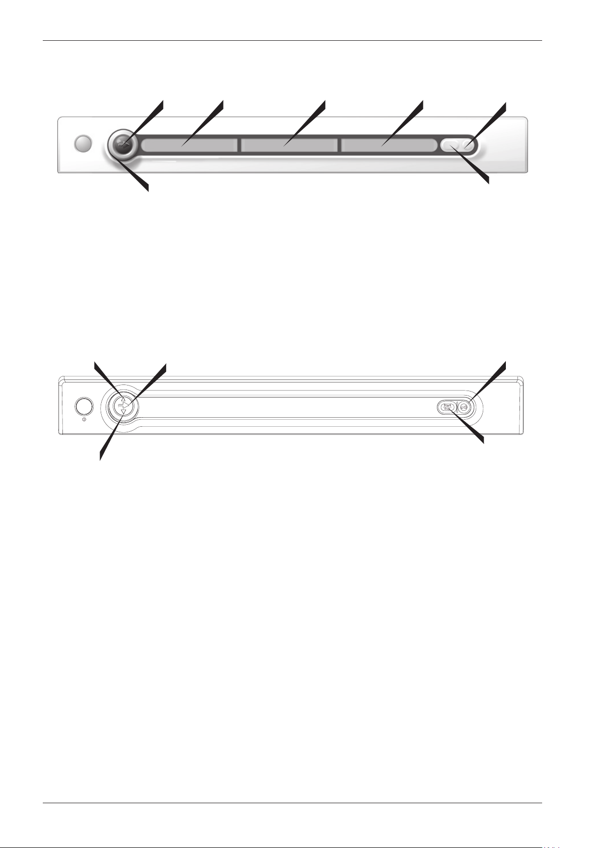
Service manual WM70
Overview: Panel WM70.3
S1
LCD 2
J1
Programs: 14, where one consists of the menu for settings (Program 15)
for V826, it is possible to add a program(stain program)
Options: 6
Settings: 8
S4
S1
LCD 1
LCD 2
LCD 3
LCD 3
S3LCD 1
S2
S3
S5
Programs: 14, where one consists of the menu for settings (Program 15)
for V826, it is possible to add a program(stain program)
Options: 6
Settings: 8
S2
22
Page 23
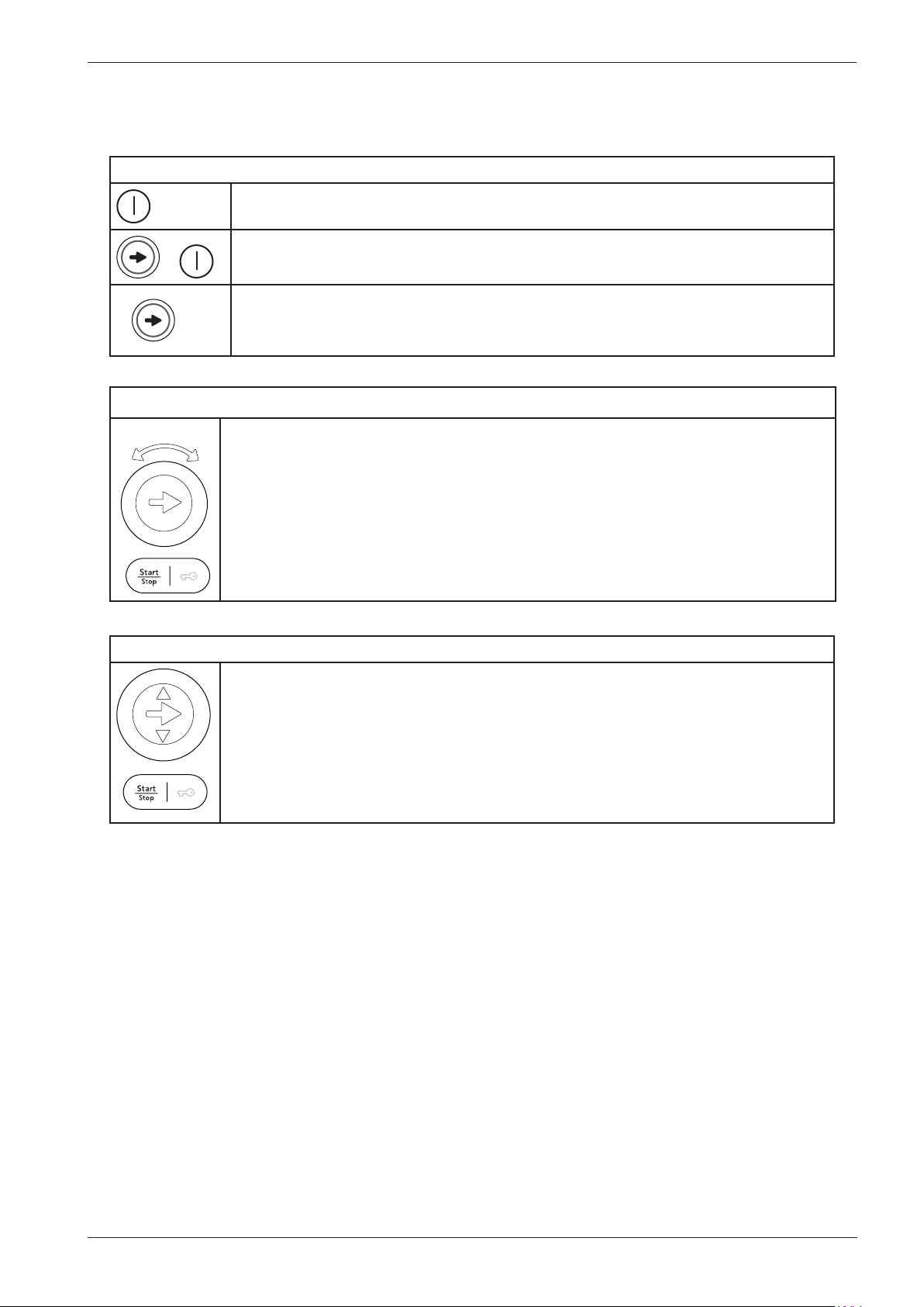
Service manual WM70
Service menu WM70.3
This is how to enter the service menu
If the machine is on: First switch the power off with the main power switch.
Press the program selector (S1) at the same time as the Main power switch.
+
Press the program selector button 3 times within 5 seconds. You are now in
3x
Program selector
2
the service menu (shown in LCD 2. See instructions below for navigating the
service menu.
1. Press the program selector button to scroll between the various service
menus.
2
2. Turn the program selector button to make a selection between the menus
1
(e.g. set a certain water inlet). Confirm the selection and go to the next menu by
3
pressing the program selector button (1).
3. Press the Start/Stop button to confirm the settings and exit the service menu.
Program selector button for integrated machines
2
2
3
1. Press the program selector button to scroll between the various options.
1
2. Press the small arrows to make a selection between the options (e.g. set a
certain water inlet). Confirm the selection and go to the next option by pressing
the program selector button (1).
3. Press the Start/Stop button to confirm the settings and exit the service menu.
23
Page 24
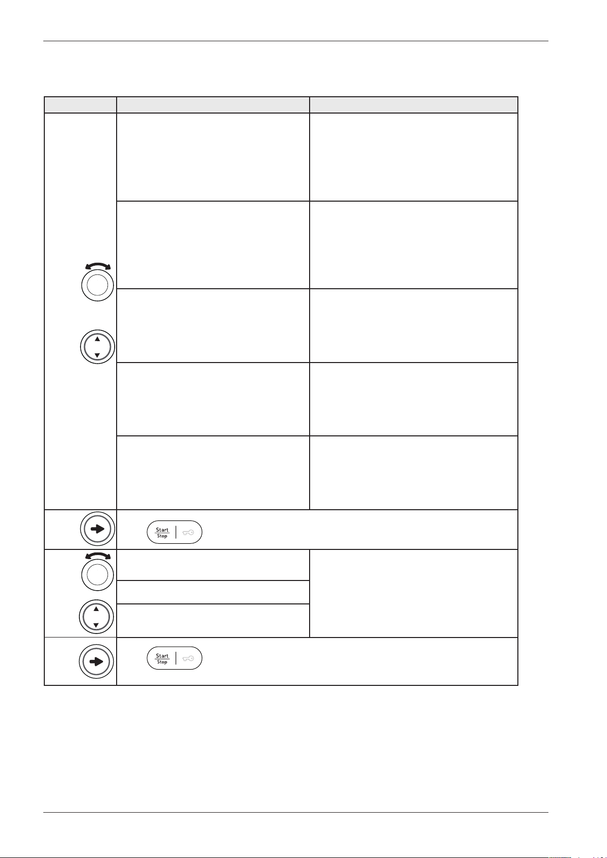
Service manual WM70
Service menu WM70.3 cont.
The options below are displayed in the order they occur in LCD 2. All display text language
versions are displayed.
Press/turn LCD 2 Comments/instructions
DataSerialNo, Data Ser Num,
DataSerialNo, DataSerialNo,
Serienummer, Serienummer, Dataversio
Nro, N° de série, Seriennummer, Num.
di serie, N° de serie, Сeрийный нoмeр,
Serienummer
CU date code, CU Date Code, CU date
code, CU datum kod, CU dato kode,
Styrekort prod dato, CU pvm koodi,
Code date CU, CU Datumscode, Codice
data CU, Código fecha CU, Кoд дaты
БУ, CU datacode
Software1, Software1, Software1,
Mjukvara1, Software1, Software ver.1,
Ohjelmisto1, Logiciel1, Software1,
Software1, Software1, Beрсия пpoг.1,
Software1
Software2, Software2, Software2,
Mjukvara2, Software2, Software ver.2,
Ohjelmisto2, Logiciel2, Software2,
Software2, Software2, Beрсия пpoг.2,
Software2
No. of cycles, Number of Cycles, No.
of cycles, Antal cykler , Antal cyklusser,
Antall bruk, Syklien lkm, Nb. de cycles,
Anzahl der Zyklen, Numero cicli, N° de
ciclos, Кoл-вo циклoв, Aantal cycli
Date for programming the software (Year_
Week)
Control unit’s date of manufacture (Year_
Week)
The software version number of the
software that controls the program flow
The software version number of the
software that controls the display.
Number of cycles/programs run
24
Press to exit the service menu.
”Error_Number of cycles” Last three errors and number of cycles
is shown. Total reset deletes the error
”Error_Number of cycles”
”Error_Number of cycles”
Press
to exit the service menu.
indications from the system. Delete the
error indications by pressing the DOOR
OPENING BUTTON and the MAIN
POWER SWITCH at the same time.
Page 25
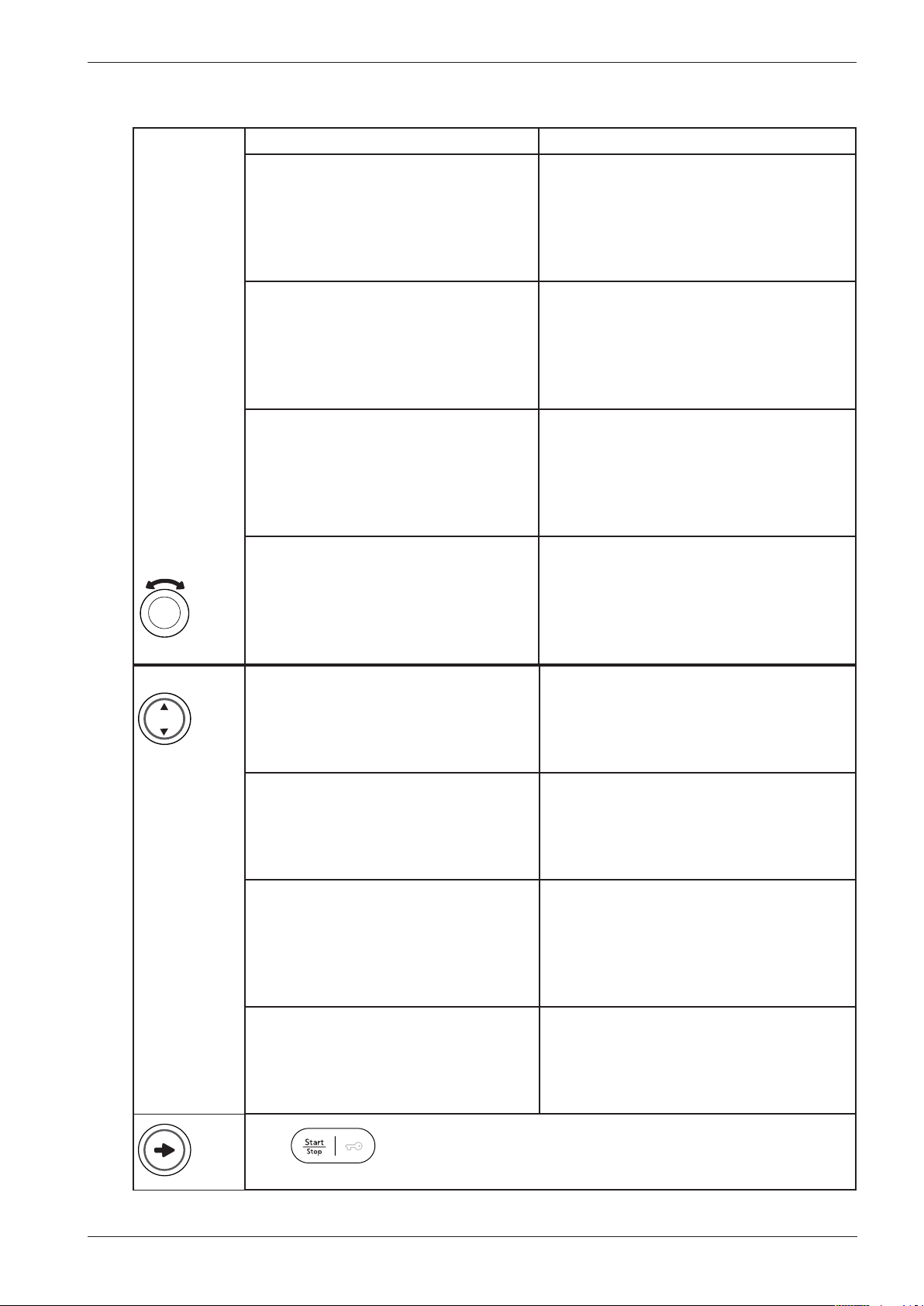
Service manual WM70
Service menu WM70.3 cont.
Testing
Test valve 1, Testing Valve 1, Test valve
1, Ventiltest 1, Tester ventil 1, Test av
vannventil 1, Mg venttiilitesti 1, Essai
vanne 1, Ventil testen 1, Test valvola
1, Test válvula 1, Teст клaпaнa 1, Test
inlaatventiel 1
Test valve 2, Testing Valve 2, Test valve
2, Ventiltest 2, Tester ventil 2, Test av
vannventil 2, Mg venttiilitesti 2, Essai
vanne 2, Ventil testen 2, Test valvola
2, Test válvula 2, Teст клaпaнa 2, Test
inlaatventiel 2
Test valve SM, Testing Valve SM, Test
valve SM, Ventiltest SM, Tester ventil SM,
Test av vannventil SM, Mg venttiilitesti
SM, Essai vanne SM, Ventil testen SM,
Test valvola SM, Test válvula SM, Teст
клaпaнa SM, Test inlaatventiel SM
Test heater, Testing Heater, Test heater,
Elementtest, Tester varmelegeme, Test
av element, Vastustesti, Essai résistance,
Heizung testen, Test elem. riscald., Test
elemento calef, Teст TЭHa, Test verw.
element
Inlet valve 1 is open. Pressure sensor value is
shown in LCD 2.
Inlet valve 2 is open. Pressure sensor value is
shown in LCD 2.
Inlet valve 1 and 2 is open. Pressure sensor
value is shown in LCD 2.
Heater is on until max 60 °C. Thermistor
value is shown in LCD 2.
Test motor, Testing Motor, Test motor,
Motortest, Tester motor, Test av motor,
Moottoritesti, Essai moteur, Motor
testen, Test motore, Test motor, Teст
мoтoрa, Test motor
Test drain, Testing Drain, Test drain,
Tömningstest, Tester udpumpning, Test
av tømming, Tyhjennyspumpputesti, Essai
vidange, Abfluss testen, Test scarico, Test
drenaje, Teст нaсoсa, Test afvoerpomp
Test spin, Testing Spin, Test spin,
Centifugeringstest, Tester centrifugering,
Test av sentrifugering, Linkoustesti,
Essai essorage, Schleudern testen, Test
centrifuga, Test centrifugado, Teст
oтжимa, Test centrifugeren
Test door, Testing Door, Test door,
Dörrtest, Tester luge, Test av dørlås,
Luukun lukon testi, Essai porte, Luke
testen, Test sportello, Test puerta, Teст
зaмкa двeрцы, Test deurslot
The motor is running at normal action (49
rpm).
A Drain pump is on. Pressure sensor value is
shown in LCD 2.
A Spin sequence is performed, the drain
pump is running. Unbalance value is shown
in LCD 2.
Door lock is activated, the door is then
opened.
Press
to exit the service menu
25
Page 26
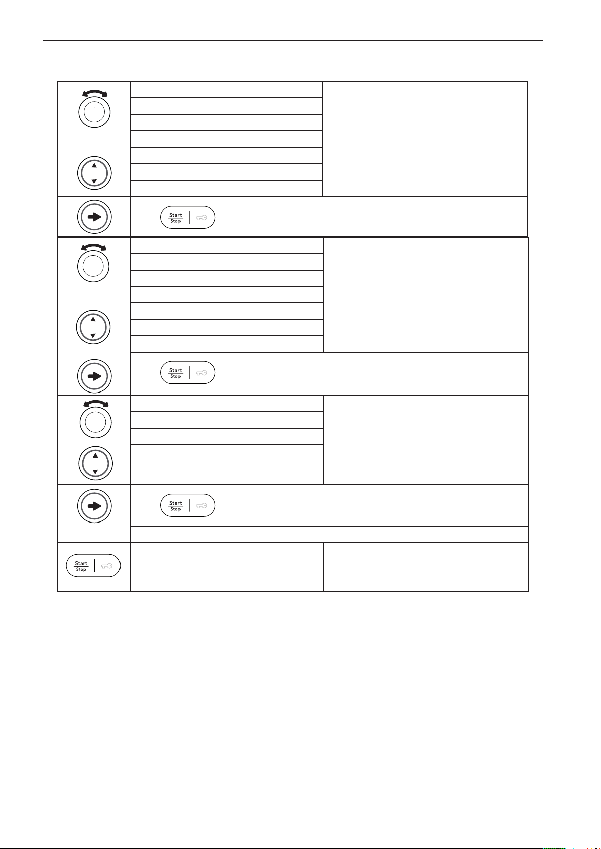
Service manual WM70
Service menu WM70.3 cont.
0
-15%
-10%
-5%
+5%
+10%
+15%
Press to exit the service menu.
-1
-2
-3
0
+1
+2
+3
Setting amount of water taken into the
machine. Default value is ”0”.
Adjust LCD contrast Default value is ”0”.
Press
1500 rpm
1600 rpm
1700 rpm
1800 rpm
Press
Reset
Language US English, English, Svenska, Dansk, Norsk,
to exit the service menu
Setting maximum speed. Default value is
”1600 rpm”.
to exit the service menu.
Suomi, Francais,Deutsch, Italiano, Esoanol,
Русский, Nederlands
26
Page 27
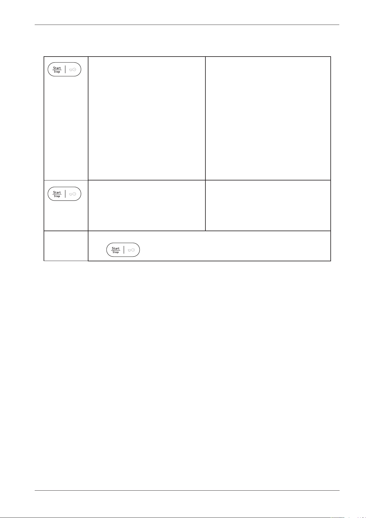
Service manual WM70
Service menu WM70.3 cont.
Clock 24hr Realtime, 24 Hour Clock, 24hr
Transport protection Transport protection, Transport protection,
Realtime, 24 timmarsvisning, 24 timers
ur, 24t realtid, 24 h aika, Horloge 24 h,
24 Std. Echtzeit, 24h Tempo reale, Reloj
24 horas, Фoрмaт врeмeни 24-ч., 24 uur
weergave,12hr Realtime, 12 Hour Clock,
12hr Realtime, 12 timmarsvisning, 12 timers
ur, 12t realtid, 12 h aika, Horloge 12 h,
12 Std. Echtzeit, 12h Tempo reale, Reloj
12 horas, Фoрмaт врeмeни 12-ч., 12 uur
weergave, No Real time, No Real Time, No
Real time, Ej realtid, Intet ur, Ingen realtid,
Ei aikaa, Pas d’horloge, Keine Echtzeit,
No tempo reale, Sin hora real, Время не
установлено, Geen tijdsweergave
Transportskydd, Transportbeskytt.,
Transportvern, Kuljetustuet, Protection
transport, Transportsicherung, Protezione
transporto, Anclaje transport, защита при
транспортирoвke, Transportbescherming
Press
to exit the service menu.
27
Page 28
Service manual WM70
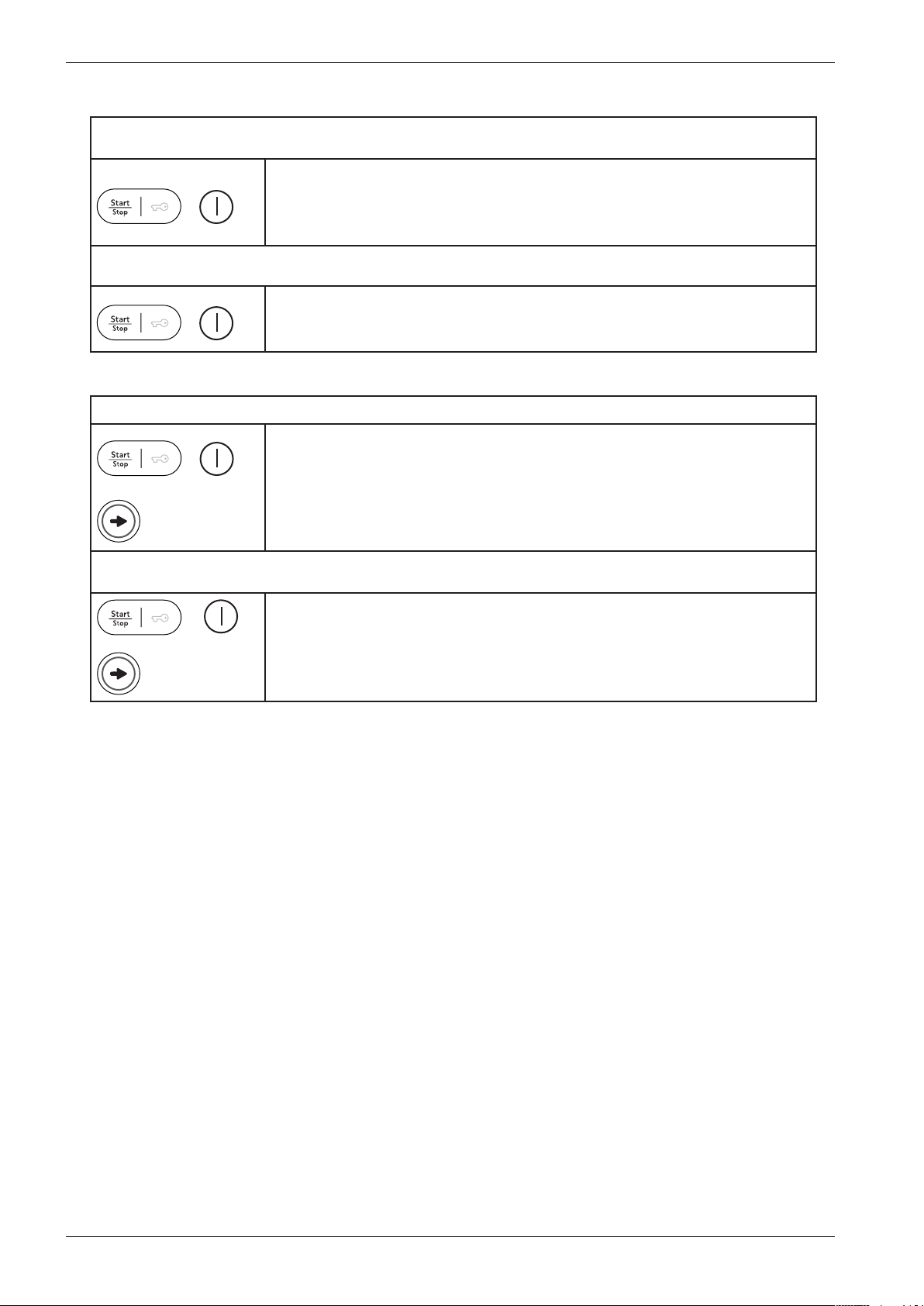
Shop program WM70.3
1. Activating the Shop program (for machines manufactured up to week 736)
If the machine is on: First turn off the power at the main power switch.
Then press and hold the Start button while turning on the main power switch.
+
2. Stopping the Shop program (for machines manufactured up to week 736)
+
1. Activating the Shop program (for machines manufactured from week 737 on)
+
x5
At this point no settings can be made. The centre display will activate after 3
minutes. Settings can now be made, but the machine cannot be started.
First turn off the power at the main power switch.
Then press and hold the Start button while turning on the main power switch.
The Shop program is now stopped.
If the machine is on: First turn off the power at the main power switch.
Then press and hold the Start button while turning on the main power switch.
Press the program selector 5 times At this point no settings can be made. The
centre display will activate after 3 minutes. Settings can now be made, but the
machine cannot be started.
2. Stopping the Shop program (for machines manufactured from week 737 on)
First turn off the power at the main power switch.
+
x5
Then press and hold the Start button while turning on the main power switch.
Press the program selector 5 times.
The Shop program is now stopped.
Store program WM70.2 and WM70.1
There are no store programs on the WM70.2 and WM70.1.
28
Page 29
Service manual WM70
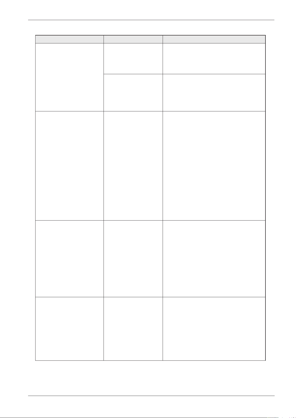
Fault indications WM70.3
The below faults are indicated in plaintext in LCD 1. The table shows the indication in all languages and language variations.
LCD 1 Cause Action
Over flow fault, Overflow
Fault, Over flow fault,
Överfyllnad, Overløbsfejl,
Overflom, Ylitulviminen,
Trop plein, Überfüllt, Troppo
pieno, Desborde, Пeрeлив
вoды, Te veel water
Water outlet fault, Water
Outlet Fault, Water outlet
fault, Uttömningsfel,
Udpumpningsfejl, Vannutløp,
Vedenpoistovika, Défaut ,
Wasserablauffehler, Uscita
acqua, Fallo, Слив вoды,
Waterafvoer fout
Too much water in the
machine.
The drain pump is on,
without any water in the
machine.
1. The drain pump has
been activated more
than 3 minutes. There is
still water in the machine.
2. The wash cycle is
interrupted and the
program is cleared.
Service action:
Check the machine’s level system, inlet valve
and drain pump. Make sure that there is no
leaks.
Service action:
The overflow protection at the bottom of
the machine is activated (not all models).
Make sure that there is no leaks (water on
the machines base)
Customer information:
1. Check that no objects are stuck in the
drainage hose outlet.
2. Check that the drain pump is not blocked
by foreign objects.
3. Check that there are no kinks in the
drainage hose.
Service action:
1 .If the pump only runs for a short while
(approximately 20 seconds), this indicates
a fault in the level system. Check the level
sensor and hoses.
2. Check wiring and voltage to the pump. If
necessary, replace the pump and/or control
3. After implementing corrective action, run
the Drain program or press the Key button
Water inlet fault, Water
Inlet Fault, Water inlet
fault, Vattenintagsfel,
Vandindtagsfejl, Vanntilførsel,
Vika vedenotossa, Défaut,
Wasseraufn.-fehler, Entrata
acqua , Fallo , Haбoр вoды,
Watertoevoer fout
Security fault, Security
Sys Fault, Security
fault, Lucköppningsfel,
Sikkerhedsfejl, Sikkerhetsfeil,
Vika turvajärj., Erreur
sécurité, Sicherh.-fehler, Err.
sis.sicurezza, Fallo sistema
seguridad, Oшибкa сис.
бeзoп., Deurslot fout
If the correct water level
is not reached within 5
minutes, the wash cycle
is interrupted.
The door is open. Close the door.
Customer information:
1. Check that the tap on the water pipe is
open.
Service action:
1. Check that the lter in the machine’s water
intake is not blocked.
2. Check the inlet valve. If necessary, replace
the valve.
3. Check voltage to the inlet valve. If there is
no voltage, this could be due to a fault in the
level system, wiring or control unit.
29
Page 30

Service manual WM70
Fault indications WM70.3 cont.
Fault indications WM70.3
The below faults are indicated in plaintext in LCD 1. The table shows the indication in all languages and language variations.
LCD 1 Cause Action
Thermistor fault, Thermistor
Fault, Thermistor fault,
Termistorfel, Termostat fejl,
Termistor, Termistorivika,
Défaut , Termistorfehler,
Termistore , Fallo ,
Teрмистoр, Temp. sensor
fout
Temperature fault,
Temperature Fault ,
Temperature fault,
Temperaturstoppfel,
Temperatur fejl,
Temperaturstopp, Ei lämmitä
vettä, Défaut , Temp.stoppfehler, Errore arresto
, Fallo , Teмпeрaтурa,
Temperatuurstop
Wash motor fault, Wash
Motor Fault , Wash motor
fault, Motorfel, Motor fejl,
Motorfeil, Moottorivika,
Défaut , Motorfehler, Motore
lavaggio , Fallo , Moтoр,
Motorstoring
1. The circuit for the
thermistor is open.
2. The thermistor is
faulty.
3. The measurment
value for the thermistor
is <300 Ω (>120 °C ).
• The temperature is
raised < 5
°C/41°F within 10
minutes. The
wash cycle continues to
next step.
No signal from Tacho or
MCU.
Service action:
Check the thermistors function. If needed,
replace it.
Service action:
Check the heater, cables, thermistor and
level system.
Service action:
Check signal from the MCU and cables
between motor and MCU.
Pressure fault, Pres Sensor
Fault, Pressure fault,
Trycksensorfel, Tryksensor
fejl, Nivåfeil, Painesensorivika,
Défaut , Drucksensorfehler,
Pressostato , Fallo , Дaтчик
урoвня, Druksensor fout
Unbalance, Unbalance,
Unbalance, Obalans, Ubalance,
Ubalance, Epätasapaino,
Balourd, Unwucht, Non
bilanciato, Desequilibrio,
Дисбaлaнс, Onbalans
After carrying out corrective actions as above, reset the fault indications by pressing the DOOR
OPENING BUTTON at the same time as the main power switch.
Indicated if the level
drops to 0 within 30
seconds of the first
rinsing.
After 10 failed attempets
to spin the load the
machine has stoped to
spin beacuse of to high
umbalance.
Service action:
Check the leakage.
Information to customer:
- Small loads with heavy items can cause this
problem when these articles are difficult to
redistribute.
30
Page 31
Service manual WM70
PERSONAL NOTES
31
Page 32
Service manual WM70
This document must not be copied without
our written pemission, and the contents
thereof must not be imparted to a third party
nor be used for any unauthorized purpose.
Contravention will be prosecuted.
Asko Appliances AB
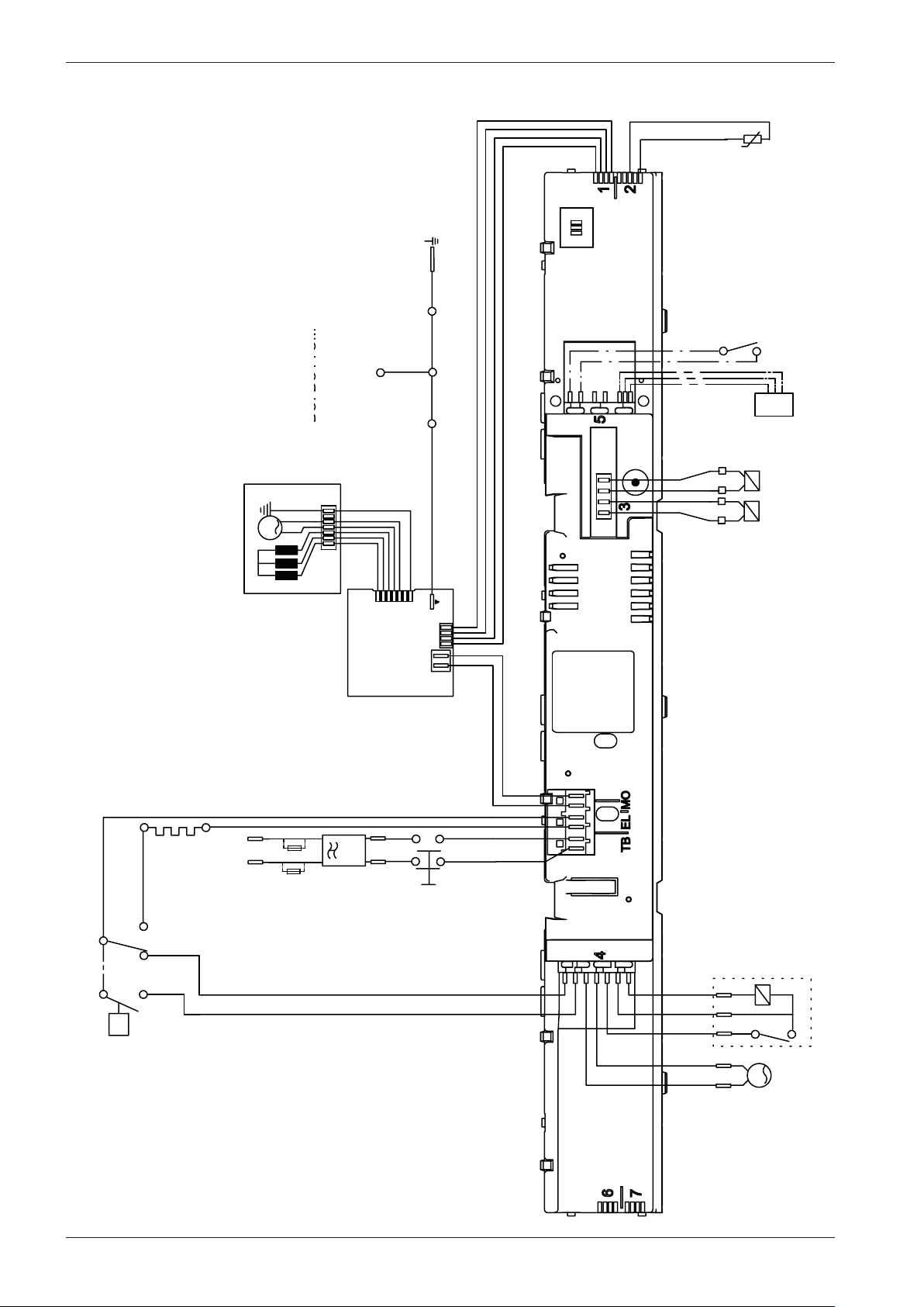
CIRCUIT DIAGRAM WM70.3
80 886 17 - 00
IV 1: INLET VALVE 1 3.7 K Ohm
IV 2: INLET VALVE 2 3.7 K Ohm
MO: MOTOR, 1-3 4,3±7% Ohm
1-2 4,3
±7% Ohm
2-3 4,3
±7% Ohm
Wiring diagram WM70.3
MCU: MOTOR CONTROL UNIT
TG: TACHO GENERATOR
N: PRESSURE SWITCH
TB: MAIN SWITCH
NTC
INKB
FB
EL
FB: FLOAT SWITCH
TS: PRESSURE SENSOR
BA: CONTAINER
INKB: INCOMING GROUND
BO: BOTTOM
BA
BO
TS
TS
IV2
N11
N14
TG
IV1
MO
MCU
EL
N
L
*A
*A
F
6 5
4 3
TB
32
<P
N12
N16
1
2
3
LL
AP
Page 33
Service manual WM70
RESISTANCES AT ROOM TEMPERATURE (CA. 20°C/68°F)
VALUES WITH +/-10% ARE REGARDED AS NORMAL COMPONENT
F: RADIO INTERFERENCE SUPPRESSION FILTER 680K Ohm
EL: HEATING ELEMENT 25 Ohm
AP: DRAIN PUMP 50 Hz 144 Ohm
AP: DRAIN PUMP 60 Hz 76 Ohm
LL: DOOR LOCK 122 Ohm
NTC
INKB
±7% Ohm
±7% Ohm
Wiring diagram WM70.3 cont.
CABLE POSITIONS
1: MOTOR COMMUNICATION
2: THERMISTOR
3: INLET VALVES
4: DOOR LOCK, DRAIN PUMP, PREASSURE SWITCH
TB: POWER
EL: HEATING ELEMENT, PREASSURE SWITCH
MO: MOTOR POWER
WIRES IN ALL MACHINES
INTERNAL CONNECTION
WIRES IN SOME MACHINES
*A FUSE CONNECTION USA & CANADA
RESISTANCES AT ROOM TEMPERATURE (CA. 20°C/68°F)
VALUES WITH +/-10% ARE REGARDED AS NORMAL COMPONENT
F: RADIO INTERFERENCE SUPPRESSION FILTER 680K Ohm
EL: HEATING ELEMENT 25 Ohm
AP: DRAIN PUMP 50 Hz 144 Ohm
AP: DRAIN PUMP 60 Hz 76 Ohm
LL: DOOR LOCK 122 Ohm
NTC: THERMISTOR 6.1 - 3.8 K Ohm
IV 1: INLET VALVE 1 3.7 K Ohm
IV 2: INLET VALVE 2 3.7 K Ohm
MO: MOTOR, 1-3 4,3±7% Ohm
1-2 4,3
2-3 4,3
MCU: MOTOR CONTROL UNIT
TG: TACHO GENERATOR
N: PRESSURE SWITCH
TB: MAIN SWITCH
FB: FLOAT SWITCH
TS: PRESSURE SENSOR
BA: CONTAINER
INKB: INCOMING GROUND
BO: BOTTOM
±7% Ohm
±7% Ohm
CIRCUIT DIAGRAM WM70.3
80 886 17 - 00
This document must not be copied without
our written pemission, and the contents
thereof must not be imparted to a third party
nor be used for any unauthorized purpose.
Contravention will be prosecuted.
Asko Appliances AB
33
Page 34
Service manual WM70
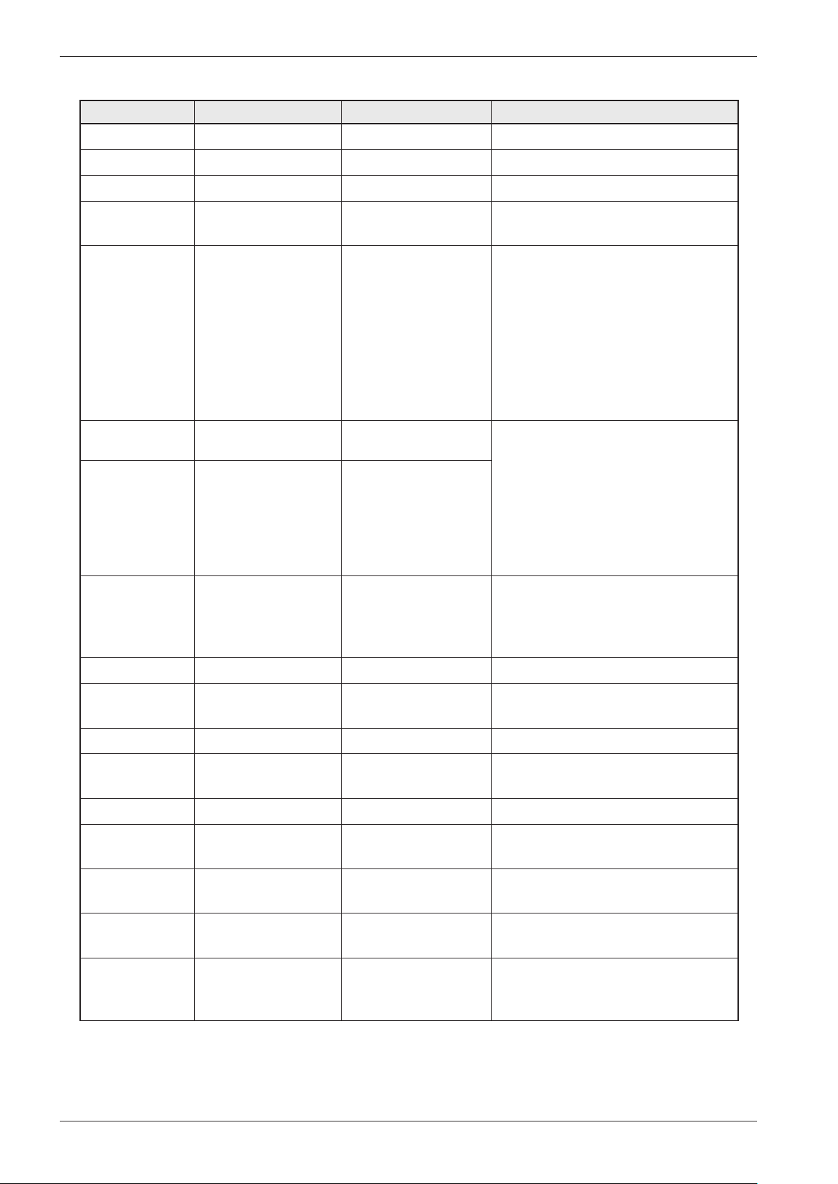
Components and measurement values WM70
Item number Component Measurement value Comments
80 886 44 CIM-motor See wiring diagram
80 886 42 UM-Motor 50 Hz See wiring diagram
80 886 43 UM-Motor 60 Hz
80 617 06 Heating element
2000 W
88 014 74 Thermistor compl. w.
holder
88 012 63 Drain pump 50 Hz See wiring diagram The drain pump is combined with an
88 012 64 Drain pump 60 Hz See wiring diagram
80 782 21 Level switch Electro mechanical level switch
See wiring diagram
See wiring diagram The thermistor for temperature
reading is located between the
motor cradle and the container. The
thermistor measures and controls
the water temperature that can vary
from 0 to 90°C / 194°F. The element
is disconnected if the thermistor is
short-circuited or disconnected from
the program control card.
integrated fine filter trap, which can
be cleaned by the user. If the drain
pump has run for 180 seconds during
draining, the program stops, resets
and a fault code is indicated in the
display. The drain pumps capacity is
20 liters/min.
with two levels, see wiring diagram.
Indicates levels for door opening, heat
and overfilling
80 897 65 Level switch, WM70.1
80 762 02 EMC-Filter with
inductor
80 838 80 Inlet valve See wiring diagram 2 way inlet valve 8 litres / minute
80 798 73 Door lock See wiring diagram The door lock is electro mechanical
88 014 40 Control unit WM70.3
88 014 41 Control unit WM70.3
FI
80 896 72 Motor Control Unit,
WM70.2
80 896 73 Motor Control Unit
WM70.1, WM70.3
80 928 56 Fuse, Motor Control
Unit
18A 250V 5X22
See wiring diagram The filter eliminates interference to
and from the machine
and equipped with a magnet.
34
Page 35
Service manual WM70
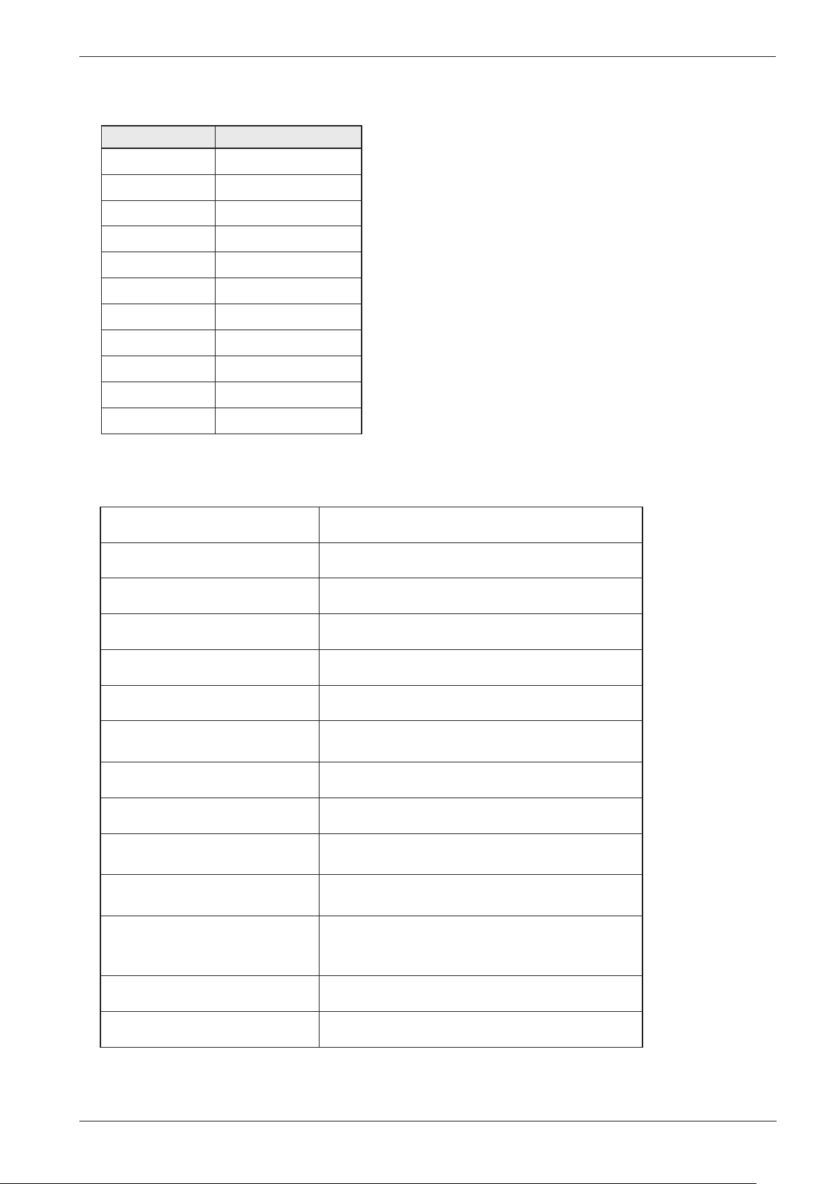
Thermistor measurement values WM70
Temp, º C Resistance, Ohm
0 15806
10 9634
20 6046
25 4841
30 3900
40 2579
50 1744
60 1204
70 848
80 609
85 519
Technical data WM70
Height: 850 mm
Width: 595 mm
Depth: 585 mm
Weight: 77 kg / 81 kg (with outer door)
Cylinder volume: 60 l
Max. washing capacity EU 7,0/8,0kg, AU 7,0kg US 7,0/8,0kg Swan 6,0 kg
Spin speed: WM70.3 400–1800 rpm, WM70.2 400–1800
rpm, WM70.1 400 –1600 spm
Connection: 1 phase 10 A
Element power: 2000W, 230V (See Type designation)
Water pressure/inlet valve: 0,1 – 1 MPa., 1 – 10 kp/cm2, 10 – 100 N/cm2. 8
litre/min
Wash drum and liquid
compartment material:
Outer casing material: Powder coated and galvanized sheet steel or
Stainless steel
stainless steel
Set-up: Stationary on four adjustable, rubber-covered feet
Water connection: 1,5 m pex pipe, 3/4” – 3/4” eller 3/4” – 1/2”
35
Page 36
Service manual WM70
Technical data WM70 cont.
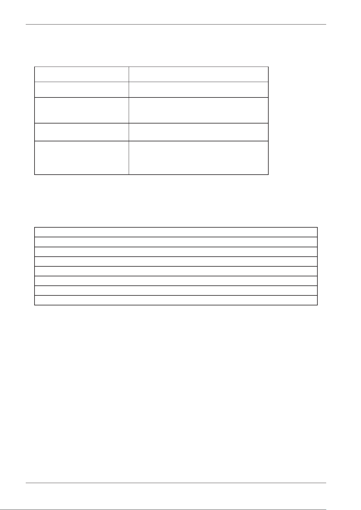
Technical data WM70
Drain: 1,7 m polypropylene tube
Protection class: IP X4
Water consumption (tested
normal program)
Energy consumption (tested
normal program)
Electricity consumption, Standby:
- Main power switch off
- Display on
- Display off
65 litre (3-rinse), <78 litre (5-rinse)
8kg: 1,2kWh, 6kg: 1,14kWh
<0,3 W
<6,0 W
<3,0 W
Tools
Torx; T25, T20, T10
Socket screwdriver 10 mm
5mm socket head cap screwdriver + small locking handle
Ring spanners; 11/16’’, 16mm, 13 mm, 10 mm
24mm extended socket + locking handle
Plastic hammer
Star socket head screwdriver
A pair of nippers
36
Page 37
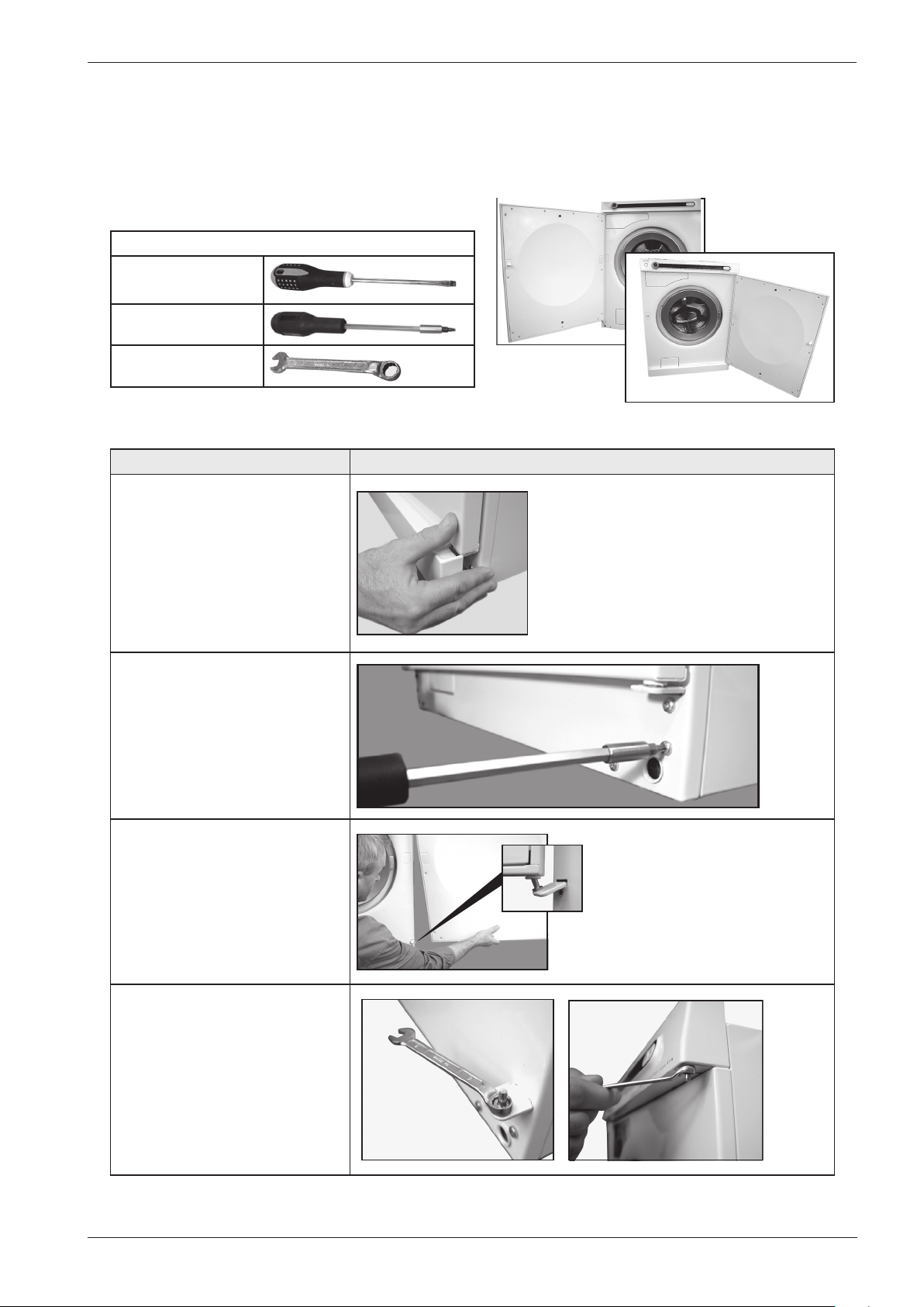
Service manual WM70
Rehanging the door
Some machines in the WM60-series is supplied with a door - is that the case the door is hung on
the left-hand side. It is, however, possible to re-hang it according to the instructions below. Take
care not to damage the paint when carrying out work with tools.
Required tools
Flathead screwdriver
Torx size 20
Fixed spanner size 8
Instructions Image
1. Remove the plinth by carefully
pulling it out.
2. Remove both screws for the
lower hinge. Use Torx.
3. Push the door upwards with
care and angle outwards. If
necessary, carefully press the
lower hinge to detach the door.
4. Slacken off the lower and
upper hinge pins using a fixed
spanner.
37
Page 38
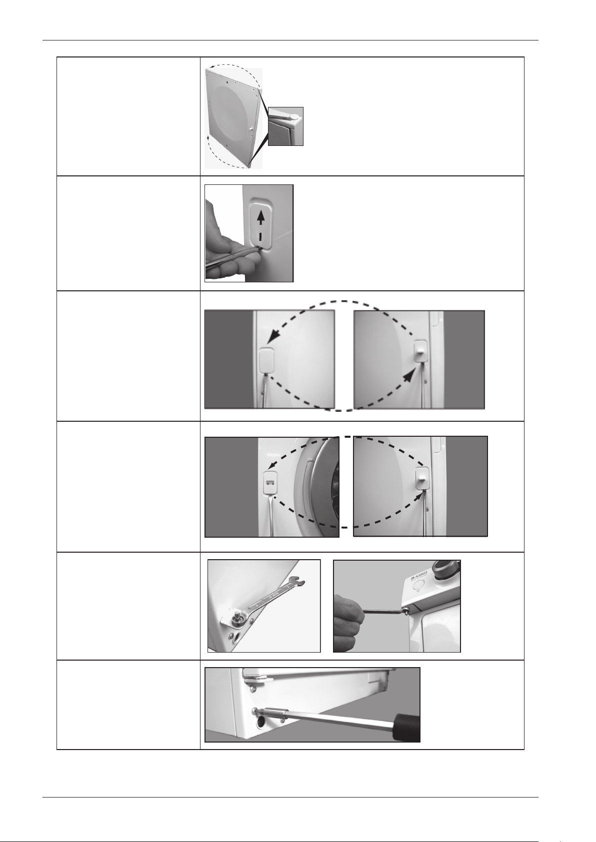
Service manual WM70
5. Remove the plastic plugs
covering the holes for the
hinge pins and switch location
Method for removing plastic
plugs, lock and catch located
on the machine and the door:
Carefully push the plug, catch
or lock upwards with a flat
screwdriver. as the picture
shows.
6. Carefully remove the catch
and plastic plug on the door
(according to the method
above) and switch location.
7. Carefully remove the
lock and plastic plug on the
machine (according to the
method above) and switch
location.
8. Screw the hinge pins
securely into place on the
corresponding side of the
machine.
9. Slacken off the screws
for the lower hinge on the
corresponding side of the
machine. This must be done
to hang the door.
38
Page 39
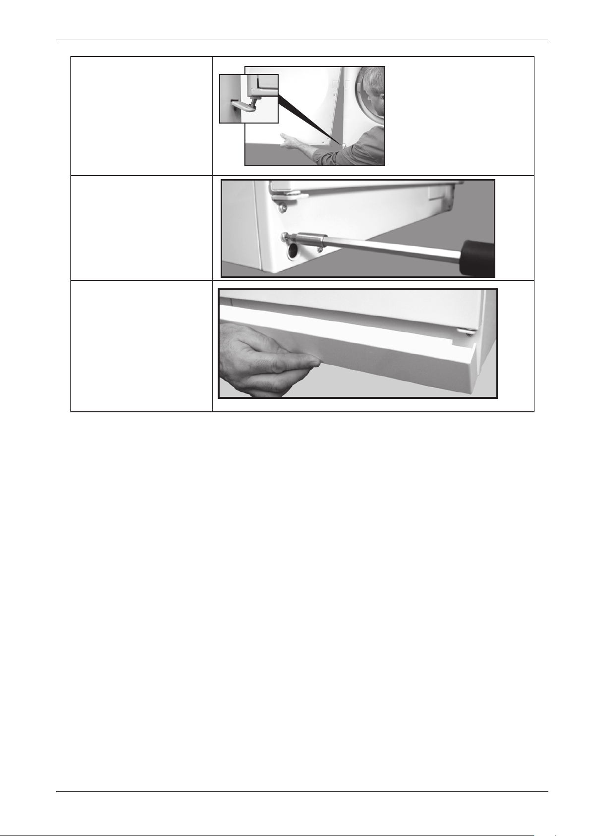
Service manual WM70
10. Align the door in the
upper hinge. Carefully push
the lower hinge down if
necessary and align the door.
11. Screw the lower hinge into
place securely. Use Torx.
12. Press the plinth into place.
The door has now been rehung.
39
Page 40
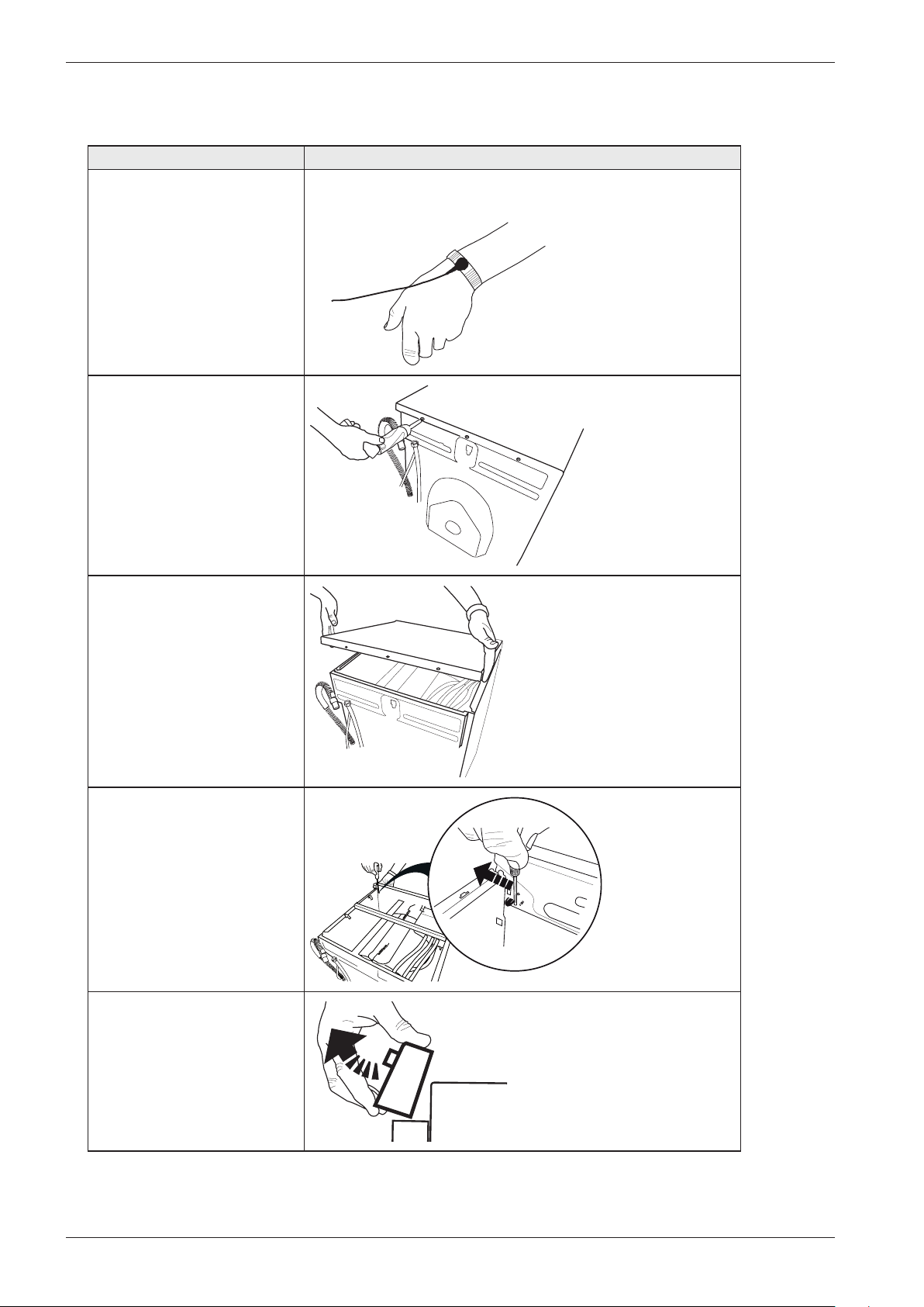
Service manual WM70
Replacing panels, control unit and detergent compartment
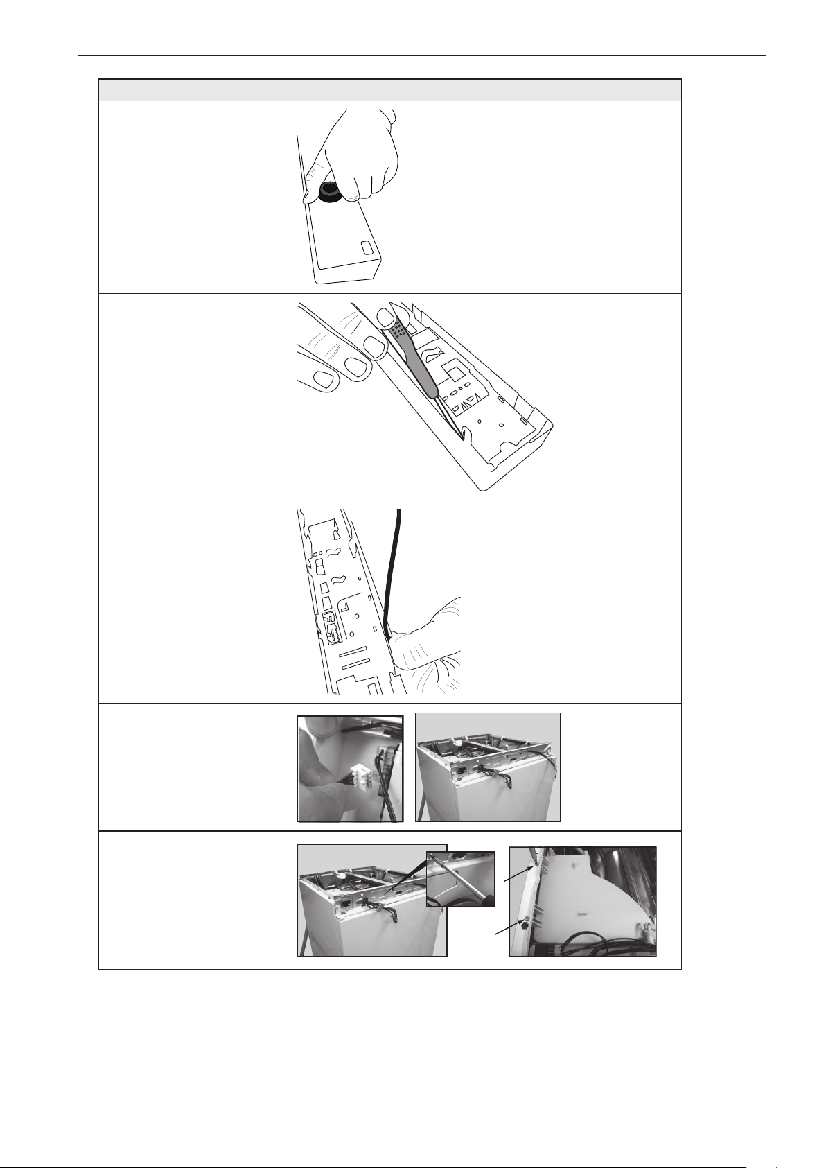
Instruction Image
1. Attach the anti-static
wristband to a part of the
machine that is earthed!
NOTE! An anti-static
wristband must be used,
otherwise you risk destroying
the control card.
2. Unscrew the top cover..
3. Remove the top cover.
4. Use a screwdriver to
carefully free the panel. As
you do so, carefully angle the
panel outwards.
5. Remove the panel and the
cables. NOTE! Don’t forget
to remove the pressure
sensor tube.
40
Page 41
Service manual WM70
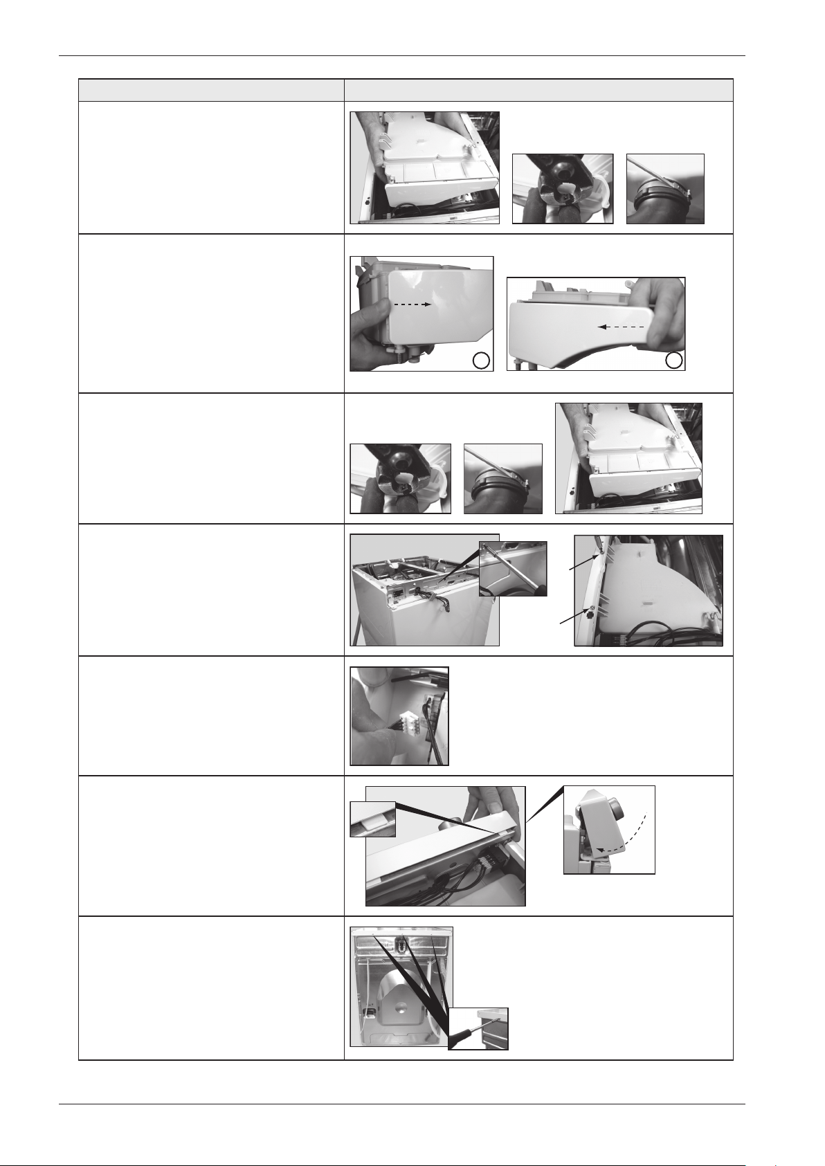
Instruction Image
6. Carefully pull the
programme selector from the
panel.
7. Use a screwdriver to free
the control card from the
panel. NOTE! The control
card must be placed in an
ESD-safe bag.
8. Check that the push
button, lens and decorative
inlay are in place. Now
carefully press the new
control card into place.
NOTE! Don’t forget to
replace the rubber seal.
9. Carefully disconnect the
wiring from the control unit.
10. When removing the
detergent container, first
slacken off the screw on
the front member and then
the two screws holding the
detergent container in the
side panel.
41
Page 42
Service manual WM70
Instruction Image
11. Lift the detergent compartment.
Then remove the hose clamps for all
hoses, which are secured in the detergent
container. Then detach the hoses from
the detergent compartment.
12.If necessary: Replace the decor panel
for the detergent compartment. Detach
the decor panel by pressing according to
image 1. Install the decor panel by first
placing the decor panel in the grooves
on the detergent container and then
snapping it into place as illustrated in
image 2..
13. Install the detergent compartment by
first pressing all hoses into place and then
securing them using the hose clamps.
1
2
14. Screw the detergent compartment
into place using the three screws (one in
the front panel and two in the frame)
15. Install all wiring in the relevant
locations on the control card.
16. Install the panel. Angle the panel
outwards and place the mounting plates
in the relevant grooves in the front frame.
Angle the panel downwards and secure it
with the catches.
17. Screw the top cover into place.
42
Page 43
Service manual WM70
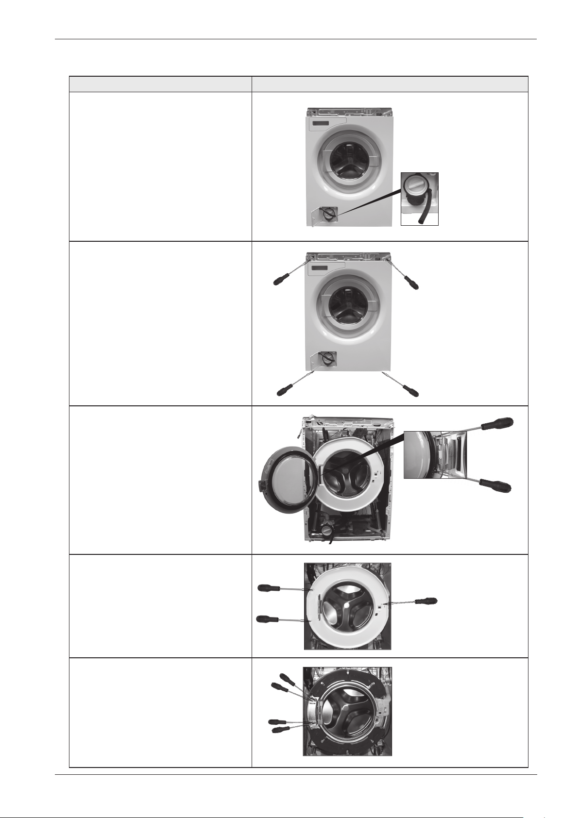
Replacing front panel, door, cover plate and the hinges
Instruction Image
1. Carefully pull off the drainage hose
that is secured in the door for the
drain pump.
Note!
Water is poring out when the
drainage hose is pulled off.
2. Unscrew the screws holding the
front panel. Then remove the front
panel by carefully pulling it out at the
lower edge.
3. Unscrew the two screws holding
the glass door. Use Torx.
4. Unscrew the three screws that
hold the covering plate to the
container. Use a Torx driver. Fully
open the hinge and remove the cover
plate.
5. Unscrew the three screws that
hold the cover plate to the container.
Use Torx.
43
Page 44
Service manual WM70
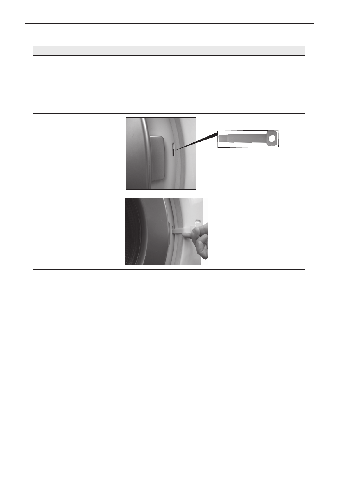
Emergency opener for door lock
Instruction Image
1. The emergency opener is in
the documentation kit.
2. Push the emergency opener
into the slot beside the glass
door.
3. Push the emergency opener
upwards. and the door will
open
44
Page 45
Service manual WM70
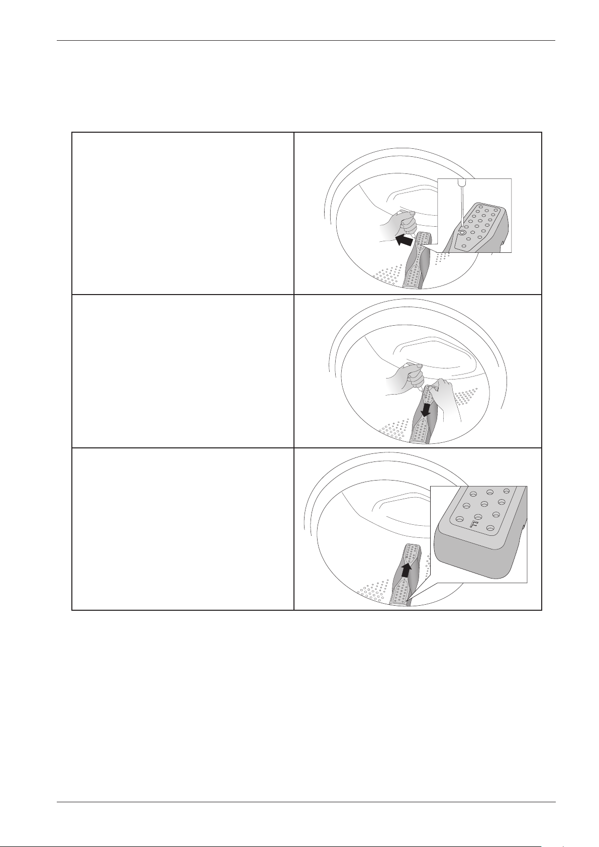
Wash agitator removal
When replacing or cleaning the wash agitators, or when removing items that have fallen through
the wash drum, first you need to remove the agitators. Follow the instructions below.
1. Insert a screwdriver or the like into
the hole on the agitator as illustrated and
carefully pry to the left.
2. Use your other hand to grasp the agitator
and pull it towards you.
3. Lift the agitator.
4. Remove any foreign objects.
5. Place the agitator in the mounting hole
with the letter F towards you. Ensure that
all the agitator fasteners are in their holes
in the drum. Push it away from you until it
fastens.
45
Page 46
Service manual WM70
PERSONAL NOTES
46
Page 47
Service manual WM70
PERSONAL NOTES
47
Page 48

8090803 Servicemanual WM70 EN Ver03
 Loading...