

Page 1
Page 2
SMCWUSBT-G
Wireless USB 2.0 Adapter
802.11b/g (108 Mbps)
User’s Manual
Version 1.02.000
July 11, 2005
Page 3

Contents
ii
Page 4

Wireless USB 2.0 Adapter
CCooppyyrriigghhtt NNoottiiccee
© 2005 All rights reserved. No part of this document may be reproduced or transmitted in any form or
by any means, electronic or mechanical, for any purpose, without the express written permission of the
seller.
DDiissccllaaiimmeerr
Information in this document is subject to change without notice. The statements, configurations,
technical data, and recommendations in this document are believed to be accurate and reliable, but
are presented without express or implied warranty. The seller therefore assu mes n o res po ns ib ili ty an d
shall have no liability of any kind arising from the supply or use of this document or the material
contained herein.
SSttaatteemmeenntt ooff CCoonnd
In the interest of improving inte rnal design, ope rational funct ion, and/or reli ability, the seller reserves
the right to make changes to the products described in this document without notice.
The seller does not assume any liability that may occur due to the use or application of the product(s)
or circuit layout(s) described herein.
In addition, the program and information contained herein are licensed only pursuant to a license
agreement that contains restrictions on use and disclosure (that may incorporate by reference certain
limitations and notices imposed by third parties).
d
iittiioonnss
TTrraaddeemmaarrkkss
All other product or service names mentioned in this document may be trademarks of the companies
with which they are associated.
iii
Page 5

Contents
Contents
Before Y ou Use..................................................................... ................... ................ ....vi
Packing List......... ............................................... ....................................................vi
System Requirements............................................................ .... ... .... ........ .... .... .... .vi
Notes and Cautions ........................................... ....................................................vi
Chapter 1 Overview.......................................... .... .... ........ .... .... ....... .... .... .... ........ .... .1
Wireless LAN Basics...................................................................... ....... ........ .........1
Local Area Network (LAN) ...............................................................................1
Ad Hoc Mode .............................................................................. .....................1
Infrastructure Mode..........................................................................................2
Roaming.......................................................................................................... .2
General Specification.............................................................................................3
Chapter 2 Software Installation.................................................................. .... .... .....5
Installing Wireless Adapter Driver and Utility.........................................................5
Chapter 3 Utility Configuration .............................................................. .... ........ ...11
Action Tab .......................................................................... ............... ................ ...15
Options Tab........................................................................ ............... ................ ...15
Help Tab......................................... .................... ................ ............... ................ ...16
Current Status Tab ......................................... .... ........ .... .... ........ ... .... .... ........ .... ...16
Advanced Tab ................................................................................. ...............17
Profile Management.............................................................................................19
Creating or Modifying a Configuration Profile................................................19
iv
General Tab.............. ................ ................ .................... ............... ................ ...20
Security Tab ..................................................................... ............... ...............20
Advanced Tab ................................................................................. ...............22
Page 6

Contents
Import and Export Profiles .............................................................................25
Order Profiles.................................................................................................26
Scan Available Networks ......................................... ......................................27
Remove a Configuration Profile.............................................. ........ .... .... .... ...27
Diagnostics Tab.......................... .................... ................ ............... .................... ...28
Adapter Information Button............................................................................28
Advanced Statistics....... ... .... ........ .... .... ........ .... .... .... ....... .... .... ........ .... .... .......29
Appendix A Regulatory Compliance....................................................................30
Appendix B EC Declaration of Conformity …………………………………………..32
v
Page 7
Before You Use
Before You Use
For brevity, throughout this manual USB Wireless LAN Card is used to indicate all the types. Also, the
following terms/abbreviations are used interchangeably:
Packing List
Before using the wireless USB 2.0 adapter, check all the following items are present and in good
condition. If any of the items is damaged or missing, contact your retailer immediately.
9 Companion CD x 1
9 Wireless USB 2.0 adapter x 1
System Requirements
To use the Wireless LAN Card, your computer must meet the following minimum requirements:
z Laptop/ PC containing:
9 32-bit CardBus slot (or Desktop PC with PC Card-PCI adapter)
9 Mini PCI
9 32 MB memory or greater
9 300 MHz processor or higher
9 Hard disk space at least 30 Mbytes
z Microsoft Windows 2000, Windows Millennium Edition, Windows 98 Second Edition,
Windows XP, or Windows NT 4.0 (with Service Pack 6)
Notes and Cautions
Note and Caution in this manual are highlighted with graphics as below to indicate important
information.
Note
Caution
This User’s Manual contains information on how to install and configure your USB Wireless LAN Card.
From now on, we will guide you through the correct configuration steps to implement your device.
Contains in formation that corresponds to a specific topic.
Represents essential steps, actions, or messages that should not be
ignored.
vi
Page 8

Chapter 1: Overview
Chapter 1 Overview
This product is an IEEE 802.11b/g Wireless LAN Card with USB interface solution. This solution provides
compatibility with 802.11b and 802.11g standard devices. Now users have the flexibility to connect to
802.11b or 802.11g networks effortlessly.
It allows your computer to co nnect to a wireless network and to sh a re resou r ce s, such a s fil es o r pr inte rs
without being bound to the network wires. Operating in 2.4GHz Direct Sequence Spread Spect rum
(DSSS) radio transmission, the Wireless LAN Card transfers data at speeds up to 54Mbps. Both A d hoc
and Infrastructure mode are supported. For network security concern, 64/128-bits Wired Equivalent
Privacy (WEP) encryption is used. In addition, its standard compliance ensures that it can communicate
with any 802.11b/g networks. It also supports Microsoft WHQL software for Windows XP.
Wireless LAN Basics
This section contains some Wireless LAN basics to help you better understand how the products work
together to create a wireless network.
Local Area Network (LAN)
LAN is a local network that exists in a relatively limited area. Within the network, two or more computers
are connected together sharing files and peripheral devices such as printers.
The Wireless LAN Card allows you to interact with other computers without having to run cables
normally associated with networks. This lets you move your computer around while staying connected to
your network.
There are two ways to use the Wireless LAN Card. One way is to co nnect directly to one or more
Wireless LAN Card equipped computers, forming an Ad hoc wireless network. The second way is to
connect to an Access Point that gives you access to an existing wired LAN, forming an Infrastructure
wireless network.
Ad Hoc Mode
An Ad Hoc network offers peer-to-peer connections between wireless stations that are in range of each
other. The stations communicate directly with each other without using an Access Point or any
connection to a wired network. This mode is useful for quickly and easily setting up a wireless network
anywhere that a wireless infrastructure does not exist or is not required for services. In an Ad Hoc
network, all wireless stations must have the same SSID, channel and WEP keys (if enabled) to
communicate with each other.
1
Page 9
Wireless USB 2.0 Adapter
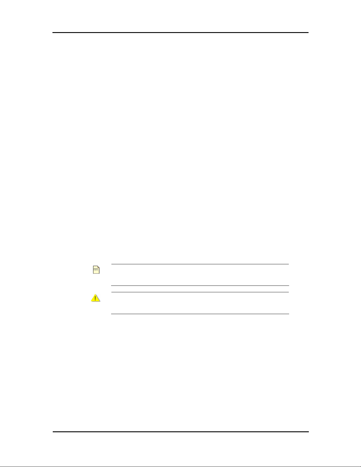
Infrastructure Mode
An Infrastructure wireless network consists of at least one Access Point connected to the wired network
infrastructure and a set of wireless end stations. The AP acts as a gateway, linking the wireless network
to a wired LAN. As a result, wireless stations have access to all of the features of your wired LAN
including e-mail, Internet, network printers and files server access.
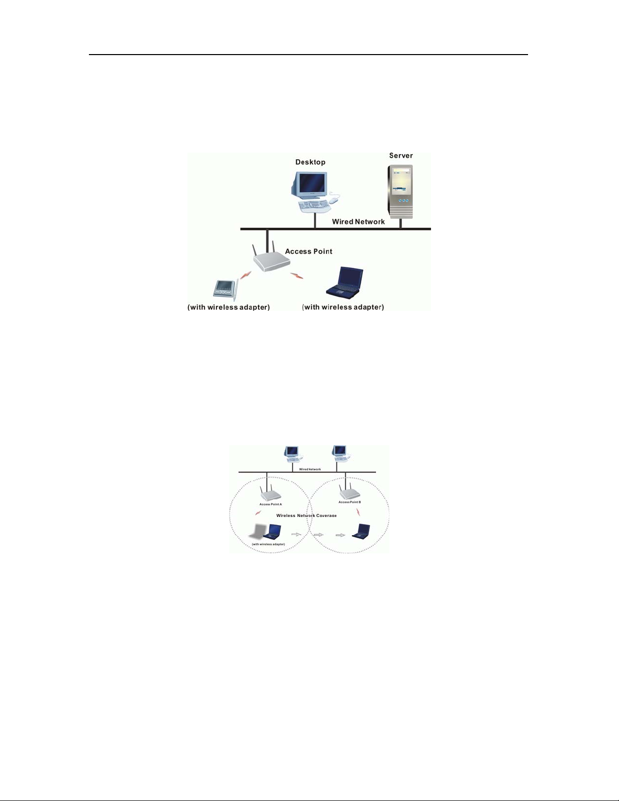
Roaming
For large environments, multiple Access Points can be implemented to extend the wireless service
coverage area for seamless wireless access. It allows wireless clients to roam from one AP to another
while maintaining the wireless connectivity at all times. A wireless client wandering across multiple APs
will automatically change the operating radio frequency as required.
In a roaming network, all APs and wireless clients must have the same Service Set Identity (SSID) and
security setting (if enabled). Alternatively the mobile station may use an SSID of “any” to associate with
any available AP, regardless of the AP’s SSID. Roaming among different Access Points is controlled
automatically to maintain the wireless connectivity at all times.
2
Page 10

General Specification
Chapter 1: Overview
Host Interface
Form Factor
Chipset
Operation Voltage
Network Standard
Hardware Encryption
Quality of Service
Network Architectures
USB Wireless Module
A THEROS AR5523A + AR21 12A
IEEE 802.11b / IEEE 802.11 g
Ad hoc / Infrast r uc t u r e
USB 2.0
5.0VDC
AES, TKIP ,and WEP
802.11e draft
Modulation Technology OFDM with BPSK, QPSK, 16QAM, 64QAM
DBPSK, DQPSK, and CCK
Media Access
Technique
CSMA/CA
Supported Data Rates IEEE 802.11b: 1 – 11 Mbps
IEEE 802.11g: 1 – 54 Mbps
Atheros Super G Mode: up to 108 Mbps
Antenna Type
OS Compatibility
Client Utility
WIN 98SE, WIN ME, WIN 2000, and WIN XP
Automatic location profile, site monitor, current link status, and
Printed PCB antenna
diagnostics
3
Page 11

Wireless USB 2.0 Adapter
4
Page 12
Chapter 2: Software Installation
Chapter 2 Software Installation
This chapter describes how to install the USB Wireless LAN Card driver and utility. Windows 98, ME,
2000, and XP use the same setup program; however, operation system-specific situation may occur
during or after the installation process. The following describes only the overall installation procedure. In
OS-specif ic s ituations, you should follow the on-screen instruct i o ns to proceed. You can ref er to the
general guidelines provided in next section for further information.
In case you need to re-install the driver and software for any reason, we recommend that you remove
any previously installed driver and software from your system first. Refer to Chapter 6 for uninstallin g the
Wireless LAN Card driver and utility, following the instructions to remove previous driver release.
Installing Wireless Adapter Driver and Utility
The software you are ready to install comprises this adapter’s driver and utility. Thus, the following
instructions will guide you through overall installation procedure. In OS-specific situations, you should
follow the on-screen instructions to proceed. For the details, please read the user’s manual.
If your computer’s operating system is Windows XP that is installed with
Note
Follow these steps below to install the wireless adapter driver and utility.
Service Pack 1 only, it is recommended to further install Windows XP
Hotfix – KB822603.
1. Close all Windows programs that are running.
2. Insert the Utility CD into your CD-ROM drive and double click Setup.exe in the companion CD.
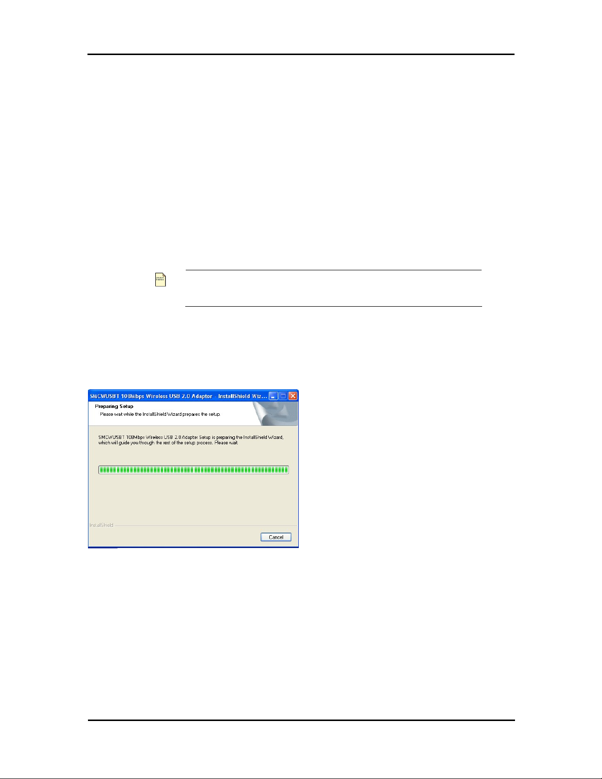
3.
After you double click Setup.exe in the companion
CD, a Preparing Setup windo w appears, and you
may go to a next step when the processing bars
end.
5
Page 13
Wireless USB 2.0 Adapter
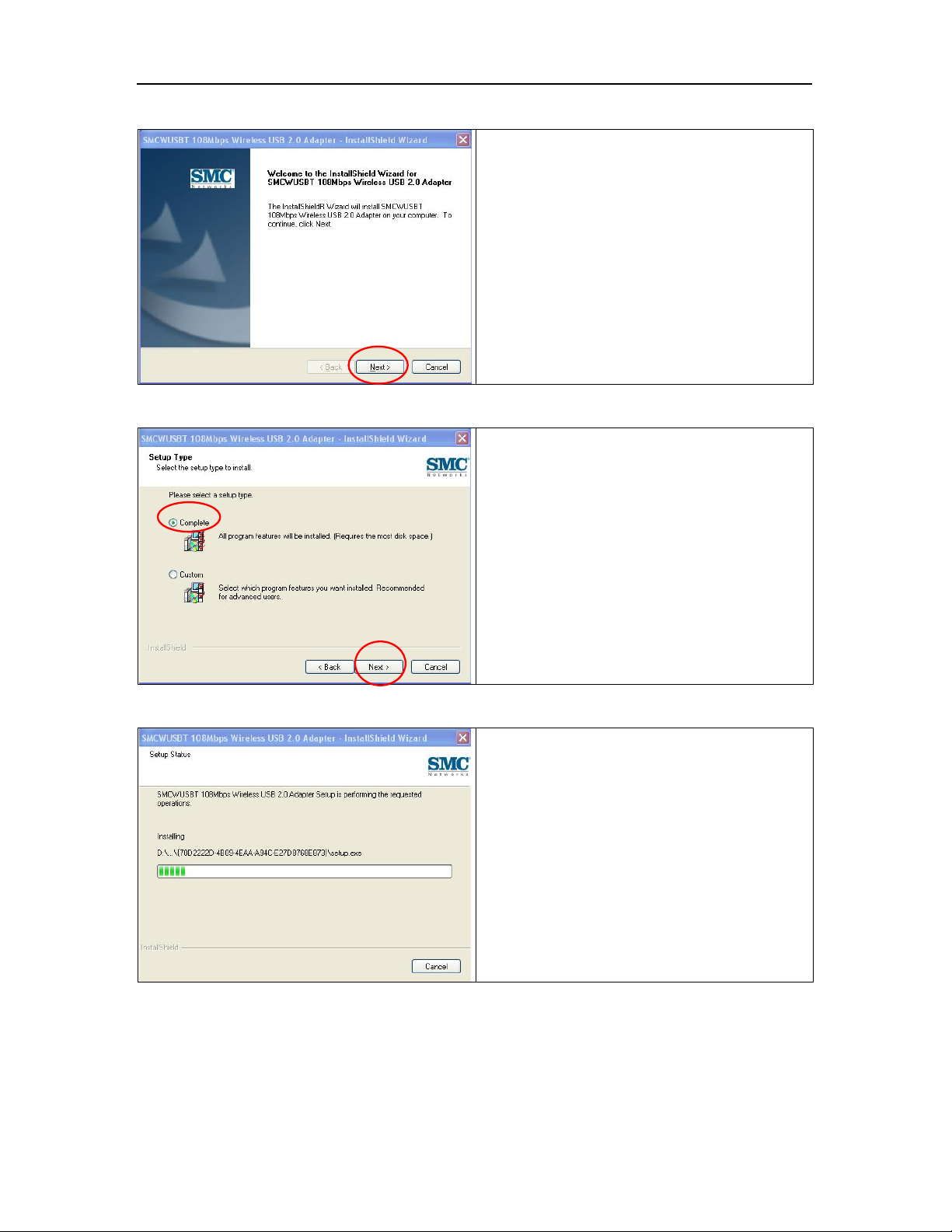
4.
5.
When the welcome screen pops up, click Next.
Please select Complete and click Next.
6.
6
Now, you see processing bars increasing during
installation. Installation progress takes a few
minutes.
Page 14

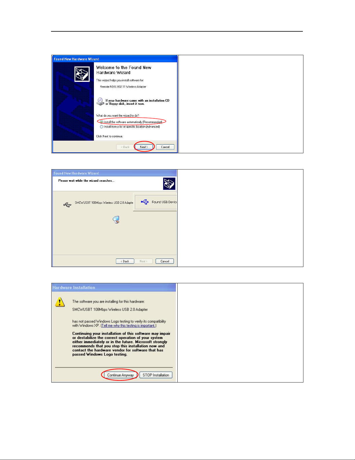
7.
8.
Chapter 2: Software Installation
During installation, a warning window pops up. C lick
Continue Anyway to continue the installation work.
Plug in your wireless USB 2.0 adapter when the
screen pops up.
9.
The USB device you inserted is found.
7
Page 15
Wireless USB 2.0 Adapter
10.
11.
System checks for new hardware and meanwhile
the Found New Hardware Wizard screen pops
up. Choose Install the software automatically
(Recommended) and then click Next.
After clicking Next at the previous step, you will see
a window showing you Please wait while the
wizard searches….
12
8
While the wizard is running, a Hardware
Installation warning window pops up. Then, click
Continue Anyway to continue the installation.
Page 16
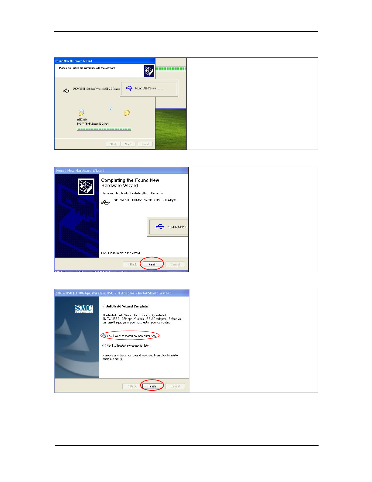
13.
14.
Chapter 2: Software Installation
The wizard is installing the driver. It may take
several minutes.
This adapter’s driver installation is completed.
Click Finish to complete the installation process.
15.
Finally, you are asked to reboot your computer. It
is recommended to restart your computer now, or
you may restart it later.
9
Page 17
Wireless USB 2.0 Adapter
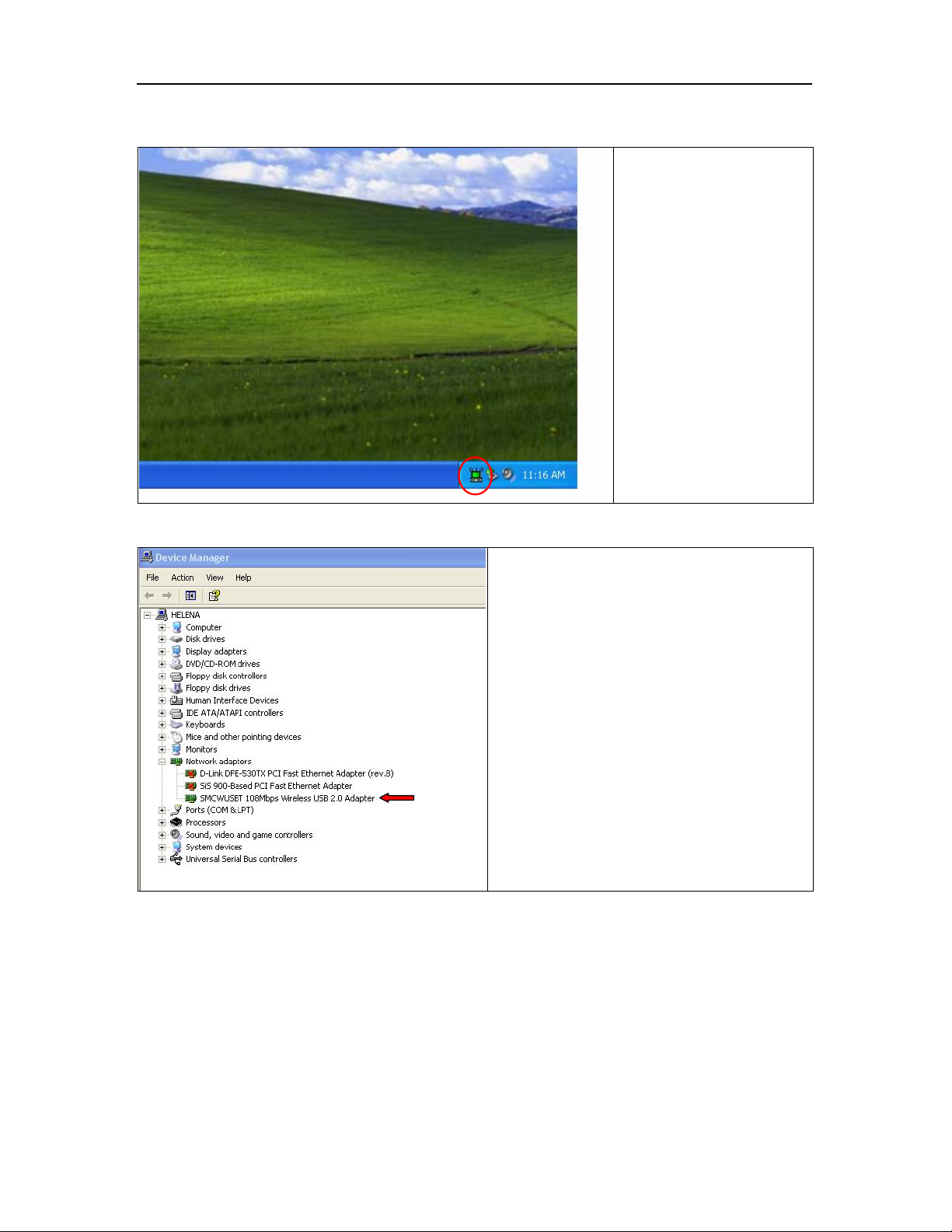
16.
When you succeed in
installing the driver, you will
see a logo indicating the
wireless signal strength at a
lower right corner of the
toolbar on desktop, after you
restart your computer.
17
Alternatively, you may check if this adapter is
successfully installed through Device Manager of
your computer. If it is successful, you will see
SMCWUSBT 108Mbps Wireless USB 2.0
Adapter under Network adapters of Device
Manager.
10
Page 18
Chapter 3: Utility Configuration
Chapter 3 Utility Configuration
The configuration of the Wireless LAN Card is done through the USB Wireless LAN Configuration Utility.
The utility also includes a number of tools to display current statistics and status infor mation pert aining to
your Wireless LAN Card.
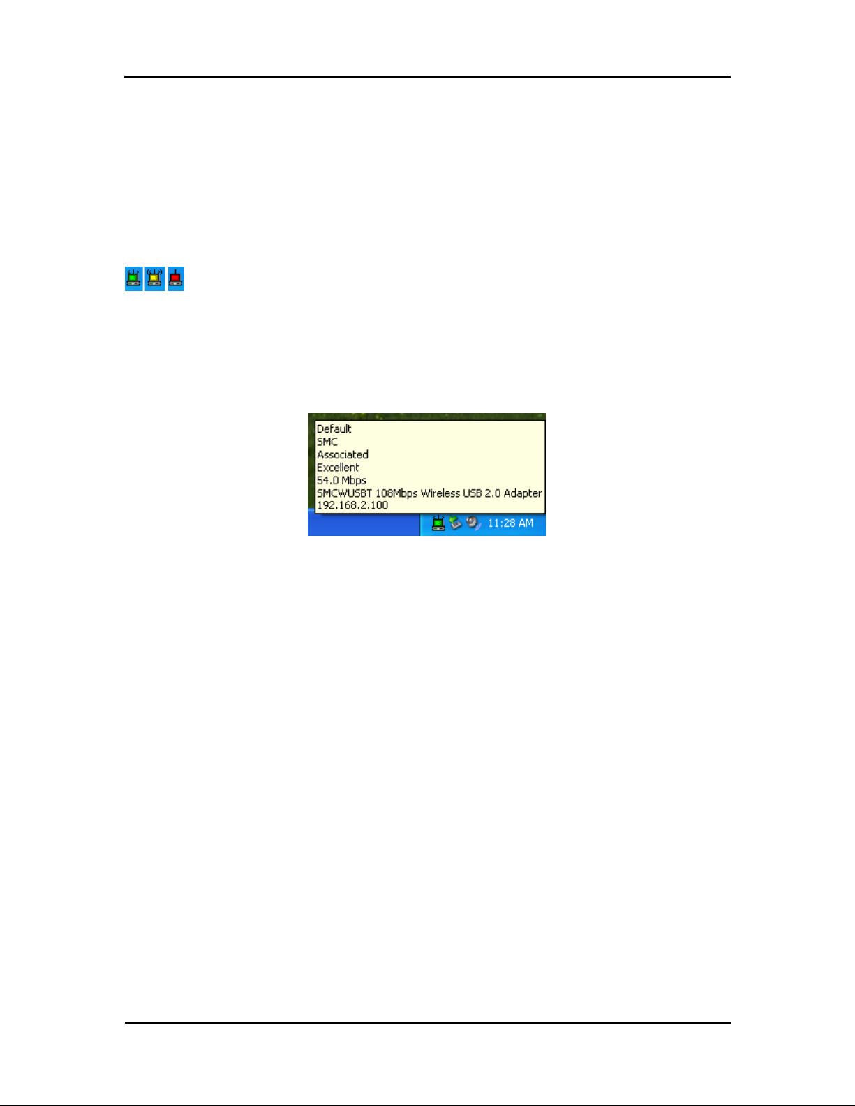
Tray Icon
The tray icon appears at the bottom of the screen.
Hold the mouse cursor over the tray icon to display the current configuration profile name and
association, as well as transmit and receive speed and the wireless adapter name.
11
Page 19

Wireless USB 2.0 Adapter
Right clicking on the tray icon , you can see a menu on which configuration items of the utility
appears.
Each item under the menu is defined below.
Help
Open the online help.
Exit Exit the utility application.
Open SMCWUSB
108Mbps Wireless USB
2.0 Adapter Utility …
Preferences Set the Startup Options and Menu Options for the utility.
Enable/Disable Radio
Manual LEAP Login
Reauthenticate
Select Profile
Show Connection Status
Launch the utility. Use the utility to configure the profile or
view status and statistics information.
Check whether the program should start automatically when
Windows starts, and check the menu items that should
appear on the popup menu.
Enable or disable the RF Signal.
Log in to LEAP manually, if LEAP is set to manually prompt
for user name and password on each login.
Re-authenticate to the access point.
Click a configuration profile name to switch to it. If no
configuration profile exists for a connection, add
first.
a profile
Display the Connection Status window. This window
displays information about the connection:
Active Profile
Auto Profile
Selection
Connection Status
Displays the name of the active
configuration profile.
Shows whether au t o profile selection
is enabled.
Displays whether the adapter is
connected to a wireless network.
Link Qualit y Lists the quality of the link connection.
SSID
Access Point
Name
Access Point IP
Address
Displays the SSID of the associated
network.
Shows the name of the access point
the wireless adapter is connected to.
Shows the IP address of the access
point the wireless adapter is
connected to.
Link Speed Lists the speed of the link connection.
Client Adapter IP
Address
Displays the IP address of the
wireless adapter.
Checking the Connection Status
12
Page 20

Chapter 3: Utility Configuration
You may double click the wireless tray icon at the lower right corner of your PC monitor. Then, a
small status screen appears as follows.
Accessing Vendor’s Wireless LAN Utility
Please right click the wireless tray icon at the lower right corner and select Open SMCWUSBT
108Mbps Wireless USB 2.0 Adapter Utility… as illustrated below.
If the wireless tray icon is not launched, you can manually start
the Wireless LAN Utility by selecting St art > Programs >
Note
SMCWUSBT 108Mbps Wireless USB 2.0 Adapter >
SMCWUSBT 108Mbps Wireless USB 2.0 Adapter Client
Utility.
13
Page 21
Wireless USB 2.0 Adapter
Configuration Tab
Go to the configuration tab on the user interface to set parameters for this adapter.
After opening the option of SMCWUSBT 108Mbps Wireless USB 2.0 Adapter Utility…, you will see a
user interface as set below.
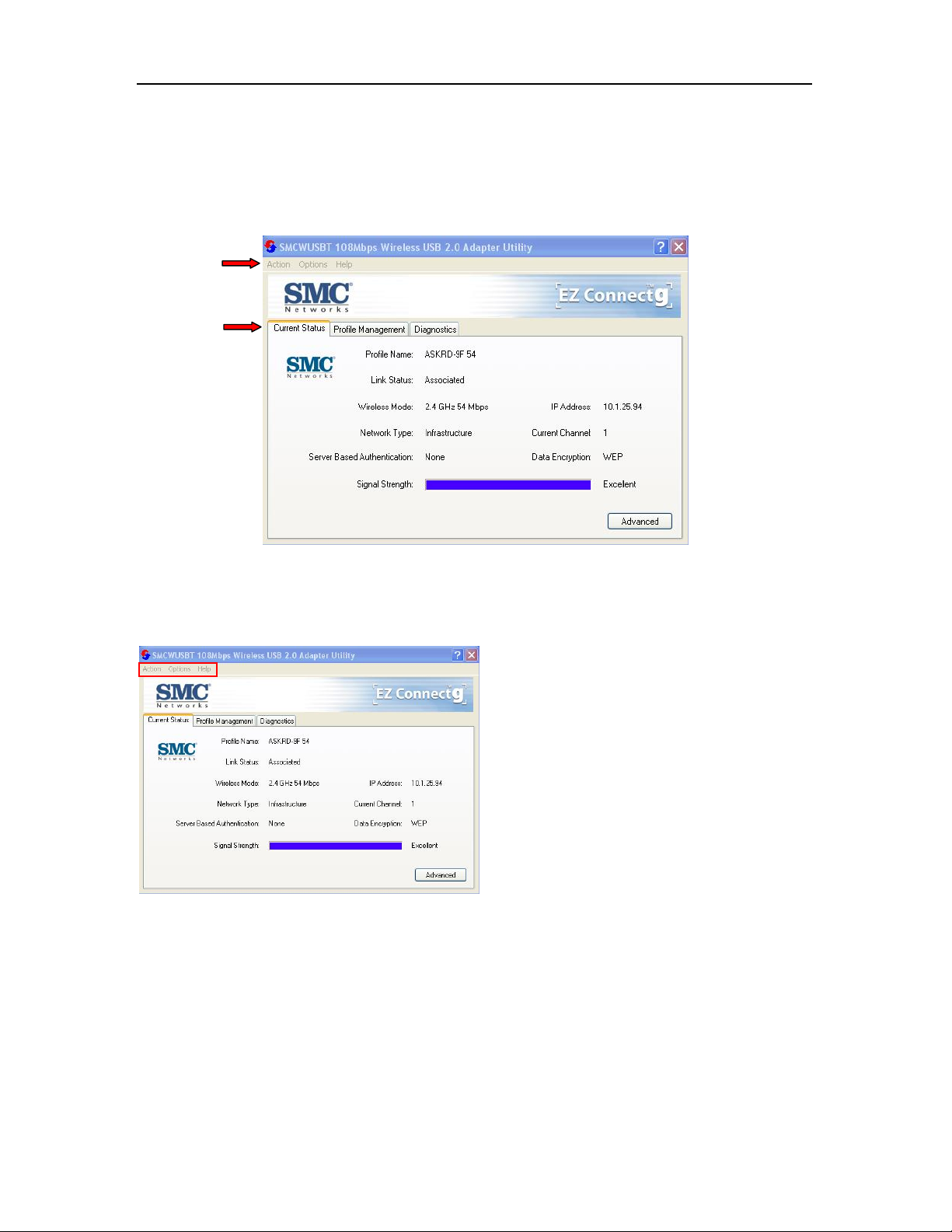
At the upper left side of the user interface, you can see 3 items as utility tools, Action, Options, and
Help. Next, you can also see 3 main items you should know, Current Status, Profile Management, and
Diagnostics. Please read the following descriptions and you can know how to read the connection
status and use the tool.
You can use the tools of utility that are framed in
red. The tools are Action, Options, and Help.
14
Page 22

Action Tab
Use the Action menu to access the Utility tools:
Chapter 3: Utility Configuration
1. Enable/Disable Radio: Enable or disable the
RF Signal on all Atheros station reference
designs.
2. Enable/Disable Tray Icon: Enable or disable
the tray icon
3. Manual LEAP Login: Lo g in to L EAP m anually,
if LEAP is set to manually prompt for user name
and password on each login.
4. Reauthenticate: Re-authenticate to a
LEAP-configured access point.
5. Exit: Exit the Utility app lication.
.
Options Tab
To change the display settings, choose Options > Display Settings from the menu.
Display Settings:
1. Signal Strength Display Units: Set the units
used when displaying signal strength:
percentage (%) or dBm.
2. Refresh Interval: Use the up/down arrows to
set the display refresh interval in seconds.
3. Data Display: Set the display to cumulative or
relative:
Relative: displays the change in
statistical data since the last update.
Cumulative: displays statistical data
collected since opening the profile.
15
Page 23

Wireless USB 2.0 Adapter
Help Tab
If you want to know the operation guide and the version number of utility, you can select Help for the
details, as shown below.
Current Status Tab
The Current Status tab contains general information about the program and its operations. The Current
Status tab does not require any configuration.
16
Page 24

Chapter 3: Utility Configuration
The following table describes the items found on the Current Status screen.
Profile Name
Link Status
Wireless Mode
IP Address
Network Ty pe
Current Channel
Server Based
Authentication
Data Encryption
Signal Strength
The name of the current selected conf iguration profile. Set up the
configuration name by clicking New or Modify on the Profile
Management tab.
Shows whether the station is associated to the wireless network.
Displays the wireless mode. See advanced information about the
program and its operations on the Advanced tab.
Displays the computer's IP address.
The type of network the station is connected to. The options include:
• Infrastructure (access point)
• Ad Hoc
Configure the network type on the Advanced tab.
Shows the currently connected channel.
Shows whether server-based authentication is used.
Displays the encryption type the driver is using. Configure the
encryption type by clicking New or Modify on the Profile
Management tab on the Security tab.
Shows the strength of the signal.
Advanced Tab
Click the Advanced button on the Current Status tab of the Utility to see advanced information about
the program and its operations. The Current Status tab does not require any configuration.
power in the figures are for illustration purpose only and does not represent the true number.)
)
(The available
17
Page 25

Wireless USB 2.0 Adapter
The following table describes the items found on the Advanced Status screen.
Network Name (SSID)
Displays the wireless network name.
Configure the network name by clicking New or Modify on the
Profile Management tab.
Server Based
Authentication
Data Encryption
Shows whether server-based authentication is used.
Displays the encryption type the driver is using. Configure the
encryption type by clicking New or Modify on the Profile
Management tab on the Security tab.
Authentication T ype
Displays the authentication mode.
Configure the authentication mode by clicking New or Modify on
the Profile Management tab.
Message Int eg rity
Check
Associated AP Name
Associated AP IP
Address
Associated AP MAC
Address
Power Save Mode
Shows whether MIC is enabled. MIC prevents bit-flip attacks on
encrypted packets.
Displays the name of the access point the wireless adapter is
associated to.
Shows the IP address of the access point the wireless adapter is
associated to.
Displays the MAC address of the access point the wireless adapter
is associated to.
Shows the power save mode. Power management is disabled in
ad hoc mode.
Configure the power save mode on the Advanced tab by clicking
Modify.
Current Power Level
Displays the transmit power level rate in mW.
Configure the transmit power level on the Advanced tab by
clicking Modify.
Available Power
Levels
Current Signal
Strength
Shows the 802.11a and/or 802.11b/g available power levels.
Shows the current signal strength in dBm.
Current Noise Level Displays the current noise level in dBm.
Up Time
Shows how long the client adapter has been receiving power (in
hours:minutes:seconds). If the adapter runs for more than 24
hours, the display shows in days:hours:minutes:seconds.
802.11b Preamble
Displays the 802.11b preamble format.
Configure the preamble format on the Advanced tab by clicking
Modify.
Current Receive Rate
Current Transmit Rate
Channel
Frequency
Channel Set
Shows the current receive rate in Mbps.
Displays the current transmit rate in Mbps.
Shows the currently connected channel.
Displays frequency the station is using.
Shows the current channel set.
18
Page 26
Chapter 3: Utility Configuration
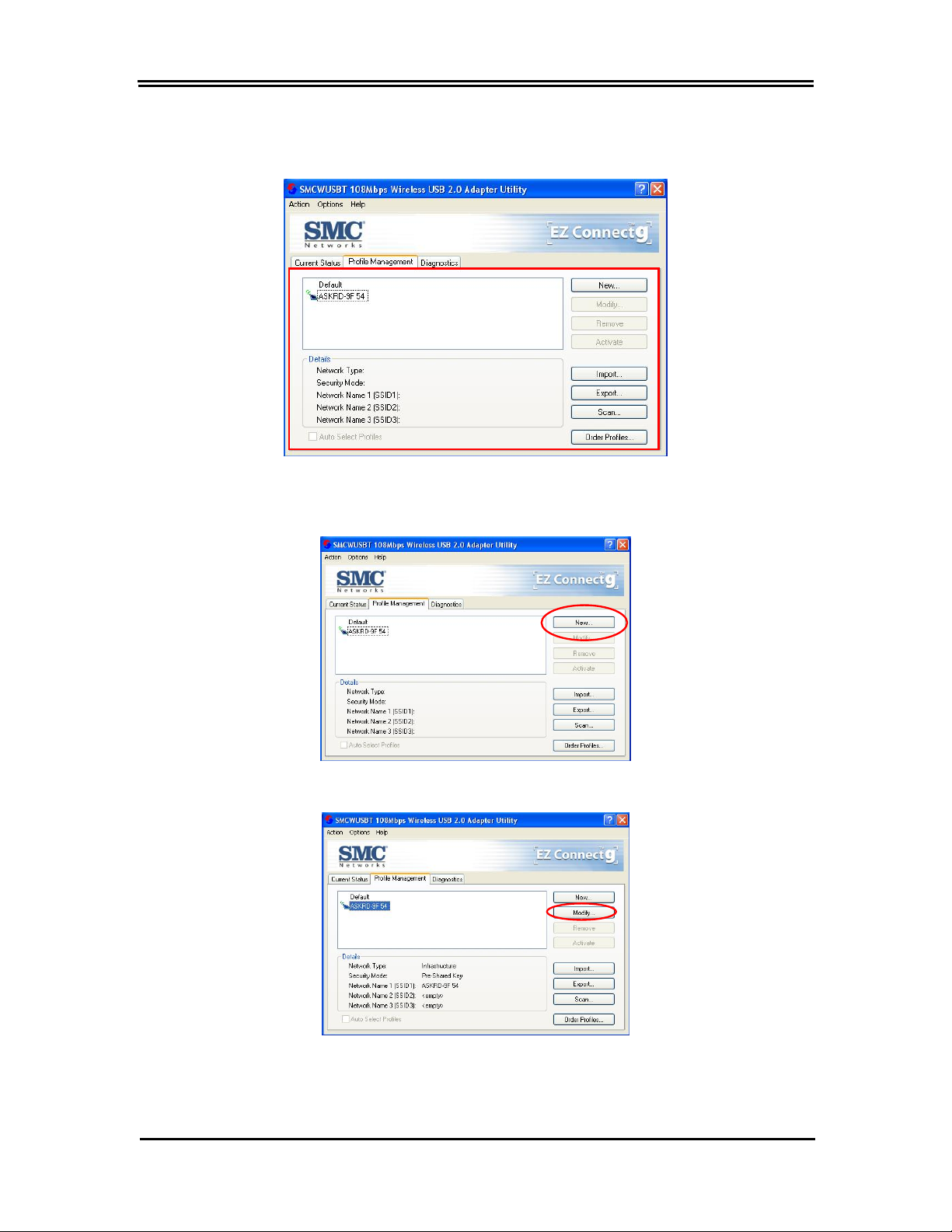
Profile Management
Configure the wireless network adapter (wireless card) from the Profile Management tab of the Utility.
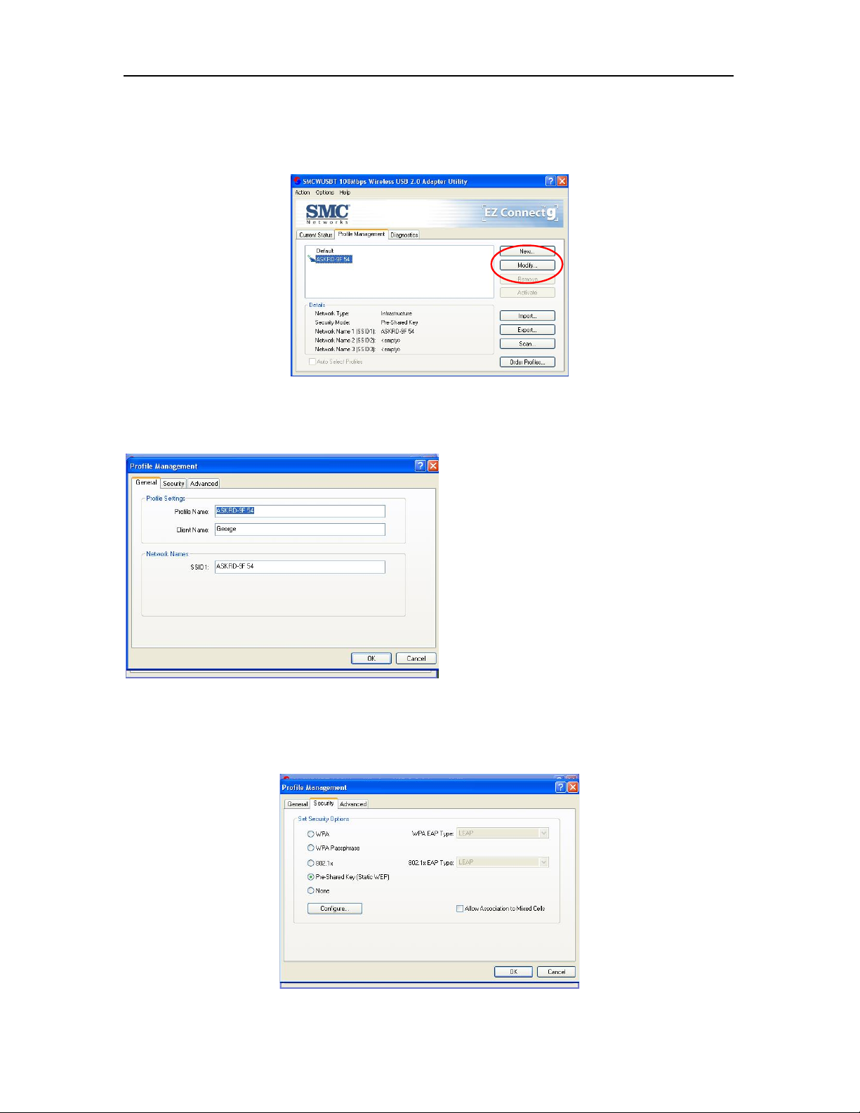
Creating or Modifying a Configuration Profile
To add a new configuration profile, click New on the Profile Management tab
To modify a configuration profile, select the configuration from the Profile list and click the Modify button.
19
Page 27
Wireless USB 2.0 Adapter
General Tab
In the Utility, access the General tab by clicking New or Modify on the Profile Management tab.
Edit the fields in the General tab to configure the configuration profile. Make sure to also edit the
Security and Advanced tabs.
1. Profile Name: Identifies the configuration
profile. This name must be unique. Profile
names are not case sensitive.
2. Client Name: Identifies the client machine.
3. Network Names (SSIDs): The IEEE 802.11
wireless network name. This field has a
maximum limit of 32 characters. Configure up
to three SSIDs (SSID1, SSID2, and SSID3).
Security Tab
In the Utility, access the Security tab by clicking New or Modify on the Profile Management tab. Click
the Security tab in the Profile Management window.
20
Page 28

Chapter 3: Utility Configuration
Edit the fields in the Security tab of Profile Management to configure the profile. To define the security
mode, select the radio button of the desired security mode. Make sure to also edit the General and
Advanced tabs.
Passphrase
WPA Enables the use of Wi-Fi Protected Access (WPA).
Choosing WPA opens the WPA EAP drop-down menu. The options
WPA
802.1x
include:
Enables WPA Passphrase security.
Click on the Configure button and fill in the WPA Passphrase.
Enables 802.1x security. This option requires IT administration.
Choosing 802.1x opens the 802.1x EAP type drop-down menu. The
options include:
• EAP-TLS
• EAP-TTLS
• PEAP (EAP-GTC)
• PEAP (EAP-MSCHAP V2)
• LEAP
Pre-Shared Key
(Static WEP)
None
• EAP-TLS
• EAP-TTLS
• PEAP (EAP-GTC)
• PEAP (EAP-MSCHAP V2)
• LEAP
If the access point that the wireless adapter is associating to has WEP
set to Optional and the client has WEP ena bled, mak e sure that Allow
Association to Mixed Cells is checked on the Security Tab to allow
association.
Enables the use of pre-shared keys that are defined on both the access
point and the station.
To define pre-shared encryption keys, choose the Pre-Shared Key radio
button and click the Configure button to fill in the Define Pre-Shared
Keys window.
If the access point that the wireless adapter is associating to has WEP
set to Optional and the client has WEP ena bled, mak e sure that Allow
Association to Mixed Cells is checked on the Security Tab to allow
association.
No security (not recommended).
21
Page 29
Wireless USB 2.0 Adapter
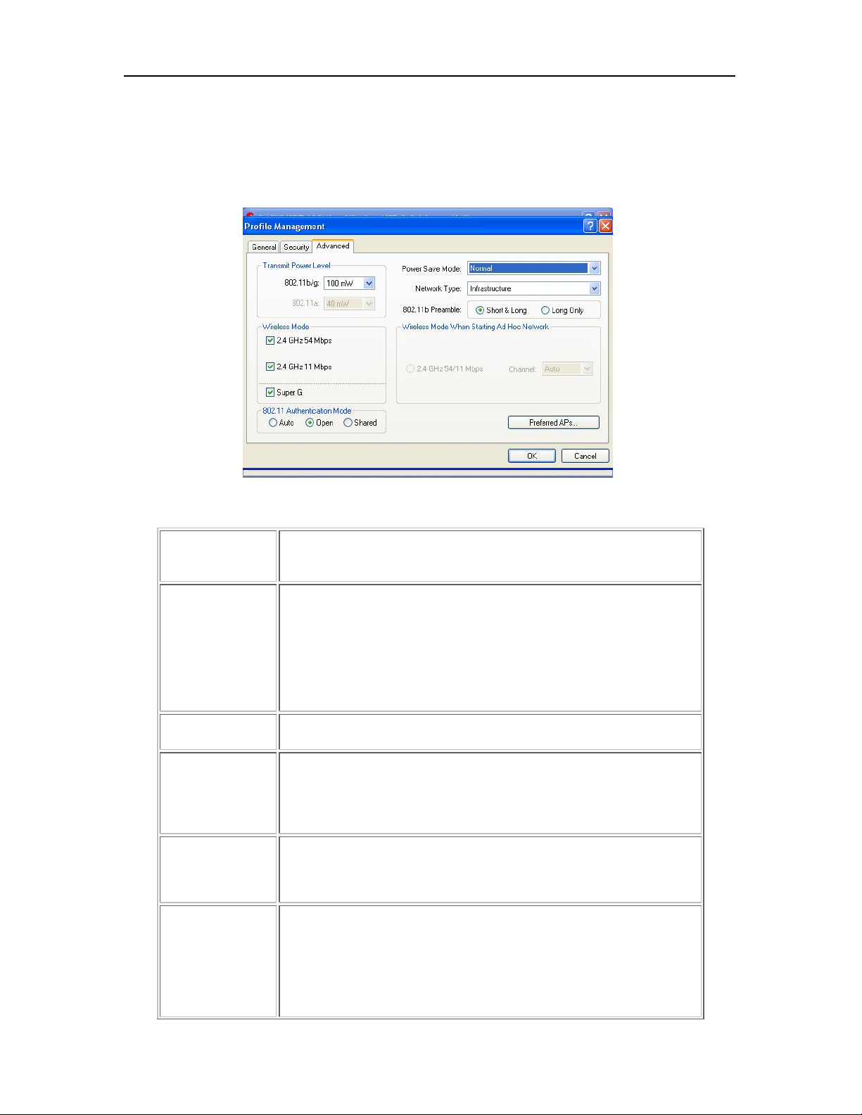
Advanced Tab
In the Utility, access the Advanced tab by clicking New or Modify on the Profile Management tab, then
clicking the Advanced tab in Profile Management.
Edit the fields in the Advanced tab of Profile Management to configure the profile. Make sure to also
edit the General and Security tabs.
Transmit Power
Selects the transmit power level for 80211b/g or 802.11a in mW. Actual
Level
transmit power may be limited by regulatory domain or hardware
limitations.
Power Save
Specify:
Mode
Maximum mode causes the access point to buffer incoming messages
for the wireless adapter. The adapter up periodically polls the access
point to see if any messages are waiting.
Normal uses maximum when retrieving a large number of packets, then
switches back to power save mode after retrieving the packets.
Off turns power saving off, thus powering up the wireless adapter
continuously for a short message response time.
Network Type
Specifies the network as either infrastructure (access point mode) or ad
hoc.
802.11b Preamble Specifies the preamble setting in 802.11b. The default setting is Short
& Long (access point mode), which allows both short and long headers
in the 802.11b frames. The adapter can only use short radio headers if
the access point supports and uses them. Set to Long Only to override
allowing short frames.
Wireless Mode
Specifies 5GHz 54 Mbps, 2. 4 GHz 54 Mbps, 2.4 GHz 11 Mbps, or
Super A/G operation in an access point network.
The wireless adapter must match the wireless mode of the access point
it associates to.
Wireless Mode
when Starting an
Ad Hoc Network
Specifies 5GHz 54 Mbps, 5GHz 108 Mbps, or 2.4 GHz 54/11 Mbps to
start an ad hoc network if no matching network name is found after
scanning all available modes.
This mode also allows selection of the channel the wireless adapter
uses. The channels available depend on the regulatory domain. If the
adapter finds no other ad hoc adapters, this selection specifies which
channel with the adapter starts the ad hoc network with.
22
Page 30

Chapter 3: Utility Configuration
The wireless adapter must match the wireless mode and channel of the
clients it associates to.
802.11a
Authentication
Select what mode the wireless adapter uses to authenticate to an
access point:
Mode
Auto causes the adapter to attempt authentication using Shared, but
switches it to open authentication if Shared fails.
Open enables an adapter to attempt authentication regardless of its
WEP settings. It will only associate with the access point if the WEP
keys on both the adapter and the acce ss point match.
Shared only allows the adapter to associate with access points that
have the same WEP key.
The Utility only allows the creation of 16 configuration profiles. After the
creation of 16 profiles, clicking the New button displays an error
Note
message. Remove an old profile or modify an existing profile for a new
use.
Infrastructure (Access Point) Mode
In infrastructure (access point (AP)) mode, the wireless network adapter participates in a basic
service set (BSS) as a station, and communicates with the other stations through an AP, as
illustrated here.
23
Page 31
Wireless USB 2.0 Adapter
Infrastructure (Access Point) Mode Profile Configuration
To configure a profile in infrastructure (access point) mode, change the Network Type in the Advanced
tab. For access point mode, modify the settings:
Transmit Power Level
Power Save Mode
802.11b Preamble (if using 802.11b)
Wireless Mode
802.11a Authentication Mode (if using 802.11a)
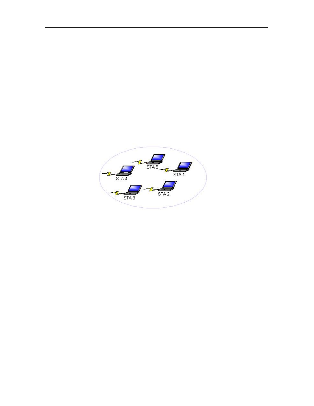
Ad Hoc Mode
In ad hoc mode, a wireless network adapter works within an independent basic service set
(IBSS), as illustrated here. All stations communicate directly with other stations without using
an access point (AP)
.
Ad Hoc Mode Profile Configuration
To configure a profile in ad hoc mode, change the Ne twor k Type in the Profile Management's
Advanced tab. For ad hoc mode, modify the settings:
Network Name (on General Tab)
Transmit Power Level
802.11b Preamble (if using 802.11b)
Wireless Mode When Starting an Ad Hoc Network
24
Page 32
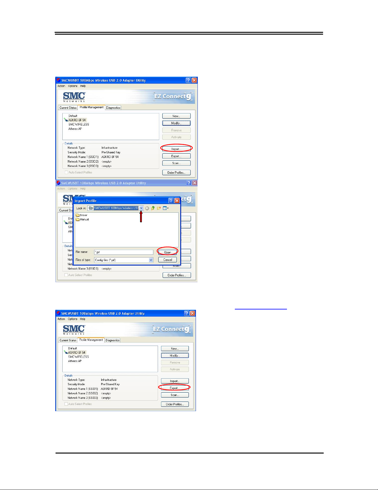
Import and Export Profiles
Importing a Profile
Chapter 3: Utility Configuration
1. From the Profile Management tab, click
the Import button. The Import Profile
window appears.
2. Browse to the directory where the profile is
located.
3. Highlight the profile name.
Exporting a Profile
4. Click Open. The imported profile appears
in the profiles list.
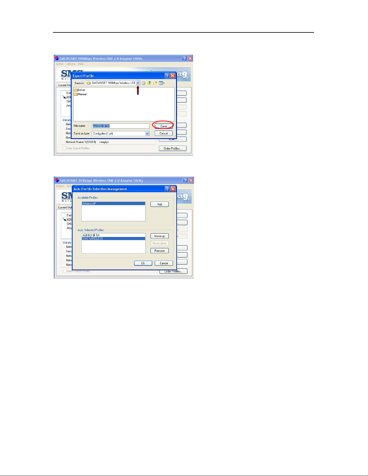
1. From the Profile Management tab, highlight the
profile to ex port. Click the Export button. The
Export Profile window appears.
25
Page 33
Wireless USB 2.0 Adapter
Order Profiles
2. Browse to the directory to export the profile
to.
3. Click Save. The profile is exported to the
specified location.
1. Highlight a profile in the Auto Selected
Profiles box.
2. Click Move Up or Move Down as appropriate.
The first profile in the Auto Selected Profiles
box has highest priority, and the last profile has
lowest priority.
3. Click OK.
4. Check the Auto Select Profiles box.
5. Save the modified configuration file.
When auto profile selection is enabled by checking
Auto Select Profiles on the Profile Management
tab, the client adapter scans for an available
network. The profile with the highest priority and
the same SSID as one of the found networks is the
one that is used to connect to the network. If the
connection fails, the client adapter tries the next
highest priority profile that matches the SSID, and
so on.
With auto profile selection enabled, the wireless adapter scans for available networks. The
highest priority profile with the same SSID as a found network is used to connect to the
network. On a failed connection, the client adapter tries with the next highest priority profile.
26
Page 34

Chapter 3: Utility Configuration
Scan Available Networks
Click the Scan button on the Profile Management tab to scan for available infrastructure and
ad hoc networks. On this list, click Refresh to refresh the list at any time.
Connecting to a different network
Highlight a network name and click the Activate button to connect an available network. If no
configuration profile exists for that network, the Profile Management window opens to the
General tab. Fill in the profile name and click OK to
create the configuration profile for that
network.
Remove a Configuration Profile
1. Go to the Profile Management tab.
2. Select the profile to remove from the list of
configuration profiles.
3. Click the Remove button.
27
Page 35
Wireless USB 2.0 Adapter
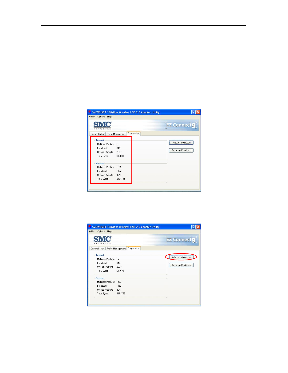
Diagnostics Tab
The Diagnostics tab of the Utility provides buttons used to retrieve receive and transmit statistics. The
Diagnostics tab does not require any configuration.
The Diagnostics tab lists the following receive and transmit diagnostics for frames received by or
transmitted by the wireless network adapter:
Multicast frames transmitted and received
Broadcast frames transmitted and received
Unicast frames transmitted and received
Total bytes transmitted and received
Adapter Information Button
Click the Adapter Information button for more general information about the wireless network adapter
and the network driver interface specification (NDIS) driver.
28
Page 36

Chapter 3: Utility Configuration
The Adapter Information button contains general information about the network interface card (the
wireless network adapter) and the n etwork driver interfac e specification (NDIS) driver. Access the
adapter information from the Diagnostics tab.
Card Name: The name of the wireless network
adapter.
MAC Address: The MAC address of the wireless
network adapter.
Driver: The driver name and path of the wireless
network adapter driver.
Driver Version: The version of the wireless
network adapter driver.
Driver Date: The creation date of the wireless
network adapter driver.
Client Name: The name of the client computer.
Advanced S tatistics
Click the Advanced Statistics button on the Diagnostics tab to also show receive and transmit
statistical information for the following receive and transmit diagnostics for frames received by or
transmitted to the wireless network adapter:
29
Page 37

Wireless USB 2.0 Adapter
Appendix A Regulatory Compliance
FCC Part 15 Declaration of Conformity (DoC)
The following equipment:
TM
Product name: EZ Connect
is herewith confirmed to comply with the requirements of FCC part 15 rules. The operation is
subject to the following two conditions:
(1) This device may not cause harmful interference, and
(2) this device must accept any interference received, including interference that may cause
undesired operation.
g 802.11g 108Mbps Wireless USB2.0 Adapter
SMC declares that SMCWUSBT-G (FCC ID: H8NWLU3010
2.4GHz by specified firmware controlled in U.S.A.
D11) is limited in Ch1~Ch11 for
FCC Rules and Regulations – Part 15
Warning: This equipment has been tested and found to comply with the limits for a Class B
digital device, pursuant to Part 15 of the FCC Rules. These limits are designed to provide
reasonable protection against harmful interference in a residential installation. This
equipment generates, uses and can radiate radio frequency energy and, if not installed and used
in accordance with the instructions, may cause harmful interference to radio communications.
However, there is no guarantee that interference will not occur in a p articular installation. If
this equipment does cause harmful interference to radio or television reception, which can be
determined by turning the equipment off and on, the user is encouraged to try to correct the
interference by one of the following measures:
30
z Reorient or relocate the receiving antenna.
z Increase the separation between th e equipment and receiver.
z Connect the equipment into an outlet on a circuit different from that
to which the receiver is connected.
z Consult the dealer or an experienced radio/TV technician for help.
Page 38

Chapter 3: Utility Configuration
IMPORTANT NOTE:
FCC Radiation Exposure Statement:
This equipment complies with FCC radiation exposure limits set forth for an uncontrolled environment.
End users must follow the specific operating instructions for satisfying RF exposure compliance.
The highest SAR value for the device when tested for use is 0.757 W/kg (for DSSS) and 0.316 W/kg
(for OFDM)
This transmitter must not be co-located or operating in conjunction with any other
antenna or transmitter.
FCC Caution: Any changes or modifications not expressly approved by the party responsible
for compliance could void the user's authority to operate this equipment.
Canada-Industry Canada (IC)
Operation is subject to the following two conditions:
1) this device may not cause interference and
2) this device must accept any interference, including interference that may cause
undesired operation of the device.
This device has been designed to operate with an antenna having a maximum gain of 2
dBi.
Antenna having a higher gain is strictly prohibited per regulations of Industry Canada.
The required antenna impedance is 50 ohms.
31
Page 39

Wireless USB 2.0 Adapter
Appendix B EC Declaration of Confirmity
EC Declaration of Conformity
This device complies with the essential requirements of the R&TTE Directive 1999/5/EC. The following
references have been applied in order to prove presumption of compliance with the R&TTE Directive
1999/5/EC:
- EN 60950
Safety of Information Technology Equipment.
- Council recommendation 1999/519/EC of 12 July 1999, limitations of exposure of the general public
to electromagnetic fields (0 Hz to 300 GHz).
- EN 300 328-1
Technical requirements for 2.4 GHz radio equipment.
- EN 301 489-1
EMC requirements for radio equipment.
English Hereby, SMC Networks, declares that this Radio LAN device is in compliance
Dutch Hierbij verklaart SMC Networks dat het toestel Radio LAN device in
French Par la présente SMC Networks déclare que l'appareil Radio LAN device est
German Hiermit erklärt SMC Networks, dass sich dieses Wireless LAN Gerät in
Spanish Por medio de la presente SMC Networks declara que el Radio LAN device
, EN 301 489-17
with the essential requirements and other relevant provisions of Directive
1999/5/EC. The official EC-Declaration of Conformity can be found under the
corresponding product section on the w e b http://www.smc.com
overeenstemming is met de essentiële eisen en de andere relevante bepalingen
van richtlijn 1999/5/EG. Het officiële EC- gelijkvormigheidattest kan men vinden
op de internetsite http://www.smc.com
conforme aux exigences essentielles et aux autres dispositions pertinentes de la
directive 1999/5/CE. La déclaration de conformité officielle peut être trouvée
sur notre site internet http://www.smc.com
Übereinstimmung mit den grundlegenden Anforderungen und den anderen
relevanten Vorschriften der Richtlinie 1999/5/EG befindet. Die offizielle
EC-Declaration of Conformity finden Sie im Internet unter http://www.smc.com
unter der entsprechenden Produktkategorie.
cumple con los requisitos esenciales y cualesquiera otras disposiciones
aplicables o exigibles de la Direct iva 1999/5/CE. The official EC-Declaration of
Conformity can be found under the corresponding product section on the web
http://www.smc.com
.
onder de betrokken productcategorie.
dans la rubrique Produits.
.
32
Page 40

Chapter 3: Utility Configuration
Countries of Operation & Conditions of Use in EC/ EFTA member states
English This device is a 2.4 GHz wireless LAN transceiver, intended for indoor ho me and
office use in all notified EC and EFTA member states. In accordance with article
6.4 of the R&TTE Directive 1999/5/EC the following EC/ EFTA member states
have been notified:
Austria, Belgium, Denmark, Finland, France, Germany, Italy, Luxembourg,
Netherlands, Norway, Spain, Sweden, Switzerland, United Kingdom, Portugal,
Greece, Ireland, Iceland
Requirements for outdoor operation, like license requirements and allowed
channels of operation apply in some countries. Please contact your local
regulation authority or SMC Networks for details on current restrictions for
outdoor use.
Dutch Dit toestel is een 2.4 Ghz draadloze Lan transceiver, bestemd voor gebruik
binnen huis en kantoor in alle geïnformeerde lidstaten van de EC en de EFTA.
In overeenstemming met artikel 6.4 van de R&T TE Directive 1999/5/EC zijn de
volgende EC/EFTA lidstaten verwittigd:
België, Denemarken, Duitsland, Finland, Frankrijk,Griekenland, Ierland, IJsland,
Italië, Luxemburg, Nederland, Noorwegen,Oostenrijk, Portugal, Spanje ,
Verenigd Koninkrijk, Zweden, Zwitserland.
Benodigdheden voor gebruik buiten, zoals gebruiksvergunningen en toegelaten
werkkanalen zijn van toepassing in sommige landen. Gelieve uw lokale instantie
of SMC Networks te contacteren voor details op huidige beperkingen voor
gebruik in buitenlucht.
French Ce produit est un appareil radio LAN transceiver de 2.4 GHz destiné aux PME et
à l’utilisation domestique dans tous les pays certifiés conformes aux conditions
de l’EU et de l’EFTA. En accord avec l’article 6.4 de la R&TTE directive
1999/5/EC, t he membres de la EU et de l’EFTA sont les suivants :
Autriche, Belgique, Danemark, finalnde, France, A llemagne, Italie, Luxembourg,
Pays-Bas, Norvège, Espagne, Suède, Suisse, Royaume-Uni, Portugal, Grèce,
Irelande, Icelande.
Des conditions sont appliquées à cert ains pays pour l’utilisation en extérieur, tels
que des licences spécífiques et des canaux d’opération. Veuillez contacter votre
autorité locale ou SMC Networks pour plus de détails quant aux restrictions
actuelles concernant l’utilisation en extérieur.
German Dieses Wireless LAN Gerät arbeitet im 2.4 GHz Frequenzband und ist für den
Einsatz im Innenbereich in den benachrichtigten EC/ EFTA Mitgliedstaaten
geeignet. In Übereinstimmung mit Artikel 6.4 der R&TTE Direktive 1999/5/EC
wurden folgende Mitgliedstaaten benachrichtigt:
Österreich, Belgien, Dänemark, Finland, Frankreich, Deutschland, Italien,
Luxemburg, Niederlande, Norwegen, Spanien, Schweden, Schweiz,
Großbritannien, Portugal, Griechenland, Irland, Island.
Für den Einsatz im Aussenbereich sind in einigen Ländern Lizenzen erforderlich
oder die Anzahl der Kanäle ist eingeschränkt. Bitte kontaktieren Sie Ihre
Regulierungsbehörde oder SMC Networks für die aktuellen Einschränkungen
beim Einsatz i m Aussenbereich.
Spanish Este aparato es un transmisor inalámbrico de 2.4 GHz, previsto para el uso
interior en domicilios y Pymes en todos los Estados de la CE y la EFTA
notificados . De acuerdo con el artí culo 6.4 de la Directiva R&TTE 1999/5/EC los
siguientes estados de la CE y de la EFTA han sido notificados:
Austria, Bélgica, Dinamarca, Finlandia, Francia, Alemania, Italia, Luxemburgo,
Países Bajos , Noruega, España, Suecia, Suiza, Reino Unido, Portugal, Grecia,
Irlanda, Islandia.
Los requisitos para su uso exterior, como requerimiento de licencia y canales de
operación permitidos se aplican en algunos países. Por favor contacte la
33
Page 41

Wireless USB 2.0 Adapter
autoridad reguladora local o SMC Networks para más detalles en relación con
las restricciones actuales para uso exterior.
SMC Contact for this device in Europe is:
SMC Networks Europe,
Edificio Conata II,
Calle Fructuos Gelabert 6-8, 2, 4ª,
08970 – Sant Joan Despi,
Barcelona, Spain
34
Page 42

FOR TECHNICAL SUPPORT, CALL:
From U.S.A. and Canada (24 hours a day, 7 days a week)
(800) SMC-4-YOU; Phn: (949) 679-8000; Fax: (949) 679-1481
From Europe : Contact details can be found on www.smc.com
INTERNET
E-mail address:
techsupport@smc.com
Driver updates:
http://www.smc.com/index.cfm?action=tech_support_drivers_downloads
World Wide Web:
http://www.smc.com
For Literature or Advertising Response, Call:
U.S.A. and Canada: (800) SMC-4-YOU Fax (949) 679-1481
Spain: 34-91-352-00-40 Fax 34-93-477-3774
UK: 44 (0) 1932 866553 Fax 44 (0) 118 974 8701
France: 33 (0) 41 38 32 32 Fax 33 (0) 41 38 01 58
Italy: 39 (0) 3355708602 Fax 39 02 739 14 17
Benelux: 31 33 455 72 88 Fax 31 33 455 73 30
Central Europe: 49 (0) 89 92861-0 Fax 49 (0) 89 92861-230
Nordic: 46 (0) 868 70700 Fax 46 (0) 887 62 62
Eastern Europe: 34 -93-477-4920 Fax 34 93 477 3774
Sub Saharan Africa: 216-712-36616 Fax 216-71751415
North West Africa: 34 93 477 4920 Fax 34 93 477 3774
CIS: 7 (095) 7893573 Fax 7 (095) 789 357
PRC: 86-10-6235-4958 Fax 86-10-6235-4962
Taiwan: 886-2-87978006 Fax 886-2-87976288
Asia Pacific: (65) 238 6556 Fax (65) 238 6466
Korea: 82-2-553-0860 Fax 82-2-553-7202
Japan: 81-45-224-2332 Fax 81-45-224-2331
Australia: 61-2-8875-7887 Fax 61-2-8875-7777
India: 91-22-8204437 Fax 91-22-8204443
If you are looking for further contact information, please visit www.smc.com
Model Number: SMCWUSBT-G
38 Tesla
Irvine, CA 92618
Phone: (949) 679-8000
 Loading...