

Page 1

Mini PCI Wireless LAN/Modem Card
User’s Manual
Page 2

Information in this document is subject to change without notice. No part of this document may be
reproduced or transmitted in any form or by any means, electronic or mechanical, for any purpose,
without the express written permission of the seller.
The seller provides this documentation without warranty, term, or condition of any kind. The seller
may make improvements or changes in the product(s) and/or the program(s) described in this
documentation at any time.
Other product and compa ny names here in may be tra demarks of their respective owners.
2002 All rights reserved.
Page 3

Contents
About This User’s Manual..........................................................................................................................................vii
Chapter 1 Introduction.................................................................................................................................................1
Wireless LAN Card Features.......................................................................................................................................1
Modem Card Features.................................................................................................................................................2
Wireless LAN Basics...................................................................................................................................................3
Local Area Network (LAN)....................................................................................................................................................... 3
Ad Hoc Network........................................................................................................................................................................ 4
Infrastructure Network ............................................................................................................................................................. 4
Roaming.................................................................................................................................................................................... 4
Chapter 2 Installing the Driver and Utility Software.................................................................................................5
System Requirements.................................................................................................................................................5
Installing Wireless LAN/Modem Driver and Software..................................................................................................6
Chapter 3 Configuring Wireless LAN Card Settings ................................................................................................ 9
PART 1. Using Prism Utility Program ......................................................................................................................... 9
I
Page 4

Mini PCI Wireless LAN / Modem Card User's Manua l
Wireless LAN Card Monitor Icon................................................................................................................................9
PRISM Wireless Settings Utility.................................................................................................................................11
Status.........................................................................................................................................................................12
Configuration .............................................................................................................................................................14
Encryption..................................................................................................................................................................18
About .........................................................................................................................................................................21
PART 2. Using Windows XP Configuration Utility..................................................................................................22
Connecting to an Access Point or W ireless LAN Card.............................................................................................. 23
Viewing Wireless Connection Status.........................................................................................................................25
Chapter 4 Country Selection for Mini PCI Modem Card.........................................................................................27
For Windows 98/Me...................................................................................................................................................27
For Windows 2000/XP...............................................................................................................................................27
Chapter 5 Removing Wireless LAN/Modem Card Software...................................................................................29
Removing Wireless LAN Card Software ...................................................................................................................29
For Windows 98/Me ............................................................................................................................................................... 29
For Windows 2000/XP............................................................................................................................................................ 30
Removing Mini PCI Modem Software ....................................................................................................................... 30
For Windows 98/Me ............................................................................................................................................................... 30
For Windows 2000/XP............................................................................................................................................................ 30
Chapter 6 Commands Reference .............................................................................................................................33
II
Page 5

Contents
6.1 Basic AT Command.............................................................................................................................................33
6.2 Result Codes.......................................................................................................................................................50
6.3 S-Registers..........................................................................................................................................................56
6.4 Fax Command.....................................................................................................................................................61
Chapter 7 Troubleshooting.......................................................................................................................................69
For Wireless LAN Card..............................................................................................................................................69
Radio Interference.................................................................................................................................................................. 69
Cannot Connect to Another Wireless LAN Card.................................................................................................................... 70
Poor Link Quality................................................................................................................................................................... 70
Cannot Connect to Access Point............................................................................................................................................. 71
For Modem Card .......................................................................................................................................................72
No Response From Your Modem............................................................................................................................................ 72
Your Modem Does Not Connect After It Has Dialed a Phone Number.................................................................................. 72
Can’t Transmit After Connecting to the Remote Modem........................................................................................................ 72
Appendix A Limited Warranty...................................................................................................................................73
Wireless LAN/Modem Card Hardware ......................................................................................................................73
Wireless LAN/Modem Software.................................................................................................................................74
Appendix B Regulatory Compliance........................................................................................................................75
FCC Part 15 Declaration of Conformity (DoC) ..........................................................................................................75
FCC Rules and Regulations - Part 15.......................................................................................................................76
FCC Radiation Exposure Statement .........................................................................................................................77
III
Page 6

Mini PCI Wireless LAN / Modem Card User's Manua l
Appendix C Setting Up TCP/IP..................................................................................................................................81
Appendix D Specification..........................................................................................................................................85
Mini PCI Wireless LAN Card .....................................................................................................................................85
Mini PCI Wireless LAN and Modem Card .................................................................................................................87
A. Wireless Specification........................................................................................................................................................ 87
B. Data/Fax Modem Specification.......................................................................................................................................... 88
Glossary.......................................................................................................................................................................91
IV
Page 7

Table of Figures
Figure 3-1 PRISM Wireless Settings Utility – Status Tab .................................................................................... 13
Figure 3-2 Peer-to-Peer Type Configuration........................................................................................................ 16
Figure 3-3 Access Point Type Configuration........................................................................................................ 17
Figure 3-4 PRISM Wireless Settings Utility – Encryption Tab.............................................................................. 20
Figure 3-5 PRISM Wireless Settings Utility – Version Tab ..................................................................................21
Figure 3-6 Windows XP – Connect to Wireless Network..................................................................................... 24
Figure 3-7 Windows XP – Connection Status...................................................................................................... 25
Contents
V
Page 8

Page 9

About This User’s Manual
This manual was written for two models:
•
Mini PCI Wireless LAN Card
•
Mini PCI Wireless LAN and 56K Modem Card
For brevity, throughout this manual Wireless LAN/Modem Card is used to indicate both
models. If your Mini PCI model does not come with Modem functionality, ignore the modemrelated descriptions in this manual. Also, the following terms/abbreviations are used
interchangeably:
•
Access Point-AP
•
Wireless LAN-WLAN
•
Ethernet net wor k - LAN - network
This User’s Manual contains information on how to install and configure your Mini PCI
Wireless LAN/Modem Card. From now on, we will guide you through the correct
configuration steps to get your device up and run.
vii
Page 10

Page 11

Chapter 1 Introduction
Depending on your Mini PCI
Card model, your device may
not come with Modem
functionality.
Wireless LAN Card Features
This Wireless LAN/Modem Card provides two types of connectivity on one miniscule card:
conventional modem connectivity and Wireless LAN connectivity. The card puts the IEEE
802.11b WLAN standard and V.92 Modem technology into one integrated circuit (IC) to work
in PCs, laptops and handheld devices. It effectively eliminates the need for add-in cards for the
end-users to remain connected to their corporate WLAN or the Internet.
On the WLAN side, the card uses 2.4 GHz Direct Sequence Spread Spectrum (DSSS)
technology, adaptively adjusting its data rate from 11 Mbps to 5.5/2.0/1.0 Mbps as the signal
strength warrants. Encryption at 64 or 128-bit levels is provided. Both Peer-to-Peer (Ad-Hoc)
and Access Pont (Infrastructure) mode are supported. In addition, its IEEE 802.11b standard
compliance ensures interoperability with other 802.11b compliant wireless LAN (WLAN)
products.
1
Page 12

Mini PCI Wireless LAN / Modem Card User's Manua l
Modem Card Features
On the Modem side, the FAX/Data modem gives your PC the ability to send and receive FAX
messages over the telephone line like a standard FAX machine. It also allows your PC to
communicate with other personal computers, terminals or BBS's (Bulletin Board Systems)
through the data modem functions.
The communication software, which should be used, depends on the kind of machine that you
are going to communicate with. If you are going to call a FAX machine then you must use the
Fax software. If the machine that you are going to communicate with is a modem then you
must use a data modem communications software.
Data mode capabilities
•
ITU-T V.92: 56000-28000 bits/s
•
ITU-T V.90: 56000-28000 bits/s
•
ITU-T V.34: 33600-2400 bits/s
•
V.44, V.42, V.42bis and MNP Class 5 data compression
•
V.32terbo, V.32bis and fallbacks
•
High compression throughput due to parallel access directly to the host PC.
FAX mode capabilities
•
ITU-T V.253 class 1 FAX
•
ITU-T V.34: 33600-2400 bits/s (TCM)
•
ITU-T V.17: 14400 bits/s, 12000 bits/s, 7200 bits/s (TCM)
2
Page 13

•
ITU-T V.29: 9600 bits/s, 7200 bits/s (QAM)
•
ITU-T V.27ter : 4800 bits/s, 2400 bits/s (DPSK)
•
ITU-T V.21 Channel 2:300 bits/s (FSK)
Wireless LAN Basics
This section conations some Wireless LAN basics to help you better understand how the
product works together to create a wireless network.
Local Area Network (LAN)
Simply put, a LAN is a network that exists in a relatively limited area. A network is two or
more computers connected together sharing files and peripheral devices such as printers.
The Wireless LAN Card allows you to interact with other computers without having to run
cables normally associated with networks. This lets you move your computer around while
staying connected to your network.
There are two ways to use the Wireless LAN Card. One way is to connect directly to one or
more Wirel ess LAN Card eq uipped computers, forming an Ad Hoc wireless network. The
second way is to connect to an Access Point that gives you access to an existing wired LAN,
forming an Infrastructure wireless network.
Chapter 1 Introduction
3
Page 14

Mini PCI Wireless LAN / Modem Card User's Manua l
Ad Hoc Network
The Ad Hoc network offers peer to peer connections between workstations, allowing
communication between computers within range that have an 802.11b DSSS compatible PC
card installed. A wireless Ad Hoc network can also access a wired LAN’s TCP/IP service
(such as e-mail and the Internet) by using a TCP/IP software router on an Ethernet equipped
PowerBook or notebook.
Infrastructure Network
The infrastructure network uses an access point (or several access points) as a gateway,
linking the wireless network to a wired LAN. As a result, portable workstations or desktops on
your wireless network have access to all of the fe atures of your wired LAN including e-mail,
Internet access, network printers and files server.
Roaming
Multiple Access Points can be installed to extend the wireless service coverage area for
seamless wireless access. Within an extended service area, all Access Points and wireless
clients must have the same Service Set Identity (SSID). Roaming among different Access
Points is controlled automatically to maintain the wireless connectivity at all times.
4
Page 15

Chapter 2 Installing the Driver and Utility Software
As the Wireless LAN/Modem Card is an embedded solution, your notebook is probably
shipped with its driver and software properly installed. If this is the case, ignore this chapter
and proceed with configuration steps in next chapter.
In case you need to install the driver and software for any reason, follow the instructions
described in this chapter.
System Requirements
To use the Wireless LAN/ Modem Card, your computer must meet the following mini mum
requirements:
Windows 98/Me/2000/XP
128MBytes of RAM, additional memory recommended
5
Page 16
Mini PCI Wireless LAN / Modem Card User's Manua l
Installing Wireless LAN/Modem Driver and Software
To allow the Wireless LAN/Modem Card to operate on your host computer, proper driver
installation is required. The provided Utility software is a Windows program that helps you
configure and monitor your Wireless LAN/Modem Card. For your convenience, driver
installation will be automatically processed while you install the utility software. Simply
proceed as follows:
If your operation system has not been installed with Wireless LAN/Mode m Card, the
Windows Plug-and-Play capability will automatically detect the new device(s) and display the
wizard requesting for drivers. If your model supports Modem function, both Wireless LAN
Card and Modem Card will be detected. Click Cancel to bypass the wizard screen(s) and then:
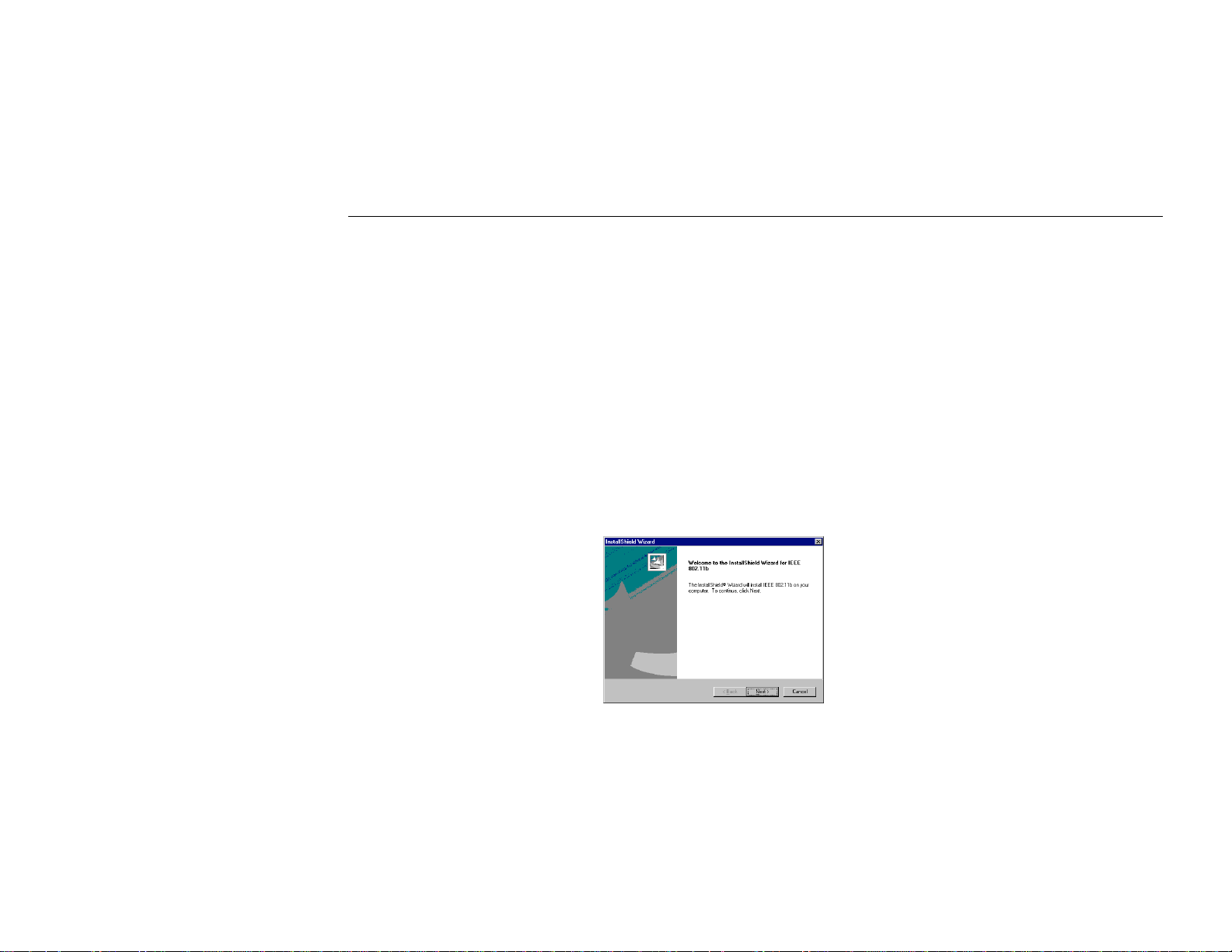
1. Insert the provided Software Utility CD into your CD-ROM drive. Locate and double-
click the file Setup.exe from the Software Utility CD. When the welcome screen pops up,
click Next.
6
Page 17

Chapter 2 - Installing the Wireless LAN Card
Depending on your operating syst em, following situation may occur:
•
For Windows 2000: If you are prompted with one or a couple of Digital Signature not
Found alarm messages, just click Yes to continue with the installation.
•
For Windows XP: When Found New Hardware Wizard appears, have Install the
software automatically selected and follow the on-screen instructions to proceed. If
compatibility message appears, just click Continue Anywa y.
2. Click Finish and follow system prompts to complete the installation.
Now you are done with the driver and software installation procedure. Select Start >
Programs > Askey > IEEE 802.11b. You should be able to see the PRISM Wireless
Settings utility icon appearing on the system tray. You may proceed to next chapter to
configure or fine-tune your Wireless LAN Card se ttings.
If you are going to configure countries for your Modem Card, refer to “Chapter 4 Country
Selection for Mini PCI Modem Card” on page 27.
Note: If you need to set up the TCP/IP properties for your Wireless LAN Card, refer to
“Appendix C Setting Up TCP/IP” on page 81 for details.
7
Page 18

Page 19

Chapter 3 Configuring Wireless LAN Card Settings
PART 1. Using Prism Utility Program
Wireless LAN Card Monitor Icon
If the utility is not launched,
manually start the monitor by
selecting Start > Programs
> Askey > IEEE 802.11b.
or double-clicking PRISM
Settings icon in the Control
Panel.
The Wireless LAN Card uses PRISM Wireless Settings
utility fo r both configuration and monitoring. Whenever
you start Windows, t
its
icon loaded on the system tray, located near the clock
on the task bar. Right-clicking the icon displays the
context menu as shown opposite:
he utility is launched automatically with
9
Page 20

Mini PCI Wireless LAN / Modem Card User's Manua l
Wireless Radio On/Off options allow you to send or stop sending radio signals. Stop send ing
radio signals will terminate your wireless connection. Clicking Remove Status Icon will
unload the icon from the system tray.
The color of the wireless icon changes to indicate your wireless connection quality. Possible
icon graphics and procedures to take are described in the table below:
Color Radio Connection Quality
Green Excellent or good connection
Yellow Marginal connection.
Red Poor connection or no r adio connection.
If “X” is placed over the icon, it may due to your WEP encryption
doesn’t match your target Access Point/Wireless Station and data frame
error occurs. Check your WEP settings.
The radio signal is weak. Move your de vice closer to your target Access
Point or Wireless Station.
No radio connection may due to you are out of range of the wireless
network or the SSID can not be found. Move your device closer to your
target Access Point/Wireless Station or verify your SSID settings.
If “X” is placed over the icon, radio signal is disabled.
10
Page 21
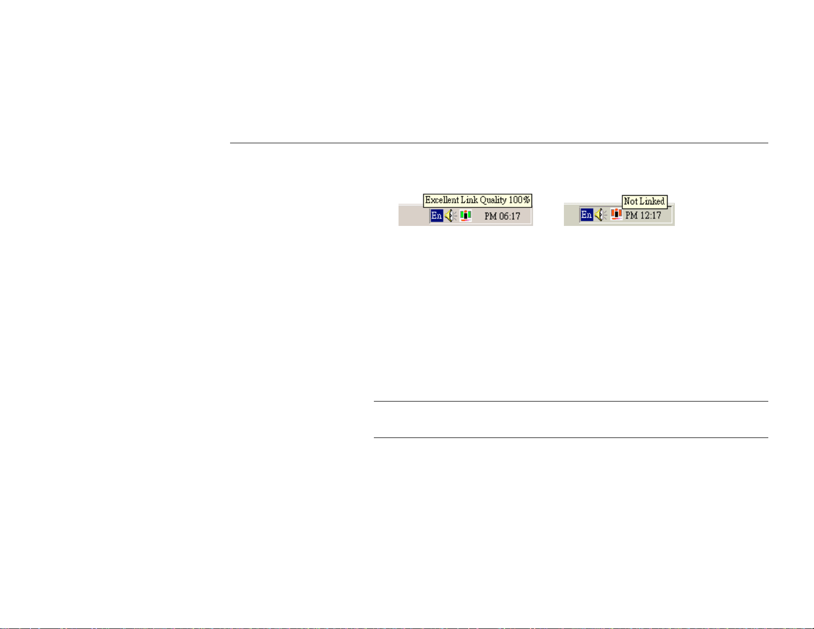
While connected, you can place your cursor over the icon to see the pop-up text that gives link
quality information about the current WLAN connection.
PRISM Wireless Settings Utility
You can access the PRISM Wireless Settings util ity by any of the following methods:
•
Double-click the utility icon on the system tray
•
Right-click the icon and select Wireless Network Status… (or any item in the same
group) from its context menu.
•
From the Windows Start menu, click Programs, ASKEY and then IEEE 802.11b.
The PRISM Wireless Settings utility screen pops up with four available tabs: Status,
Configuration, Encryption and About. Please see the appropriate section which describes
each tab item.
Note: For Windows XP users, your PRISM Wireless Settings utility may include only two
tabs. Refer to “PART 2. Using Windows XP Configuration Utilit y ” for more information on
restore the PRISM Wireless Settings utility.
Chapter 3 Configuring Wireless LAN Card Settings
11
Page 22

Mini PCI Wireless LAN / Modem Card User's Manua l
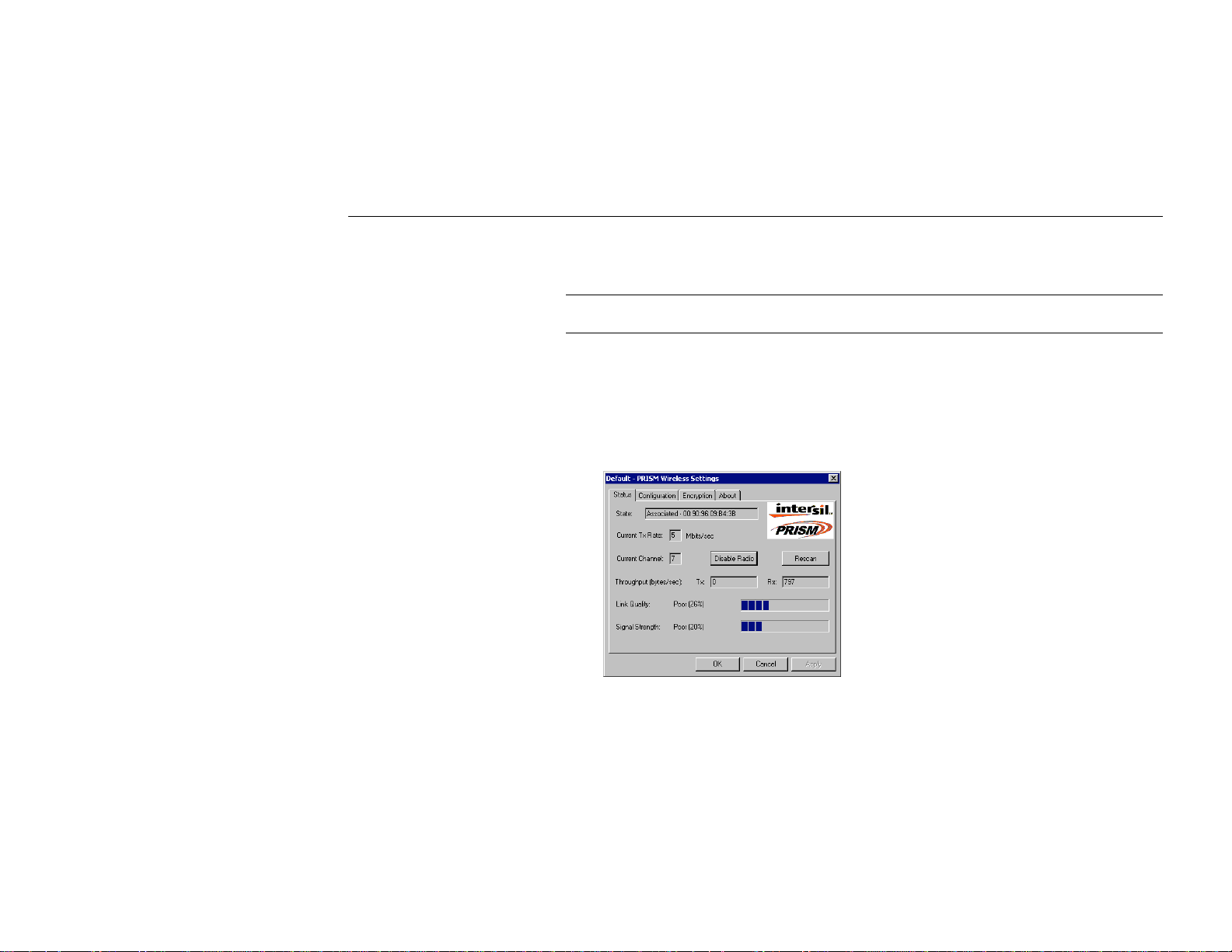
Status
Status functi on allows you to view the current status of your Wirel ess LAN Card.
State: Indicates current status of your WLAN card, such as scanning or authenticating. If your
WLAN card is connected to an Access Point or Wireless LAN Card, it displays the MAC
address of the Access Point /Wireless Station you are associated with.
Current Tx Rate: Indicates the transmit speed currently in use.
Current Channel: The channel currently in use.
Throughput (bytes/sec): Displays the instantaneous Tx and Rx throughput rate for each poll
period.
Link Quality: Use percentages and progress indicators to indicate your Wireless LAN Card’s
link quality. The Link Quality categories are defined as follows:
Link Quality Range (%)
Poor 0-29
Fair 30-59
Good 60-89
Excellent 90-100
12
Page 23
Chapter 3 Configuring Wireless LAN Card Settings
Signal Strength: Displayed as percentages using active progress indicators that change as the
network radio signal fluctuates.
Note: If you are in Peer-to-Peer mode, the Signal Strength and Link Quality fields are not
applicable. Both fields are dimmed.
Enable/Disable Radio: The button allows you to enable/disable radio operation. If you
disable the radio transmission, your WLAN card stops sending radio signals and you are
disconnected to the wireless network. In the mean time, the Status filed displays Radio Off.
Rescan: Allows you to immediately rescan the radio channel searching for available Access
Point/Wireless Station.
Figure 3-1 PRISM Wireless Settings Utility – Status Tab
13
Page 24

Mini PCI Wireless LAN / Modem Card User's Manua l
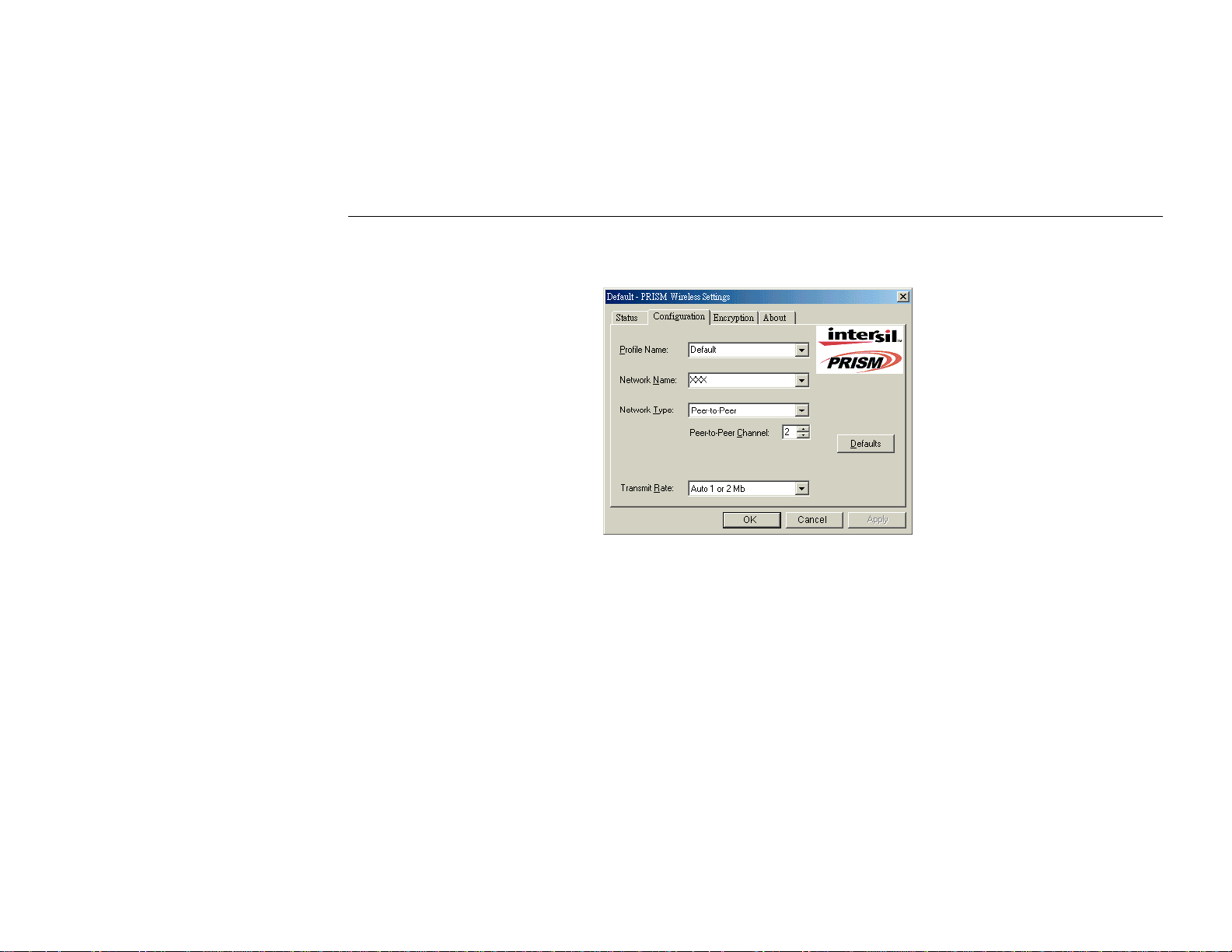
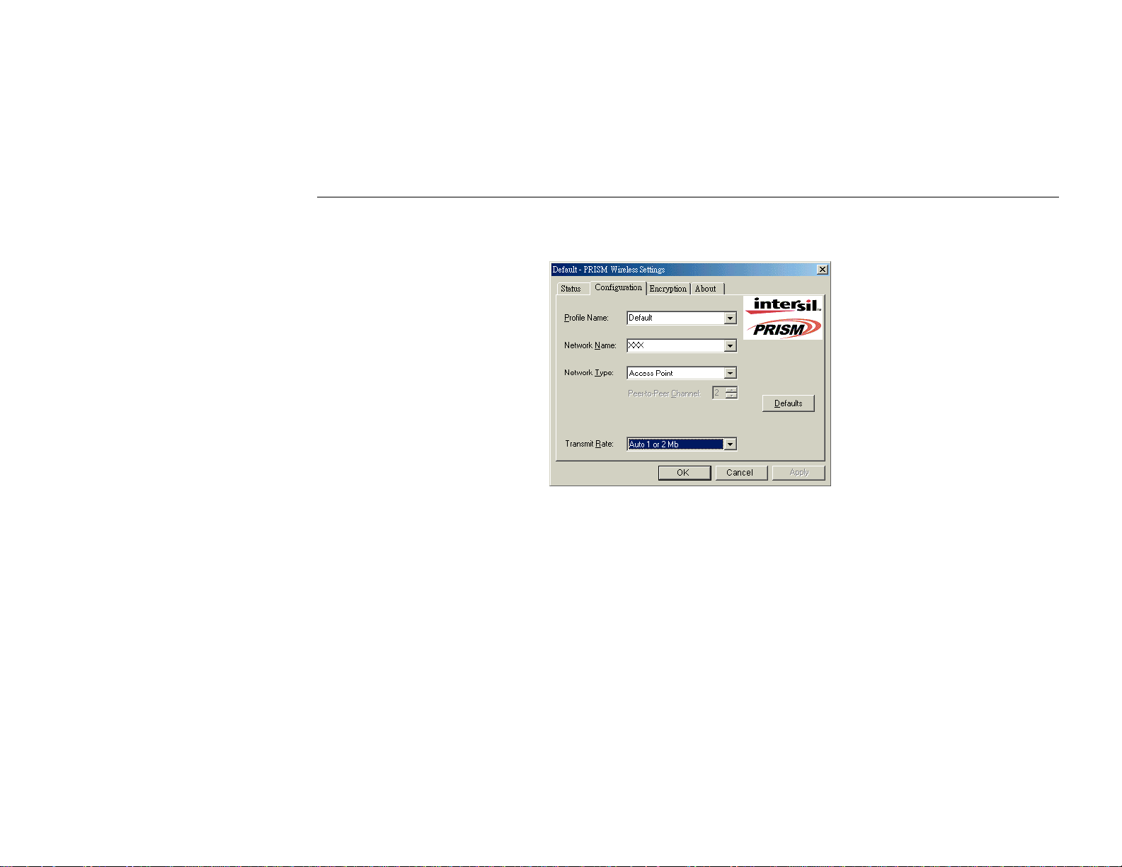
Configuration
Profile Name: The profile feature allows you to save the current wireless settings to the
WLAN card. You can save mul tiple profiles for different network environment and easily
retrieve the required one as needed.
In the Profile Name filed, enter a proper name to identify this network setting. After you
finish all the settings on this tab, click the Apply button.
To restore the required configuration, just click the drop-down menu to retrieve the preferred
profile. The current profile is indicated by the heading of the utility, e.g., “Default - PRISM
Wireless Settings” or “Office - PRISM Wireless Settings”.
Network Name: Also known as Service Set ID (SSID), it is the name of the Wireless LAN
group you want to participate in. All wireless clients must use the same network name in order
to communicate with each other.
Notice that under Access Point type, if the special SSID name “Any” is used, your Wireless
LAN Card will connect to the first compatible and “open” Access Point within the connection
range. It allows your Wireless LAN Card to wander across networks with different SSID.
14
Page 25

Chapter 3 Configuring Wireless LAN Card Settings
Network Type: You can connect your WLAN card to a network in one of the following two
ways:
Peer-to-Peer
(Ad Hoc Mode)
Access Point
(Infrastructure Mode)
Connecting to other Wireless LAN Card equipped computers,
forming a wirele ss network.
Connecting to a wired/wireless network through an Access
Point.
Peer-to-Peer Channel: Select the operating radio channel used to communicate with another
WLAN card. This field is not applicable if you are using Access Point (Infrastructure) network
type. Instead, the Wireless LAN Card will automatically scan for the right channel at which
the Access Point operates.
Transmit Rate: Select the speed (bit rate) that will be used for transmitting wireless data.
Owing to the RF modulation characteristics, the 1 Mbps operatio n speed sustains a longer
working range than 2 Mbps and like wise. Select the proper operation speed that best meets
your throughput and working range requirement.
Defaults: This button allows you to restore default settings.
15
Page 26
Mini PCI Wireless LAN / Modem Card User's Manua l
Figure 3-2 Peer-to-Peer Type Configuration
16
Page 27
Chapter 3 Configuring Wireless LAN Card Settings
Figure 3-3 Access Point Type Configuration
17
Page 28

Mini PCI Wireless LAN / Modem Card User's Manua l
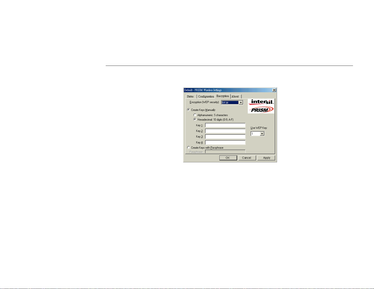
Encryption
Encryption technology is used to enhance wireless media security. Your encryption settings
must match those used by the Access Points or Wireless Stations (Peer-to-Peer mode) in your
network, or your computer will be unable to communicate with others of your network.
If you are not to use encryption, select Disabled from the Encryption drop-down menu. To
enable encryption, do the following:
1. Select the Encryption tab from the Wireless Settings utility.
2. Select your encryption type from 64 bit or 128 bit. The higher the bit numbe r, the greater
the complexity and the security of the encryption.
3. You can ge nerate your WEP encryption keys by manually entering keys o r using
passphrase. In either case, you should write down your WEP keys which may be needed
for other wireless devices. Here are the instructions for each method:
Create Keys Manually
For flexibility, you can enter the WEP keys in either Alphanumeric or Hexadecimal
format. Enable the preferred format and then enter the key values in the Key 1-4 fields.
Note that you need to enter all the four keys. The four keys, including the one selecte d as
WEB Key to use, are used to decrypt the data you receive.
18
Page 29

Chapter 3 Configuring Wireless LAN Card Settings
When using Hexadecimal format, only digits 0-9 and letters a-f, A-F are allo wed. Valid
key length for each encryption type is as below:
Alphanumeric Format Hexadecimal Format
64 bit 5 alphanumeric characters 10 hexadecimal digits
128 bit 13 alphanumeric characters 26 hexadecimal digits
Create Keys with Passphrase
To create keys by using passphrase, enter a text string with a maximum of 26
alphanumeric characters in the Passphrase field.
4. In the Use WEB Key box, select one o f the four keys to encrypt the data you are going
to transmit.
5. To have the new settings take effect, click Apply.
19
Page 30
Mini PCI Wireless LAN / Modem Card User's Manua l
Figure 3-4 PRISM Wireless Settings Utility – Encryption Tab
20
Page 31

About
Chapter 3 Configuring Wireless LAN Card Settings
About tab displays the basic information about the device, including the Network Driver,
Configuration Utility and NIC Firmware
Figure 3-5 PRISM Wireless Settings Utility – Version Tab
21
Page 32

Mini PCI Wireless LAN / Modem Card User's Manua l
PART 2. Using Windows XP Configuration Utility
Windows XP operating system includes Wireless Network Connection utility for wireless
configura tion and monitoring. You can choo s e to config ure your wireless network via either
the PRISM Wireless Settings utility as described in preceding section, or Windows XPincluded wireless utility. This section only provides the essential instructions on using
Windows XP wireless utility to get your wireless network established. For more information
please refe r to Windows XP on-line help.
Notice that only one configuration method can be used and Window XP utility is the default
configuration tool. In this situation, when you open the PRISM Wireless Settings utility, only
Status and About tabs are available.
If you are going to use the P RISM Wireless Settings utility, yo u should disable Windows XP
wireless utility as follows:
Double-click the wireless icon on system tray and click Advanced button. On the Wireless
Networks tab, uncheck the Use Windows t o configure my wireless network settings box
and click OK. This will restore your PRISM Wireless Settings utility with configuration tabs.
22
Page 33

Chapter 3 Configuring Wireless LAN Card Settings
Connecting to an Access Point or Wireless LAN Card
To connect to an existing Access Point/Wireless LAN Card (Peer-to-Peer mode), do the
following:
1. Right-click the Wireless Connection icon on the system tray and select View Available
Wireless Networks from the context menu.
Note: Depending on whether your wireless network is established, the co ntext menu may
come with different items.
2. When the Connect to Wireless Network window pops up, you will see all the Access
Points or Wireless LAN Cards (Peer-to-Peer mode) that are available in the air. Select
the wireless network you want to connect to .
23
Page 34

Mini PCI Wireless LAN / Modem Card User's Manua l
Figure 3-6 Windows XP – Connect to Wireless Network
3. If the target Access Point/Wireless LAN Card (Peer-to-Peer mode) has been set with
WEP key, you must enter t he same WEP key in the Net work key field. Otherwise, this
field is dimmed and you do not need to set up the WEP key.
4. Click Connect, then you will join the target network and this dialog window will
disappear. When your wireless connection is established, the connection icon appears as
below:
24
Page 35

Viewing Wireless Connection Status
After you successfully connect to the Access Point or Wireless LAN Card (Peer-to-Peer
mode), double-click the icon on the system tray again. This will open the Wireless Network
Connection Status window where you can see the general data of t he Wireless LAN Card,
such as Status, Duration, Speed and Signal Strength, etc.
Figure 3-7 Windows XP – Connection Status
Chapter 3 Configuring Wireless LAN Card Settings
25
Page 36

Page 37

Chapter 4 Country Selection for Mini PCI Modem Card
After modem driver installation, you may need to configure countries upon different
telecommunication laws/regulations. Ignore this chapter if your Mini PCI Card does not
support modem functions.
For Windows 98/Me
1. Double-click the Modems icon under Control Panel. Under General tab, highlight
Lucent Technologies Soft Modem AMR and then click Dialing Properties.
2. Select the country you locate from I am in this country/region list, then click Apply
and OK.
For Windows 2000/XP
1. Double-click the Phone and Modem Options icon under Control Panel. Under Dialing
Rules tab, highlight the location from which you are dialing and then click Edit.
2. Select the country you locate from the Country/region list, then click Apply and OK.
27
Page 38

Page 39

Chapter 5 Removing Wireless LAN/Modem Card Software
Should you need to uninstall the Wireless LAN Card utility software or modem software for
any reason, please proceed as follows. If your model supports 56K Modem function, both
Wireless LAN and Modem software are installed on your system. Removing either one of
them will not effect the operation of the other.
Removing Wireless LAN Card Software
For Windows 98/Me
1. Double-click the Add/Remove Programs icon under Control Panel.
2. Select IEEE 802.11b from the list and click Add/Remove.
3. Click OK to remove the components.
4. Click Finish and follow system prompts to complete uninstallation.
29
Page 40

Mini PCI Wireless LAN / Modem Card User's Manua l
For Windows 2000/XP
1. Double-click the Add/Remove Programs (or Add or Remove Programs for Windows
XP) icon und er Control Panel.
2. Highlight IEEE 802.11b from the list and then click Change/Remove.
3. When confirm message appears, click OK to remove the components.
4. Click Finish and follow system prompts to complete uninstallation.
Removing Mini PCI Modem Software
For Windows 98/Me
1. Double-click the Add/Remove Programs icon under Control Panel.
2. Select Lucent Technologies Soft M odem AMR from the list and click Add/Remove.
3. When warning message appears, click Yes to remove the components.
4. When prompted to restart your computer, select Yes.
For Windows 2000/XP
30
1. Double-click the Add/Remove Programs (or Add or Remove Programs for Windows
XP) icon under Control Panel.
Page 41

Chapter 5 Removing Wireless LAN/Modem Card Software
2. Highlight Lucent Technologies Soft Modem AMR from the list and then click
Change/Remove.
3. When warning message appears, click Yes to remove the components.
4. When prompted to restart your computer, select Yes.
31
Page 42

Page 43

Chapter 6 Commands Reference
Ignore this chapter if your Mini PCI Card does not support modem functions.
This chapter provides the AT command set for the Soft Modem chip set. Some of the
commands described within may not apply to your soft modem, depending on the build
options included in a license. The default values stated are typical for a full-featured Soft
Modem and may be different in reduced configurations.
6.1 Basic AT Command
A/—Repeat Last Command
A—Answer
Bn—Communication Standard Setting
B0 Selects CCITT V.22 mode when the modem is at 1200 bits/s.
B1 Selects Bell 212A when the modem is at 1200 bits/s (default).
33
Page 44

Mini PCI Wireless LAN / Modem Card User's Manua l
B2 Unselects V.23 reverse channel (same as B3).
B3 Unselects V.23 reverse channel (same as B2).
B15 Selects V.21 when the modem is at 300 bits/s.
B16 Selects Bell 103J when the modem is at 300 bits/s (default).
Cn—Carrier Control
C0 Transmit carrier always off (not supported).
C1 Normal transmit carrier switching (default).
Dn—Dial
En—Echo Command
E0 Disables echo command.
E1 Enables echo command (default).
Fn—On-Line Data Character Echo Command
F0 On-line data character echo enabled (not supported by LU97).
F1 On-line data character echo disabled.
Hn—Hook Control
H0 LU97 goes on-hook (default).
H1 LU97 goes off-hook.
34
Page 45

Chapter 6 Commands Reference
Ignore this chapter if your Mini PCI Card does not support modem functions.
This chapter provides the AT command set for the Soft Modem chip set. Some of the
commands described within may not apply to your soft modem, depending on the build
options included in a license. The default values stated are typical for a full-featured Soft
Modem and may be different in reduced configurations.
6.1 Basic AT Command
In—Request ID Information
I0, I3 Returns modem identity string and driver version number.
I1 Returns OK.
I2 Returns OK.
I4 Returns firmware version for the data pump.
I5 Returns the board/firmware ID and country ID in hexadecimal.
I6, I10 Returns OK for compatibility.
I7 Hardware version.
35
Page 46

Mini PCI Wireless LAN / Modem Card User's Manua l
I8 Codec version.
I9 Returns country ID in English.
I11 Displays connection information as described below.
Ln—Speaker Volume
L0 Low volume.
L1 Low volume.
L2 Med ium volume (default).
L3 High volume.
Mn—Speaker Control
M0 Speaker is off.
M1 Speaker is on until the modem detects the carrier signal (default).
M2 Speaker is always on when the modem is off-hook.
M3 Speaker is on until the carrier is detected, except when dialing.
Nn—Modulation Handshake
N0 When originating or answering, this is for handshake only at the communication
standard specified by register S37 and the Bn command.
N1 When originating or answering, begin the handshake only at t he communication
standard specified by S37 and the Bn command. During handshake, fallback to a
lower speed may occur (default).
36
Page 47

Chapter 6 Commands Reference
Ignore this chapter if your Mini PCI Card does not support modem functions.
This chapter provides the AT command set for the Soft Modem chip set. Some of the
commands described within may not apply to your soft modem, depending on the build
options included in a license. The default values stated are typical for a full-featured Soft
Modem and may be different in reduced configurations.
6.1 Basic AT Command
On—Return to On -Line Data Mode
O0 Instructs LU97 to exit on-line command mode and return to data mode.
O1 Issues a retrain before returning to on-line data mode.
O3 Issues a rate renegotiation before returning to on-line data mode.
Pn—Select Pulse Dialing
Qn—Result Code Control
Q0 Enables result codes (default).
37
Page 48

Mini PCI Wireless LAN / Modem Card User's Manua l
Q1 Disables result codes.
T—Select Tone Dialing
Vn—DCE Response Format
V0 Displays result codes as digits.
V1 Displays result codes as text (default).
Wn—Result Code Option
W0 CONNECT result code reports DTE receive speed. Disables pro tocol result codes.
W1 CONNECT result code reports DTE receive speed. Enables protoc ol result codes.
W2 CONNECT result code reports DCE receive speed. Enables protocol result codes
(default).
Xn— Extended Result Codes Control
Yn—Long-Space Disconnect
Y0 Disables long-space disconnect (default).
Y1 Enables long-space disconnect (not supported).
Zn—Reset and Recall Stored Profile
Z0 Reset and restore stored profile.
Z1 Reset and restore stored profile.
38
Page 49

Chapter 6 Commands Reference
Ignore this chapter if your Mini PCI Card does not support modem functions.
This chapter provides the AT command set for the Soft Modem chip set. Some of the
commands described within may not apply to your soft modem, depending on the build
options included in a license. The default values stated are typical for a full-featured Soft
Modem and may be different in reduced configurations.
6.1 Basic AT Command
Z2 Reset and restore stored profile.
&Bn—V.32 Auto Retrain
&B0 Disable V.32 auto retrain (not supported).
&B1 Enable V.32 auto retrain (default).
&Cn—Data Carrier Detect (DCD) Control
&C0 The state of the carrier from the remote modem is ignored. DCD remains on at all
times.
39
Page 50

Mini PCI Wireless LAN / Modem Card User's Manua l
&C1 DCD turns on when the remote modem’s carrier signal is detected and off when the
carrier signal is not detected (default).
&Dn—Data Terminal Ready (DTR) Control
&D0 Ignore the true status of DTR and treats it as always on. This should be used only if
the computer does not provide DTR to the modem.
&D1 If the DTR signal is not detected while in on-line data mode, the modem enters
command mode, issues the OK result code, and remains connected.
&D2 If the DTR signal is not detected while in on-line data mode, the modem disconnects
(default).
&D3 Reset modem on the on-to-off DTR transition.
&Fn—Restore Factory Default Configuration
&F0 Restores factory default configuration.
&Gn—V.22bis Guard Tone Control
&G0 Disables guard tone (default).
&G1 Selects 550 Hz guard tone.
&G2 Selects 1800 Hz guard tone.
&Jn—Auxiliary Relay Option
&J0 The auxiliary relay is never closed (default).
40
Page 51

Chapter 6 Commands Reference
Ignore this chapter if your Mini PCI Card does not support modem functions.
This chapter provides the AT command set for the Soft Modem chip set. Some of the
commands described within may not apply to your soft modem, depending on the build
options included in a license. The default values stated are typical for a full-featured Soft
Modem and may be different in reduced configurations.
6.1 Basic AT Command
&J1 Not supported.
&Kn—Local Flow Control Selection
&K0 Disables flow control.
&K1, &K2 Reserved.
&K3 Enables RTS/CTS (hardware) flow control (default).
&K4 Enables XON/XOFF flow control.
&Mn—Asynchronous Communications Mode
41
Page 52

Mini PCI Wireless LAN / Modem Card User's Manua l
&M0 Asynchronous mode (default).
&M1, &M2, &M 3, &M4 Reserved.
&Pn—Pulse Dial Make-to-Break Ratio Selection
&P0 Selects 39%—61% make/break ratio at 10 pulses per second.
&P1 Selects 33%—67% make/break ratio at 10 pulses per second (default).
&P2 Selects 33%—67% make/break ratio at 20 pulses per second.
&Qn—Asynchronous Communications Mode
&Q0 Asynchronous mode, buffered. Same as \N0.
&Q5 Error control mode, buffered (default). Same as \N3.
&Q6 Asynchronous mode, buffered. Same as \N0.
&Q8 MNP error control mode. If an MNP error control protocol is not established, the
modem will fall back according to the current user setting in register S36.
&Q9 V.42 or MNP error control mode. If neither error control protocol is established, the
modem will fall back according to the current user setting in register S36.
&Sn—Data Set Ready (DSR) Option
&S0 DSR is always on (default).
&S1 DSR comes on after establishing a connection and goes off when the connection ends.
42
&Tn—Self-Test Commands
Page 53

Chapter 6 Commands Reference
Ignore this chapter if your Mini PCI Card does not support modem functions.
This chapter provides the AT command set for the Soft Modem chip set. Some of the
commands described within may not apply to your soft modem, depending on the build
options included in a license. The default values stated are typical for a full-featured Soft
Modem and may be different in reduced configurations.
6.1 Basic AT Command
&T0 Abort. Terminates the test in progress.
&T1 Initializes local analog loopback, V.56 Loop 3. If a connection exist when this
command is issued, the modem hangs up. LU97 displays the Connect nnn message
at the start of the test.
&T3 Local digital loopback test, V.54 Loop2. If no connection exists, LU97 returns
ERROR.
&T6 Request a remote digital loop back, V.54 Loop 2 without self test. If no connection
exists, LU97 returns ERROR. The Connect nnn message is displayed.
43
Page 54

Mini PCI Wireless LAN / Modem Card User's Manua l
&Vn— Display Current Configuration
&Wn—Store Current Configuration
&W0 Stores the current configuration as profile 0.
&W1 Stores the current configuration as profile 1.
&Yn—Select Stored Profile for Hard Reset
&Y0 Select stored profile 0 on power-up.
&Y1 Select stored profile 1 on power-up.
&Zn=x—Store Telephone Number
\An—Select Maximum MNP Block Size
\A0 64 characters.
\A1 128 characters.
\A2 192 characters.
\A3 256 characters (default).
\Bn—Send Break
\Gn—Modem Port Flow Control
\G0 LU97 processes XON/XOFF flow control characters locally (default).
\G1 LU97 passes XON/XOFF flow control characters.
44
Page 55

Chapter 6 Commands Reference
Ignore this chapter if your Mini PCI Card does not support modem functions.
This chapter provides the AT command set for the Soft Modem chip set. Some of the
commands described within may not apply to your soft modem, depending on the build
options included in a license. The default values stated are typical for a full-featured Soft
Modem and may be different in reduced configurations.
6.1 Basic AT Command
\Jn—Adjust Bits/s Rate Control
\J0 Buffer mode. Error control is set or disabled with the \Nn command (default).
\J1 Forces the maximum DCE rate to the DTE rate.
\Kn—Set Break Control
When Modem Is Operating in Data Transfer Mode
\K0, \K2, K4 Enter on-line command mode. No break is sent to the remote modem.
\K1 Clear data buffers and send a break to the remote modem.
\K3 Send a break to the remote modem immediately.
45
Page 56

Mini PCI Wireless LAN / Modem Card User's Manua l
\K5 Send a nondestruc tive, nonexpedited break to the remote modem (default) .
When Modem Is On-Line Command State During Data Connection
\K0, \K1 Clear data buffers and send a break to the remote modem.
\K2, \K3 Send a break to the remote modem immediately.
\K4, \K5 Send a break to the remote modem in sequence with data (default).
When Break Is Received During Connection
\K0, \K1 Clear data buffers and send a break to the DTE.
\K2, \K3 Send a break to the DTE immediately.
\K4, \K5 Send a break to the DTE in sequence with received data (default).
\Nn—Select Error Control Mode
\N0 Buffer mode. No error control (same as &Q6).
\N1 Direct mode.
\N2 MNP or disconnect mode. The modem attempts to connect using MNP 2—4 error
control procedures. If this fails, the modem disconnects. This is also known as MNP
reliable mode.
46
Page 57

Chapter 6 Commands Reference
Ignore this chapter if your Mini PCI Card does not support modem functions.
This chapter provides the AT command set for the Soft Modem chip set. Some of the
commands described within may not apply to your soft modem, depending on the build
options included in a license. The default values stated are typical for a full-featured Soft
Modem and may be different in reduced configurations.
6.1 Basic AT Command
\N3 V.42, MNP, or buffered (default). LU97 attempts to connect in V.42 error control
mode. If this fails, it will attempt to connect in MNP mode. If this also fails, LU97
connects in buffer mode and continues operation.
\N4 V.42 or disconnect. The modem attempts to connect in V.42 error control mode. If
this fails, the modem disconnects.
\N5 V.42, MNP, or buffered (same as \N3).
\N7 V.42, MNP, or buffered (same as \N3).
\Qn—Local Flow Control Selection
47
Page 58

Mini PCI Wireless LAN / Modem Card User's Manua l
\Q0 Disable flow control (same as &K0).
\Q1 XON/XOFF software flow control (same as &K4).
\Q2 CTS-only flow control. This is not supported and the response is ERROR.
\Q3 RTS/CTS to DTE (same as &K3) (default).
\Rn—Ring Indicator Signal Off After Answer
\R0 Ring indicator signal is off after the telephone call is answered.
\Tn—Inactivity Timer
\T0 Inactivity timer disabled (default).
\T1—\T255 Specifies the length of time in minutes that the modem will wait before
\Vn—Protocol Result Code
\V0 Disables protocol result code appended to DCE speed.
\V1 Enables protocol result code appended to DCE speed (default).
\V2 Enables protocol result code appended to DCE speed (same as \V1).
%B—View Numbers in Blacklist
%Cn—Data Compression Control
%C0 V.42bis/ MNP 5 disabled. No data compression.
disconnecting when no data is sent or received.
48
Page 59

Chapter 6 Commands Reference
Ignore this chapter if your Mini PCI Card does not support modem functions.
This chapter provides the AT command set for the Soft Modem chip set. Some of the
commands described within may not apply to your soft modem, depending on the build
options included in a license. The default values stated are typical for a full-featured Soft
Modem and may be different in reduced configurations.
6.1 Basic AT Command
%C3 V.42bis/ MNP 5 enabled. Data compression enabled (default).
%En—Auto Fallback/Fallforward Control
%E0 Disable fallback/fallforward.
%E1 Enable fallback and disable fallforward.
%E2 Enable fallback/fallforward (default).
-Cn—Data Calling Tone
-C0 Disabled (default).
49
Page 60

Mini PCI Wireless LAN / Modem Card User's Manua l
-C1 Enabled.
-V90—Enable/Disable V.90 Settings
-V90=X Controls the downstream rate.
-V90=0 Disables V.90.
-V90=1 Enables V.90 auto rate (default).
-V90? Displays the current value.
-V90=? Shows the range of X (0, 1).
6.2 Result Codes
The AT command handler responds to commands from the caller and to activity on the line
via result codes.
Two forms of each result code are available. The long-form, or verbose, response is given
when V1 is selected, and the short-form, data-like numeric response is given when V0 is
selected. The long-form code is preceded and terminated by the sequence <CR> <LF>. The
short-form is also terminated by <CR>, but it has no preceding sequence. If result codes are
suppressed, nothing is returned to the caller.
50
Result
Code
OK 0 Acknowledges the execution of a command line.
Numeric
Code
Description
Page 61

Chapter 6 Commands Reference
Ignore this chapter if your Mini PCI Card does not support modem functions.
This chapter provides the AT command set for the Soft Modem chip set. Some of the
commands described within may not apply to your soft modem, depending on the build
options included in a license. The default values stated are typical for a full-featured Soft
Modem and may be different in reduced configurations.
6.1 Basic AT Command
Code
Result
CONNECT 1 Modem connected to line.
RING 2 Incoming ring signal has been detected.
NO CARRIER 3 Modem lost carrier signal, does not detect carrier
ERROR 4 Invalid command.
CONNECT 1200 EC* 5 Connection at 1200 bits/s.
NO DIALTONE 6 No dial tone detected.
Numeric
Code
Description
signal, or does not detect answer tone.
51
Page 62

Mini PCI Wireless LAN / Modem Card User's Manua l
Code
Result
BUSY 7 Busy signal detected.
NO ANSWER 8 Remote end never answered.
CONNECT 2400 EC* 10 Connection at 2400 bits/s.
CONNECT 4800 EC* 11 Connection at 4800 bits/s.
CONNECT 9600 EC* 12 Connection at 9600 bits/s.
CONNECT 14400 EC* 13 Connection at 14400 bits/s.
CONNECT 19200 EC* 14 Connection at 19200 bits/s.
CONNECT 7200 EC* 24 Connection at 7200 bits/s.
CONNECT 12000 EC* 25 Connection at 12000 bits/s.
CONNECT 16800 EC* 86 Connection at 16800bits/s.
CONNECT 300 EC* 40 Connection at 300 bits/s.
CONNECT 21600 EC* 55 Connection at 21600 bits/s.
CONNECT 24000 EC* 56 Connection at 24000 bits/s.
CONNECT 26400 EC* 57 Connection at 26400 bits/s.
CONNECT 28800 EC* 58 Connection at 28800 bits/s.
CONNECT 31200 EC* 59 Connection at 31200 bits/s.
CONNECT 33600 EC* 60 Connection at 33600 bits/s.
CONNECT 38400 EC* 28 Connection at 38400 bits/s (DTE rate).
Numeric
Code
Description
52
Page 63

Chapter 6 Commands Reference
Ignore this chapter if your Mini PCI Card does not support modem functions.
This chapter provides the AT command set for the Soft Modem chip set. Some of the
commands described within may not apply to your soft modem, depending on the build
options included in a license. The default values stated are typical for a full-featured Soft
Modem and may be different in reduced configurations.
6.1 Basic AT Command
Code
Result
CONNECT 57600 EC* 18 Connection at 57600 bits/s (DTE rate).
CONNECT 115200 EC* 87 Connection at 115200 bits/s (DTE rate).
DELAYED 88 Delay is in effect for the dialed number.
BLACKLISTED 89 Dialed number is blacklisted.
BLACKLIST FULL 90 Blacklist is full.
CONNECT 32000 EC* 70 Connection at 32000 bits/s (K56flex mode) or V.90.
Numeric
Code
Description
53
Page 64

Mini PCI Wireless LAN / Modem Card User's Manua l
Code
Result
CONNECT 34000 EC* 71 Connection at 34000 bits/s (K56flex mode).
CONNECT 36000 EC* 72 Connection at 36000 bits/s (K56flex mode) or V.90.
CONNECT 38000 EC* 73 Connection at 38000 bits/s (K56flex mode).
CONNECT 40000 EC* 74 Connection at 40000 bits/s (K56flex mode) or V.90.
CONNECT 42000 EC* 75 Connection at 42000 bits/s (K56flex mode).
CONNECT 44000 EC* 76 Connection at 44000 bits/s (K56flex mode) or V.90.
CONNECT 46000 EC* 77 Connection at 46000 bits/s (K56flex mode).
CONNECT 48000 EC* 78 Connection at 48000 bits/s (K56flex mode) or V.90.
CONNECT 50000 EC* 79 Connection at 50000 bits/s (K56flex mode).
CONNECT 52000 EC* 80 Connection at 52000 bits/s (K56flex mode) or V.90.
CONNECT 54000 EC* 81 Connection at 54000 bits/s (K56flex mode).
CONNECT 56000 EC* 82 Connection at 56000 bits/s (K56flex mode).
CONNECT 28000 EC* 100 Connection at 28000bits/s (V.90 mode).
CONNECT 29333 EC* 101 Connection at 29333 bits/s (V.90 mode).
CONNECT 30666 EC* 102 Connection at 30666 bits/s (V.90 mode).
CONNECT 33333 EC* 103 Connection at 33333bits/s (V.90 mode).
CONNECT 34666 EC* 104 Connection at 34666 bits/s (V.90 mode).
CONNECT 37333 EC* 105 Connection at 37333 bits/s (V.90 mode).
Numeric
Code
Description
54
Page 65

Chapter 6 Commands Reference
Ignore this chapter if your Mini PCI Card does not support modem functions.
This chapter provides the AT command set for the Soft Modem chip set. Some of the
commands described within may not apply to your soft modem, depending on the build
options included in a license. The default values stated are typical for a full-featured Soft
Modem and may be different in reduced configurations.
6.1 Basic AT Command
Code
Result
CONNECT 38666 EC* 106 Connection at 38666 bits/s (V.90 mode).
CONNECT 41333 EC* 107 Connection at 41333 bits/s (V.90 mode).
CONNECT 42666 EC* 108 Connection at 42666 bits/s (V.90 mode).
CONNECT 45333 EC* 109 Connection at 45333 bits/s (V.90 mode).
CONNECT 46666 EC* 110 Connection at 46666 bits/s (V.90 mode).
CONNECT 49333 EC* 111 Connection at 49333 bits/s (V.90 mode).
Numeric
Code
Description
55
Page 66

Mini PCI Wireless LAN / Modem Card User's Manua l
CONNECT 50666 EC* 112 Connection at 50666 bits/s (V.90 mode).
CONNECT 53333 EC* 113 Connection at 53333 bits/s (V.90 mode).
CONNECT 54666 EC* 114 Connection at 54666 bits/s (V.90 mode).
* EC only appears when the extended result codes configuration option is enabled. EC is
replaced by one of the following symbols, depending on the error control method used:
•
•
•
•
•
6.3 S-Registers
The following table provides a summary of the S-registers.
Register Description Range Base
S0 Auto-answering number. 0—255 rings 0 †
S1 Ring counter. 0—255 rings 0
Result
Code
Numeric
Code
Description
V42bis—V.42 error control and V.42bis data compression.
V42—V.42 error control only.
MNP 5— MNP class 4 error control and MNP class 5 data compression.
MNP 4— MNP class 4 error control only.
NoEC—no error control protocol.
Default*
Unit
56
Page 67

Chapter 6 Commands Reference
Ignore this chapter if your Mini PCI Card does not support modem functions.
This chapter provides the AT command set for the Soft Modem chip set. Some of the
commands described within may not apply to your soft modem, depending on the build
options included in a license. The default values stated are typical for a full-featured Soft
Modem and may be different in reduced configurations.
6.1 Basic AT Command
Register Description Range
S2 AT escape character (user defined) 0—255 ASCII 43(2Bh)
S3 Carriage return character. 0—127 ASCII 13(0Dh)
S4 Line feed character. 0—127 ASCII 10(0Ah)
S5 Back space character. 0—255 ASCII 8(08h)
S6 Time for dial tone. 3—255 s 3 †
S7 Wait time for carrier. 1—255 s 50 †
Base
Unit
Default*
57
Page 68

Mini PCI Wireless LAN / Modem Card User's Manua l
Register Description Range Base
Unit
S8 Pause time for dial delay modifier. 0—255 s 2 †
S9 Reserved. — — —
S10 Reserved. — — —
S11 DTMF tone duration. 50—255 ms 95 †
S12 Escape guard time. 0—255 20 ms 50
S14 General bit-mapped options status:
command echo, quiet mode, result codes,
tone/pulse.
S20 Sync underrun fill character. 0—255 — 0
S21 V.24/general bit-mapped options status:
DTR behavior, DCD behavior.
S22 Speaker/results bit-mapped options
status:speaker volume, speaker control,
limit result codes, pulse dial make/break
ratio.
S23
S27 General bit-mapped options status: V.90
General bit-mapped options status: guard
tone type, busy cycles, bell mode
permitted flag, ABCD dialing permitted.
upstream at 3429 Hz, remote digital loop-
back request handling, bell compatibility
mode, maximum DCE speed.
— — 138(10001010b)
— — 48(00110000b)
— — 70(01000110b)
— — 54(00110101b)
— — 73(01001001b)
Default*
58
Page 69

Chapter 6 Commands Reference
Ignore this chapter if your Mini PCI Card does not support modem functions.
This chapter provides the AT command set for the Soft Modem chip set. Some of the
commands described within may not apply to your soft modem, depending on the build
options included in a license. The default values stated are typical for a full-featured Soft
Modem and may be different in reduced configurations.
6.1 Basic AT Command
Register Description Range
S28
S29 Flash dial modifier time. 0—255 10 ms 70
S30 Inactivity timer. 0—255 10 s 0
S32 Xon character. 0—255 ASCII 17 (11h)
S33 Xoff character. 0—255 ASCII 19 (13h)
S35 Reserved. — — —
General bit-mapped options status: pulse
dialing, mode selection.
— — 160(10100000b)
Base
Unit
Default*
59
Page 70

Mini PCI Wireless LAN / Modem Card User's Manua l
Register Description Range Base
Unit
S36 LAPM failure control. — — 7
S37 Line connection speed. — — 0
S42 Reserved. — — —
S43 Reserved. — — —
S48 V.42 Negotiation Control — — 7
S53 General bit-mapped options: Calling tone
flag, off-hook restrictions, blind dial pause,
dial modifier validation, pulse and dial tone
in same di al string.
S54 Blind dialing delay 2—255 — 2
S56 General bit-mapped options. — — 0
S63 Fault break Length 0—254 10ms 30
S90 Reserved. — — —
S91 PSTN transmit attenuation level. 6—25 -dB 10
S92 FAX transmit attenuation level. 6—25 dB 10
S93 DTMF transmit attenuation level. 5—25 dB 6
S94
DTMF transmit attenuation level for high
DTMF group.
——47
0—25 dB 0
*. Values presented in decimal except were noted.
†. Values are country-specific.
Default*
60
Page 71

Chapter 6 Commands Reference
Ignore this chapter if your Mini PCI Card does not support modem functions.
This chapter provides the AT command set for the Soft Modem chip set. Some of the
commands described within may not apply to your soft modem, depending on the build
options included in a license. The default values stated are typical for a full-featured Soft
Modem and may be different in reduced configurations.
6.1 Basic AT Command
6.4 Fax Command
The soft modem supports FAX commands conforming to EIA standard 578. These commands
are given her e with short descriptio ns; complete explanations are given i n the standar d,
available from the Electronic Industries Association.
+FCLASS?—Service Class Indication
+FCLASS=?—Service Class Capabilities
61
Page 72

Mini PCI Wireless LAN / Modem Card User's Manua l
+FCLASS=n—Service Class Selection
+FCLASS=0 Select data mode. (Default.)
+FCLASS=1 Select FAX Class 1
+FTS=n—Transmission Silence
+FRS=n—Receive Silence
+FTM=n—Transmit FAX Data with n Carrier
Command Modulation Speed
+FTM=3 V.21 channel 2 300 bits/s.
+FTM=24 V.27ter. 2400 bits/s.
+FTM=48 V.27ter. 4800 bits/s.
+FTM=72 V.29. 7200 bits/s.
+FTM=96 V.29. 9600 bits/s.
+FTM=73 V.17 7200 bits/s.
+FTM=74 V.17 (short train). 7200 bits/s.
+FTM=97 V.17. 9600 bits/s.
+FTM=98 V.17 (short train). 9600 bits/s.
+FTM=121 V.17. 12000 bits/s.
+FTM=122 V.17 (short train). 12000 bits/s.
+FTM=145 V.17. 14400 bits/s.
+FTM=146 V.17 (short train). 14400 bits/s.
62
+FRM=n—Receive Data
Page 73

Chapter 6 Commands Reference
Ignore this chapter if your Mini PCI Card does not support modem functions.
This chapter provides the AT command set for the Soft Modem chip set. Some of the
commands described within may not apply to your soft modem, depending on the build
options included in a license. The default values stated are typical for a full-featured Soft
Modem and may be different in reduced configurations.
6.1 Basic AT Command
Command Modulation Speed
+FRM=3 V.21 channel 2 300 bits/s.
+FRM=24 V.27ter. 2400 bits/s.
+FRM=48 V.27ter. 4800 bits/s.
+FRM=72 V.29. 7200 bits/s.
+FRM=96 V.29. 9600 bits/s.
+FRM=73 V.17. 7200 bits/s.
+FRM=74 V.17 (short train). 7200 bits/s.
+FRM=97 V.17. 9600 bits/s.
+FRM=98 V.17 (short train). 9600 bits/s.
+FRM=121 V.17. 12000 bits/s.
63
Page 74

Mini PCI Wireless LAN / Modem Card User's Manua l
+FRM=122 V.17 (short train). 12000 bits/s.
+FRM=145 V.17. 14400 bits/s.
+FRM=146 V.17 (short train). 14400 bits/s.
+FTH=n—Transmit HDLC Data with n Carrier
Command Modulation Speed
+FTH=3 V.21 Channel 2. 300 bits/s.
+FTH=24 V.27ter. 2400 bits/s.
+FTH=48 V.27ter. 4800 bits/s.
+FTH=72 V.29. 7200 bits/s.
+FTH=96 V.29. 9600 bits/s.
+FTH=73 V.17. 7200 bits/s.
+FTH=74 V.17 (short train). 7200 bits/s.
+FTH=97 V.17. 9600 bits/s.
+FTH=98 V.17 (short train). 9600 bits/s.
+FTH=121 V.17. 12000 bits/s.
+FTH=122 V.17 (short train). 12000 bits/s.
+FTH=145 V.17. 14400 bits/s.
+FTH=146 V.17 (short train). 14400 bits/s.
+FRH=n—Receive HDLC Data with n Carrier
Command Modulation Speed
+FRH=3 V.21 Channel 2. 300 bits/s.
+FRH=24 V.27ter. 2400 bits/s.
64
Page 75

Chapter 6 Commands Reference
Ignore this chapter if your Mini PCI Card does not support modem functions.
This chapter provides the AT command set for the Soft Modem chip set. Some of the
commands described within may not apply to your soft modem, depending on the build
options included in a license. The default values stated are typical for a full-featured Soft
Modem and may be different in reduced configurations.
6.1 Basic AT Command
+FRH=48 V.27ter. 4800 bits/s.
+FRH=72 V.29. 7200 bits/s.
+FRH=96 V.29. 9600 bits/s.
+FRH=73 V.17. 7200 bits/s.
+FRH=74 V.17 (short train). 7200 bits/s.
+FRH=97 V.17. 9600 bits/s.
+FRH=98 V.17 (short train). 9600 bits/s.
+FRH=121 V.17. 12000 bits/s.
+FRH=122 V.17 (short train). 12000 bits/s.
+FRH=145 V.17. 14400 bits/s.
+FRH=146 V.17 (short train). 14400 bits/s.
65
Page 76

Mini PCI Wireless LAN / Modem Card User's Manua l
+FPR=n—Select FAX Port Rate
DTE Command DCE Action Description
+FPR=0 Execute +IPR=0. Select automatic rate detection.
+FPR=1 Execute +IPR=2400. Set DTE-DCE to 2400 bits/s.
+FPR=2 Execute +IPR=4800. Set DTE-DCE to 4800 bits/s.
+FPR=4 Execute +IPR=9600. Set DTE-DCE to 9600 bits/s.
+FPR=8 Execute
+FPR=10 Execute
+FPR=18 Execute
+FPR=? (if all values listed
above are supported)
+FPR? (if +IPF=0) Report 0. DTE-DCE rate is automatically detected.
+FPR? (if +IFC=2400) Report 1. DTE-DCE rate is 2400 bits/s.
+FPR? (if +IFC=4800) Report 2. DTE-DCE rate is 4800 bits/s.
+FPR? (if +IFC=9600) Report 4. DTE-DCE rate is 9600 bits/s.
+FPR? (if +IFC=19200 Report 8. DTE-DCE rate is 19200 bits/s.
+FPR? (if +IFC=38400) Report 10. DTE-DCE rate is 38400 bits/s.
+FPR? (if +IFC=57600) Report 18. DTE-DCE rate is 57600 bits/s.
+FPR? (all other +IPR
setting)
Set DTE-DCE to 19200 bits/s.
+IPR=19200.
Set DTE-DCE to 38400 bits/s.
+IPR=38400.
Set DTE-DCE to 57600 bits/s.
+IPR=57600.
Report (0, 1, 2, 4, 8,
10, 18)
Report 255. Indicates invalid setting.
DCE supports 2400 bits/s, 4800 bits/s,
9600 bits/s, 19200 bits/s, 38400 bits/s,
and 57600 bits/s.
66
Page 77

Chapter 6 Commands Reference
Ignore this chapter if your Mini PCI Card does not support modem functions.
This chapter provides the AT command set for the Soft Modem chip set. Some of the
commands described within may not apply to your soft modem, depending on the build
options included in a license. The default values stated are typical for a full-featured Soft
Modem and may be different in reduced configurations.
6.1 Basic AT Command
+FAA=n—Adaptive Answer
+FAA=0 The DCE will answer only as a Class 1 FAX device. No automatic switching
of service class will occur based on the calling device type.
+FAA=1 The DCE can answer and automatically determine whether to answer as a
facsimile DCE or as a data modem.
+FMI—Manufacturer Identification
67
Page 78

Mini PCI Wireless LAN / Modem Card User's Manua l
+FMM—Product Identification
+FMR—Version/Revision Information
68
Page 79

Chapter 7 Troubleshooting
For Wireless LAN Card
Radio Interference
You may be able to eliminate any interference by trying the following:
•
Increase the distance between the wireless computers and the device causing the radio
interference.
•
Plug the computer equipped with the Wireless LAN Card into an outlet on a different
branch circuit from that used by the affecting device.
•
Consult the dealer or an experienced radio technician for help.
•
Keep the computer with the Wireless LAN Card away from the microwave oven and
large metal objects.
69
Page 80

Mini PCI Wireless LAN / Modem Card User's Manua l
Cannot Connect to Another Wireless LAN Card
If you cannot make a connection to another Wire less LAN Card from your computer, it co uld
be due to one of the following reasons:
•
Incorrect SSID. Make sure the SSID is the same for all computers that have a Wireless
LAN Card.
•
Changes are not being recognized by your computer. Restart your computer.
•
If in Peer-To-Peer mode, make sure the Log on to Windows NT domain check box is
not selected in the Client for Microsoft Networks Properties dialog box in the
Network Configuration tab.
•
Incorrect IP Address or Subnet Mask. Check these settings in the TCP/IP Properties
dialog box in the Network Configuration tab.
Poor Link Quality
If the Link Quality display stays in the Poor range, it could be due to one of the following
reasons:
•
Radio interference.
•
Distance between Wireless LAN Card and Access Point is too far. Decrease the
distance between the Wireless LAN Card and Access Point (or another card).
70
Page 81

Chapter 6 Commands Reference
Ignore this chapter if your Mini PCI Card does not support modem functions.
This chapter provides the AT command set for the Soft Modem chip set. Some of the
commands described within may not apply to your soft modem, depending on the build
options included in a license. The default values stated are typical for a full-featured Soft
Modem and may be different in reduced configurations.
6.1 Basic AT Command
Cannot Connect to Access Point
If you cannot make a connection to the Access Point, it could be due to one of the following
reasons:
•
Make sure the Wireless LAN Card and Access Point have no physical connection
problems.
•
Make sure the SSID for the Wireless LAN Card is the same as the Access Point.
•
Make sure the privacy type is the same as that of Access Point. Also, make sure the
Default Key is the same for both computers.
71
Page 82

Mini PCI Wireless LAN / Modem Card User's Manua l
For Modem Card
No Response From Your Modem
•
Make sure that you have chosen the appropriate COM port for your modem and which
does not conflict with other ports in your PC system.
•
Check if there is any other interface cards in your computer that use the same COM
port as your modem. If so, you must set your modem to another COM port.
Your Modem Does Not Connect After It Has Dialed a Phone Number
•
The phone line may be too noisy or the telephone cord may be poor. Try the line with a
regular phone. Also, the remote modem may not recognize your modem’s baud rate.
Can’t Transmit After Connectin g to the Remote Modem
•
Check the communication parameters of the remote modem, then configure your
software to the same number of data bits, stop bit and parity.
72
Page 83

Appendix A Limited Warranty
Wireless LAN/Modem Card Hardware
The seller warrants to the end user (“Customer”) that this hardware product will be free from
defects in workmanship and materials, under normal use and service, for 1 year from the date
of purchase from the seller or its authorized reseller. The seller’s sole obligation under this
express warranty shall be, at the seller’s option and expense, to repair the defective product or
part, deliver to Customer an equivalent product or part to replace the defective item, or if
neither of the two foregoing options is reasonably available, The seller may, in its sole
discretion, refund to the Customer the purchase price paid for the defective product. All
products that are replaced will become the property of the seller. Replacement products may
be new or reconditioned.
73
Page 84

Mini PCI Wireless LAN / Modem Card User's Manua l
Wireless LAN/Modem Software
The seller warrants to Customer that each software program licensed from it , except as noted
below, will perform in substantial conformance to its program specifications, for a period of 1
year from the date of purchase from the seller or its authorized reseller. The seller warrants the
media containing software against failure during the warranty period. No updates are provided.
The seller’s sole obligation under this express warranty shall be, at the seller’s option and
expense, to refund the purchase price paid by Customer for any defective software product, or
to replace any defective media with software which substantially conforms to applicable seller
published specifications. Customer assumes responsibility for the selection of the appropriate
application programs and associated reference materials. The seller makes no warranty or
representation that its software products will meet Customer’s requirements or work in
combination with any hardware or software applications products provided by third parties,
that the operation of the software products will be uninterrupted or error free, or that all
defects in the software products will be corrected. For any third party products listed in the
seller software product documentation or specifications as being compatible, the seller will
make reasonable efforts to provide compatibility, except where the non-compatibility is
caused by a defect in the third party’s product or from use of the software product not in
accordance with the seller’s published specifications or user manual.
74
Page 85

Appendix B Regulatory Compliance
FCC Part 15 Declaration of Conformity (DoC)
This device complies with the requirements of FCC Part 15 rules. The operation is subject to
the following two conditions:
1. This device may not cause harmful i nterference, and
2. This device must accept any interference received, including interference that may cause
undesired operation.
75
Page 86

Mini PCI Wireless LAN / Modem Card User's Manua l
FCC Rules and Regulations - Part 15
Warning: This device has been tested and found to comply with the limits for a Class B digital device
pursuant to Part 15 of the Federal Communications Commissions Rules and Regulation. These limits are
designed to provide reasonable protection against harmful interference when the equipment i s operated
in a residential environment. This equipment generates, uses, and can radiate radio frequency energy and,
if not installed and used in accordance with the instructio n manual, may cause harmful interferen ce to
radio communications.
However, there is no guarantee that interference will not occur in a particular installation. If this
equipment does cause harmful i nterference to radio or television reception, which can be determined by
turning the equipment off and on, the user is encouraged to tr y and correct the interference by one or
more of the following measures:
•
Reorient or relocate the receiving antenna.
•
Increase the separation between the equipment and receiver.
•
Connect the equipment into an outlet on a circuit different from that to which the
receiver is connected.
•
Consult the dealer or an experienced radio / TV technician for help.
76
Page 87

FCC Radiation Exposure Statement
This equipment complies with FCC radiation exposure limits set forth for an uncontrolled
environment. This equipment should be installed and operated with minimum distance of
20cm between the radiator & your body.
This transmitter must not be co-located or operating in conjunction with any other antenna or
transmitter.
FCC Caution:
To assure continued compliance, (example – use only shielded interface cables when
connecting to computer or peripheral devices ) any changes or modifications not expressly
approved by the party responsible for compliance could void the user’s authority to operate
this equipment.
Appendix B Regulatory Compliance
77
Page 88

Mini PCI Wireless LAN / Modem Card User's Manua l
Installation Guidance
Once this module has been integrated into tha host notebook, be sure that the antenna has to be integral and located on top portion
of both sides of the LCD panel. The antenna has to be maintained at least 20cm separation with the human body.
This device is intended only for OEM integrators under the following conditions:
1) The antenna must be installed such that 20 cm is maintained between the antenna and users, and
2) The transmitter module may not be co-located with any other transmitter or antenna.
As long as the 2 conditions above are met, further transmitter testing will not be required. However, the OEM integrator
is still responsible for testing their end-product for any additional compliance requirements required with this module
installed (for example, digital device emissions, PC peripheral requirements, etc.).
IMPORTANT NOTE: In the event that these conditions can not be met (for example certain laptop configurations or
co-location with another transmitter), then the FCC authorization is no longer considered valid and the FCC ID can not
be used on the final product. In these circumstances, the OEM integrator will be responsible for re-evaluating the end
product (including the transmitter) and Obtaining a separate FCC authorization.
End Product Labelling
This transmitter module is authorized only for use in devices where the antenna may be installed such that 20 cm
may be maintained between the antenna and users (for example access points, routers, wireless ASDL modems, and
similar equipment). The final end product must be labeled in a visible area with the following: “ Contains TX FCC
ID: H8NWLL030M ”.
78
Page 89

Appendix B Regulatory Compliance
Manual Information That Must be Included
The users manual for end users must include the following information in a prominent location “ IMPORTANT NOTE:
To comply with FCC RF exposure compliance requirements, the antenna used for this transmitter must be
installed to provide a separation distance of at least 20 cm from all persons and must not be co-located or operating
in conjunction with any other antenna or transmitter.”
79
Page 90

Page 91

Appendix C Setting Up TCP/IP
This section contains instructions for configuring the TCP/IP protocol of the Wireless LAN
Card. The IP address policy depends on your wireless network. You should configure your
TCP/IP protocol as instructed by your network administrator.
1. On the taskbar, select Start > Settings > Control Panel, double-click the Network icon.
2. Click the Configuration tab of the Network dialog box.
3. In the network components list, select the TCP/IP protocol of your Wireless LAN Card,
e.g., TCP/IP ->Intersil PRISM Wireless LAN PCI Card, and then click Properties.
81
Page 92

Mini PCI Wireless LAN / Modem Card User's Manua l
For correct IP address
information for your
wireless LAN installation,
contact your net wor k
administrator.
For more information on IP
addresses, see the Network
Working Group
Specification RFC 1918 on
the Internet.
4. On the IP Address tab, choose one of the methods as required:
Option A: Click Specify an IP address.
In the IP Address box, enter a valid four-component IP address, either a public or
private one as required. If private IP address is used, the following three blocks of IP
addresses are available for private networks:
10. 0 . 0. 0 — 10.255.255.255
172. 16. 0. 0 — 172. 31.255.255
192.168. 0. 0 — 192.168.255.255
In the Subnet Mask box, enter a valid four-component IP address.
82
Page 93

Appendix C Setting Up TCP/IP
Option B: Select Obtain an IP address automatically.
An IP address will be automatically assigned to your computer.
5. Click OK to return to Network dialog box and click OK again to finish configuration. If
your TCP/IP properties have been modified, you will be prompted to restart your
computer. Click Yes to have new settin g s take e f fec t.
83
Page 94

Page 95

Appendix D Specification
* Specifications are subject to change with notice.
Mini PCI Wireless LAN Card
Host interface Mini-PCI Spec. V1.0
Form factor Mini-PCI type IIIB
Wireless Chipset Intersil Prism 2.5 chipset ( ISL3874A+HFA3783+ISL3685+ISL3984)
Operation voltage +3.3V
Frequency Range 2.4GHz – 2.4835GHz
Channels Numbers
Channel spac ing 5MHz
Modulation Technique Direct Sequence Spread Spectrum(CCK,DQPSK,DBPSK)
Spreading 11-chip Barker sequence
Media Access Protocol CSMA/CA(Collision Avoidance) with ACK
Transfer data rate 11Mbps, 5.5Mbps, 2Mbps, 1Mbps, auto-rating
1 〜 11 channels for US
1 〜 13 channels for Europe
1 〜 13 or 14 channe ls for Japan
85
Page 96

Mini PCI Wireless LAN / Modem Card User's Manua l
Transmitter output power 14dbm
Receiver sensitivity
(FER <8%)
-84 dbm for 11 Mbps
Antenna type Internal diversity with connectors
Frame Error Rate (FER) Less than 8%
Security 64Bit WEP encryption, optional 128Bit RC4
Available Range
(in meters)
11 Mbps 5.5Mbps 2Mbps 1Mbps
Open Space 300m 450m 600m 650m
Semi Open Space 60m 80m 100m 120m
Closed Space 35m 45m 60m 60m
Power Consumption Continuous TX mode : 320 mA
Standby mode : 200mA
Power saving mode : 125mA
Operation Temperature Range
Storage Temperature Range
0〜55℃
-20〜75℃
OS Compatibility Windows 98, 2000, ME, XP
Standards IEEE 802.11b
86
Page 97

Appendix D Specification
Mini PCI Wireless LAN and Modem Card
A. Wireless Specifica tion
Host interface Mini-PCI Spec. V1.0
Form factor Mini-PCI type IIIA
Wireless Chipset Intersil Prism 2.5 chipset ( ISL3874A+HFA3783+ISL3685+ISL3984)
Operation voltage 3.3V
Frequency Range 2.4GHz – 2.4835GHz
Channels Numbers
Channel spac ing 5MHz
Modulation Technique Direct Sequence Spread Spectrum(CCK,DQPSK,DBPSK)
Spreading 11-chip Barker sequence
Media Access Protocol CSMA/CA(Collision Avoidance) with ACK
Transfer data rate 11Mbps, 5.5Mbps, 2Mbps, 1Mbps, auto-rating
Transmitter output power 14dbm
Receiver sensitivity
(FER <8%)
Antenna type Internal diversity with connectors
Frame Error Rate (FER) Less than 8%
Security 64Bit WEP encryption, optional 128Bit RC4
1 〜 11 channels for US
1 〜 13 channels for Europe
1 〜 13 or 14 channe ls for Japan
-80dbm for 11 Mbps
87
Page 98

Mini PCI Wireless LAN / Modem Card User's Manua l
Available Range
(in meters)
11 Mbps 5.5Mbps 2Mbps 1Mbps
Open Space 300m 450m 600m 650m
Semi Open Space 60m 80m 100m 120m
Closed Space 35m 45m 60m 60m
Power Consumption Continuous TX mode : 380 mA
Standby mode : 230mA
Power saving mode : 130mA
Operation Temperature Range
Storage Temperature Range
0〜55℃
-20〜75℃
OS Compatibility Windows 98, 2000, ME, XP
Standards IEEE 802.11b
B. Data/Fax Modem Specification
Full-duplex or half duplex in Data mode.
Operation
System Interface Mini-PCI Rev1.0 Type IIIA AC-Link Support
Modem Chipset Agere Scorpio (CSP1037 + CSP1037B)
Fax mode
Asynchronous operation.
Auto dial/answer.
Manual originate/answer
Fax modem send and receive rates up to 14400bps
ITU-T V.17,V.29,V.27ter,and V.21 channel 2
88
Page 99

EIA/TIA 578 Class 1 FAX
Dialing Type T one or Pulse dialing.
Call Progress Monitor Dial tone, Busy tone.
Flow Control XON / XOFF or RTS / CTS
Telephone Li ne Inte rf ac e
Receive Sensitivity
2pin JAE (FI-S2P-HF) connector connect to RJ-11phone jack to PSTN line.
FCC/DOC JAPAN CTR21
-30 ±2 dBm -30 ±2 dBm -30 ±2 dBm
Appendix D Specification
Transmit Level
DTMF Signal Level(dBm)
M/B RATIO
RETURN LOSS
FCC/DOC JAPAN CTR21
< -12 dBm
-17± 2dBm -15± 2dBm
FCC/DOC JAPAN CTR21
Hi.G = -8 ± 1 dBm
Lo.G= -10 ± 1dBm
Hi.G = -8 ± 1 dBm
Lo.G= -10 ± 1dBm
Hi.G = -7 ± 2 dBm
Lo.G= -9 ± 2dBm
FCC/DOC JAPAN CTR21
39/61±5% 10±1PPS
40/60±5%
10±1PPS 20±1.6PPS
40/60±5% 10±1PPS
FCC/DOC JAPAN CTR21
300Hz ~ 3400Hz >15 dB 300Hz ~ 3400Hz >15 dB
200Hz ~ 300Hz > 6 dB
300Hz ~ 3400Hz >8 dB
89
Page 100

Mini PCI Wireless LAN / Modem Card User's Manua l
Communication Standard Compliant with FCC,DOC,JATE,CTR21, and other PTTs
Low Group Frequency (HZ)
697 770 852 941
DTMF Tone Frequency
90
High Group
Frequency(HZ)
1209 147*
1336 2580
1447 369#
1633 A B C D
 Loading...