

Page 1

11Mbps Wireless LAN Card
User’s Manual
Page 2

Information in this document is subject to change without notice. No part of this document may be
reproduced or transmitted in any form or by any means, electronic or mechanical, for any purpose,
without the express written permission of the seller.
The seller provides this documentation without warranty, term, or condition of any kind. The seller
may make improvements or changes in the product(s) and/or the program(s) described in this
documentation at any time.
Other product and company names herein may be trademarks of their respective owners.
? 2002 All rights reserved.
Rev: 01
December 2002
Page 3

Contents
Chapter 1 Introduction ....................................................................................................................................1
Wireless LAN Basics........................................................................................................................................2
Local Area Network (LAN)..........................................................................................................................................................................2
Peer-to-Peer Group......................................................................................................................................................................................3
Infrastructure Network .................................................................................................................................................................................3
Roaming ..........................................................................................................................................................................................................3
Chapter 2 Installing the Wireless LAN Card ....................................................................................................5
System Requirements ......................................................................................................................................6
Wireless LAN Card Status LEDs .......................................................................................................................6
Part 1: PnP Driver Installation............................................................................................................................7
For Windows 98.............................................................................................................................................................................................8
For Windows Me............................................................................................................................................................................................9
For Windows 2000.....................................................................................................................................................................................10
For Windows XP.........................................................................................................................................................................................11
Part 2: Installing Wireless Client Manager ........................................................................................................12
Chapter 3 Wireless Client Manager............................................................................................................... 17
I
Page 4

11Mbps Wireless LAN Card User Manual
Accessing the Wireless Client Manager ........................................................................................................... 17
Note to Windows XP Users.......................................................................................................................................................................18
Configuration for Peer-to-Peer Group............................................................................................................... 19
Configuration for Base Station Connection....................................................................................................... 23
Site Monitor.................................................................................................................................................... 28
Customizing the Display of the Site Monitor .........................................................................................................................................29
Modifying or Adding a Name to the Base Stations List.......................................................................................................................32
Link Test........................................................................................................................................................ 34
Viewing Liink Test Results........................................................................................................................................................................36
Displaying Link Test History in Graphical Line-Chart.......................................................................................................................37
Creating Measurements Log File..................................................................................................................... 39
Card Diagnostics............................................................................................................................................ 42
Verifying Software Components Version .......................................................................................................... 44
Checking Connection Status ........................................................................................................................... 45
PART 2. Configuration Utility for Windows XP ................................................................................................ 47
Connecting to an Access Point or Wireless LAN Card........................................................................................................................48
Viewing Wireless Connection Status......................................................................................................................................................50
Configuring Your Wireless Properties....................................................................................................................................................51
Chapter 4 Uninstalling the Wireless LAN Card ..............................................................................................59
Part 1: Uninstalling the Wireless Client Manager............................................................................................... 59
Part 2: Removing the Wireless LAN Card .........................................................................................................60
Chapter 5 Updating the Device Driver ...........................................................................................................63
II
Page 5

Contents
Chapter 6 Troubleshooting............................................................................................................................ 65
Radio Interference.......................................................................................................................................... 65
Card Not Detected ..........................................................................................................................................66
Cannot Connect to Another Wireless LAN Card................................................................................................ 66
Poor Link Quality ............................................................................................................................................67
Cannot Connect to Access Point..................................................................................................................... 67
Appendix A Limited Warranty ....................................................................................................................... 69
Wireless LAN Hardware ..................................................................................................................................69
Wireless LAN Software................................................................................................................................... 70
Appendix B Regulatory Compliance ............................................................................................................. 71
FCC Part 15 Declaration of Conformity (DoC).................................................................................................. 71
FCC Rules and Regulations - Part 15 .............................................................................................................. 72
FCC Radiation Exposure Statement ................................................................................................................ 73
Appendix C Setting Up TCP/IP ......................................................................................................................75
Glossary .......................................................................................................................................................... 81
III
Page 6

11Mbps Wireless LAN Card User Manual
Table of Figures
Figure 3-1 Site Monitor – Selection Tab .....................................................................................................29
Figure 3-2 Site Monitor – Site Monitor Tab .................................................................................................32
Figure 3-3 Site Manger – BS Names Tab...................................................................................................34
Figure 3-4 Link Test – Selection Tab..........................................................................................................35
Figure 3-5 Link Test – Test Results Tab .....................................................................................................36
Figure 3-6 Link Test – Test History Tab...................................................................................................... 38
Figure 3-7 Log Settings Based on Site Monitor Measurement ......................................................................41
Figure 3-8 Log Settings Based on Link Test Measurement..........................................................................42
Figure 3-9 Diagnstic Window.....................................................................................................................43
Figure 3-10 Version Information ................................................................................................................44
Figure 3-11 Windows XP Configuration Utility-Connect to Wireless Network ................................................49
Figure 3-12 Windows XP- Connection Status .............................................................................................51
Figure 3-13 Windows XP Connection Properties -General...........................................................................52
Figure 3-14 Windows XP Connection Properties-Wireless Networks............................................................53
Figure 3-15 Windows XP-Add Preferred Networks .....................................................................................54
Figure 3-16 Windows XP Configuration Utility-Set up Network to Aceess .....................................................56
Figure 3-17 Windows XP Connection Properties -Authentication .................................................................57
IV
Page 7

Chapter 1 Introduction
This Wireless LAN Card is an IEEE 802.11b Wireless LAN PCMCIA adapter. It allows your
computer to connect to a wireless network and to share resources, such as files or printers
without being bound to the network wires. Operating in 2.4GHz Direct Sequence Spread
Spectrum (DSSS) radio transmission, the Wireless LAN Card transfers data at speeds up to
11Mbps. Both Peer-to-Peer Group and Infrastructure mode are supported. For network
security concern, 64/128-bit Wired Equivalent Protection (WEP) algorithm is used. In
addition, its standard compliance ensures that it can communicate with any 802.11b networks.
This User’s Manual contains information on how to install and configure your Wireless LAN
Card. Your Wireless LAN Card will allow you to connect your computer to other Wireless
LAN Card equipped computers.
1
Page 8

11Mbps Wireless LAN Card User Manual
Wireless LAN Basics
This section conations some Wireless LAN basics to help you better understand how the
product work together to create a wireless network.
Local Area Network (LAN)
Simply put, a LAN is a network that exists in a relatively limited area. A network is two or
more computers connected together sharing files and peripheral devices such as printers.
The Wireless LAN Card allows you to interact with other computers without having to run
cables normally associated with networks. This lets you move your computer around while
staying connected to your network.
There are two ways to use the Wireless LAN Card. One way is to connect directly to one or
more Wireless LAN Card equipped computers, forming an Peer-to-Peer wireless network. The
second way is to connect to an Access Point that gives you access to an existing wired LAN,
forming an Infrastructure wireless network.
2
Page 9

Chapter 1 Introduction
Peer-to-Peer Group
The Peer-to-Peer Group offers peer to peer connections between workstations, allowing
communication between computers within range that have an 802.11b DSSS compatible PC
card installed. A wireless Peer-to-Peer Group can also access a wired LAN’s TCP/IP service
(such as e-mail and the Internet) by using a TCP/IP software router on an Ethernet equipped
PowerBook or notebook.
Infrastructure Network
The infrastructure network uses an access point (or several access points) as a gateway,
linking the wireless network to a wired LAN. As a result, portable workstations or desktops on
your wireless network have access to all of the features of your wired LAN including e-mail,
Internet access, network printers and files server.
Roaming
Multiple Access Points can be installed to extend the wireless service coverage area for
seamless wireless access. Within an extended service area, all Access Points and wireless
clients must have the same Service Set Identity (SSID). Roaming among different Access
Points is controlled automatically to maintain the wireless connectivity at all times.
3
Page 10

11Mbps Wireless LAN Card User Manual
4
Page 11

Chapter 2 Installing the Wireless LAN Card
This chapter describes the installation process for the driver and software for the Wireless
LAN Card. Proper driver installation is to allow the device to operate on your host computer
while the utility software, Wireless Client Manager, is to help you configure and monitor your
Wireless LAN Card.
The Wireless LAN Card installation as outlined below:
1. Install the hardware and then driver installation process will be conducted by the
Windows PnP (Plug-and-Play) wizard.
2. Install the Wireless Client Manager using the provided Software Utility CD.
Note: When connecting the hardware, note that this Wireless LAN Card is for use with UL
listed I.T.E. computers.
After completing the steps listed above, if you need to set up the TCP/IP protocol to
communicate with your network, refer to “Appendix C Setting Up TCP/IP” for details.
5
Page 12

11Mbps Wireless LAN Card User Manual
System Requirements
To use the Wireless LAN Card, your computer must meet the following minimum
requirements:
? Windows 98(SE)/Me/2000/XP
Wireless LAN Card Status LEDs
The two LED s on the Wireless LAN Card indicate connection status and data transfer
operation status, as described below:
LED Color State Description
Power Red On The adapter is plugged into the PCMCIA slot of your
Activity Green Blinking Transmission mode. The faster the LED blinks, the higher
? 32 MB of RAM, additional memory recommended
? Standard PCMCIA slot
computer.
the data exchange rate.
6
Page 13

Part 1: PnP Driver Installation
Follow these steps to install the Wireless LAN Card:
1. Close all Windows pr ograms that are running. Insert the provided Software Utility CD
into your CD-ROM drive.
2. Insert your Wireless LAN Card into the slot of your computer.
For PCMCIA model, grasp the Wireless LAN Card by the edges with the label facing
upward and the 68-pin connector at the slot. Then insert the card into the PCMCIA slot
of your computer and push it in until it is firmly seated.
3. Upon attaching the Wireless LAN Card to your PC, Windows will detect the new device
and display a wizard screen requesting for its driver. Follow the instructions below
relevant to your operating system to proceed.
Chapter 2 Installing the Wireless LAN Card
7
Page 14

11Mbps Wireless LAN Card User Manual
For Windows 98
1. When Add New Hardware Wizard window appears, click Next.
2. Select Search for the best driver for your device , then click Next.
3. Check Specify a location box and click Browse to locate the driver: x:\Driver\Win98
4. When the Add New Hardware Wizard finds the driver, click Next.
5. When prompted for Windows 98(SE) CD-ROM, click OK. Then enter the path to your
6. When prompted to restart Windows, click Yes.
(where x: represents the CD-ROM drive letter) and click Next.
Windows 98(SE) CD (if Windows 98 files are not in you host computer, you need to
insert the CD into your CD-ROM at this step) and click OK.
8
Page 15

Chapter 2 Installing the Wireless LAN Card
For Windows Me
1. When Add New Hardware Wizard window appears, select Specify the location of the
driver (Advanced), then click Next.
2. Select the Search for the best drive for your device option and then check ONLY the
Specify a location box. Click Browse to locate the driver: x:\Driver\WinME (where x:
represents the CD-ROM letter) and click Next.
3. When the Add New Hardware Wizard finds the driver, click Next.
4. When Windows has finished installing the new device, click Finish.
9
Page 16

11Mbps Wireless LAN Card User Manual
For Windows 2000
1. When Found New Hardware Wizard windows appear, click Next.
2. Select Search for a suitable driver … and click Next.
3. When prompted where to search the driver files, select Specify a location and click
4. Click Browse to locate the driver: x:\Driver\W2K (where x: represents the CD-ROM
5. When the Found New Hardware Wizard finds the driver, click Next.
6. When Windows has finished installing the new device, click Finish.
Next.
drive letter) and click OK.
10
Page 17

Chapter 2 Installing the Wireless LAN Card
For Windows XP
1. When Found New Hardware Wizard windows appear, select Install from a list or
specific location (Advanced) and click Next.
2. With Search for the best driver… selected, check ONLY Include this location in the
search. Click Browse to locate the driver: x:\Driver\WinXP (where x: represents the
CD-ROM drive letter) and click Next.
3. If you are pr ompted with Windows logo compatibility messages, just click Continue
Anyway to proceed.
4. Click Finish to complete the driver installation.
11
Page 18
11Mbps Wireless LAN Card User Manual
Part 2: Installing Wireless Client Manager
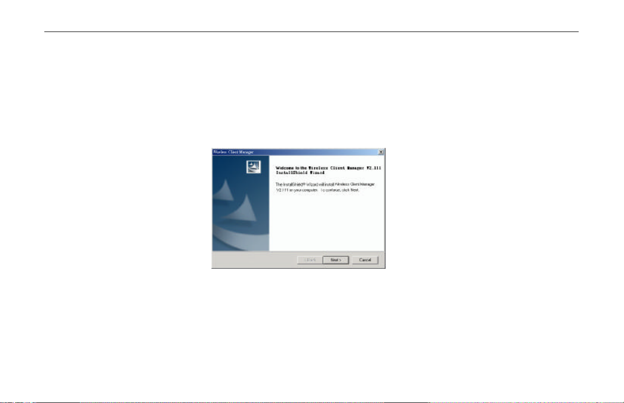
1. Locate and double-click the Wireless Client Manager installation program (setup.exe) in
2. When the Welcome screen appears, click Next.
the Utility directory of the Software Utility CD. The program will start the installation
sequence.
12
Page 19
Chapter 2 Installing the Wireless LAN Card
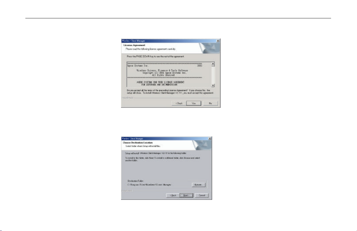
3. When the License Agreement screen appears, click Yes.
4. To install the software to the default destination folder , click Next. If you are to install
the software to a different folder, click Browse to select another folder, and then click
Next.
13
Page 20
11Mbps Wireless LAN Card User Manual
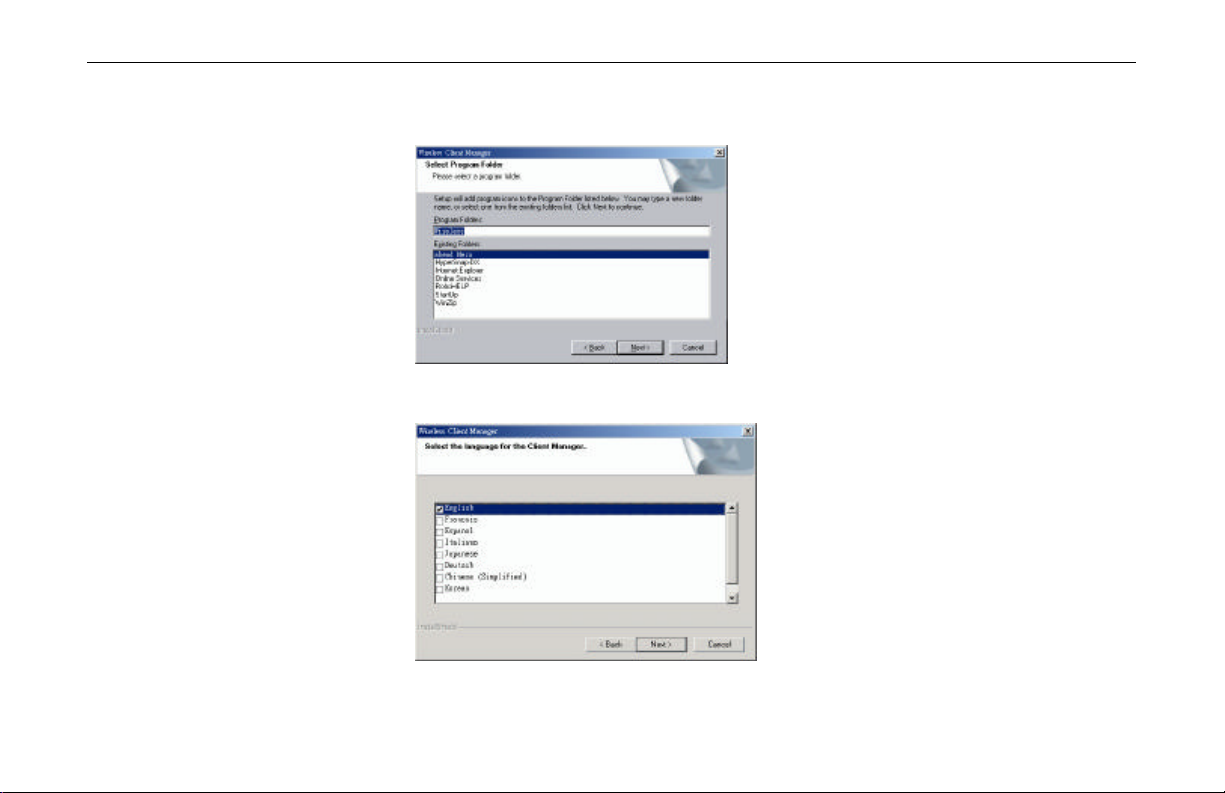
5. If required, you may type a new folder name for the program icons to be added to the
6. Select the language for the Client Manager.
Program Folder. Then click Next to continue.
14
Page 21
Chapter 2 Installing the Wireless LAN Card
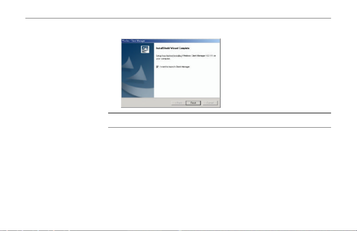
7. After Windows OS copies the setup files from the Software Utility CD, click Finish.
Note: If you need to set up the TCP/IP address or the subnet mask, refer to “Appendix C
Setting Up TCP/IP ” for details.
Now you are done with the installation procedure. Select Start > Programs > Wireless
Client Manager > Wireless Client Manager. You should be able to see the Wireless Client
Manager icon appearing on the right side of the taskbar. Proceed to following chapter to
configure or fine-tune your Wireless LAN Card settings.
15
Page 22

Page 23
Chapter 3 Wireless Client Manager
The configuration of the Wireless LAN Card is done through the Wireless Client Manager.
This utility also includes a number of tools to display current statistics and status information
pertaining to your Wireless LAN Card and to perform link test. See the appropriate subsection
as required.
Accessing the Wireless Client Manager
The Wireless Client Manager utility is launched automatically with its icon located on the
system tray. If the utility is not launched, manually start the monitor by selecting Start >
Programs > Wireless > Client Manager. You can access the Wireless Client Manager by
any of the following methods:
? Double-click the Atheros Client Utility tray icon on the system tray
17
Page 24

11Mbps Wireless LAN Card User Manual
Note to Windows XP Users
Windows XP provides built-in Wireless Zero Configuration utility for wireless
configuration and monitoring. Windows XP Wireless Zero Configuration is enabled by
default. When it is active, it will override the management of the Wireless Client Manager.
If you want to disable the Windows XP Wireless Configuration Manager and have your
device managed only by the Wireless Client Manager, please launch the Wireless Client
Manager and select File > Disable ZeroConfig.
? Right-click the tray icon and select Launch Client Manager from the context menu.
18
Page 25
Configuration for Peer-to-Peer Group
To connecting to other Wireless LAN Card equipped computers to form a Peer-to-Peer group, ,
please take out the steps below:
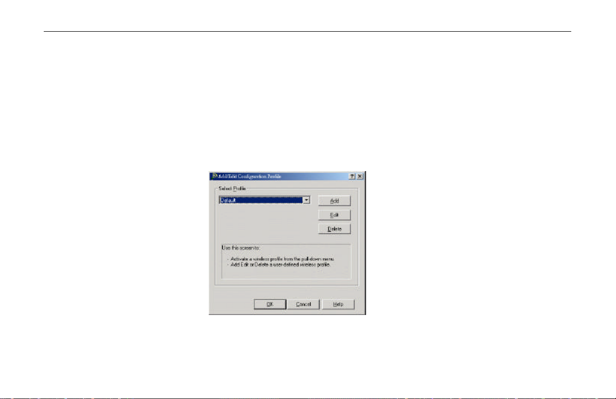
1. From Wireless Client Manager, select Actions > Add/Edit Configuration Profile.
2. Click Add to add a new profile or select one existing profile from the Select Profile
drop-down list and then click Edit to modify the settings.
Chapter 3 Wireless Client Manager
19
Page 26

11Mbps Wireless LAN Card User Manual
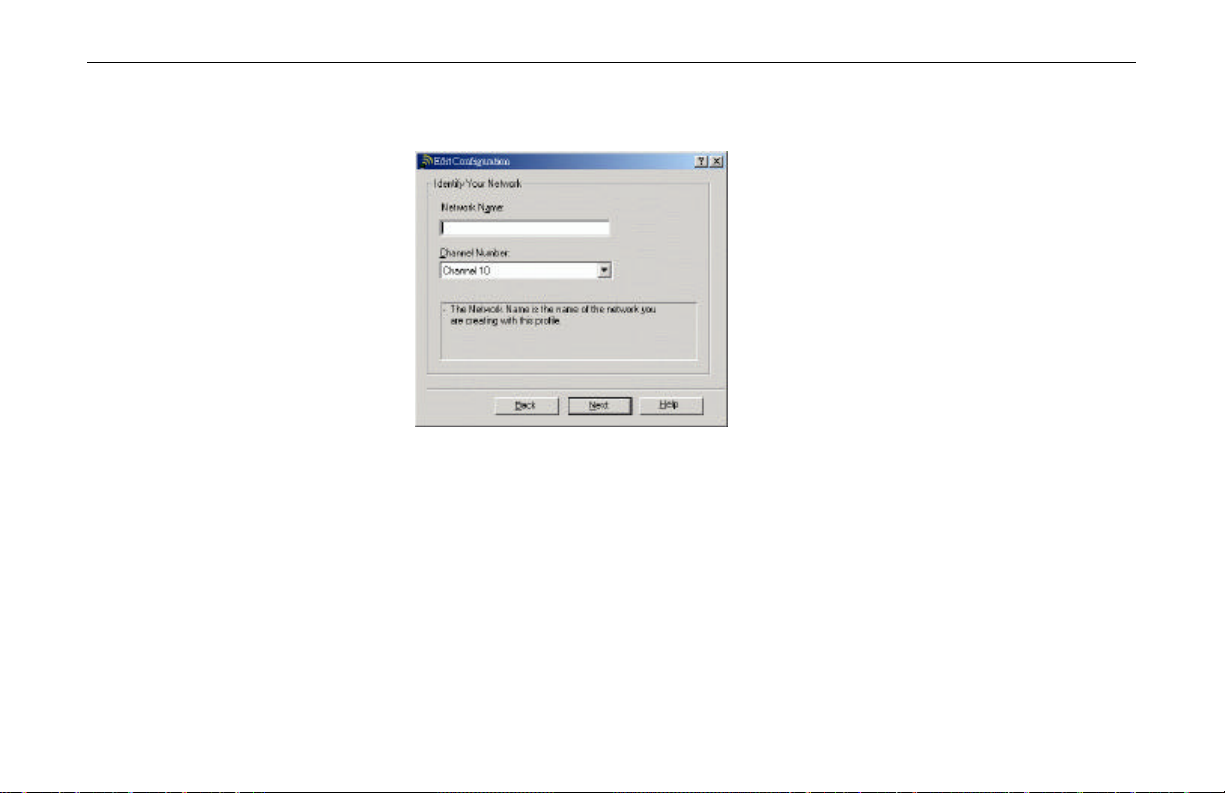
3. Enter these fields and then click Next.
4. In the Network Name field, enter a network name with a maximum limit of 32
? Profile Name: Enter a unique name to identify this configuration. A maximum of
32 characters is allowed.
? Network Type: Select Peer-to-Peer Group.
? Country: Select the country where the Wireless LAN Card is using.
characters. It is the name of the Wireless LAN group you want to participate in. The
network name for all stations in a single Peer-to-Peer Group must be the same.
20
In the Channel Number list, select the channel to be used. In a Peer-to-Peer Group, each
Wireless Client Station will automatically adopt the channel of workgroup. If your
Page 27
Chapter 3 Wireless Client Manager
computer is the first station to start the workgroup, it will use the channel selected in the
active profile.
5. If your are going to set security, check the Enable Data Security box and choose to use
Alphanumeric characters or Hexadecimal digits format to enter your WEP key. Then
enter your WEP key in the Key field.
21
Page 28
11Mbps Wireless LAN Card User Manual
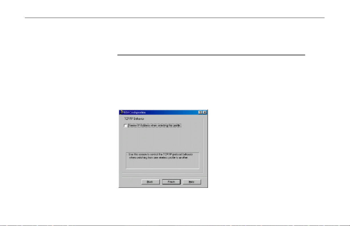
6. To renew IP address when using this profile, check the Renew IP Address when
When using Hexadecimal format, only digits 0-9 and letters a-f, A-F are allowed. Make
sure to enter the character matching the required key format and length as below:
ASCII characters Hexadecimal digits
40 bit 5 alphanumeric characters 10 hexadecimal digits
104 bit 13 alphanumeric characters 26 hexadecimal digits
selecting this profile box.
22
Page 29

Configuration for Base Station Connection
To connect to a wired/wireless network through an Access Point, please take out the steps
below:
1. From Wireless Client Manager, select Actions > Add/Edit Configuration Profile.
2. Click Add to add a new profile or select one existing profile from the Select Profile
drop-down list and then click Edit to modify the settings.
Chapter 3 Wireless Client Manager
23
Page 30
11Mbps Wireless LAN Card User Manual
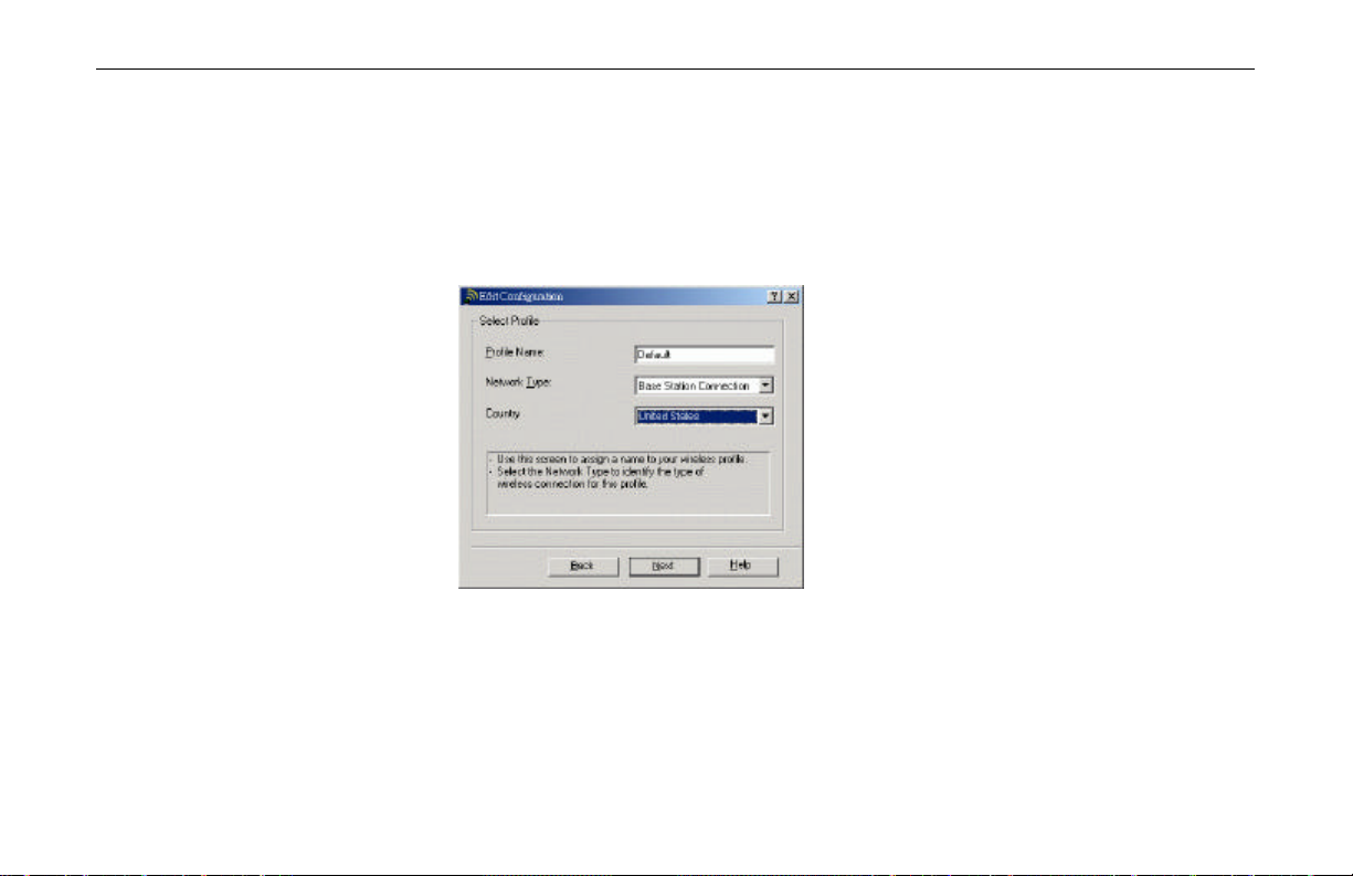
3. Enter these fields and then click Next.
4. In the Network Name field, enter a network name with a maximum limit of 32
? Profile Name: Enter a unique name to identify this configuration. A maximum of
32 characters is allowed.
? Network Type: Select Base Station Connection.
? Country: Select the country where the Wireless LAN Card is using.
characters. It is the name of the Wireless LAN group you want to participate in. The
network name for all stations in a single Base Station network must be the same.
24
Page 31
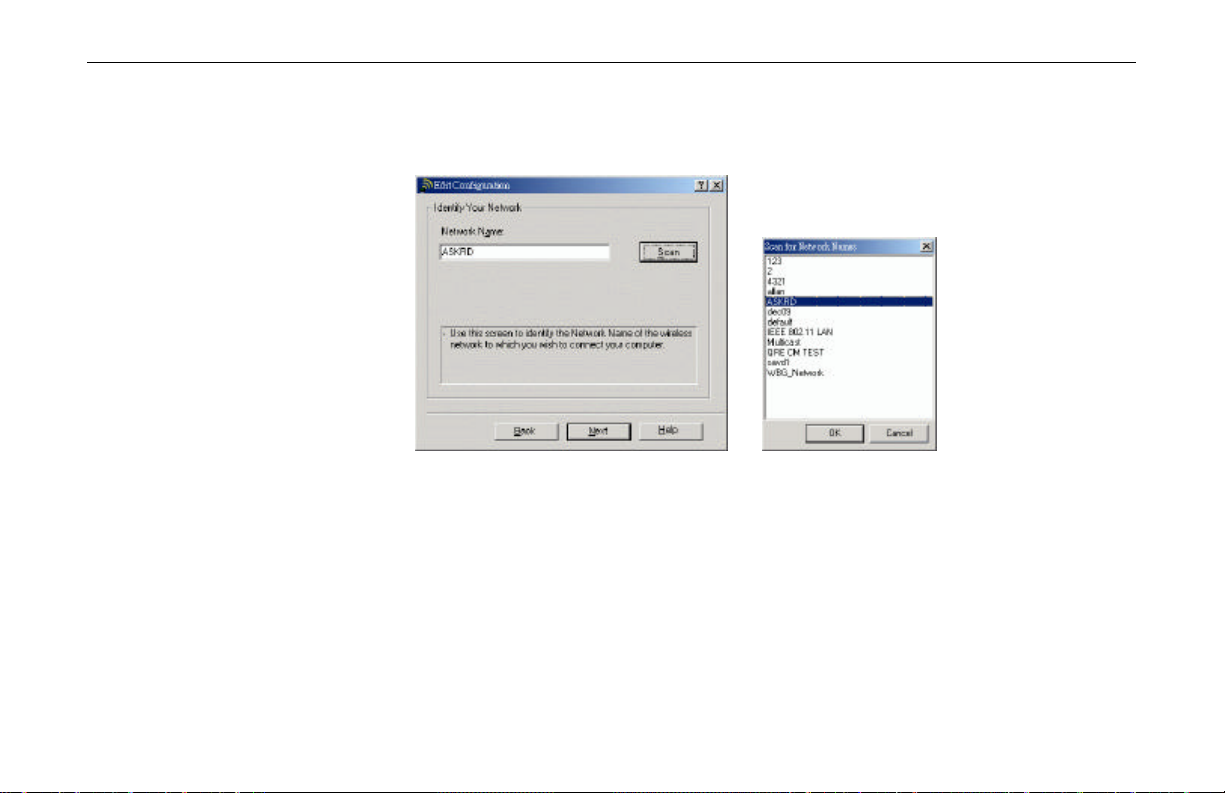
Chapter 3 Wireless Client Manager
Clicking the Scan button will pop up a separate window to display the available network
in the air. You can quickly select the desired network name by double-clicking the
network you want to connect to.
5. If your are going to set security, check the Enable Data Security box and choose to use
Alphanumeric characters or Hexadecimal digits format to enter your WEP key. Then
enter your WEP key in the Key 1 to Key 4 fields.
25
Page 32

11Mbps Wireless LAN Card User Manual
6. Select whether to enabled Power Management to adjust the power consumption behavior
When using Hexadecimal format, only digits 0-9 and letters a-f, A-F are allowed. Make
sure to enter the character matching the required key format and length as below:
ASCII characters Hexadecimal digits
40 bit 5 alphanumeric characters 10 hexadecimal digits
104 bit 13 alphanumeric characters 26 hexadecimal digits
After entering the keys, in the Encrypt Data with list, select one of the four keys to
encrypt the data you are going to transmit.
of the Wireless Client Adapter . Subject to the type of network traffic power management
may have some impact on network performance.
When enabled, the station will go to ‘sleep mode’ whenever activity is low to minimize
power consumption. At regular intervals it will wake up to verify whether there is
network traffic addressed to the wireless station.
26
Page 33

Chapter 3 Wireless Client Manager
7. To renew IP address when using this profile, check the Renew IP Address when
selecting this profile box.
27
Page 34

11Mbps Wireless LAN Card User Manual
Site Monitor
You can use the Site Monitor to display the communications quality of your computer with
multiple Base Station devices in its vicinity. The Site Monitor allows you to conduct a site
survey to:
To use the Site Monitor:
1. Launch the Site Monitor by selecting Advanced > Site Monitor from the Wireless
2. To monitor other Infrastructure networks, click the Selection tab and select a desired
? Determine the overall wireless coverage of your LAN network.
? Optimize placement of your Base Station devices, to provide seamless connectivity to
mobile stations.
? Roam throughout the wireless network environment with your Client Manager station,
you will be able to identify areas that may not have adequate coverage, or that suffer
from interference by other (wireless) equipment such as microwave ovens or photo
copiers.
Client Manager main window. The Site Monitor tab is displayed first.
Infrastructure from the Observed networks list. Then click the Scan Now button to start
the scan process. This will open the Site Monitor tab.
28
Note: The Observed networks list will only display “open” Base Stations.
Page 35

Chapter 3 Wireless Client Manager
3. The scan results are displayed in the Site Monitor tab. To tailor the display of the Site
Monitor window , refer to next section.
Figure 3-1 Site Monitor – Selection Tab
Customizing the Display of the Site Monitor
To tailor the display of the Site Monitor window, use the pull-down menus to select a
preferred set of indicators. The menu provided the following indicator options:
? MAC Address
29
Page 36

11Mbps Wireless LAN Card User Manual
The MAC address for the Wireless Network Interface of the Base Station.
? SNR
The Signal-to-Noise Ratio (SNR) is the primary diagnostic counter to diagnose wireless
performance. SNR indicates the relative strength of the received Signal Level compared
to the Local Noise Level.
In most environments, SNR is a good indicator for the quality of the radio link between
transmitter and receiver. A higher SNR value means a better quality radio link. The color
coding of the SNR-bar indicates the link quality.
? AP Names
The AP Names allows you to recognize the Base Station devices in your network more
easily, instead of identifying the units by the MAC Address of the Base Station devices.
To assign an AP names to the observed MAC address, refer to “Modifying or Adding a
Name to the Base Stations List “.
? Frequency Channel
Your wireless network uses a 2.4 GHz radio that supports multiple channels.
In a Base Station network, each Wireless Client Station will automatically adopt the same
channel.
30
In a Peer-to-Peer Group, each Wireless Client Station will automatically adopt the
channel of workgroup. If your computer is the first station to start the workgroup, it will
use the channel selected in the active profile.
Page 37

Chapter 3 Wireless Client Manager
? Signal Level
Signal Level indicates the strength of the wireless signal as received at the Wireless
Client Adapter. As the wireless system may perform quite well even when the signal
level is low, the primary indicator to diagnose the communications quality is the level of
SNR.
? Noise Level
Noise Level reflects the level of radio interference as measured at the Wireless Client
Adapter. Noise can be indicated as Local Noise or Remote Noise.
? Local Noise : The level of radio interference as measured in the vicinity of your
wireless computer.
? Remote Noise : The level of radio interference as measured in the vicinity of the
remote station (for example your 'Link Test Partner' or the Base Station).
You can sort the list of Base Station devices by the item selected in the first column, by
clicking the Sort button at the lower-left side of the Site Monitor screen. Optionally you can
click Freeze to temporarily stop the update of the counters or click Reset to reset the
diagnostic counters to zero.
31
Page 38

11Mbps Wireless LAN Card User Manual
Modifying or Adding a Name to the Base Stations List
The BS Names tab in Site Monitor window enables you to create a user-defined list of Base
Station names (the "AP Names") for the Base Station devices that are displayed in the Site
Monitor tab. This will allow you to recognize the Base Station devices in your network more
easily. You may want to complete the Base Station list due to:
Figure 3-2 Site Monitor – Site Monitor Tab
? When walking throughout the wireless networking environment, you notice that new
MAC Address values appear and you want to assign them user-defined names.
? When you spot a Base Station in the Site Monitor window that is identified as
“unknown” and you want to assign it a user-defined name.
32
Page 39

Chapter 3 Wireless Client Manager
To use the Base Station list, take out these steps:
1. Click the BS Names tab in the Site Monitor window.
2. From the list of Observed MAC Addresses, double-click the value to which you would
like to assign a user-defined name.
You will see that the value is copied to the MAC Address field on the right side of the
BS Names panel.
3. Enter the name of your choice in the BS Name field.
4. Click the button Add to table to append this name to the list of Base Station names.
If no list was available yet, the Client Manager program will create an ASCII text file
called "aplist.txt" to store the user-defined names.
5. When finished, select the tab Site Monitor to return to the panel with the dynamic
indicators.
33
Page 40

11Mbps Wireless LAN Card User Manual
Link Test
In a Peer-to-Peer Group, you can use the Link Test feature to analyze your link quality with
another peer in the same group. In Link Test Mode, your computer will actively exchange
messages with your Link Test Partner at an interval of 4 messages per second. The Link Test
mode will analyze the messages as received on your adapter and the test partner of the link to
determine:
Figure 3-3 Site Manger – BS Names Tab
34
? Radio Quality, comparing the Signal Level to the Noise Level and calculate the SNR.
Page 41

Chapter 3 Wireless Client Manager
? Throughput Efficiency, by comparing:
? the total number of Sent Messages to Received Messages, and calculate the number
of Messages Lost.
? the number of messages transmitted at the supported Transmit Rates
To start the Link Test:
1. Select Advanced > Link Test from the Wireless Client Manager main window.
2. In the Selection tab, available peers are listed and identified by their computer name and
MAC address. Select a Test Partner and click Explore Now to start the link test.
Figure 3-4 Link Test – Selection Tab
35
Page 42

11Mbps Wireless LAN Card User Manual
Viewing Liink Test Results
The Link Test results are displayed in the Test Results tab for both Link Test Partners, which
are identified by their universal MAC Address. To analyze a specific situation in more detail,
you can:
? Click the Freeze button to temporarily stop the dynamic update of the diagnostic
counters.
? Click the Reset button to reset the diagnostic counters to zero.
? Click the Advice button to assess possible impact on your network performance, or
explore suggestions to improve communications quality.
36
Figure 3-5 Link Test – Test Results Tab
Page 43

Chapter 3 Wireless Client Manager
Displaying Link Test History in Graphical Line-Chart
Use the Test History tab to display the Link Test measurement results in a graphical linechart.
It is typically used in situations where you would like to analyze communications quality
between two specific stations over a longer period of time without actively monitoring the
Test Results.
The Type of display drop-down list allow s you to display the measurement results for the
following types of history:
? SNR
? Signal Level / Noise Level
? SNR Range
? Signal Range
? Noise Range
Note: To save measurement results, set the Log Settings to save the data to a file (*.log). This
option will not save the line-chart itself, but you can import the file into a spreadsheet program
to create a line-chart tailored to your specific demands.
You can use the Time Window parameter to set the time interval for Link Test History
measurements. You can set the time interval to log measurement data at an interval of:
37
Page 44

11Mbps Wireless LAN Card User Manual
? 1 minute
? 1 hour
? 24 hours
Figure 3-6 Link Test – Test History Tab
38
Page 45

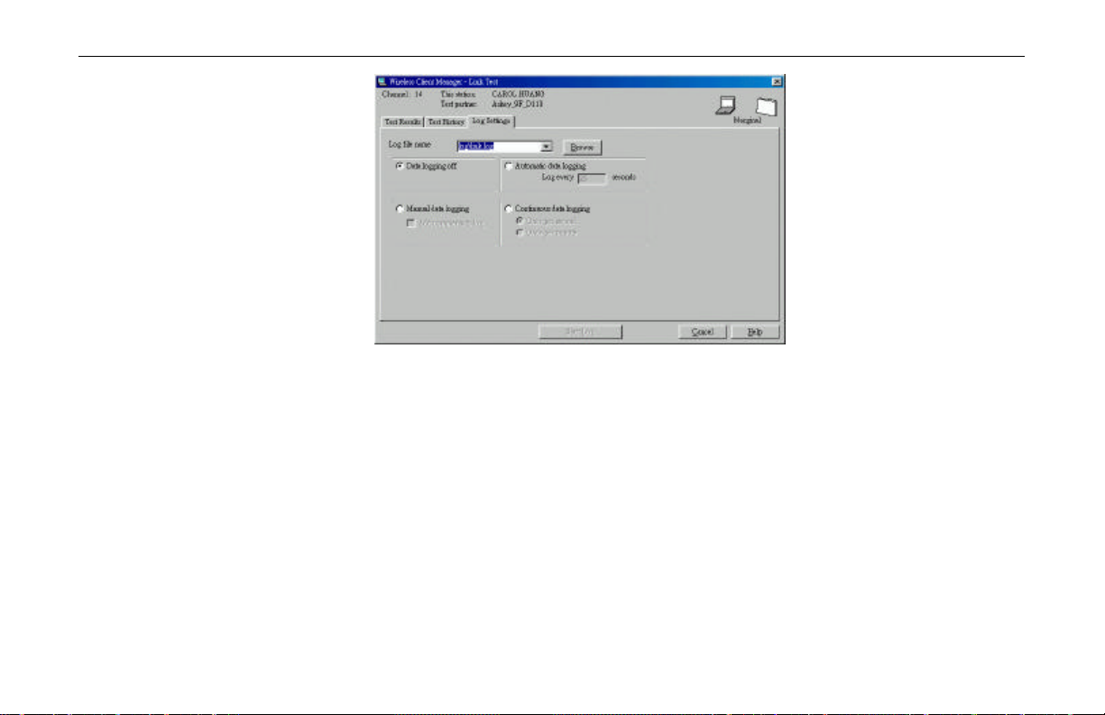
Creating Measurements Log File
The Log Settings tab in Site Monitor/Link Test window enables you to save Site
Monitor/Link Test measurement data to log file. Log files will be stored in the same directory
you selected to install the Wireless Client Manager program. The default name of the log files
are:
? log.log: For log files based on Link Test measurements.
? monitor.log: For log files based on Site Monitor measurements
The Log file name field allows you to:
? Create a new log file
In this case, in the Log filename field enter a path to store the log file followed by a new
log filename. If you do not identify a path, the program will store the file in the same
directory as the one that you selected to install your Client Manager program.
? Append to existing log file
To append data to an existing file, enter the path and the existing file name in the Log
filename field.
Chapter 3 Wireless Client Manager
39
Page 46

11Mbps Wireless LAN Card User Manual
The Log Settings tab provides a couple of logging mode choices. The number and type of
available options may differ, subject to the diagnostics mode you selected.
? Data logging off
Allows to deactivate the logging mode.
? Manual (Manual Logging Mode)
The Manual Data Logging option enables you to create log entries upon user-command.
When this option is enabled, you can manually create log file by clicking the Log Once
button. After clicking Log Once, you will be prompted to choose whether to overwrite or
append to the existing log file.
The Manual Data Logging option can be used in combination with the option Add
comments to log to add your description on specific event or location to allow easy
identification of the event or location afterwards. If Add comments to log is checked,
each time you click the Log Once button you will be prompted to enter a description as
the log information. The description will be appended to the end of the log file.
? Automatic (Automatic Every n Seconds)
Using this Log option, you can create log entry automatically at regular intervals you
specified in the Log every …seconds field. You can enter the value in the range of '0 to
999999'
40
Each time the Client Manager appends data measurements to the selected log file, it will also
reset the Test Results tab sheet.
Page 47

Chapter 3 Wireless Client Manager
? Continuous (Log History in Seconds)
This option will make a log entry each second or minute as specified. It will store history
information for a later playback analysis.
To start the logging process, you have to click the Start Log button. While logging process is
activated, you can click the Stop Log button to stop the logging process just.
Figure 3-7 Log Settings Based on Site Monitor Measurement
41
Page 48
11Mbps Wireless LAN Card User Manual
Card Diagnostics
When you suspect a malfunctioning of your Wireless Client Adapter, you can use the Card
Test information to investigate the operation of your hardware and the installed driver.
To perform a test on the status of your adapter, click the "Test Card Now" button.
Figure 3-8 Log Settings Based on Link Test Measurement
42
? If the Card Diagnostics report an error, click the Advice button for more details.
Page 49

Chapter 3 Wireless Client Manager
? In case you need to contact Technical Support click the Generate Report button to
retrieve information about your system that will help us helping you.
Figure 3-9 Diagnstic Window
43
Page 50

11Mbps Wireless LAN Card User Manual
Verifying Software Components Version
To verify the version of individual software components, select Help > Version Info from the
Wireless Client Manager main window. The screen displays the version information about the
utility, driver, card and firmware.
Figure 3-10 Version Information
44
Page 51

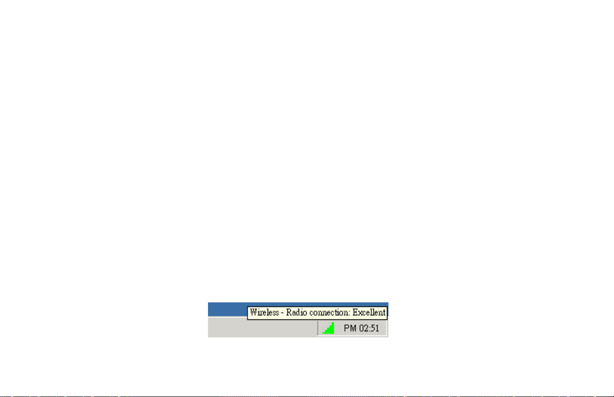
Checking Connection Status
You can check your wireless link quality via the Client Manager icon on your Windows
taskbar. The communications quality is expressed in Signal-to-Noise Ratio (SNR) to indicate
different levels of communications quality. The color coding of the SNR-bar an the
corresponding link quality are given in the table below .
Note: The SNR indicator does not work and the icon is always blank in Peer-to-Peer Group.
Indicator Color SNR Value Radio Connection Quality
Green 20 dB or higher Excellent radio connection
Green 20 dB or higher Good radio connection
Chapter 3 Wireless Client Manager
Your Wireless Client Adapter has an excellent radio
connection with the network, allowing excellent
network communication at the highest Transmit
Rate.
Your Wireless Client Adapter has a good radio
connection with the network, allowing normal
network communication.
Yellow 10 to 20 dB Marginal radio connection
The radio signal is weak. Your Wireless Client
Adapter has a marginal radio connection with the
45
Page 52

11Mbps Wireless LAN Card User Manual
Indicator Color SNR Value Radio Connection Quality
network. This connection does allow network
communication, but you might observe a
degradation of the network response times due to
(re)transmissions at a lower Transmit Rate. Move
closer to the Wireless LAN Base Station.
Red 0 to 10 dB Poor radio connection or no radio connection.
The radio signal is very weak, you are Out of
Range. Save your files and move closer to the
Wireless LAN Base Station.
Red 0 dB No network connection
Looking for initial connection or you have moved
out of range of the network.
Blank N/A No Connectio n
The Wireless Client Manager program could not
detect the presence of the Wireless Client Adapter
or your network interface has been set to operate in
Peer-to-Peer Group mode.
46
Page 53
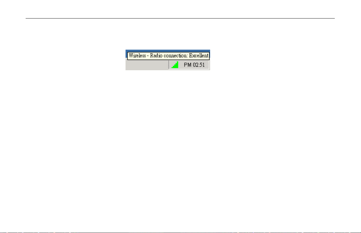
While connected in Infrastructure mode, you can place your cursor over the icon to see the
pop-up text that gives link quality information about the current wireless connection.
PART 2. Configuration Utility for Windows XP
Windows XP provides built-in Wireless Zero Configuration utility for wireless
configuration and monitoring. You can choose to configure your wireless network via either
the Wireless Client Manager as described in preceding section, or to use the Windows XP
Wireless Zero Configuration utility.
This section only provides the essential instructions on using Windows XP wireless utility to
get your wireless network established. For more information please refer to Windows XP online help.
Chapter 3 Wireless Client Manager
47
Page 54

11Mbps Wireless LAN Card User Manual
Connecting to an Access Point or Wireless LAN Card
Windows XP Wireless Zero Configuration utility can be quickly accessed via the network
connection icon on the system tray. If your computer is not connected to any Access
Point/Wireless LAN Card yet, the icon should appear as below:
To connect to an existing Access Point/Wireless LAN Card (Peer-to-Peer Group), do the
following:
1. Double-click the network connection icon on the system tray.
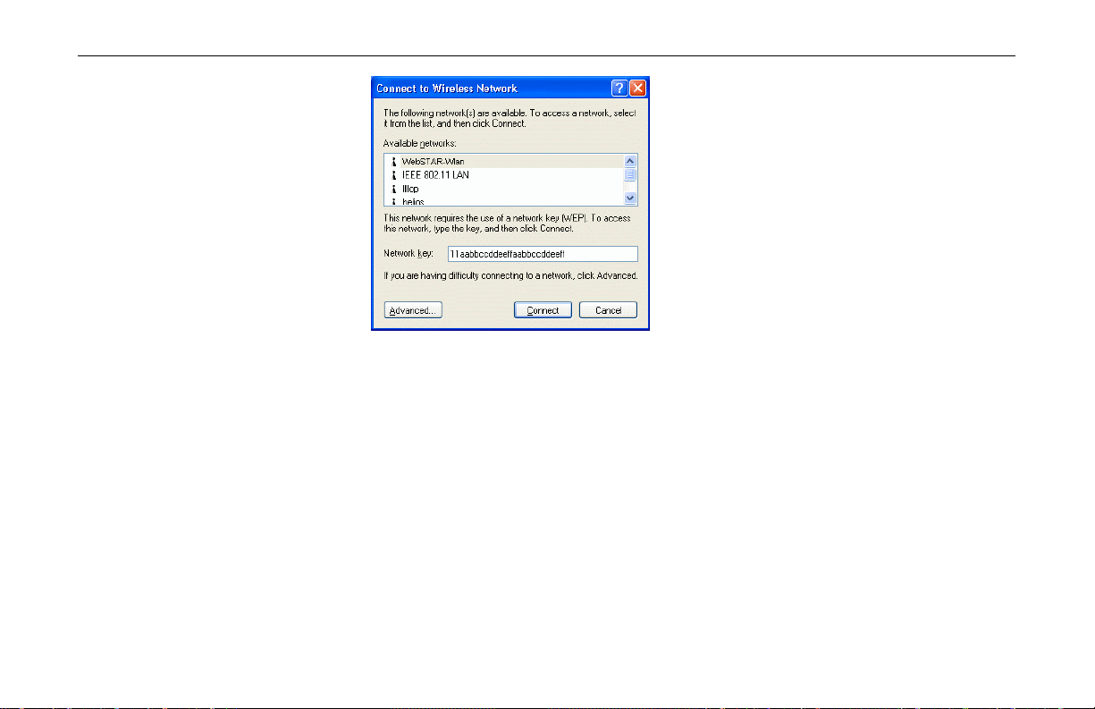
2. When the Connect to Wireless Network window pops up, you will see all the Access
Points or Wireless LAN Cards (Peer-to-Peer Group) that are available in the air. Select
the wireless network you want to connect to.
48
Page 55
Chapter 3 Wireless Client Manager
Figure 3- 11 Windows XP Configuration Utility-Connect to Wireless Network
3. If the target Access Point/Wireless LAN Card (Peer-to-Peer Group) has been set with
WEP key, you must enter the same WEP key in the Network key field. Otherwise, leave
it blank.
4. Click Connect, then you will join the target network and this dialog window will
disappear. When your wireless connection is established, the connection icon appears as
below:
49
Page 56

11Mbps Wireless LAN Card User Manual
Note: If the wireless connection can’t be established, double-click the connection icon and
then click Properties . Go to Authentication tab first to make sure that you use the correct
authentication type for the Wireless LAN Card. For more information, refer to
“Authentication” on page 56.
Viewing Wireless Connection Status
After you successfully connect to the Access Point or Wireless LAN Card (Peer-to-Peer
Group), double-click the icon in the system tray again. This will open the Wireless Network
Connection Status window where you can see the general data of the Wireless LAN Card,
such as Status, Duration, Speed, Signal Strength, etc.
50
Page 57

Chapter 3 Wireless Client Manager
Figure 3- 12 Windows XP- Connection Status
Configuring Your Wireless Properties
To configure your wireless properties, open the Wireless Network Connection Status
window as described above, and then click the Properties button. This will open the Wireless
Network Connection Properties window which allows you to configure more detailed items
of the Wireless LAN Card. The following describes each tab of the properties window to help
you do more settings of the Wireless LAN Card.
51
Page 58
11Mbps Wireless LAN Card User Manual
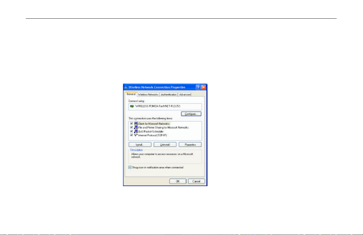
General
This tab allows you to specify the network methods to be used with your Wireless LAN
PCMCIA Card. The network policy depends on your wireless network. For TCP/IP protocol,
you should configure its properties as instructed by your network administrator. For more
information on TCP/IP setting, please refer to “Appendix C Setting Up TCP/IP” on page
75.
52
Figure 3- 13 Windows XP Connection Properties -General
Page 59
Chapter 3 Wireless Client Manager
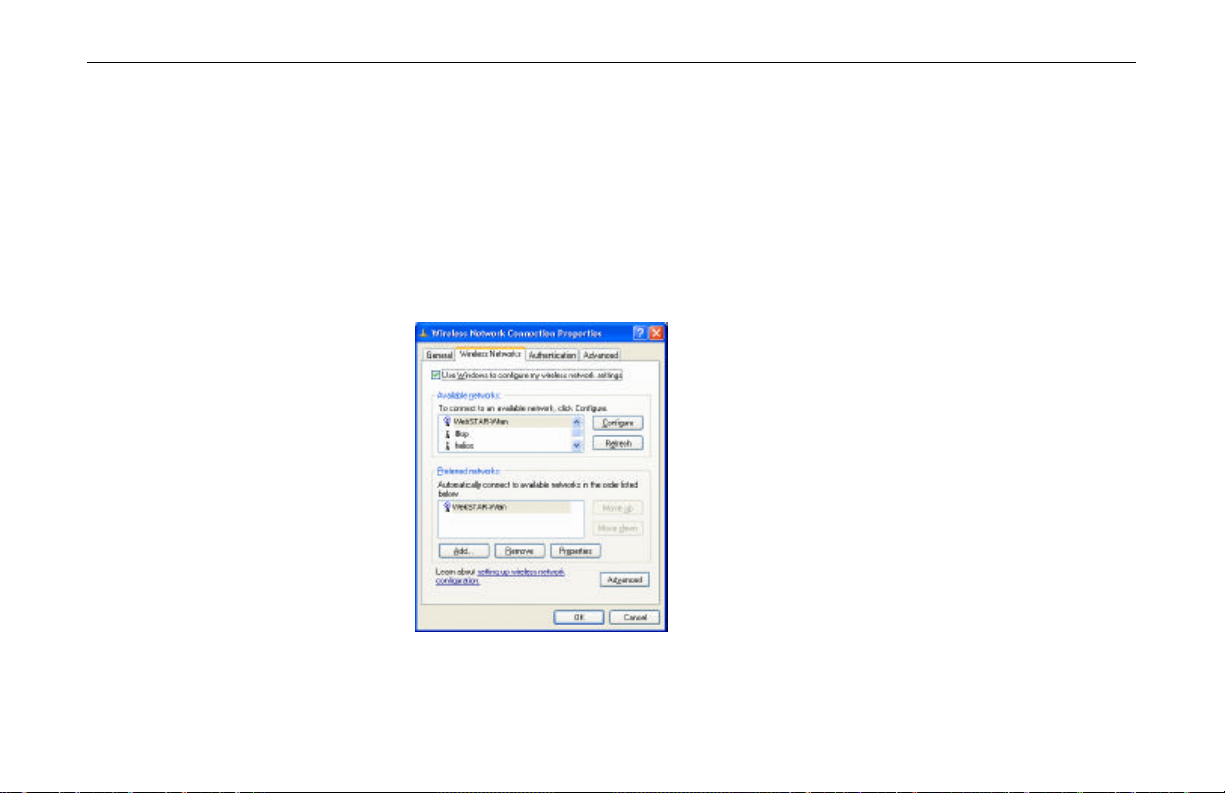
Wireless Networks
This tab contains two sections: Available networks and Preferred networks described as
below.
Under Available networks section, you can also see all the Access Points and Wireless LAN
Cards (Peer-to-Peer Group) available in the air. Clicking Refresh will update the list of
Access Points and Wireless LAN Cards (Peer-to-Peer Group).
Figure 3- 14 Windows XP Connection Properties-Wireless Networks
53
Page 60

11Mbps Wireless LAN Card User Manual
Under Preferred networks section, you can add any wireless networks that you wish to
connect to. To do this, just click Add to add more Access Points or Wireless LAN Cards
(Peer-to-Peer Group) to the list.
After you click the Add button, the Wireless Network Properties window pops up. Type
your network name (SSID) and, if needed, the wireless network WEP settings. Once the
Access Point or Wireless LAN Card (Peer-to-Peer Group) that you want to connect to has
been set with WEP key, you must type the same WEP key as the Access Point’s or Wireless
LAN Card’s.
54
Figure 3- 15 Windows XP-Add Preferred Networks
Page 61

Chapter 3 Wireless Client Manager
After you add several profiles into Preferred networks, you can change the order in which
connection attempts to preferred networks are made. Just select the target wireless network
and click Move up or Move down to move it to a desired position.
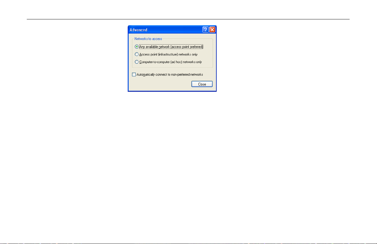
To Access Certain Wireless Network Only
If you just want to access certain wireless network type, click the Advanced button on the
Wireless Networks tab (Figure 3-12) to open the Advanced window. You can choose to
connect to the following networks:
? Any available network ( access point preferred)
? Access point (infrastructure)
? Computer-to-computer (Peer-to-Peer Group)
The default network type is Any available network ( access point preferred). In this
network type, your device will connect to any Access Points or Wireless LAN Cards (Peer-toPeer Group) available in the air but Access Point always demands higher connection attempt
priority.
Once you finish the advanced setting, your wireless station will then connect to your desired
network and the connected network will be listed under Available networks.
55
Page 62
11Mbps Wireless LAN Card User Manual
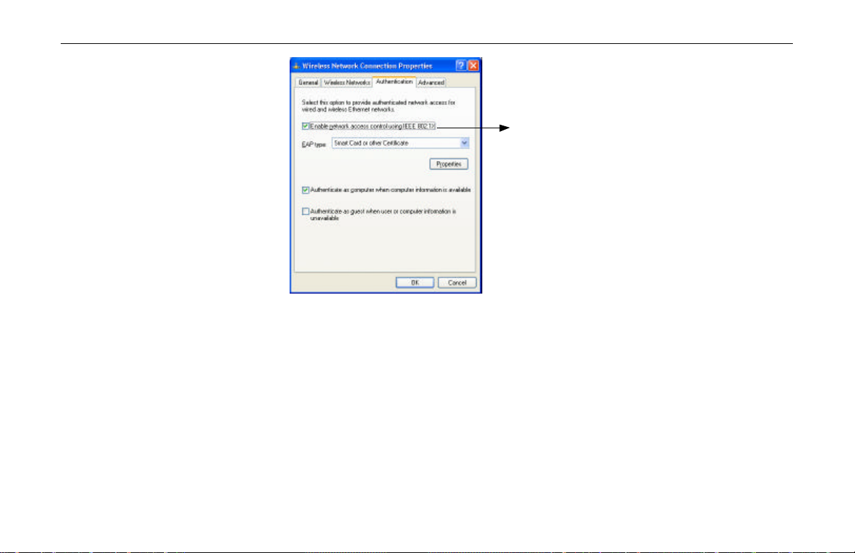
Authentication
This tab allows you to configure the authentication settings of your Wireless LAN Card. The
most important setting for the Wireless LAN Card is to disable Enable network access
control using IEEE802.1X to ensure successful connection between the Wireless LAN Cards
and Access Points or other Wireless LAN Card (Peer-to-Peer Group). You must disable this
function for any reason. Otherwise, there may be some problems happening during connection.
For other settings, we recommend you keep the default settings to minimize the problems
during connection.
Figure 3- 16 Windows XP Configuration Utility-Set up Network to Aceess
56
Page 63
Chapter 3 Wireless Client Manager
Make sure to clear the
Enable
network access control using
IEEE802.1X check box to ensure
successful connection.
Figure 3- 17 Windows XP Connection Properties -Authentication
57
Page 64

Page 65

Chapter 4 Uninstalling the Wireless LAN Card
Should you need to uninstall the Wireless LAN Card and application software for any reason,,
you should uninstall the associated software and then remove the hardware from your
computer. Please proceed as follows.
Part 1: Uninstalling the Wireless Client Manager
1. Double-click the Add/Remove Programs (or Add or Remove Programs for Windows
XP) icon under Control Panel.
2. Highlight Wireless Client Manager V2.111 from the list and then click Add/Remove
or Change/Remove.
59
Page 66

11Mbps Wireless LAN Card User Manual
3. When confirmation message appears, click OK to remove the components.
4. You will find that the Wireless Client Manager V2.111 has been removed. The
Part 2: Removing the Wireless LAN Card
The Wireless LAN Card complies with the PCMCIA standard that allows devices to be
inserted into and removed from the computer’s PCMCIA slot when the computer is power on.
To permanently remove the wireless adapter, please follow the standard Windows procedure
for removing a PCMCIA device from your computer.
software uninstallation is complete.
60
Page 67

Chapter 4 Uninstalling the Wireless LAN Card
1. On the system tray, click the PCMCIA icon, and then click Stop Wireless PC Card
0110.
2. Launch the Device Manager as below:
? For Windows 98/Me: Under Control Panel, click System > Device Manger.
? For Windows 2000/XP: Under Control Panel, click System > Hardware >
Device Manager.
3. In Device Manager window, double-click Network adapters to display the adapter
Wireless PC Card Model 0110.
4. Right-click the Wireless PC Card Model 0110 and select Uninstall from the context
menu.
5. When warning message appears, click Yes. Now you can safely remove the wireless
adapter from the PCMCIA slot.
61
Page 68

Page 69

Chapter 5 Updating the Device Driver
Periodically, you may need to upgrade the Wireless LAN Card’s driver when a newer version
is available. Check our website for information about the latest driver upgrades. When you
have finished the download procedure, please follow as below to update the device driver.
1. Uninstall the Wireless LAN Card as described in Chapter 4. Follow the steps to remove
the Wireless LAN Card and then uninstall the software.
2. Install the new driver you have downloaded. Refer to Chapter 2 for detailed instructions.
Once you finish installing the new driver, the updating is complete.
63
Page 70

11Mbps Wireless LAN Card User Manual
64
Page 71

Chapter 6 Troubleshooting
Radio Interference
You may be able to eliminate any interference by trying the following:
? Reseat the Wireless LAN Card.
? Increase the distance between the wireless computers and the device causing the
radio interference.
? Plug the computer equipped with the Wireless LAN Card into an outlet on a
different branch circuit from that used by the affecting device.
? Consult the dealer or an experienced radio technician for help.
? Keep the computer with the Wireless LAN Card away from the microwave oven
and large metal objects.
65
Page 72

11Mbps Wireless LAN Card User Manual
Card Not Detected
If the Wireless LAN Card is not detected by Windows, try the following:
Cannot Connect to Another Wireless LAN Card
If you cannot make a connection to another Wireless LAN Card from your computer, it could
be due to one of the following reasons:
? Make sure the Wireless LAN Card is properly inserted in the PCMCIA slot.
? Make sure the PCMCIA slot in your computer is working.
? Contact your dealer for additional testing if there is a hardware problem with the
Wireless LAN Card.
? Incorrect SSID. Make sure the SSID is the same for all computers that have a
Wireless LAN Card.
? Changes are not being recognized by your computer. Rest art your computer.
? If in Peer-to-Peer Group, make sure the Log on to Windows NT domain check
box is not selected in the Client for Microsoft Networks Properties dialog box in
the Network Configuration tab.
? Incorrect IP Address or Subnet Mask . Check these settings in the TCP/IP
Properties dialog box in the Network Configuration tab.
66
Page 73

Poor Link Quality
If the Link Quality display stays in the Poor range, it could be due to one of the following
reasons:
? Radio interference.
? Distance between Wireless LAN Card and Access Point is too far. Decrease the
distance between the Wireless LAN Card and Access Point (or another card).
Cannot Connect to Access Point
If you cannot make a connection to the Access Point, it could be due to one of the following
reasons:
? Make sure the Wireless LAN Card and Access Point have no physical connection
problems.
? Make sure the SSID for the Wireless LAN Card is the same as the Access Point.
? Make sure the privacy type is the same as that of Access Point. Also, make sure the
Default Key is the same for both computers.
Chapter 6 Troubleshooting
67
Page 74

11Mbps Wireless LAN Card User Manual
68
Page 75

Appendix A Limited Warranty
Wireless LAN Hardware
The seller warrants to the end user (“Customer”) that this hardware product will be free from
defects in workmanship and materials, under normal use and service, for 1 year from the date
of purchase from the seller or its authorized reseller. The seller’s sole obligation under this
express warranty shall be, at the seller’s option and expense, to repair the defective product or
part, deliver to Customer an equivalent product or part to replace the defective item, or if
neither of the two foregoing options is reasonably available, The seller may, in its sole
discretion, refund to the Customer the purchase price paid for the defective product. All
products that are replaced will become the property of the seller. Replacement products may
be new or reconditioned.
69
Page 76

11Mbps Wireless LAN Card User Manual
Wireless LAN Software
The seller warrants to Customer that each software program licensed from it , except as noted
below, will perform in substantial conformance to its program specifications, for a period of 1
year from the date of purchase from the seller or its authorized reseller. The seller warrants the
media containing software against failure during the warranty period. No updates are provided.
The seller’s sole obligation under this express warranty shall be, at the seller’s option and
expense, to refund the purchase price paid by Customer for any defective software product, or
to replace any defective media with software which substantially conforms to applicable seller
published specifications. Customer assumes responsibility for the selection of the appropriate
application programs and associated reference materials. The seller makes no warranty or
representation that its software products will meet Customer’s requirements or work in
combination with any hardware or software applications products provided by third parties,
that the operation of the software products will be uninterrupted or error free, or that all
defects in the software products will be corrected. For any third party products listed in the
seller software product documentation or specifications as being compatible, the seller will
make reasonable efforts to provide compatibility, except where the non-compatibility is
caused by a defect in the third party’s product or from use of the software product not in
accordance with the seller’s published specifications or user manual.
70
Page 77

Appendix B Regulatory Compliance
FCC Part 15 Declaration of Conformity (DoC)
The following equipment:
Product Name: Wireless LAN Card
is herewith confirmed to comply with the requirements of FCC Part 15 rules. The operation is
subject to the following two conditions:
1. This device may not cause harmful interference, and
2. This device must accept any interference received, including interference that may cause
undesired operation.
71
Page 78

11Mbps Wireless LAN Card User Manual
FCC Rules and Regulations - Part 15
Warning: This device has been tested and found to comply with the limits for a Class B digital device
pursuant to Part 15 of the Federal Communications Commissions Rules and Regulation. These limits are
designed to provide reasonable protection against harmful interference when the equipment is operated
in a commercial environment. This equipment generates, uses, and can radiate radio frequency energy
and, if not installed and used in accordance with the instruction manual, may cause harmful interference
to radio communications.
However, there is no guarantee that interference will not occur in a particular installation. If this
equipment does cause harmful interference to radio or television reception, which can be determined by
turning the equipment off and on, the user is encouraged to try and correct the interference by one or
more of the following measures:
Relocate your WLAN equipped laptop computer.
Increase the separation between the WLAN equipped laptop computer and other electronics.
Connect the WLAN equipped laptop computer into an outlet on a circuit different from that
of other electronics.
Consult the dealer or an experienced radio/TV technician for help.
72
Page 79

FCC Radiation Exposure Statement
FCC Caution: Any changes or modifications not expressly approved by the party responsible for compliance could
void the user's authority to operate this equipment.
This transmitter must not be co-located or operating in conjunction with any other antenna or transmitter.
This device complies with FCC RF exposure limits set forth for an uncontrolled environment, under 47 CFR
2.1093 paragraph (d)(2).
This equipment complies with FCC radiation exposure limits set forth for an uncontrolled
environment.
Appendix B Regulatory Compliance
73
Page 80

11Mbps Wireless LAN Card User Manual
74
Page 81
Appendix C Setting Up TCP/IP
This section contains instructions for configuring the TCP/IP protocol of the Wireless LAN
PCMCIA Card. The IP address policy depends on your wireless network. You should
configure your TCP/IP protocol as instructed by your network administrator.
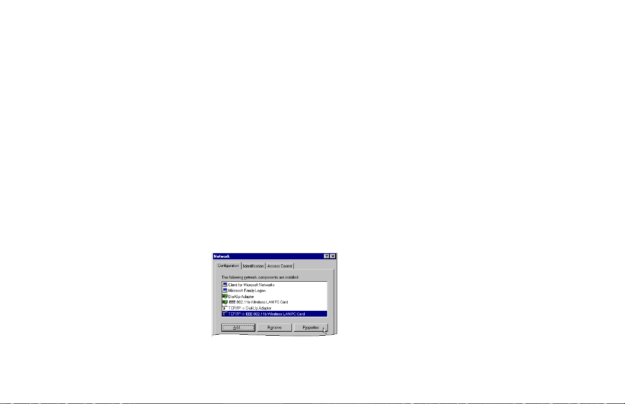
1. On the taskbar , select Start > Settings > Control Panel, double-click the Network icon.
2. Click the Configuration tab of the Network dialog box.
3. In the network components list, select the TCP/IP protocol of your Wireless LAN Card,
e.g., TCP/IP ->IEEE 802.11b Wireless LAN PC Card, and then click Properties .
75
Page 82

11Mbps Wireless LAN Card User Manual
wireless LAN installation,
For correct IP address
information for your
contact your network
administrator.
For more information on IP
addresses, see the Network
Working Group
Specification RFC 1918 on
the Internet.
4. On the IP Address tab, choose one of the methods as required:
Option A: Click Specify an IP address.
In the IP Address box, enter a valid four-component IP address, either a public or
private one as required. If private IP address is used, the following three blocks of IP
addresses are available for private network s:
10. 0 . 0. 0 — 10.255.255.255
172. 16. 0. 0 — 172. 31.255.255
192.168. 0. 0 — 192.168.255.255
In the Subnet Mask box, enter a valid four-component IP address.
76
Page 83

Appendix C Setting Up TCP/IP
77
Page 84

11Mbps Wireless LAN Card User Manual
5. Click OK to return to Network dialog box and click OK again to finish configuration. If
Option B: Select Obtain an IP address automatically.
An IP address will be automatically assigned to your computer.
your TCP/IP properties have been modified, you will be prompted to restart your
computer. Click Yes to have new settings take effect.
78
Page 85

Appendix C Setting Up TCP/IP
79
Page 86

Page 87

Glossary
10BaseT An IEEE standard (802.3) for operating 10 Mbps Ethernet networks (LAN s) with twisted pair
cabling and a wiring hub.
Access Point An internetworking device that seamlessly connects wired and wireless networks. Access Points
combined with a distributed system support the creation of multiple radio cells that enable
roaming throughout a facility.
Peer-to-Peer
Group
Channel A medium used to pass protocol data units that can be used simultaneously in the same volume
Encapsulated An Ethernet address mode that treats the entire Ethernet packet as a whole and places it inside
A network composed solely of stations within mutual communication range of each other (no
Access Point connected).
BSS Basic Service Set. A set of stations controlled by a single coordination function.
of space by other channels of the same physical layer, with an acceptably low frame error ratio
due to mutual interference.
an 802.11 frame along with a new header.
81
Page 88

11Mbps Wireless LAN Card User Manual
ESS Extended Service Set. A set of one or more interconnected Basic Service Sets (BSSs) and
integrated Local Area Networks (LANs) can be configured as an Extended Service Set.
Ethernet The most widely used medium access method, which is defined by the IEEE 802.3 standard.
Ethernet is normally a shared media LAN; i.e., all the devices on the network segment share
total bandwidth. Ethernet networks operate at 10Mbps using CSMA/CD to run over 10BaseT
cables.
Gateway A network component that acts as an entrance to another network.
IEEE 802.11 The IEEE 802.xx is a set of specifications for LANs from the Institute of Electrical and
Electronic Engineers (IEEE). Most wired networks conform to 802.3, the specification for
CSMA/CD-based Ethernet networks or 802.5, the specification for token ring networks. 802.11
defines the standard for wireless LANs encompassing three incompatible (non-interoperable)
technologies: Frequency Hopping Spread Spectrum (FHSS), Direct Sequence Spread Spectrum
(DSSS), and Infrared. IEEE standards ensure interoperability between systems of the same type.
Infrastructure A wireless network centered about an Access Point. In this environment, the Access Point not
only provides communication with the wired network but also mediates wireless network traffic
in the immediate neighborhood.
IP Internet Protocol. The standard protocol within TCP/IP that defines the basic unit of
information passed across an Internet connection by breaking down data messages into packets,
routing and transporting the packets over network connections, then reassembling the packets at
their destination. IP corresponds to the network layer in the ISO/OSI model.
82
Page 89

Glossary
IP Address An IP address is a 32-bit number that identifies each sender or receiver of information sent
across the Internet. An IP address has two parts: the identifier of a particular network on the
Internet and an identifier of the particular device (which can be a server or a workstation) within
that network.
ISP Internet Service Provider. An organization that provides access to the Internet. Small ISPs
provide service via modem and ISDN while the larger ones also offer private line hookups (T1,
fractional T1, etc.).
LAN Local Area Networ k. A communications network that serves users within a defined
geographical area. The benefits include the sharing of Internet access, files, and equipment, such
as printers and storage devices. Special network cabling (10BaseT) is often used to connect the
PCs together.
NAT Network Address Translation. The translation of an Internet Protocol address (IP address) used
within one network to a different IP address known within another network. One network is
designated the internal network and the other is the external. The internal network then appears
as one entity to the outside world.
83
Page 90

11Mbps Wireless LAN Card User Manual
Radio
Frequency
RF, Terms: GHz, MHz, Hz —The international unit for measuring frequency is Hertz (Hz),
equivalent to the older unit of cycles per second. One megahertz (MHz) is one Million-Hertz.
One giga hertz (GHz) is one Billion-Hertz. The standard U.S. electrical power frequency is 60
Hz, the AM broadcast radio frequency band is 0.55–1.6 MHz, the FM broadcast radio frequency
band is 88–108 MHz, and wireless 802.11 LANs operate at 2.4GHz.
SSID Service Set ID. A group name shared by every member of a wireless network. Only client PCs
with the same SSID are allowed to establish a connection.
Subnet Mask A value that defines whether your computer communicates only within your LAN or
communicates outside of your LAN, where it is routed out to the rest of the Internet. A Subnet
Mask that has the same first three components (for example, 255.255.255.0) is the routing
pattern for a Class C address.
TCP Transmission Control Protocol. The standard transport level protocol that provides the full
duplex, stream service on which many applications’ protocols depend. TCP allows a process on
one machine to send a stream of data to a process on another. Software implementing TCP
usually resides in the operating system and uses the IP to transmit information across the
network.
WEP Wired Equivalent Privac y. The optional cryptographic confidentiality algorithm specified by
802.11. The algorithm is being used to provide data confidentiality that is subjectively
equivalent to the confidentiality of a wired LAN medium that does not employ cryptographic
techniques to enhance privacy..
84
Page 91

85
 Loading...