

Page 1

Access Point
.........................................................................................
User Guide
Page 2

Page 3

Table of Contents
Section 1
Introduction ..........................................................................................1-1
1.1 Package Contents ....................................................................................1-1
1.2 System Requirements ..............................................................................1-1
1.3 AT76C510 Features .................................................................................1-1
1.4 Firmware Features ...................................................................................1-2
1.5 Bridging Functions ...................................................................................1-2
1.6 Management ............................................................................................1-2
1.7 Roaming ...................................................................................................1-2
1.8 Operation Modes .....................................................................................1-2
1.9 Network Interface .....................................................................................1-2
1.10 Radio Interface .........................................................................................1-2
Section 2
The AP Development Board.................................................................2-1
Section 3
Setting the IP Address of the Access Point .........................................3-1
3.1 Using the Ethernet Port ............................................................................3-1
3.2 Using the USB Port ..................................................................................3-2
Section 4
Access Point Configuration ..................................................................4-1
4.1 Using the Ethernet Port ............................................................................4-1
4.1.1 How to Install the SNMP Manager ....................................................4-1
4.1.2 Using the SNMP Manager .................................................................4-1
4.1.3 How to Uninstall the SNMP Manager ..............................................4-10
4.2 Using the USB Port ................................................................................4-10
Section 5
Access Point Firmware Upgrade ........................... ..... .... ..... ................5-1
5.1 Using the Ethernet Port ............................................................................5-1
5.1.1 How to Install the TFTP Client ...........................................................5-1
5.1.2 Using the TFTP Client .......................................................................5-1
5.1.3 How to Uninstall the TFTP Client ......................................................5-2
5.2 Using the USB Port ..................................................................................5-2
User Guide
Page 4

Page 5

Section 1
Introduction
The AP (IEEE 802.11 HR, 11 Mbps WLAN Access Point) is a long-range, high
performance LAN product, which provides Access Point services to a 2,4 GHz RF network and bridges to an Ethernet backbone. The design of this product is based on
AT76C510 (bridge-on-a-chip) module, a highly integrated ASIC desi gned to combine
legacy LANs with wireless LANs. AT76C510 performs all the necessary inter-networking and bridging functions. It receives data from both networks, stores them locally for
further processing, inst alls and maintains connections and transmits the pac kets to the
proper destination. Furthermore, AT76C510 interfaces three more modules, the Ethernet PHY, the wireless PHY and the RAM modules, for allowing compact system
implementation and flexibility for supporting almost all the possible physical interfaces.
This document describes the steps required for the initial set up of the AP IP address,
the AP configuration, and the firmware upgrade procedure. The description includes the
implementation of the above steps through both Ethernet and USB.
1.1 Package Contents
1.2 System Requirements
1.3 AT76C510 Features
Please make sure that you received the following with your AT76C510-Development Kit:
•One Bridge Access Point board
•One MACless Radio card
•User Guide
•Firmware, Drivers, and Software Tools CD
For configuration through USB:
•Operating System: MS Windows
•Desktop PC or notebook PC with USB port
•USB cable
•4.5-5V (regulated)-1Amp power supply cable
For configuration through Ethernet:
•Operating System: MS Windows
•Desktop PC or notebook PC connected on a LAN
•Ethernet cable
•4.5-5V (regulated)-1Amp power supply cable
Among the features of the AT76C510 bridge-on-a-chip are the following:
®
98
®
98, Windows® 2000, Windows® NT 4.0
1-1
Rev. 1932A-9/28/00
Page 6

Introduction
–Glueless connection to Intersil PRISMI, PRISMII Direct Sequence Spread Spectrum
(DSSS) radio chip set. Able to communicate also with other DSSS radios
–Supports 11, 5.5, 2 and 1 Mbps rates
–WEP encryption/decryption is accomplished on the fly
–Ethernet MAC supports MII interface and 10/100Mbit speeds
–Hardware modules for Packet Filtering and statistics gathering
–Glueless SRAM, Flash interface for data buffering and program storage, supporting
up to 16 MB of memory
–Integrated 2 x 6K x 32 bit internal SRAM modules for fast 32-bit program execution
and temporary storage of data
–Supports 3V supply
–128-pin PQFP, TQFP
–JTAG Boundary Scan (IEEE 1149.1) test access port for board-level production test
1.4 Firmware Features
1.5 Bridging Functions
1.6 Management
The IEEE 802.11 HR firmware implementation for the supports:
–Distributed Coordination Function
CSMA/CA
Backoff Procedure
NAV Management
ACK Procedure
Retransmission of unacknowledged frames
–RTS/CTS Handshake
–Duplicate Detection and Recovery
–Beacon Generation
–Probe Response
–Fragmentation and Reassembly
–Wired Equivalent Privacy Algorithm (WEP 40 bits)
–Authentication Algorithm (Open System, Shared Key)
–Short Preamble
The following bridging functions are supported:
–Automatic Learning Process
–Filtering Database
–Forwarding Process
–Protocol Filtering
–IP Filtering
For Bridge Management supports:
–SNMP (MIB, traps)
–TFTP (firmware download)
–USB (DFU-configuration)
1.7 Roaming
1.8 Operation Modes
1.9 Network Interface
1.10 Radio Interface
1-2
Roaming functions supported:
–Among APs on the same subnet
Operation Modes supported:
–Access Point
AP supports 10/100 Mbps network interface.
As far as the radio interface is concerned, AP supports:
–Antenna Diversity
–Specific Antenna Tx/Rx
Page 7
Section 2
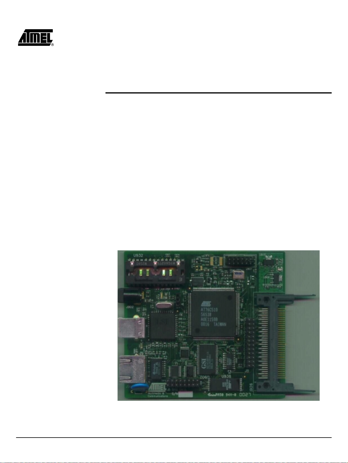
The AP Development Board
Figure 2-1 shows the Access Point development board. The basic features of this board are outlined below:
•Interfaces directly to 10/100 IEEE 802.3 Ethernet networks.
•Supports IEEE 802.11b (High data rate) WLAN functions.
•Firmware is stored in a flash memory and can be upgraded remotely.
•Single 5V 1Amp universal power supply.
•Configurable through Ethernet and USB ports.
•Power and wireless activity LED indicators.
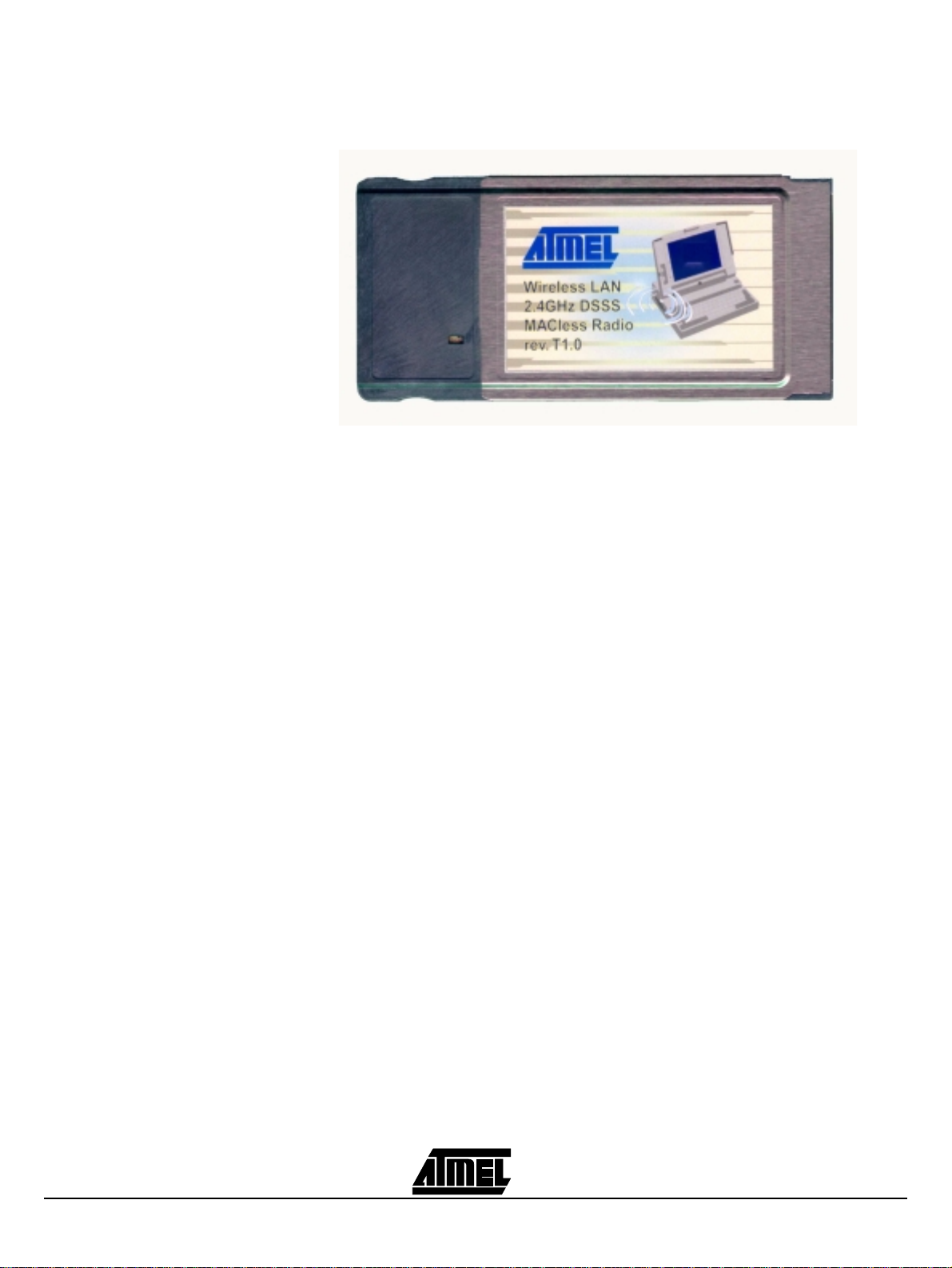
The MACless Radio card required is shown in Figure 2-2.
Figure 2-1.
AP development board
2-1
Page 8
The AP Development Board
Figure 2-2.
MACless Radio
2-2
Page 9

Section 3
Setting the IP Address of the Access
Point
The first step in using the AP is to set its IP Address. This procedure can be
done either through the Ethernet port by using a combination of Arp/Ping commands
and the SNMP Manager, or the USB port by using the DFU utility.
3.1 Using the Ethernet Port
In order to set the Access Point IP address you need to know the Access Point MAC
address. Follow the steps below giving the Access Point a temporary address at the
beginning (Step A) and saving the IP address through the SNMP Manager application
(Step B).
Step A:
1.Connect an Ethernet station and the Access Point on the same subnet
plest way to accomplish that is to connect the Access Point and the Ethernet
station to the same hub. You need to check if the station IP address and the Subnet mask are configured properly. Also the new IP address for the Access Point
must correspond to the Subnet mask.
2.Open a MS-DOS Prompt window and enter a static route in the arp table for the
new IP address you want to assign. Use the arp -s command to do that:
arp -s "new-IP-address" "AP-MAC-address "
For example: arp -s 10.170.254.27 00-00-22-22-22-25
3.Ping the Access Point, using its new IP address.
For example: ping 10.170.254.27
4.If you get a ping reply, then the IP address has been temporarily s et. In order to
set it permantly you need to proceed to Step B without powering off
Point.
Step B:
1.Execute the SNMP Manager application using the IP address as set above (Step A).
2.Save the current configuration through the SNMP Manager application.
3.Open the SNMP Manager application, select “Connect AP-Bridge” option under
the “File” menu. Try to connect to the Access Point, by typing its IP address in
the panel which appears and at the Community field, type "public" and then
. The sim-
the Access
3-1
Page 10
Setting the IP Address of the Access Point
press OK. Type the IP address in the “IP Configuration” window under the
“Setup” menu, “Bridge” submenu. In order to save the configuration select
“Download Changes” under the “File” menu. See also the paragraph “Using the
SNMP Manager” in the section “Access Point Configuration”.
3.2 Using the USB Port
Note:
In order to configure the AP IP address through the USB port, you must use the
DFU Configuration Utility.
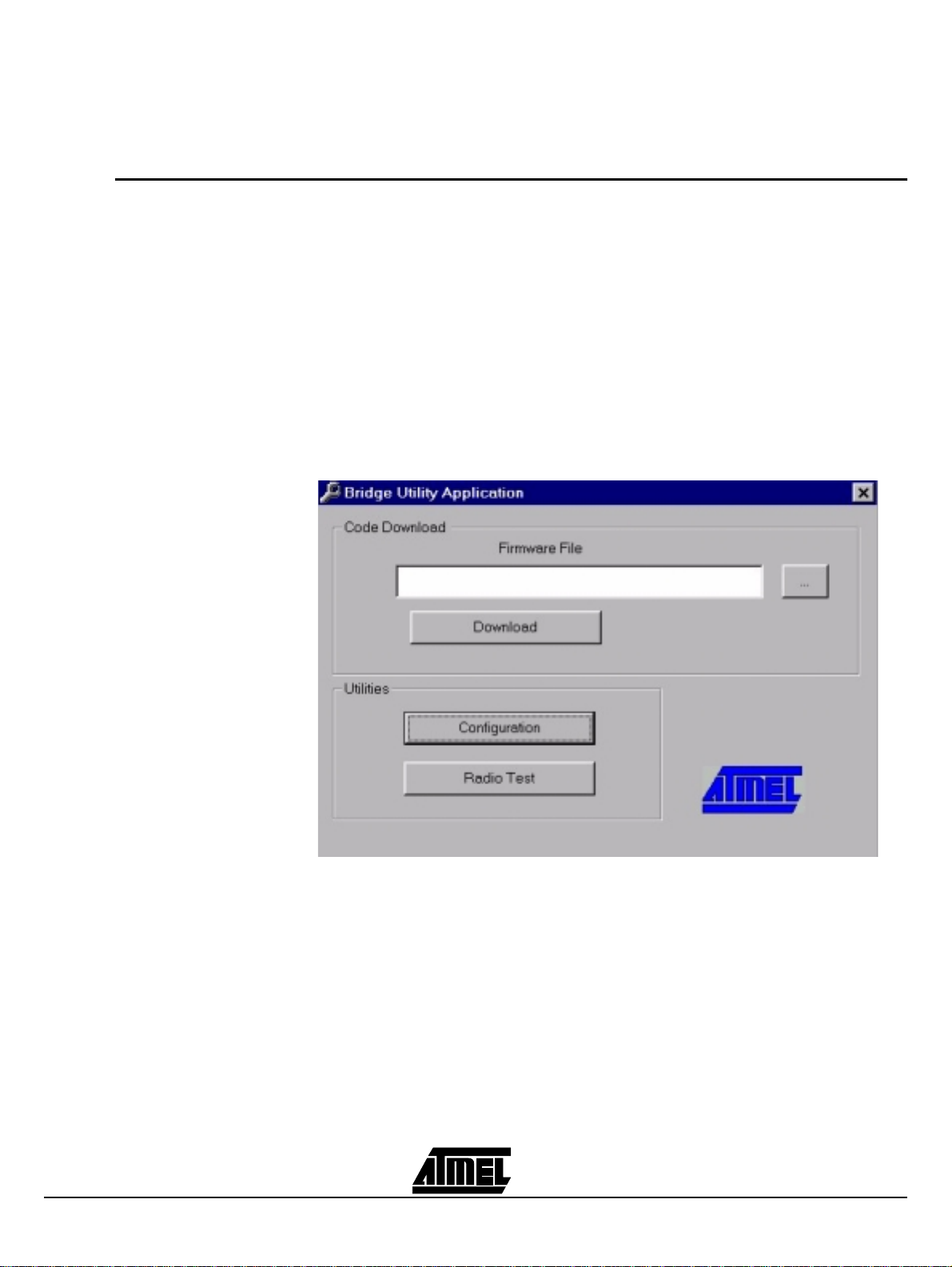
Plug the USB cable to the Access Point USB por t. Open the application DFU.exe which
you will find in the “Utilities” folder of your CD and select the “Configuration” button (Figure 3-1).
Figure 3-1.
This procedure requires the use of the DFU Configuration Utility which can be
used only through the USB port. When you connect the card to the USB port for
the very first time, the operating system will ask for the driver of the card. Please
locate the driver into your CD. At this time, only a driver for MS Windows 98 is
available. After you have completed the installation of the driver, you can use
the DFU Configuration Utility.
DFU Configuration Utility
3-2
Press the “Get” button (Figure 3-2) if you want to view the current IP address. If you
want to set a new IP address, first type the new IP address in the “Ethernet IP Address”
field in the configuration window that is already opened, and then selec t the “Set” command. In order to set the new parameters you need to wait for a few seconds for the
completion of this process.
Page 11

Setting the IP Address of the Access Point
Figure 3-2.
DFU Utility Bridge Configuration window
3-3
Page 12

Setting the IP Address of the Access Point
3-4
Page 13

Section 4
Access Point Configuration
The AP configuration can be done either through the Ethernet port by usi ng the
SNMP Manager application, or the USB port by using the DFU Utility.
4.1 Using the Ethernet Port
4.1.1 How to Install the SNMP Manager
4.1.2 Using the SNMP Manager
In order to configure the AP through the Ethernet port, you must first i nstall the
SNMP Manager application, which is a powerful and reli able tool used for the r emote
configuration of the Access Point through the Ethernet port
In order to install the SNMP Manager you need to extract the “SNMPManager.zip” file,
which you will find into the “Utilities” folder of your CD, in a temporary file and then run
the program “setup.exe”. Follow the instructions of the set-up program and select the
directory where the application wil l be install ed. Finally, a window wil l appear indicating
the completion of the installation.
Note:
On the Start Menu, select SN MP Manager. When the application opens, sel ect
“Connect AP-Bridge” option which is under the “File” menu. Try to connect to the Access
Point, by typing its IP address in the panel which appears and at the Community field,
type "public" and then press OK (Figure 4-1).
Before using the SNMP Manager for configuring the AP, verify that the
Access Point IP address has been set-up following the procedure described in
the section “Setting the IP Address of the Access Point”.
.
4-1
Page 14

Access Point Configuration
Figure 4-1.
Connecting to the AP using the SNMP Manager
In case of a successful connection to the Access Point, the following window appears
(Figure 4-2). Press “OK”.
Figure 4-2.
In case of an unsuccessful connection you receive the following message (Figure 4-3):
Figure 4-3.
If the above error message appears, you need to check if the AP has the desired IP
Address and is connected to the network. In order to check the validity of the IP Address
you need to ping the AP.
Agent found
Agent not found
4-2
Page 15

Access Point Configuration
When the connection has successfully been established, you get a message in the right
bottom corner indicating “All values retrieved”. If the message “Not all values retrieved”
appears, you need to repeat the above procedure (Figure 4-1).
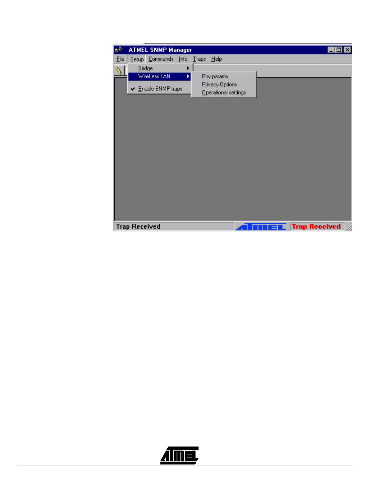
As soon as the connection has been established, you are now able to start viewing or
setting the Access Point parameters. Under the “Setup” menu, there are three options
available (Figure 4-4):
•Bridge
•Wireless LAN
•Enable SNMP Traps
Figure 4-4.
SNMP Bridge menu and submenus
4-3
Under the “Bridge” option, there are two submenus: “IP Configuration” and “Oper ational
Mode”. The “Ethernet Address”, “IP Configuration” and “IP Mask” can either be viewed
or changed through the “IP Configuration” (Figure 4-5). If changes are made, you need
to “Download Changes” under the “File” menu in order to save them.
Page 16

Access Point Configuration
Figure 4-5.
Bridge IP Configuration window
You also need to check that the “Access Point” option is enabled under the “Operational
Mode” submenu (Figure 4-6).
4-4
Page 17

Access Point Configuration
Figure 4-6.
Bridge Operational Mode window
Under the “Wireless LAN” option, the following submenus are available (Figure 4-7):
•Phy params
•Privacy Options
•Operational settings
4-5
Page 18
Access Point Configuration
Figure 4-7.
SNMP Wireless LAN menu and submenus
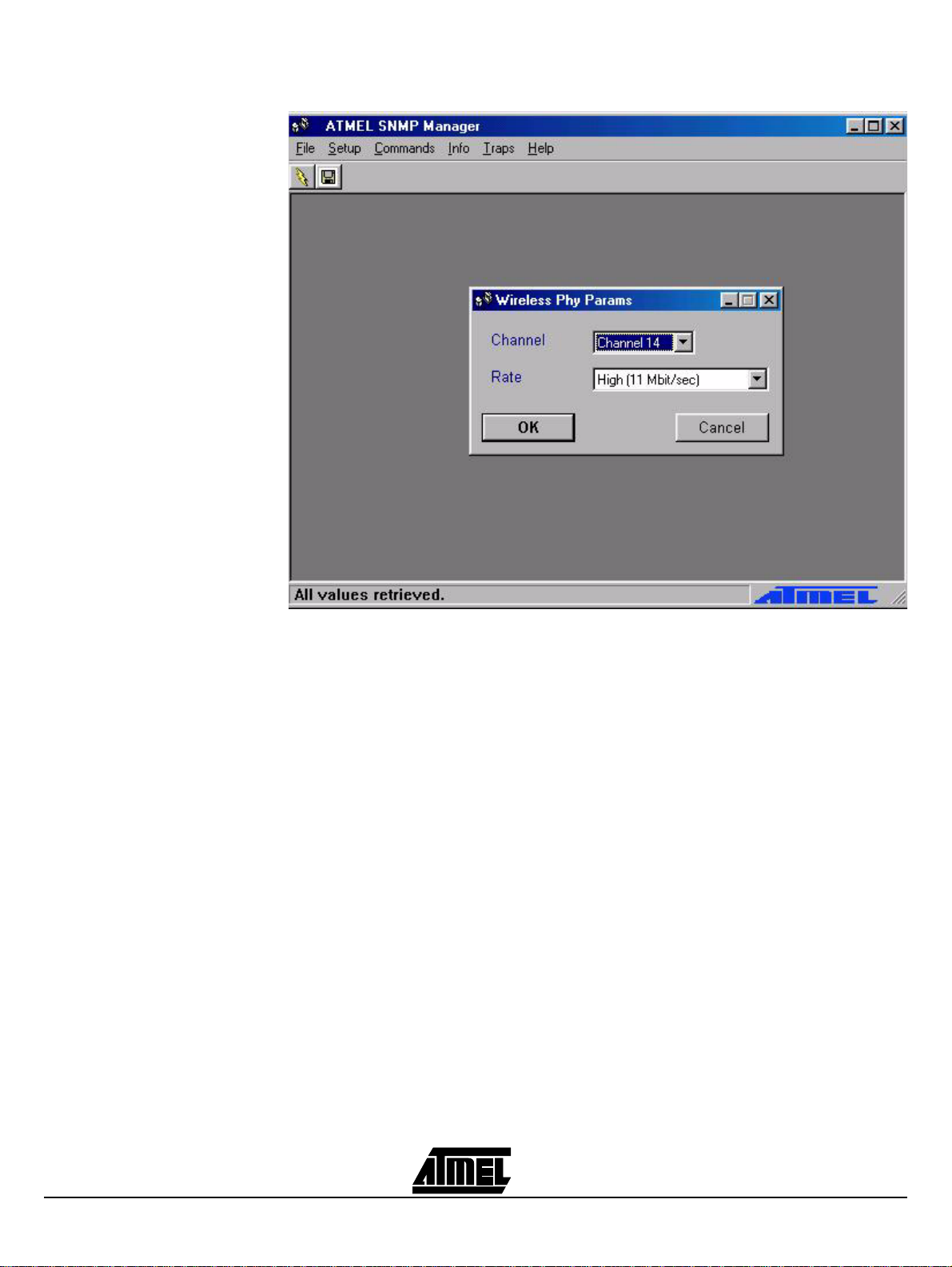
Phy Params (Figure 4-8):
•Channel: Select the channel to be used. There are 14 channels available.
•Rate: Select the rate to be used among the following options 1 Mbps, 2 Mbps, 5.5
Mbps and 11 Mbps.
4-6
Page 19
Access Point Configuration
Figure 4-8.
Wireless Physical Parameters window
Privacy Options (Figure 4-9):
There are four 5 Hex digit encryption keys available, and you must define the value of
the key of your choice. This key is enabled only if the you select it in the “Default key”
option. Enable the WEP (ON/OFF) option in order to activate WEP encryption.
4-7
Page 20

Access Point Configuration
Figure 4-9.
Wireless Privacy Options window
Operational Settings (Figure 4-10):
•ESSID: Select the ESSID to be used.
•Fragmentation: This is the option for the Fragmentation Threshold activation.
•RTS Threshold: This is the option for the RTS Threshold activation.
•Authentication Type (Open System, Shared Key, Both).
•Preamble Type (Short, Long).
4-8
Page 21

Access Point Configuration
Figure 4-10.
Wireless Operational Settings window
Under the “Setup” menu you can either enable or di sable SNMP traps , which are messages displayed in the right bottom corner indicating that an action related to the AP Bridge took place, such as:
•Trap Reassociation:
is received from the AP - Bridge.
•Trap Association:
sender Station's successful association with the Wireles s Bridge.
•Trap Disassociation:
packet is received from a Station.
•Trap Reset:
•Trap Setting IP Address with Ping:
address is set with the transmission of a ping message.
•Trap Start Up:
•Trap Failed To Erase Flash:
flash.
You can see additional information for every Trap Message by selecting the “View
Record” option under the “Traps” menu.
In order to “Reset Device” or “Res tor e Defaults ” you need to s el ect the appr opr iate submenu under the “Commands” menu.
This trap message is sent when the AP-Bridge resets.
This trap message is sent when a Station’s reassociation request
Indicates the reception of an association request packet and the
This trap message is sent when a disassociation notification
This trap message is sent when the AP-Bridge IP
This trap message is sent when Bridge starts up.
This trap message is sent when Bridge fails to erase
4-9
Page 22

Access Point Configuration
Finally, the “Info” menu contains “Wireless and Ethernet Statistics”.
4.1.3 How to Uninstall the SNMP Manager
4.2 Using the USB Port
In order to uninstall SNMP Manager you must go to the ‘Control Panel” (“Star t>Settings->Control Panel”) and press the “Add/Remov e Programs” button. Select the
application from the list and pr ess the “ Add/Remove...” button. P ress “Y es ” when as ked
whether you want to remove this program and its components. A window indicating the
uninstallation progress appears.
Note:
In order to configure the A P through the USB port, you must use the DFU Configuration Utility.
In order to change or view the Bridge parameters you have to plug the USB cable and
then open the DFU.exe application which you will find into the “Utilities” folder of your
CD.
By pressing the “Configuration” button in the main dialog box (Figure 4-11) the Bridge
Configuration dialog appears (Figure 4-12).
Figure 4-11.
This procedure requires the use of the DFU Configuration Utility which can be
used only through the USB port. When you connect the card to the USB port for
the very first time, the operating system will ask for the driver for the card.
Please locate the driver into your CD. At this time, only a driver for MS Windows
98 is available. After you have completed the installation of the driver, you can
use the DFU Configuration Utility.
DFU Configuration Utility
4-10
Page 23

Access Point Configuration
Figure 4-12.
DFU Utility Bridge Configuration window
4-11
The current parameters of the Bridge can be retrieved by pressing the “Get” button in
the Bridge Configuration dialog. You can update the bridge configuration parameters by
setting them first and then selecting the “Set” button.
Network Parameters:
•Ethernet IP Address: The IP Address of the AP
•Ethernet Subnet Mask: The Ethernet station and the Access Point must be on the
same subnet.
Mask.
•Ethernet MAC Address: The MAC address of the AP.
802.11 Parameters:
•Channel: Select the channel to be used. There are 14 channels available.
•Rate: Select the rate to be used among the following options: 1 Mbps, 2 Mbps, 5.5
Mbps, and 11 Mbps.
•ESSID: Select the ESSID to be used.
•Fragmentation Threshold: This is the option for the Fragmentation Threshold
activation.
•RTS Threshold: This is the option for the RTS Threshold activation.
The IP address for the Access Point must correspond to the Subnet
Page 24

Access Point Configuration
•Preamble Type: Select Short or Long Preamble Type.
•Authentication Type: Select Open System or Shared Key Authentication Type.
WEP Keys:
•WEP Key #1-#4: Set the value of the WEP key. WEP keys must be in HEX and in two
bytes per character format e.g. if you want the WEP Key #1 to be 12345, then you
must set it as 0102030405.
•Default Key: Select which of the four WEP Keys is going to be used. By selecting 0,
no WEP encryption will be used.
4-12
Page 25

Section 5
Access Point Firmware Upgrade
The AP firmware upgrade can be done either through the Ethernet port by using
the TFTP Client Utility, or the USB port by using the DFU Utility.
5.1 Using the Ethernet Port
5.1.1 How to Install the TFTP Client
5.1.2 Using the TFTP Client
In order to upgrade the firmware of the AP thr ough the Ethernet port, you must
first install the TFTP Client Utility, which is a powerful and reliable tool used for the
remote firmware upgrade of the Access Point through the Ethernet port
In order to install the Tftp Client Utility you need to extract the given “TFTP.zip” file
which you will find into the “Utilities” folder of your CD, in a temporary folder and then run
the program “setup.exe”. Follow the instructions of the set-up program and select the
directory where the application wil l be install ed. Finally, a window wil l appear indicating
the completion of the installation.
Note:
On the Start Menu, select TFTP. The window of Figure 5-1 appears.
Figure 5-1.
Before using the TFTP Client for upgrading the firmware of the AP, verify
that the Access Point IP address has been set-up following the procedure
described in the section “Setting the IP Address of the Access Point”.
Tftp Client Utility
.
5-1
Type the IP address of the Access P oint in the fi rst edit box of the panel. T hen, browse
for the file xxxx.rom by pressing the “three dots” button. Finally press the "Download"
button (Figure 5-2).
Page 26

Access Point Firmware Upgrade
Figure 5-2.
The Firmware Download procedure will be completed successfully if a message in the
right bottom corner appears indicating “Firmware download has been completed”. If you
receive the message “TimedOut”, i n the r ight bottom corner , during the firmware download procedure, you need to check if the Access Point is powered on and if it has a valid
IP address. In order to check the validi ty of the IP address you must ping the Access
Point.
If you receive the message “Flash Programming in progress” during the firmware download procedure you shouldn’t power off
application press the "Exit" button.
Type the IP address, browse for the file bridge.rom and download
the Access Point. In order to close the
5.1.3 How to Uninstall the TFTP Client
5.2 Using the USB Port
Note:
In order to uninstall SNMP Manager you must go to the ‘Control Panel” (“Star t>Settings->Control Panel”) and press the “Add/Remov e Programs” button. Select the
application from the list and pr ess the “ Add/Remove...” button. P ress “Y es ” when as ked
whether you want to remove this program and its components. A window indicating the
uninstallation progress appears.
Note:
In order to upgrade the fi rmware of the AP through the USB port, y ou must us e
the DFU Configuration Utility.
First of all you have to plug the USB cable and then open the DFU.exe application which
you will find into the “Utilities” folder of your CD.
In the main window of the DFU Configuration Utility (Figure 5-5), select the file xxxx.rom,
by pressing the “three dots” button. Finally press the “Download” button.
If the download procedure has not been completed successfully you must try
again but before starting the download you need to confirm that you are using
the correct firmware file .
This procedure requires the use of the DFU Configuration Utility which can be
used only through the USB port. When you connect the card to the USB port for
the very first time, the operating system will ask for the driver for the card.
Please locate the driver into your CD. At this time, only a driver for MS Windows
98 is available. After you have completed the installation of the driver, you can
use the DFU Configuration Utility.
5-2
Page 27

Access Point Firmware Upgrade
Figure 5-3.
Please keep in mind that this process needs some time to complete. When the DFU
completes successfully a window appears indicating the status of the download (DFU
succeeded, DFU failed). Finally, close the application and unplug the cable.
DFU Configuration Utility
5-3
Page 28

Access Point Firmware Upgrade
5-4
Page 29

Corporate Headquarters
2325 Orchard Parkway
San Jose, CA 95131
TEL (408) 441-0311
FAX (408) 487-2600
Europe
Atmel U.K., Ltd.
Coliseum Business Centre
Riverside Way
Camberley, Surrey GU15 3YL
England
TEL (44) 1276-686-677
FAX (44) 1276-686-697
Asia
Atmel Asia, Ltd.
Room 1219
Chinachem Golden Plaza
77 Mody Road Tsimhatsui
East Kowloon
Hong Kong
TEL (852) 2721-9778
FAX (852) 2722-1369
Japan
Atmel Japan K.K.
9F, Tonetsu Shinkawa Bldg.
1-24-8 Shinkawa
Chuo-ku, Tokyo 104-0033
Japan
TEL (81) 3-3523-3551
FAX (81) 3-3523-7581
Atmel Colorado Springs
1150 E. Cheyenne Mtn. Blvd.
Colorado Springs, CO 80906
TEL (719) 576-3300
FAX (719) 540-1759
Atmel Rousset
Zone Industrielle
13106 Rousset Cedex
France
TEL (33) 4-4253-6000
FAX (33) 4-4253-6001
Atmel Smart Card ICs
Scottish Enterpri se Technology
Park
East Kilbride, Scotland G75 0QR
TEL (44) 1355-803-000
FAX (44) 1355-242-743
Atmel Grenoble
Avenue de Rochepleine
BP 123
38521 Saint-Egreve Cedex
France
TEL (33) 4-7658-3000
FAX (33) 4-7658-3480
Fax-on-Demand
North America:
1-(800) 292-8635
International:
1-(408) 441-0732
e-mail
literature@atmel.com
Web Site
http://www.atmel.com
BBS
1-(408) 436-4309
Atmel Corporation makes no warranty for the use of its products, other than those expressly contained in the Company’s standard warranty which is detailed in Atmel’s Terms and Conditions located on the Company’s web site. The Company assumes no responsibility for
any errors which may appear in this document, reserves the right to change devices or specifications detailed herein at any time without
notice, and does not make any commitment to update the information contained herein. No licenses to patents or other intellectual property of Atmel are granted by the Company in connection with the sale of Atmel products, expressly or by implication. Atmel’s products are
not authorized for use as critical components in life support devices or systems.
Marks bearing “ and/or TM are registered trademarks and trademarks of Atmel Corporation
®
Microsoft
Windows® is a registered trademark of Microsoft.
Printed on recycled paper.
1932A–9/28/00
Page 30

INSTRUCTIONS MANUAL
FEDERAL COMMUNICATIONS COMMISSION
INTERFERENCE STATEMENT
This equipment has been tested and found to comply with the limits for a Class B digital device,
pursuant to Part 15 of the FCC Rules. These limits are designed to provide reasonable
protection against harmful interference in a residential installation. This equipment generates,
uses and can radiate radio frequency energy and, if not installed and used in accordance with
the instructions, may cause harmful interference to radio communications. However, there is
no guarantee that interference will not occur in a particular installation. If this equipment does
cause harmful interference to radio or television reception, which can be determined by turning
the equipment off and on, the user is encouraged to try to correct the interference by one or
more of the following measures:
-- Reorient or relocate the receiving antenna.
-- Increase the separation between the equipment and receiver.
-- Connect the euipment into an outlet on a circuir different from that to
which the receiver is connected.
-- Consult the dealer or an experienced radio/TV technician for help.
CAUTION:
Any changes or modifications not expressly approved by th e grantee of
his device could void the user's authority to operate the equipment.
The antenna(s) used for this transmitter must be installed to provide a separation distance of
at least 20 cm from all persons and must not be co-located or operating in conjunction with any
other antenna or transmitter. End-users and installers must be provided with antenna installation
instructions and transmitter operating conditions for satisfying RF exposure compliance
Page 31

RTW020 AP H/W Specifications
Hardware
Model Type
Frequency Band 2400 – 2483.5 MHz
Number of Allowed
Channels
Ethernet interface
Serial interface
DC Power Adapter DC Power Adapter
Modulation Technique
LED Indicator
Operational Conditions
PCB Dimensions
Support Both Ethernet and 802.3(Max. Bit rate 10Mbps)with
Direct Sequence Spread Spectrum (CCK, DQPSK, DBPSK)
11Mbps Wireless LAN Access Point
11Ch ( for FCC)
13Ch (for ETSI)
14Ch ( for TELEC)
RJ-45 10BaseT connector
USB (console port for configuration)
AC Input:100V~240V (50~60HZ)
DC Output:5V / 2.0A
Active(Green), Line Link(Green)
Power(Red)
Temperature 0-55oC
95%max. Humidity (no condensation allowed)
116.77mm(L)*75.47mm(w)
Antenna type
Average Output Power 20 dBm
Power Consumption Rx :780mA Tx:1.2A
Standards IEEE 802.11b, Wi-Fi –Certified
2 External Antenna
 Loading...