

Page 1

EchoLife HG520s Home Gateway User Manual
Issue 01
Date 2006-08-26
No. 202013
Huawei Technologies Co., Ltd.
Address: Administration Building, Huawei Technologies Co., Ltd.,
Bantian, Longgang District, Shenzhen, 518129, People’s
Republic of China
Website: http://www.huawei.com
Email: terminal@huawei.com
Copyright © Huawei Technologies Co., Ltd. 2006. All rights reserved.
No part of this document may be reproduced or transmitted in any form or by
any means without prior written consent of Huawei Technologies Co., Ltd.
Trademarks and Permissions
and other Huawei trademarks are trademarks of Huawei Technologies
Co., Ltd.
All other trademarks and trade names mentioned in this document are the
property of their respective holders.
Notice
The information in this document is subject to change without notice. Every
effort has been made in the preparation of this document to ensure accuracy
of the contents, but all statements, information, and recommendations in this
document do not constitute the warranty of any kind, express or implied.
This product has been designed to comply with the requirements on
environmental protection. For the proper storage, use and disposal of this
product, national laws and regulations must be observed.
Page 2

This device complies with part 15 of the FCC Rules. Operation is subject to the
following two conditions: (1) This device may not cause harmful interference,
and (2) this device must accept any interference received, including
interference that may cause undesired operation
Class B:
FEDERAL COMMUNICATIONS COMMISSION INTERFERENCE
STATEMENT
This equipment has been tested and found to comply with the limits for a Class
B digital device, pursuant to part 15 of the FCC Rules. These limits are
designed to provide reasonable protection against harmful interference in a
residential installation. This equipment generates, uses and can radiate radio
frequency energy and, if not installed and used in accordance with the
instructions, may cause harmful interference to radio communications.
However, there is no guarantee that interference will not occur in a particular
installation. If this equipment does cause harmful interference to radio or
television reception, which can be determined by turning the equipment off and
on, the user is encouraged to try to correct the interference by one or more of
the following measures:
-Reorient or relocate the receiving antenna.
-Increase the separation between the equipment and receiver.
-Connect the equipment into an outlet on a circuit different from that to which
the receiver is connected.
-Consult the dealer or an experienced radio/ TV technician for help.
CAUTION:
Any changes or modifications not expressly approved by the grantee of this
device could void the user's authority to operate the equipment.
RF exposure warning ·
This equipment must be installed and operated in accordance with provided
instructions and the antenna(s) used for this transmitter must be installed to
provide a separation distance of at least 20 cm from all persons and must not
be co-located or operating in conjunction with any other antenna or transmitter.
End-users and installers must be provide with antenna installation instructions
and transmitter operating conditions for satisfying RF exposure compliance.
Page 3

Safety Precautions
Basic Requirements:
Read this manual carefully before installing and using the
equipment.
Take waterproof measures during storage, transportation and
operation of the equipment.
Avoid collision during storage, transportation and operation of the
equipment.
Without prior written consent from Huawei, no company or individual
is allowed to decompile, disassemble, modify or reverse engineer
the equipment and shall be solely responsible for any effect resulted
from such action.
Environmental Requirements:
Place the equipment in a well-ventilated place. Avoid direct
irradiation of any strong light (such as sunlight).
Keep the equipment clean.
Place the equipment on a flat and stable platform which is beyond
the reach of children.
Do not place heavy objects on the equipment.
Maintain at least 10 cm space around the equipment for heat
dissipation. Do not cover the equipment with any object or block the
ventilation holes of the equipment.
Keep the equipment away from appliances with a strong electric
field or magnetic field, such as a microwave oven and a refrigerator.
Usage:
Use only the power adapter provided with the equipment.
The power supply must meet the equipment specifications.
Before plugging or unplugging the cables, turn off the equipment
and unplug the power supply.
In a lightning storm, turn off the equipment and unplug the power
supply, to avoid lightning strike.
Unplug the power supply if the equipment is not used for a long
time.
Page 4

The temperature of the equipment shell goes up when used for long
hours. This is a normal phenomenon.
Cleaning:
Before cleaning the equipment, turn off the equipment and unplug
the power supply.
Clean the equipment shell with a piece of soft cloth.
Do not spray liquid onto the equipment, to avoid damage to the
internal circuit.
Keep the power socket clean and dry, to avoid electric shock or
other dangers.
Page 5

Table of Contents
Chapter 1 Introduction ........................................................................1
1.1 Functions and Features.........................................................1
1.2 Hardware Configuration ........................................................1
1.2.1 Front Panel .................................................................2
1.2.2 Rear Panel..................................................................3
1.2.3 Splitter.........................................................................4
Chapter 2 Installation of the HG520s..................................................5
2.1 Preparation............................................................................5
2.2 Connecting the HG520s........................................................5
2.3 Establishing Configuration Environment ...............................7
2.3.1 Parameter Configuration.............................................7
2.3.2 Steps...........................................................................7
2.4 Introduction to the Configuration Management Interface......8
Chapter 3 Service Configuration.......................................................10
3.1 Method ................................................................................10
3.1.1 Protocol Model..........................................................10
3.1.2 Steps.........................................................................11
3.2 Service Modes of the HG520s ............................................12
3.3 Configuring the Pure Bridge Mode......................................13
3.3.1 Preparation ...............................................................13
3.3.2 Steps.........................................................................14
3.4 Configuring the PPPoE Mode .............................................16
3.4.1 Preparation ...............................................................16
i
Page 6

3.4.2 Steps.........................................................................17
3.5 Configuring the PPPoA mode .............................................19
3.6 Configuring the DHCP Mode...............................................19
3.6.1 Preparation ...............................................................19
3.6.2 Steps.........................................................................20
3.7 Configuring the Static IP Mode ...........................................21
3.7.1 Preparation ...............................................................21
3.7.2 Steps.........................................................................22
3.8 Configuring the IPoA Mode .................................................24
Chapter 4 Other Settings ..................................................................25
4.1 Changing the IP Address of the LAN of the HG520s..........25
4.2 Changing the Administrator Password of the HG520s .......26
4.3 Restoring the Default Factory Settings ...............................26
Chapter 5 Troubleshooting ...............................................................28
5.1 Quick Failure Location.........................................................28
5.2 FAQs ...................................................................................29
Chapter 6 Technical Specifications ..................................................31
Chapter 7 Appendix ..........................................................................33
7.1 Default Factory Settings......................................................33
7.1.1 Common Default Parameters ...................................33
7.1.2 Default PVC Parameters ..........................................33
7.2 Abbreviations.......................................................................34
ii
Page 7

Chapter 1 Introduction
This chapter introduces functions and structure of the EchoLife
HG520s Home Gateway (hereinafter referred to as the HG520s).
1.1 Functions and Features
The HG520s is a type of Asymmetric Digital Subscriber Line
(ADSL) terminal. Data, video and audio are transmitted through the
common telephone line at a higher rate by the HG520s.
The features of the HG520s are:
High transmission rate: The maximum downstream transfer
rate is 24 Mbit/s; the maximum upstream transfer rate is
1.2 Mbit/s.
Strong network adaptability: The HG520s can be
interconnected with multiple Digital Subscriber Line Access
Multiplexes (DSLAMs).
Strong maintainability: The HG520s provides multiple
indicator status, which is convenient to locate failures.
Easy operation: The HG520s has a simple operation for the
configuration and management page.
1.2 Hardware Configuration
This section introduces the appearance and structure of the
HG520s.
1
Page 8
Note:
Figures of the front panel and the rear panel are only for your reference.
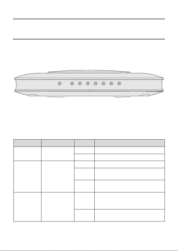
1.2.1 Front Panel
Figure 1-1 shows the front panel of the HG520s.
WLAN
LAN4 LAN3 LAN2 LAN1 INTERNET ADSL POWER
Figure 1-1 Front panel of the HG520s
Table 1-1 shows indicator descriptions of the HG520s in the front
panel.
Table 1-1 Indicator descriptions[a1]
Indicator Color Status Description
Power Green
ADSL Green
INTERNET Green
On Power is on.
Off Power is off.
On DSL connection is established.
Blinking
Off
On
Blinking
The DSL link is in the activation
process.
DSL connection is not
established.
A link is established and activated
in the routing mode, but no data is
being transmitted.
Data is being transmitted in the
routing mode.
2
Page 9
Indicator Color Status Description
Off
The HG520s is in the bridging
mode; or it is in the routing mode
with no link established.
On LAN connection is established.
LAN1~4 Green
Blinking LAN data is being transmitted.
Off
LAN connection is not
established.
On WLAN connection is established.
WLAN Green
Blinking WLAN data is being transmitted.
Off
No WLAN connection is
established.
Note:
PPP = Point-to-Point Protocol
Note:
If the HG520s fails to activate, it tries again after an interval. The ADSL
LINK indicator is off during the interval, lasting for about 1 minute.
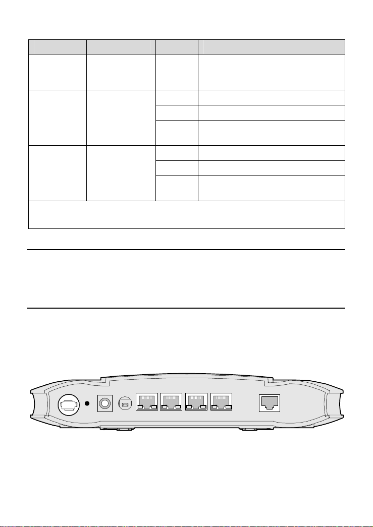
1.2.2 Rear Panel
Figure 1-2 shows the rear panel of the HG520s.
RESET
ON/ OFF
POWER
LAN1 LAN2 LAN3 LAN4
Figure 1-2 Rear panel of the HG520s
3
ADSL
Page 10

Table 1-2 shows descriptions of interfaces and buttons in the rear
panel of the HG520s.
Table 1-2 Descriptions of Interfaces and Buttons[a2]
Interface/Button Description
Antenna Antenna for wireless Internet access.
ADSL
LAN1~4
RESET
POWER Connect to the power adapter.
ON/OFF Switch on/off HG520s.
RJ-11 connector for connection with the telephone jack
or a splitter through a telephone line.
RJ-45 connector for connection with the Ethernet port
of a computer or a LAN hub.
To make the equipment restored and restarted, press
the RESET button and release it within 3 seconds. To
make the equipment restore the default settings of the
HG520s, press the RESET button and release it after 3
seconds. Once you use this function, all your
customized settings will be lost. Therefore, please be
careful with it.
1.2.3 Splitter
The external splitter can efficiently reduce the signal disturbance
on the telephone line. When voice and data are transmitted through the
same telephone line at the same time, you need an external splitter to
separate the voice and data signals:
LINE: Connecting to the phone jack on the wall.
PHONE: Connecting to the telephone.
MODEM: Connecting to the ADSL interface of the HG520s.
4
Page 11
Chapter 2 Installation of the HG520s
This chapter introduces the installation when the HG520s is used
for the first time.
2.1 Preparation
Connect your computer with the HG520s through the Ethernet
interfaces. Before installing the HG520s, make sure that your computer
is equipped with the Ethernet card.
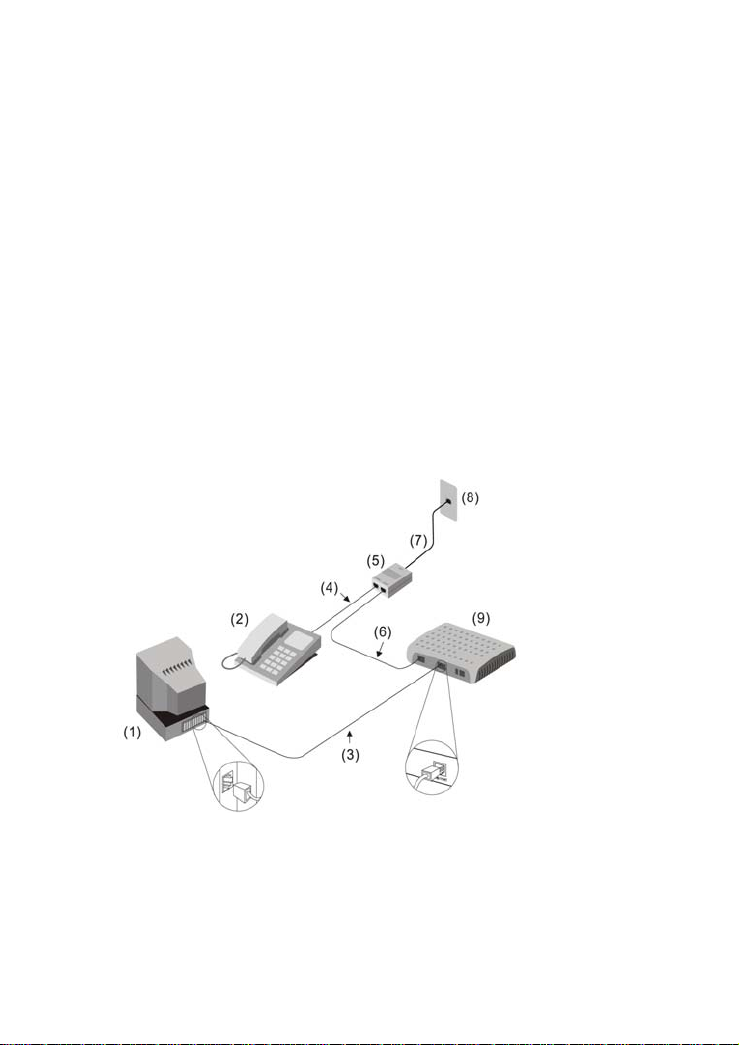
2.2 Connecting the HG520s
Figure 2-1 shows the connection of the HG520s.
[a3][BQF4]
Figure 2-1 Connection of the HG520s
(1) PC (2) Phone (3) RJ-45 Ethernet cable
(4) RJ-11 telephone line (5) Splitter (6) RJ-11 telephone line
(7) RJ-11 telephone line (8) Phone jack (9) HG520s
5
Page 12

Connect the HG520s as follows:
Caution:
Before connecting the HG520s, power off the HG520s and your
computer.
(1) Connect the interfaces of the splitter with the corresponding
equipment by using the telephone line.
Connect the LINE interface of the splitter with the telephone
jack on the wall.
Connect the MODEM interface of the splitter with the ADSL
interface of the HG520s.
Connect the PHONE interface of the splitter with the
interface of the telephone line.
(2) Connect the Ethernet interface of the HG520s with the
Ethernet interface of the computer by using the straight
through network cable.
(3) Plug the output end of the provided power adapter into the
power input interface of the HG520s; plug the other end into
the power socket.
(4) Press the Power button of the HG520s in the rear panel to
power on the HG520s.
Check the Power indicator in the front panel of the HG520s.
If it is on, the HG520s is powered on.
6
Page 13

2.3 Establishing Configuration Environment
You can configure the HG520s on the Web configuration page.
This chapter describes the process to establish the configuration and
management environment of the HG520s.
2.3.1 Parameter Configuration
Before establishing the configuration environment, set the
following parameters.
Table 2-1 Parameters for the configuration environment
Name Description
Administrator username and
password of the HG520s
IP address and subnet mask
of the LAN of the HG520s
IP address and subnet mask
of the computer
Default:
Username: admin
Password: admin
Default:
IP address: 192.168.1.1
Subnet mask: 255.255.255.0
Set them to be in the same network
segment as the IP address of the LAN of the
HG520s
For example:
IP address: 192.168.1.100
Subnet mask: 255.255.255.0
2.3.2 Steps
Follow the steps to establish the configuration environment.
Step To... Do...
1
Connect the
HG520s
For details to connect the HG520s, refer to 2.2
"Connecting the HG520".
7
Page 14

Step To... Do...
The process to unselect this function is described
below taking Internet Explorer 6.0 as an example:
(1) Start the Internet Explorer. Select Tools >
Make sure not
2
to use the proxy
server.
Log in to the
Web
3
configuration
page
Internet Options... to display the Internet
Options dialog box.
(2) Select the Connections tab. Click LAN
Settings....
(3) Deselect Use a proxy server for your LAN
(These settings will not apply to dial-up or
VPN connections).
(1) In the address bar of Internet Explorer, enter
http://192.168.1.1 (the default IP address of
the HG520s). Then press Enter. The login
window is displayed.
(2) Enter the username and the password of the
administrator in the login window.
When the password is authenticated, you can
access the Web configuration page.
Note:
After configuring the working parameters of the HG520s, configure the
computer (such as resetting the IP address of the computer or installing
the dial-up software) according to the configuration status of the
HG520s. Then the computer can access the Internet through the
HG520s. For details, please refer to Chapter 3 "Service Configuration".
2.4 Introduction to the Configuration Management
Interface
The Web configuration page of the HG520s is divided into two
parts:
8
Page 15

The navigation tree: It is on the left side of the page. You can
enter the corresponding configuration and management
interfaces by clicking the related link.
Configuration and management area: It is on the right side of
the page.
9
Page 16

Chapter 3 Service Configuration
This chapter introduces how to use the Web configuration page to
configure the HG520s.
Note:
The figures in the introduction to the configuration operation are only for
your reference.
3.1 Method
3.1.1 Protocol Model
Figure 3-1 shows the protocol model of HG520s connection and
the access equipment DSLAM at the office end.
PVC
ATM
MAC
PHY
(1)
(1) PC (2) HG520s (3) DSLAM
PHY ADSL
(2)
Figure 3-1 Protocol model
10
MACATM
PHYADSL
(3)
Page 17

From the previous figure, you can know that the transmission of
the HG520s and the DSLAM is based on the Asynchronous Transfer
Mode (ATM). To realize all the service modes of the HG520s, configure
the relevant parameters of the HG520s. For example, configure the
Permanent Virtual Channel (PVC) parameter and others.
3.1.2 Steps
The service modes of HG520s can be realized by configuring the
corresponding working parameters.
The steps to realize a service mode are described below.
Step To... Do...
Establish the
configuration
1
environment
Configure the
2
HG520s
Configure your
3
computer
Note:
NIC = Network Interface Card
DHCP = Dynamic Host Configuration Protocol
Refer to 2.3 "Establishing Configuration
Environment".
(1) Select the PVC to be configured.
(2) Select the service mode of this PVC and
configure the working parameters of the
PVC.
(3) Configure functions according to the
requirement.
For example, configure the DHCP function.
(4) Save the configuration and reboot the
HG520s.
Configure the working parameters of the
computer NIC or install the dial-up software in the
computer according to the service mode of the
HG520s.
11
Page 18

3.2 Service Modes of the HG520s
The HG520s supports multiple service modes and the
configuration of the DSLAM at the office end should be taken into
consideration when a service mode is being selected. The various
service modes are listed in Table 3-1.
Table 3-1 the HG520s service mode introduction
Service
Mode
Pure
bridge
PPPoE
PPPoA
DHCP
Static IP
Take the HG520s as pure bridge
equipment.
Use the PPPoE dial-up software of the
computer to dial a number.
Take the HG520s as a router.
Use the built-in PPPoE dial-up software
of the HG520s to dial a number.
Use the PPPoE/PPPoA encapsulation
mode to encapsulate the packets.
Take the HG520s as a router.
Use the PPPoE dial-up software of the
HG520s to dial a number.
Use the PPPoA encapsulation mode to
encapsulate the packets.
Take the HG520s as a router.
The ISP dynamically allocates the IP
address for the HG520s to access the
Internet.
Use the IPoE/IPoA encapsulation
mode to encapsulate the packets.
Take the HG520s as a router.
The HG520s uses the static public IP
address to access the Internet.
Use the IPoE/IPoA encapsulation
mode to encapsulate the packets.
Working Method Configuration
Refer to 3.3
"Configuring the
Bridge Mode".
Refer to 3.4
"Configuring the
PPPoE Mode".
Refer to 3.5
"Configuring the
PPPoA mode".
Refer to 3.6
Configuring the
DHCP Mode".
Refer to 3.7
"Configuring the
Static IP Mode".
12
Page 19

Service
Mode
Take the HG520s as a router.
The HG520s uses the static public IP
IPoA
Note:
ISP = Internet Service Provider
PPPoE = PPP over Ethernet
PPPoA = PPP over ATM
IPoA = Internet Protocol over ATM
address to access the Internet.
Use the IPoA encapsulation mode to
encapsulate the packets.
Working Method Configuration
Refer to 3.8
"Configuring the
IPoA Mode".
Caution:
Some configurations are validated only after they are saved and the
HG520s is rebooted. Follow the prompt in the configuration page to
perform this operation.
3.3 Configuring the Bridge Mode
[a5]
In the pure bridge mode, the HG520s serves as a bridge. You
need to install the PPP dial-up software to realize the dial-up access to
the Internet.
This section describes the process to configure the HG520s to
work in the pure bridge mode and the process to configure your
computer to access the network through the HG520s.
3.3.1 Preparation
Table 3-2 shows the configuration preparation.
13
Page 20

Table 3-2 Configuration for the pure bridge mode
Name Configuration
PVC mode Pure Bridge
PVC operation mode Enable
VPI/VCI Provided by the ISP
Encapsulation Provided by the ISP
Install the PPP dial-up software on your
PPP dial-up software
Username and password for
the PPPoE dial-up
computer to access the Internet (The
Windows XP operating system is provided
with the PPP dial-up software)
Provided by the ISP
3.3.2 Steps
Configure the following equipment:
The HG520s
Your computer
1. Configuring the HG520s
Follow the steps described below:
(1) Log in to the Web configuration page of the HG520s. For the
procedure, refer to 2.3 "Establishing Configuration
Environment".
(2) Select Basic > WAN Settings in the navigation tree to
display the WAN configuration page.
(3) In the WAN configuration page, select the PVC that needs to
be configured. Click the editing icon of the PVC to display the
configuration page.
14
Page 21

(4) Select Pure Bridge in the PVC configuration page. Set the
operation mode to Enable. Configure relevant parameters in
Figure 3-2 according to the values in the Table 3-2.
[a6]
Figure 3-2 Configuring the pure bridge mode
(5) Click Submit.
(6) Select Tools > Save & Reboot in the navigation tree.
(7) Select Save in the Save/Reboot page. Click Submit to save
the configuration.
(8) Select Reboot in the Save/Reboot page. Click Submit to
reboot the HG520s.
2. Configuring your computer
After completing the configuration of the HG520s, you need to
install the PPP dial-up software to access the network.
The Windows XP (Professional) operating system has a built-in
PPPoE dial-up software. To set up a dial-up connection in Windows XP
system, do as follows:
(1) Select Start > All Programs > Accessories >
Communications > Network Connections.
(2) Click Create a new connection in the displayed page.
15
Page 22

(3) Click Next in the New Connection Wizard dialog box.
(4) Select Connect to the Internet and click Next.
(5) Select Set up my connection manually and click Next.
(6) Select Connect using a broadband connection that
requires a username and password and click Next.
(7) Enter the name of the connection. You can name it as you
like. Then click Next.
(8) Select an option from Anyone's use or My use only and
click Next.
(9) Enter the username and password. Then click Next.
(10) Click Finish.
3.4 Configuring the PPPoE Mode
In the PPPoE mode, the HG520s uses the built-in PPP dial-up
software to dial a number. The HG520s serves as a router to connect
your computer to the network.
This chapter describes the process to configure the HG520s to
work in the PPPoE mode and the process to configure your computer to
access the network through the HG520s.
3.4.1 Preparation
Table 3-3 shows the configuration preparation.
Table 3-3 Configuration for the PPPoE mode
Name Configuration
PVC mode PPPoE
PVC operation mode Enable
Default route Enable
DNS Enable
VPI/VCI Provided by the ISP
16
Page 23

Name Configuration
Encapsulation Provided by the ISP
Username and password for the
PPPoE dial-up
DHCP mode of the HG520s Enable the DHCP server
Provided by the ISP
Note:
After the DHCP server is enabled, the HG520s allocates the private IP
address for the computer.
3.4.2 Steps
1. Configuring the HG520s
Follow the steps described below:
(1) Log in to the Web configuration page. For the procedure,
refer to 2.3 "Establishing Configuration Environment".
(2) Select Basic > WAN Settings in the navigation tree to
display the WAN configuration page.
(3) In the WAN configuration page, select the PVC that needs to
be configured. Click the editing icon of the PVC to display the
configuration page.
(4) Select PPPoE in the PVC configuration page. Set the
operation mode Enable. Configure the relevant parameters
in Figure 3-3 according to the values in the
Table 3-3.
17
Page 24

[a7]
Figure 3-3 Configuring the PPPoE mode
(5) Click Submit.
(6) Select Basic > DHCP in the navigation tree to display the
DHCP configuration page.
(7) Select DHCP Server in the DHCP configuration page. Click
Submit.
(8) Select Tools > Save & Reboot in the navigation tree.
(9) Select Save in the Save/Reboot page. Click Submit to save
the configuration.
(10) Select Reboot in the Save/Reboot page. Click Submit to
reboot the HG520s.
18
Page 25

2. Configuring Your Computer
Configure your computer NIC, to enable the computer to
automatically obtain information such as the IP address, gateway and
Domain Name Server (DNS).
3.5 Configuring the PPPoA mode
In the PPPoA mode, the HG520s uses the built-in PPP dial-up
software to dial a number.
Configuring PPPoA mode is similar to configuring PPPoE mode.
The only difference is that you have to select PPPoA in the PVC
configuration mode to configure PPPoA and select PPPoE to configure
PPPoE. For details, refer to 3.4 "Configuring the PPPoE Mode".
3.6 Configuring the DHCP Mode
This section mainly describes the process to configure the
HG520s in the DHCP mode and the process to configure your
computer to access the network through the HG520s.
3.6.1 Preparation
Table 3-4 shows the preparation for the configuration.
Table 3-4 Configuration for the DHCP mode
Name Configuration
PVC mode DHCP
PVC operation mode Enable
Default route Enable
VPI/VCI Provided by the ISP
Encapsulation Provided by the ISP
DHCP mode of the HG520s Enable the DHCP server
19
Page 26

3.6.2 Steps
1. Configuring the HG520s
Follow the steps described below:
(1) Log in to the Web configuration page. For the procedure,
refer to 2.3 "Establishing Configuration Environment".
(2) Select Basic > WAN Settings in the navigation tree to
display the WAN configuration page.
(3) In the WAN configuration page, select the PVC that needs to
be configured. Click the editing icon of the PVC to display the
configuration page.
(4) Select Bridged+DHCP in the PVC configuration page. Set
the operation mode to Enable. Configure the relevant
parameters in Figure 3-4 according to the values in the
Table 3-4.
[a8]
Figure 3-4 Configuring the DHCP mode
(5) Click Submit.
(6) Select Basic > DHCP in the navigation tree to display the
DHCP configuration page.
20
Page 27

(7) Select DHCP Server in the DHCP configuration page. Click
Submit.
(8) Select Tools > Save & Reboot in the navigation tree.
(9) Select Save in the Save/Reboot page. Click Submit to save
the configuration.
(10) Select Reboot in the Save/Reboot page. Click Submit to
reboot the HG520s.
2. Configuring Your Computer
Configure your computer NIC, to enable the computer to
automatically obtain information such as the IP address, gateway and
DNS.
3.7 Configuring the Static IP Mode
This section mainly describes the process to configure the
HG520s in the static IP mode and the process to configure your
computer to access the network through the HG520s.
3.7.1 Preparation
Table 3-5 shows the configuration preparation.
Table 3-5 Configuration for the static IP mode
Name Configuration
PVC mode Static IP
PVC operation mode Enable
Default route Enable
VPI/VCI Provided by the ISP
Encapsulation Provided by the ISP
IP address/subnet
mask
IP address and subnet mask for the HG520s to
access the network are provided by the ISP.
21
Page 28

Name Configuration
IP address of the
gateway
DHCP mode of the
HG520s
IP address of the gateway for the HG520s to
access the network is provided by the ISP.
Enable the DHCP server.
3.7.2 Steps
1. Configuring the HG520s
Follow the steps described below:
(1) Log in to the Web configuration page. For the procedure,
refer to 2.3 "Establishing Configuration Environment".
(2) Select Basic > WAN Settings in the navigation tree to
display the WAN configuration page.
(3) In the WAN configuration page, select the PVC that needs to
be configured. Click the editing icon of the PVC to display the
configuration page.
(4) Select Bridged+Static IP in the PVC configuration page.
Set the operation mode to Enable. Configure relevant
parameters in Figure 3-5 according to the values in the
Table 3-5.
22
Page 29

[a9]
Figure 3-5 Configuring the static IP
(5) Click Submit.
(6) Select Basic > DHCP in the navigation tree to display the
DHCP configuration page.
(7) Select DHCP Server in the DHCP configuration page. Click
Submit.
(8) Select Tools > Save & Reboot in the navigation tree.
(9) Select Save in the Save/Reboot page. Click Submit to save
the configuration.
(10) Select Reboot in the Save/Reboot page. Click Submit to
reboot the HG520s.
2. Configuring Your Computer
Configure your computer NIC, to enable the computer to
automatically obtain information such as the IP address, gateway and
DNS.
23
Page 30

3.8 Configuring the IPoA Mode
Configuring the IPoA mode is similar to configuring the static IP
mode. The only difference is that you have to select IPoA in the PVC
configuration mode to configure IPoA and select Static IP to configure
static IP. For details, refer to 3.7 "Configuring the Static IP Mode".
24
Page 31

Chapter 4 Other Settings
4.1 Changing the IP Address of the LAN of the
HG520s
You can access the Web configuration page of the HG520s
through the IP address of the LAN of the HG520s. The IP address of the
LAN of the HG520s is configured by default, you can change it as
follows:
(1) Log in to the Web configuration page of the HG520s. For the
procedure, refer to 2.3 "Establishing Configuration
Environment".
(2) Select Basic > LAN Settings in the navigation tree to
display the WAN configuration page.
(3) Enter the IP address and the subnet mask in the LAN page.
Click Submit.
(4) Confirm the changing operation according to the prompt in
the page.
Note:
You need to log in again to use the Web configuration page after
configuring the IP address of the HG520s.
Ensure that the IP address of the computer and the IP address of
the HG520s are in the same segment to access the Web
configuration page.
25
Page 32

4.2 Changing the Administrator Password of the
HG520s
The Web manager of the HG520s provides the password
protection function to prevent illegal users from changing the
configuration of the HG520s. The username and the password of the
HG520s are configured by default. To change the administrator
password, follow the steps described below:
(1) Log in to the Web configuration page of the HG520s. For the
procedure, refer to 2.3 "Establishing Configuration
Environment".
(2) Select Tools > System Management in the navigation tree
to display the system management configuration page.
(3) Find the username in the configuration page of system
management. Click the corresponding editing icon to display
the password configuration page.
(4) Enter the new password in the password configuration page.
Click Submit.
4.3 Restoring the Default Factory Settings
Caution:
When you restore the default factory settings, the customized data may
be lost.
There are two options to restore default factory settings:
26
Page 33

1. Using the Reset button
Do as follows:
(1) Find the Reset button in the rear panel of the HG520s
(2) Use a pin to press the Reset button and then release it after
3 seconds.
2. Using the Web Manager
Do as follows:
(1) Select Tools > Save & Reboot in the navigation tree to
display the Save/Reboot page.
(2) Select Factory Setting Reboot in the factory setting reboot
page.
(3) Click Submit.
27
Page 34

Chapter 5 Troubleshooting
5.1 Quick Failure Location
Problem Solution
Ensure that the power adapter matches the
The Power
indicator is not on
The ADSL LINK
indicator is not on
The LAN
indicator is not on
HG520s.
Ensure that the HG520s is connected to the power
supply properly.
Ensure that the Power button is pressed.
Ensure that the ADSL line is connected properly.
Ensure that the telephone line works normally. Run
the check by using a telephone.
Ensure that there is no capacitor or diode in the
connection box.
Ensure that only the network cable provided with the
HG520s is used.
Ensure that the cables are connected properly.
Ensure that the network adapter indicator of your
computer is on.
Ensure that the network adapter works normally.
Check by the following procedure:
Right-click
Select
My Computer to select Properties;
Hardware > Device Manager;
Check whether there are devices with the mark of
! under Network Adapters.
or
If such devices are found, delete and then re-install
them, or change a slot for the network adapter. If the
problem persists, change the network adapter.
?
28
Page 35

Problem Solution
Ensure that all the previous problems are
addressed.
Ensure that the PVC parameters provided by the
ISP are not changed. Otherwise, restore the default
settings.
Ensure that the dial-up software is correctly installed
The Internet
cannot be
accessed
and set properly on your computer.
Ensure that you have entered the right username
and password.
If you still cannot access the Internet after the
dial-up operation, check whether the proxy server
on your IE is correctly configured. The proxy server
must be disabled.
Try different Web sites, in case some Web site fails.
Stop the connection dialing process and retry 5
minutes later.
5.2 FAQs
1. Why does the ADSL connection break so often?
Many possible factors may cause this problem, such as faults in
your ISP's access server, line disconnection and line disturbance. You
can check as follows:
(1) Make sure that the ADSL line is connected properly.
(2) Keep the HG520s away from appliances with strong electric
fields or magnetic fields, such as a microwave oven or a
refrigerator.
(3) Make sure that no telephone or fax machine is connected
directly to the ADSL line.
(4) Replace the old ISA network adapter with a new 10/100 M
PCI network adapter and install the latest driver.
(5) Find help on http://www.huawei.com.
29
Page 36

2. What to do if the username and the password of the Web
configuration page are forgotten?
If the username and the password of the Web configuration page
are forgotten, configure the HG520s to the default factory settings. Use
the default username and password to access the Web manager.
For restoring the default factory settings, refer to 4.3 "Restoring
the Default Factory Settings". For the username and the password of
the HG520s, refer to 7.1 "Default Factory Settings".
30
Page 37

Chapter 6 Technical Specifications
Main Technical Specifications
ITU G.992.1 (G.dmt) Annex A
ADSL standard
Standard
ADSL2 standard
ADSL2+ standard ITU G.992.5 Annex A
G.dmt
T1.413
Data transfer
rate
G.lite
G.992.5 (ADSL2+)
Physical Features and Environment Requirements
Power consumption < 4 W
Power adapter
Temperature of the
working environment
Humidity of the working
environment
Dimensions (L % W %
H)
Input: 220 V AC 50 Hz
Output: 12 V AC 0.8 A
℃ – 40℃ (32℉ – 104℉)[a10]
0
5% – 95% (non-condensing)
135 mm
ITU G.992.2 (G.lite) Annex A
ITU G.994.1 (G.hs)
ANSI T1.413 Issue 2
ITU G.992.3 (G.dmt.bis) Annex A
ITU G.992.4 (G.lite.bis) Annex A
The maximum downstream rate
is 8 Mbit/s
The maximum upstream rate is
896 kbit/s
The maximum downstream rate
is 1.5 Mbit/s
The maximum upstream rate is
512 kbit/s
The maximum downstream rate
is 24 Mbit/s
The maximum upstream rate is
1.2 Mbit/s
% 110 mm % 28 mm
31
Page 38

Weight 180 g
32
Page 39

Chapter 7 Appendix
7.1 Default Factory Settings
7.1.1 Common Default Parameters
Item Default Value
Username of administrator Admin
Password of administrator Admin
IP address 192.168.1.1
Subnet mask 255.255.255.0
DHCP mode None
NAT Enable
7.1.2 Default PVC Parameters[a11]
Sequence
No.
0 Bridge 0 35
1 Bridge 0 34
2 Bridge 0 35
3 Bridge 0 36
4 Bridge 0 37
5 Bridge 0 38
6 Bridge 0 39
7 Bridge 0 40
Mode VPI VCI
33
Page 40

7.2 Abbreviations
ADSL Asymmetric Digital Subscriber Line
ATM Asynchronous Transfer Mode
DHCP Dynamic Host Configuration Protocol
DNS Domain Name Server
DSLAM Digital Subscriber Line Access Multiplex
IP Internet Protocol
IPoA Internet Protocol over ATM
ISP Internet Service Provider
LAN Local Area Network
PC Personal Computer
NIC Network Interface Card
PPP Point-to-Point Protocol
PPPoA PPP over ATM
PPPoE PPP over Ethernet
PVC Permanent Virtual Channel
VCI Virtual Channel Identifier
VPI Virtual Path Identifier
WAN Wide Area Network
34
 Loading...