

Page 1

ADSL Router (MODEL RTA1435VW)
27
USER GUIDE
Copyright ©2008.
January 2008
Page 2

User Guide
ADSL Router (RTA1435VW)
TABLE OF CONTENTS
2
28
1.
PRODUCT DESCRIPTION..................................................................................................................................3
2.
SAFETY INSTRUCTIONS ..................................................................................................................................4
3.
HARDWARE FEATURES ...................................................................................................................................5
3.1LED Indicators...........................................................................................................................................5
3.2Connector Descriptions..............................................................................................................................7
INSTALLING THE HARDWARE.......................................................................................................................8
4.
4.1Installation Requirements ..........................................................................................................................8
4.2
4.3
4.4Hardware Installation.................................................................................................................................9
CONFIGURING THE ROUTER FOR INTERNET CONNECTION ................................................................10
5.
5.1Accessing the Router for the First Time ..................................................................................................10
5.2
5.3
5.4
5.5Establishing a WAN Ethernet Session using VersaPort™2.....................................................................18
CONFIGURING WIRELESS OPERATIONS....................................................................................................19
6.
6.1Basic Wireless Configuration ..................................................................................................................19
6.2
6.3
6.4
6.5
6.6Advanced Wireless Settings ....................................................................................................................25
PUBLICATION INFORMATION......................................................................................................................26
7.
Before You Begin ......................................................................................................................................8
Microfilters ................................................................................................................................................8
Confirming a DSL Sync...........................................................................................................................12
Establishing a PPP Session ......................................................................................................................13
Establishing a Routed IP Connection.......................................................................................................16
Simple Config - Wi-Fi Protected Setup (WPS) .......................................................................................20
Wireless Security .....................................................................................................................................21
Connecting PCs via Wireless...................................................................................................................23
Using MAC Filtering ...............................................................................................................................24
530-300547 Rev. 2
January 2008
Page 3
User Guide
ADSL Router (RTA1435VW)
1. PRODUCT DESCRIPTION
3
28
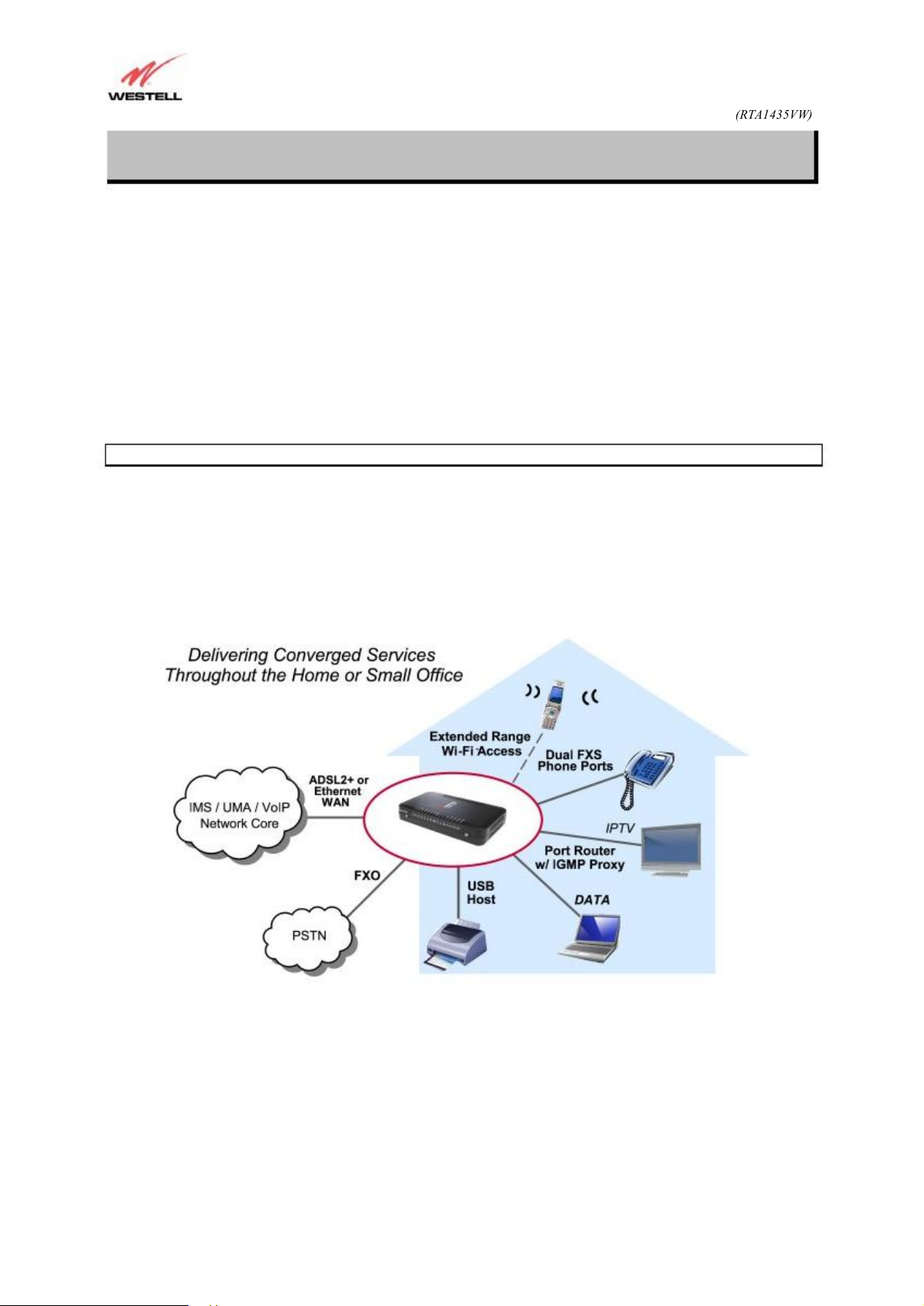
The ADSL Router combines the functionality of a Voice over (VoIP) Analog Terminal Adapter with
that of a Westell ADSL Router. The Router enables you to connect analog phones or dual-mode Wi-Fi/GMS phones
to the Router to make or receive phone calls over the Internet, and supports a variety of networking interfaces such as
wireless 802.11b/g, ADSL 2/2+, and Ethernet. The Router also functions as a 4-port Router and enables you to
connect multiple PCs on your LAN to the Internet. The Router’s VersaPort™2 interface enables you to uplink your
Router to other ADSL network devices, and the 802.11 wireless interface enables you to establish a secure wireless
connection with your ISP’s wireless network equipment.
With the ADSL Router, you can to use the same phone line for simultaneous voice/fax communications and
high-speed Internet access, eliminating the need for dedicated phone lines for voice and data needs. ADSL
connection is “always-on,” ending the hassles of dial-up modems and busy signals, and installation is easy ... no tools
... no headaches. Simply connect the hardware, apply power, and perform the simple software configuration for
Router and you are on the Internet.
Hereafter, the ADSL Router will be referred to as the “Router.”
ADSL Multiple PC Setup
530-300547 Rev. 2
January 2008
Page 4
User Guide
ADSL Router (RTA1435VW)
2. SAFETY INSTRUCTIONS
Never install any telephone wiring during a lightning storm.
Never install telephone jacks in wet locations unless the jack is specifically designed for wet locations.
Never
4
28
The following important safety instructions should be followed when using your telephone equipment.
WARNING: Please save these instructions.
Do not use this product near water, for example, near a bathtub, washbowl, kitchen sink or laundry tub, in a
wet basement or near a swimming pool.
Avoid using a telephone (other than a cordless type) during an electrical storm. There may be a remote risk
of electric shock from lightning.
Do not use the telephone to report a gas leak in the vicinity of the leak.
Do not connect this equipment in an environment that is unsuitable. The voice over IP (VoIP) ports of the
equipment are suitable for connection to intra-building or non-exposed wiring only.
touch non-insulated telephone wires or terminals unless the telephone line has been disconnected at
the network interface.
Use caution when installing or modifying telephone lines.
WARNING
Risk of electric shock. Voltages up to 140 Vdc (with reference to ground) may
be present on telecommunications circuits.
530-300547 Rev. 2
January 2008
Page 5
User Guide
ADSL Router (RTA1435VW)
3. HARDWARE FEATURES
3.1 LED Indicators
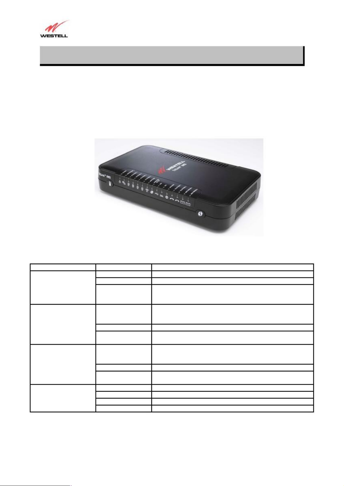
This section explains the LED States and Descriptions of your Router. LED indicators are used to verify the unit ’s
operation and status.
Figure 1. Front View of IMS Router
LED
POWER
VERSAPORT™2
(LAN/WAN)
ETHERNET
(LAN 1-4)
WIRELESS
530-300547 Rev. 2
State
Solid Green
OFF
Solid Red
Solid Green
Flashing Green
Off
Solid Green
Flashing Green
OFF
Solid Green
Flashing Green
Solid Amber
Off
LED States and Descriptions
Description
Router power is ON.
Router power is OFF.
POST (Power On Self Test), Failure (not bootable) or Device
Malfunction. Note: The Power LED should be red no longer than
two seconds after the power on self test passes.
Powered device is connected to the associated port (includes devices
with wake-on LAN capability where slight voltage is supplied to an
Ethernet connection).
10/100 Base-T Ethernet WAN activity is present in either direction.
Router power is OFF, no cable, or no powered device is connected to
the associated port.
Powered device is connected to the associated port (includes devices
with wake-on LAN capability where slight voltage is supplied to an
Ethernet connection).
Ethernet LAN activity is present (LAN traffic in either direction).
Router power is OFF, no cable or no powered device is connected to
the associated port.
Wireless is enabled and functioning.
Wireless LAN activity present (traffic in either direction).
Wi-Fi Protected Setup in progress
Wireless is disabled or not functioning.
5
January 2008
Page 6
User Guide
No DSL signal.
Note: If the IP or PPP session is dropped due to an idle timeout, the
No Message.
No Message.
6
ADSL Router (RTA1435VW-D27)
Wireless Setup (WPS)
USB
DSL
INTERNET
TELEPHONE 1
TELEPHONE 2
Message Waiting 1
(Line 1 message waiting)
Message Waiting 2
(Line 2 message waiting)
Solid Green
Flashing Green
Flashing Green
Flashing Green
OFF
Solid Green
Flashing Green
OFF
Solid Green
Flashing Green
Solid Red
Flashing Red
Solid Amber
Off
Solid Green
Flashing Green
Solid Red
OFF
Solid Green
Flashing Green
Off
Solid Green
Flashing Green
Off
Flashing Green
Off
Flashing Green
Off
ADSL Router (RTA1435VW)
Wi-Fi Protected Setup was successful (on for 300 seconds)
Wi-Fi Protected Setup in progress (on for 0.2 seconds off for 0.1
seconds repeating)
Wi-Fi Protected Setup error (on for 0.1 seconds off for 0.1 seconds
repeating)
Wi-Fi Protected Setup session overlap detected (on for 0.12 seconds
off for 0.1 seconds repeating for 0.1second, Off for 0.5 second
repeating)
Wi-Fi Protected Setup is not activated or modem power off
USB device is recognized and drivers are properly installed.
USB is transferring data.
Modem power is OFF, USB device not present, or USB device not
recognized by modem.
Good DSL sync.
DSL attempting to sync.
Device has unsuccessfully attempted DSL sync for three minutes.
Router is in safeboot mode.
Router power is OFF.
Internet link established.
IP connection established and IP Traffic is passing through device
(in either direction).
light will remain solid green, if an ADSL connection is still present.
If the session is dropped for any other reason, the light is turned
OFF. The light will turn red when it attempts to reconnect and
DHCP or PPP fails).
Device attempted to become IP connected and failed (no DHCP
response, no PPP response, PPP authentication failed, no IP address
from IPCP, etc.).
Modem power is OFF, Modem is in Bridge Mode, or the connection
is not present.
SIP registration succeeded. Attached device is registered with VoIP
server.
Attached device is attempting to establish a VoIP call.
Power off, line not provisioned, line not registered with VoIP server.
SIP registration succeeded. Attached device is registered with VoIP
server.
Attached device is attempting to establish a VoIP call.
Power off, line not provisioned, line not registered with VoIP server.
Message Waiting.
Message Waiting.
530-300547 Rev. 2
January 2008
Page 7
User Guide
Name
Green
Black
Yellow
Yellow
Black
Blue
7
ADSL Router (RTA1435VW-D27)
ADSL Router (RTA1435VW)
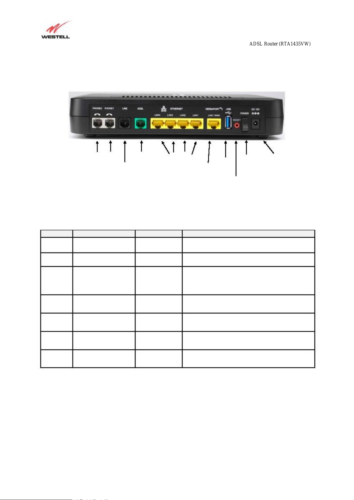
Figure 2. Rear View of the IMS Router
PHONE 2 and 1
LINE
(FXO)
DSL
ETHERNET
(E1, E2, E3, E4)
3.2 Connector Descriptions
The following chart displays the connector types for the IMS Router.
Color
ADSL
LINE
VERSAPORT™2
ETHERNET
POWER
Type
RJ-11
RJ-11
RJ-45
RJ-45
Barrel connector
POWER
USB
VERSAPORT™ 2
Function
Connects to an ADSL-equipped telephone jack or
DSL connection of a POTS splitter.
Connects to a PSTN telephone jack for use when
power is lost.
VERSAPORT™2 can function as a 10/100 Base-T
Ethernet connection to a WAN-side networking
device. (e.g., xDSL, etc.), a DMZ LAN Port, or a fifth
Ethernet LAN Port, depending on the configuration.
10/100 Base-T Ethernet Connection to PC or Hub.
Connection to DC Power Adaptor.
Switch
RESET Button
DC 12V
Connector
Gray
530-300547 Rev. 2
PHONE 1 and 2
USB
RJ-11
Type A
Telephone Port connection to phone cable.
Connects a USB 2.0 Type A Host device to the router.
January 2008
Page 8

User Guide
N
8
ADSL Router (RTA1435VW-D27)
ADSL Router (RTA1435VW)
4. INSTALLING THE HARDWARE
4.1 Installation Requirements
To install your Router, you will need one of the following:
A Network Interface Card (NIC) installed in your PC
An IEEE 802.11b/g adapter
OTE: Internet Service Provider (ISP) connection requirements may vary. Consult your ISP for installation
instructions. Please wait until you have received notification from your ISP that your DSL line has been activated
before installing the Router.
4.2 Before You Begin
Make sure your kit contains the following items:
Westell® IMS Router
Power Supply
RJ-45 Ethernet cable (straight-through) (yellow)
RJ-11 ADSL Cable (green)
RJ-11 Line Cable (black)
4.3 Microfilters
ADSL signals must be blocked from reaching each telephone, answering machine, fax machine, computer modem or
any similar conventional device. Failure to do so may degrade telephone voice quality and ADSL performance.
Install a microfilter if you desire to use the DSL-equipped line jack for telephone, answering machine, fax machine
or other telephone device connections. Microfilter installation requires no tools or telephone rewiring. Just unplug the
telephone device from the baseboard or wall mount and snap in a microfilter. Next, snap in the telephone device.
You can purchase microfilters from your local electronics retailer or contact the original provider of your DSL
equipment. Microfilters are not required on the telephone devices attached to the voice over IP (VoIP) ports.
530-300547 Rev. 2
January 2008
Page 9
User Guide
NOTE: If you are using the Router in conjunction with an Ethernet Hub or Switch, refer to the manufacturer ’s
NOTE: When using the yellow VERSAPORT
4.
6.
3.
9
ADSL Router (RTA1435VW-D27)
ADSL Router (RTA1435VW)
4.4 Hardware Installation
instructions for proper installation and configuration. When using a Microfilter, be certain that the DSL phone cable
is connected to the “ DSL/HPN” non-filtered jack. Please wait until you have received notification from your ISP that
your DSL line has been activated before installing the Router. Askey recommends the use of a surge suppressor
to protect equipment attached to the power supply. An additional Ethernet cable may be required depending on
the installation method you are using. Ethernet cables can be purchased at your local computer hardware retailer.
IMPORTANT: Before you connect via 10/100 Base-T, you must have an available Ethernet card installed in your
computer. If your Ethernet card does not auto-negotiate, you must set it to half duplex. Refer to the Ethernet card
manufacturer’s instructions for installing and configuring your Ethernet card.
1. Connect the green ADSL phone cable from the connector marked ADSL on the rear panel of the Router to the
DSL-equipped telephone line jack on the wall. IMPORTANT: Do not use a Microfilter on this connection. You
must use the phone cord that was provided with the kit.
Connect the black Line cable from the connector marked LINE on the rear panel of the Router to the DSL-
2.
equipped telephone line jack on the wall. IMPORTANT: You MUST use a Microfilter on this connection.
Connect the yellow Ethernet cable (provided with your kit) from any one of the Ethernet jacks marked
ETHERNET on the rear panel of the Router to the Ethernet port on your computer. Repeat this step to connect
up to three additional PCs to your Router.
yellow Ethernet cable (provided with your kit) or any other Ethernet cable to the VERSAPORT™2 jack as the
VERSAPORT™2 jack will function as a fifth Ethernet port. You may also connect to any of the four yellow
Ethernet jacks on the rear panel of the Router as they serve as an Ethernet switch.
Connect the power supply cord to the power connector marked DC 12V on the rear panel of the Router. Plug the
other end of the power supply into a wall socket, and then turn on the power switch (if it is not already turned on).
5.
Check to see if the DSL LED is solid green. If the DSL LED is solid green, the Router is functioning properly.
Check to see if the Ethernet LED is solid green. Solid/Flashing green indicates that the Ethernet connection is
functioning properly.
Congratulations! You have completed the Hardware installation for your Router. You must now proceed to section 5,
“Configuring the Router for Internet Connection.”
™2 jack in Private LAN mode, you may connect either the
530-300547 Rev. 2
January 2008
Page 10

User Guide
10
ADSL Router (RTA1435VW-D27)
ADSL Router (RTA1435VW)
5. CONFIGURING THE ROUTER FOR INTERNET CONNECTION
To browse the Internet using your IMS Router, you must confirm your DSL sync, set up your account profile, and
establish an Internet session with your Internet Service Provider (ISP).
5.1 Accessing the Router for the First Time
5.1.1 Navigating the GUI
After connecting the hardware for your IMS Router, start your Internet browser and type http://192.168.1.1/ in the
browser’s address bar. Next, press ‘Enter’ on your keyboard. The following Password screen will be displayed. The
User Name is “admin” and Password is “password”. The Home screen will then appear.
530-300547 Rev. 2
January 2008
Page 11

User Guide
11
ADSL Router (RTA1435VW-D27)
The Home screen is separated into 4 sections highlighting common applications within the router. Broadband
Connection provides a quick link to the Internet Account Profile. Quick Links provide links to 4 of the most
common applications performed within the router. My Network provides a brief description of the devices
connected via the local network. Services provide an area for the Internet Service Provider to place links to features
or services (i.e. their website).
ADSL Router (RTA1435VW)
5.1.2 My Network
The following screen will appear if you select My Network from the Home screen. This screen displays information
about the devices connected to the local network.
530-300547 Rev. 2
January 2008
Page 12

User Guide
12
ADSL Router (RTA1435VW-D27)
ADSL Router (RTA1435VW)
5.2 Confirming a DSL Sync
You must have active DSL service before the Router can synchronize with your ISP ’s equipment. To determine if
the DSL sync is established, check the Router’s DSL LED. If the DSL LED is not solid green, you do not have a
DSL sync established. Contact your Internet service provider for further instructions. The Router will handle
transmission rates up to 8 Mbps. Your actual DSL rates may vary depending on your Internet service provider.
After connecting the hardware for your IMS Router, start your Internet browser and type http://192.168.1.1/ in the
browser’s address bar. Next, press ‘Enter’ on your keyboard. The following Home screen will be displayed.
View the DSL Speed at the Broadband Connection field. If the status reads Down, check the DSL physical connection.
The following screen shows the DSL connection rate with values that indicate a successful DSL SYNC has been
established. The connection rate values represent the transmission speed of your DSL line. (The Router may take time to
report these values.)
530-300547 Rev. 2
January 2008
Page 13

User Guide
1.
2.
13
ADSL Router (RTA1435VW-D27)
ADSL Router (RTA1435VW)
5.3 Establishing a PPP Session
Important: Before you set up a connection profile, you must obtain your Account ID and Account Password from
your Internet service provider. You will use this information when you set up your account parameters. If you are at
a screen and need help, click the Help link located at the right of the screen.
After you have confirmed your DSL sync, click Edit Connection in the Broadband Connection section of the
Home screen to set up your connection profile. The following Edit screen enables you to add new connection
profiles to or edit existing connection profiles. Connection profiles can be associated with specific service settings,
such as connection settings or NAT services, enabling you to customize your Router for specific users.
Click on the Edit button to the right of the Connection Name.
Type in a Connection Name to identify the account profile.
The Connection Name field allows you to enter the desired name that you wish to use for each
profile that you set up. You may create and store up to eight unique connection profiles in your
Router, which you can use once you establish a PPP session with your Internet Service Provider
(ISP). This field allows a maximum of 64 characters.
530-300547 Rev. 2
January 2008
Page 14

User GuideADSL Router (RTA1435VW)
3. 4.
NOTE: If you click
9.
14
ADSL Router (RTA1435VW-D27)
IMPORTANT: When you first establish a PPP session, you must use the factory default connection name
“MainPPP” to connect to your ISP. Then, if you want set up additional profiles, you may use connection names
of your choice. The Connection Name is the name associated each connection profile. The Account ID and
Account Password are provided by your Internet service provider and must be used for each connection profile
that you set up.
Type in the Account ID as provided by the Internet Service Provider.
The Account ID allows a maximum of 255 characters.
Type in the Account Password as provided by the Internet Service Provider.
The Account Password will be masked with asterisks for extra security. This field allows a
maximum of 255 characters.
At the field labeled Connection, select the connection type (Manual, On Demand, or Always On) that you
5.
want to use with this connection name. The factory default connection type is “Always On.”
Select the MRU Negotiation and LCP Echo settings that you want to use with this connection name. For
6.
details on these settings, click on the Help link on the right side of the screen.
Click Save to save any changes that you have made to this screen.
7.
Click Back to return to the main Connection screen.
8.
changes that you have made to this screen will not take effect. You must click Save to save the settings.
Back before you click Save, the previously saved settings will remain active, and any recent
After you have set up your connection profile and clicked Save, click the Connect button to establish a PPP
session.
530-300547 Rev. 2
January 2008
Page 15

User Guide
NOTE: Whenever the PPP Status displays
NOTE: If you experience problems establishing a PPP session, contact your ISP for further instructions.
15
ADSL Router (RTA1435VW-D27)
ADSL Router (RTA1435VW)
connection setting is set to “Always On” or “On Demand,” after a brief delay, the PPP session will be established
automatically and the PPP Status will display Up. If the connection setting is set to “Manual,” you must click on the
Connect button to establish each PPP session. Once the PPP session has been established (PPP Status displays UP),
you may proceed with your Router’s configuration.
When the Connection screen displays Up in the PPP Status field, this indicates that you have established a PPP
session with your ISP. As shown in the following screen, MainPPP is the factory default connection name used to
establish a PPP session with your ISP. After you have established your PPP session, you may now use other
connection profiles that you have created via the Edit button. The name of the profile will be displayed in the
Connection Name field. If needed, refer to section 5.3 Establishing a PPP session for details on setting up a
connection profile.
Down, you do not have a PPP session established. If your Router ’s
After you have established a PPP session with your ISP, you are ready to browse the Internet.
530-300547 Rev. 2
January 2008
Page 16

User Guide
16
ADSL Router (RTA1435VW-D27)
ADSL Router (RTA1435VW)
5.4 Establishing a Routed IP Connection
After you have confirmed your DSL sync, click on the Advanced tab. Hold the mouse over WAN and select VCs to
set up your connection profile.
1.
Click on the first Edit button to the right of PPPoE.
2.
Click on the down arrow next to Protocol and select Routed IP.
530-300547 Rev. 2
January 2008
Page 17

User GuideADSL Router (RTA1435VW)
17
ADSL Router (RTA1435VW-D27)
3. If an IP Address was not assigned by the ISP, leave the radius button next to “Obtain addresses
automatically”. Otherwise, click the radius button next to “Use the following static addresses ” and enter the
information provided by the ISP as seen below.
4.
Click Save to save the configuration to the router.
5.
Click on the Home screen to verify the Internet connection is Up.
530-300547 Rev. 2
January 2008
Page 18

User Guide
3.
18
ADSL Router (RTA1435VW-D27)
ADSL Router (RTA1435VW)
5.5 Establishing a WAN Ethernet Session using VersaPort™2
Important: Before you set up a connection profile, an Account ID and Account Password may be required from
your Internet service provider. You will use this information when you set up your account parameters. If you are at
a screen and need help, click the Help link located at the right of the screen.
After you have confirmed your DSL sync, click on the Advanced tab. Hold the mouse over WAN and select
VersaPort to set up your connection profile.
1.
Click the radius button next to Ethernet WAN uplink to configure the router for an Ethernet connection.
2.
Select the Protocol as assigned by the Internet Service Provider. This will be either PPPoE or Routed IP.
If PPPoE is selected, you will be required to enter an Account ID and Account Password as
described in section 5.3. This will be provided by the Internet Service Provider (ISP).
If Routed IP is selected you may be required to enter IP Address information.
If IP Address information was provided by the ISP, enter the information as seen below.
530-300547 Rev. 2
January 2008
Page 19

User Guide
NOTE: Upon the Router’s initial configuration, the “Hide SSID” feature cannot be used until the wireless adapter
1. 2. 3. 4. 5. 6.
19
ADSL Router (RTA1435VW-D27)
ADSL Router (RTA1435VW)
6. CONFIGURING WIRELESS OPERATIONS
6.1 Basic Wireless Configuration
The following settings will be displayed if you select Basic from the Wireless tab. The router is pre-configured to
allow wireless operation.
All configuration performed on the Basic Setup screen is optional. Changing these parameters will make your router
unique within your networking environment.
being used in the PC has been configured and associated to the Router.
Wireless Operation enables or disables the wireless operation within the router. If wireless is not desired,
click on the down arrow and select Disable.
The SSID is a unique name that identifies your router in a wireless environment. The default SSID is the
serial number of the router. To change the SSID, type in a unique name of choice. The unique name must
be 32 characters or less in length.
Channel is the channel number used by the router to transmit and receive data. By default, the channel is
set to 6. The router can be set to any channel (1-11). The computer ’s wireless adapter will automatically
detect the operating channel.
Mode tells the router how to communicate to the wireless adapters within the network. Possible mode types
are Mixed, 802.11b, 802.11b+, and 802.11g.
Frameburst Mode, when enabled, uses special algorithms to increase data throughput. To enable, click on
the down arrow and select Enable.
By default, the modem broadcasts its SSID, making your network visible to all wireless devices in the
modem's range. Hide SSID offers some security benefits by reducing this visibility. When the SSID is
hidden, each wireless station will need to be manually configured to match the modem's SSID in order to
connect to the network. To enable this feature, click on the down arrow and select Enable.
530-300547 Rev. 2
January 2008
Page 20

User Guide
Note: The wireless
20
ADSL Router (RTA1435VW-D27)
ADSL Router (RTA1435VW)
6.2 Simple Config - Wi-Fi Protected Setup (WPS)
The following screen will be displayed if you select Simple Config from the Wireless tab.
WPS simplifies the security and management of wireless networks. Wireless networks will be protected against
unauthorized access and disclosure of private information. There are two methods to network setup: push-button and
Personal Identification Number (PIN).
adapter in the PC must be WPS compatible to use this function of the router.
1.
Click on Enable Simple Config to allow automatic detection of the wireless adapter.
2.
Click the radius button next to either Use Push Button method or Use PIN entry method to select the
method of detection.
If Use PIN entry method is used, type in the PIN number supplied with the wireless adapter.
3.
Click on the Begin Simple Config logo to begin the detection process.
4.
530-300547 Rev. 2
January 2008
Page 21

User Guide
21
ADSL Router (RTA1435VW-D27)
ADSL Router (RTA1435VW)
6.3 Wireless Security
The following screen will be displayed if you select Security from the Wireless tab.
IMPORTANT: Client PCs can use any Wireless Fidelity (Wi-Fi) 802.11b/g/g+ certified card to communicate with
the Router. The Wireless card and Router must use the same security code type. If you use WPA or WEP wireless
security, you must configure your computer’s wireless adapter for the security code that you use. Consult the
wireless adapter’s manual for instructions on configuring the security parameters.
6.3.1 WEP Security
If WEP is selected from the Wireless Security drop-down menu, the following screen will be displayed.
1.
Select the Authentication Type from the drop down menu.
Open System uses the entered Key to authenticate with the wireless adapter. Shared Key
authentication uses WEP encryption during the authentication process.
Type in a Key to be used when connecting the router to a wireless adapter.
2.
64 bit Key uses 5 text letters or 10 hexadecimal digits
128 bit Key uses 13 text letters or 26 hexadecimal digits
530-300547 Rev. 2
January 2008
Page 22

User Guide
1.
22
ADSL Router (RTA1435VW-D27)
6.3.2 WPA, WPA2, WPA any Security
If WPA is selected from the Wireless Security drop-down menu, the following screen will be displayed.
Select the Authentication Type from the drop down menu.
Personal (Pre-Shared Key) must use 8 to 63 text characters or 64 hexadecimal digits to authenticate
the wireless adapter. Enterprise (802.1x) authentication uses a 3 rd party radius server to
authenticate the wireless adapter.
ADSL Router (RTA1435VW)
530-300547 Rev. 2
January 2008
Page 23

User Guide
2. 3.
23
ADSL Router (RTA1435VW-D27)
ADSL Router (RTA1435VW)
6.4 Connecting PCs via Wireless
IMPORTANT: If you are connecting to the Router via a wireless network adapter, the SSID must be the same for
both the Router and your PC’s wireless network adapter. The default SSID for the Router is the serial number of the
unit (located below the bar code on the bottom of the unit and also on the shipping carton). Locate and run
the utility software provided with your PC’s Wireless network adapter and enter the SSID value. The PC’s wireless
network adapter must be configured with the SSID (in order to communicate with the Router) before you begin the
account setup and configuration procedures. Later, for privacy you can change the SSID by following the procedures
outlined in section 6, “Configuring Wireless Operations.”
Client PCs can use any Wireless Fidelity (Wi-Fi) 802.11b/g/g+ certified card to communicate with the Router. The
Wireless card and Router must use the same security code type. If you use WPA-PSK or WEP wireless security,
you must configure your computer’s wireless adapter for the security code that you use. Consult the wireless
adapter’s manual for instructions on configuring the security parameters.
To network the Router to additional computers in your home or office using a wireless installation, you will need to
confirm the following:
Ensure that an 802.11b/g wireless network adapter has been installed in each PC on your wireless network.
1.
Verify the Wireless Operation is enabled on the router. Refer to section 6.1 for instruction.
Using the wireless adapter utility, establish connection to the router. Refer to the wireless adapter ’s manual for
instruction.
Congratulations! You have completed the Wireless installation for your Router.
530-300547 Rev. 2
January 2008
Page 24

User Guide
2. 3.
24
ADSL Router (RTA1435VW-D27)
ADSL Router (RTA1435VW)
6.5 Using MAC Filtering
The following screen will be displayed if you select MAC Filtering from the Wireless tab. This feature allows only
wireless stations in the table to be allowed access to the router. All other users will be blocked. The table must be
populated with all the allowable wireless stations before it can be enabled.
1.
The Wireless Station Status displays a list of wireless devices connected to the router. If the station(s) in
this list are to be added to the filter table, click the Add station to filter table button to add the station.
Add the stations currently not connected to the router to the table by entering their MAC Address and
Station Name. Click the Add new entry to table button to add the station.
When all stations are added to the filtering table, click the radius button next to Enable to activate the
filtering table.
530-300547 Rev. 2
January 2008
Page 25

User Guide
25
ADSL Router (RTA1435VW-D27)
6.6 Advanced Wireless Settings
The following screen will be displayed if you select Advanced from the Wireless tab.
WARNING: Any changes made to this screen will severely affect the wireless operation of the router
ADSL Router (RTA1435VW)
WME (Wireless Multimedia Extensions) Enable, when checked, will prioritize traffic according to Access
Category. This feature is used primarily with Voice over IP.
UPASD (Unscheduled Automatic Power Save Delivery) Enable, when checked, enables wireless power save
mode.
Beacon Period: The time interval between beacon frame transmissions. Beacons contain rate and capability
information and are used to identify the access points in the area.
RTS Threshold: RTS/CTS handshaking will be performed for any data or management packet containing a number
of bytes greater than the threshold. If this value is larger than the packet size (typically set by the fragmentation
threshold), no handshaking will be performed. A value of zero will enable handshaking for all MPDUs (MAC
Protocol Data Unit).
Fragmentation Threshold: Any packet larger than this value will be fragmented into multiple packets of the
specified size or smaller.
DTIM Interval: The number of Beacon intervals between DTIM transmissions. Multicast and broadcast frames are
delivered after every DTIM.
Supported Rates (Mbps): These are the allowable communication rates the modem will attempt to use. The rates
are also broadcast within the connection protocol as the rates supported by the modem.
N - not supported: This rate is not supported for transmit.
Y - supported: This rate is supported.
B - basic supported: This rate is supported. Only stations that support all of these basic rates will associate
with the modem.
530-300547 Rev. 2
January 2008
Page 26

User Guide
26
ADSL Router (RTA1435VW-D27)
ADSL Router (RTA1435VW-D27)
7. PUBLICATION INFORMATION
ADSL Router (RTA1435VW)
User Guide Part Number 530-300547 Rev. 2
Copyright © 2008 Westell, Inc.
All rights reserved.
All trademarks and registered trademarks are the property of their respective owners.
ADSL Router (RTA1435VW)
530-300547 Rev. 2
January 2008
Page 27

27
Federal Communication Commission Interference Statement
This equipment has been tested and found to comply with the limits for a Class
B digital device, pursuant to Part 15 of the FCC Rules. These limits are
designed to provide reasonable protection against harmful interference in a
residential installation. This equipment generates, uses and can radiate radio
frequency energy and, if not installed and used in accordance with the
instructions, may cause harmful interference to radio communications.
However, there is no guarantee that interference will not occur in a particular
installation. If this equipment does cause harmful interference to radio or
television reception, which can be determined by turning the equipment off and
on, the user is encouraged to try to correct the interference by one of the
following measures:
● Reorient or relocate the receiving antenna.
● Increase the separation between the equipment and receiver.
● Connect the equipment into an outlet on a circuit different from that to which
the receiver is connected.
● Consult the dealer or an experienced radio/TV technician for help.
FCC Caution: Any changes or modifications not expressly approved by the
party responsible for compliance could void the user’s authority
to operate this equipment.
This device complies with Part 15 of the FCC Rules. Operation is subject to the
following two conditions: (1) This device may not cause harmful interference,
and (2) this device must accept any interference received, including
interference that may cause undesired operation.
For product available in the USA/Canada market, only channel 1~11 can be
operated. Selection of other channels is not possible.
This device and its antenna(s) must not be co-located or operation in
conjunction with any other antenna or transmitter.
Page 28

28
IMPORTANT NOTE:
FCC Radiation Exposure Statement:
This equipment complies with FCC radiation exposure limits set forth for an
uncontrolled environment. This equipment should be installed and operated
with minimum distance 20cm between the radiator & your body.
 Loading...