

Page 1

DWG875/DWG875T - Wireless Voice Gateway
User manual
Page 2
CAUTION
Disconnect power before
servicing.
This device is intended for
indoor operation only.
Telephone jacks Line 1
and Line 2 must not be
connected to outside
wiring.
CAUTION
To ensure reliable operation and to prevent
overheating, provide adequate ventilation for this
modem and keep it away from heat sources. Do
not locate near heat registers or other
heat-producing equipment. Provide for free air
flow around the Wireless Voice Gateway and its
power supply.
This symbol means that your inoperative electronic appliance must be collected separately and
not mixed with the household waste. The European Union has implemented a specific collection
and recycling system for which producers' are responsible.
This appliance has been designed and manufactured with high quality materials and components
that can be recycled and reused. Electrical and electronic appliances are liable to contain parts
that are necessary in order for the system to work properly but which can become a health and
environmental hazard if they are not handled or disposed of in the proper way. Consequently,
please do not throw out your inoperative appliance with the household waste.
If you are the owner of the appliance, you must deposit it at the appropriate local collection point
or leave it with the vendor when buying a new appliance.
- If you are a professional user, please follow your supplier's instructions.
- If the appliance is rented to you or left in your care, please contact your service provider.
Help us protect the environment in which we live !
This device complies with Part 15 of the FCC Rules. Operation is subject to the following two conditions:
(1) this device mat not cause harmful interference, and
(2) this device must accept any interference received, including interference that may cause undesired operation.
i
Illustrations contained in this document are for representation only.
Page 3

Federal Communication Commission Interference Statement
This equipment has been tested and found to comply with the limits for a Class B digital device,
pursuant to Part 15 of the FCC Rules. These limits are designed to provide reasonable protection
against harmful interference in a residential installation. This equipment generates, uses and can
radiate radio frequency energy and, if not installed and used in accordance with the instructions, may
cause harmful interference to radio communications. However, there is no guarantee that
interference will not occur in a particular installation. If this equipment does cause harmful
interference to radio or television reception, which can be determined by turning the equipment off
and on, the user is encouraged to try to correct the interference by one of the following measures:
- Reorient or relocate the receiving antenna.
- Increase the separation between the equipment and receiver.
- Connect the equipment into an outlet on a circuit different from thatto which the receiver is
connected.
- Consult the dealer or an experienced radio/TV technician for help.
FCC Caution: Any changes or modifications not expressly approved by the party responsible for
compliance could void the user's authority to operate this equipment.
For operation within 5.15 ~ 5.25GHz frequency range, it is restricted to indoor environment.
IEEE 802.11b or 802.11g operation of this product in the U.S.A. is firmware-limited to channels 1
through 11.
IMPORTANT NOTE:
FCC Radiation Exposure Statement:
This equipment complies with FCC radiation exposure limits set forth for an uncontrolled environment.
This equipment should be installed and operated with minimum distance 20cm between the radiator &
your body.
This transmitter must not be co-located or operating in conjunction with any other antenna or
transmitter.
ii
Illustrations contained in this document are for representation only.
Page 4

NORTH AMERICAN CABLE INSTALLER:
This reminder is provided to call your attention to Article 820.93 of the National Electrical Code (Section
54 of the Canadian Electrical Code, Part 1) which provides guidelines for proper grounding and, in
particular, specifies that the cable ground shall be connected to the grounding system of the building as
close to the point of cable entry as practical.
PacketCable and DOCSIS compliant
The Thomson DWG875/DWG875T is a voice-capable cable modem, which provides broadband Internet
access and telephone capability all in one unit! Also referred to as an Embedded Media Terminal
Adapter (EMTA), this cable modem connects to cable systems using DOCSIS and PacketCable standards.
(Check with your cable operator for compatibility.)
The Thomson DWG875/DWG875T offers a high-speed connection to the Internet using an Ethernet
connection.
If you have subscribed to telephone service from your cable operator, you will be able to place regular
phone calls using your home phone(s) and/or fax machine. The Thomson DWG875/DWG875T provides
two RJ-11 connectors for your phone or home phone system, allowing one or two line service.
Operating Information
Operating Temperature: 0˚ to 40˚ C (32˚ to 104˚ F)
Storage Temperature: -40˚ to 70˚ C (-40° to 158° F)
Humidity: 5% ~ 95% non-condensing
If you purchased this product at a retail outlet, please read the following:
Product Information
Keep your sales receipt to obtain warranty parts and service and for proof of purchase. Attach it here
and record the serial and model numbers in case you need them. The numbers are located on the
bottom of the product.
Model No. ____________________________Serial No ________________________________
Purchase Date: ________________________Dealer/Address/Phone: _________________________
iii
Illustrations contained in this document are for representation only.
Page 5

Table of Contents
Chapter 1: Connections and Setup ........................................................................................... 5
Introduction ............................................................................................................................ 5
Wireless Voice Gateway Features ....................................................................................... 5
What’s on the CD-ROM ...................................................................................................... 6
Computer Requirements .................................................................................................... 7
Wireless Voice Gateway Overview ............................................................................................. 8
Front Panel .......................................................................................................................... 8
Rear Panel ......................................................................................................................... 11
Relationship among the Devices ............................................................................................ 13
What the Modem Does .................................................................................................... 13
What the Modem Needs to Do Its Job ............................................................................... 14
Contact Your Local Cable Company ................................................................................. 15
Connecting the Wireless Voice Gateway to a Single Computer ................................................ 16
Attaching the Cable TV Wire to the Wireless Voice Gateway ............................................. 16
Important Connection Information .................................................................................. 17
Ethernet Connection to a Computer ................................................................................. 18
Connecting More Than A Computer to the Wireless Voice Gateway ........................................ 19
Telephone or Fax Connection ................................................................................................ 20
Turning on the Wireless Voice Gateway .................................................................................. 21
Chapter 2: WEB Configuration ................................................................................................ 22
Accessing the Web Configuration ........................................................................................... 22
Outline of Web Manager .................................................................................................. 23
Warning message to change the password ...................................................................... 24
Gateway – Status Web Page Group ......................................................................................... 25
1. Software ...................................................................................................................... 25
1
Illustrations contained in this document are for representation only.
Page 6

Table of Contents
2. Connection.................................................................................................................. 26
3. Password ..................................................................................................................... 27
4. Diagnostics ................................................................................................................. 30
5. Event Log .................................................................................................................... 31
6. Backup/Restore ........................................................................................................... 32
Gateway – Network Web Page Group ...................................................................................... 33
1. LAN ............................................................................................................................. 33
2. WAN ............................................................................................................................ 34
3. Computers .................................................................................................................. 35
4. DDNS - Dynamic DNS service ....................................................................................... 36
5. Time server ................................................................................................................. 37
Gateway – Advanced Web Page Group .................................................................................... 38
1. Options ....................................................................................................................... 38
2. IP Filtering ................................................................................................................... 40
3. MAC Filtering .............................................................................................................. 41
4. Port Filtering ............................................................................................................... 42
5. Forwarding .................................................................................................................. 43
6. Port Triggers ............................................................................................................... 44
7. DMZ Host .................................................................................................................... 45
8. RIP (Routing Information Protocol) Setup ..................................................................... 46
Gateway – Firewall Web Page Group ....................................................................................... 47
1. Web Content Filtering .................................................................................................. 47
2. TOD Filtering ............................................................................................................... 48
3. Local Log and Remote Log ........................................................................................... 49
Gateway – Parental Control Web Page Group .......................................................................... 50
2
Illustrations contained in this document are for representation only.
Page 7

Table of Contents
1. Basic ........................................................................................................................... 50
Gateway – Wireless Web Page Group ...................................................................................... 51
1. 802.11b/g/n Radio ..................................................................................................... 52
2. 802.11b/g/n Primary Network..................................................................................... 54
3. Guest Network ............................................................................................................ 63
4. Access Control ............................................................................................................ 64
5. Bridging ...................................................................................................................... 65
6. 802.11e QoS (WMM) Settings ....................................................................................... 66
VoIP – Basic Web Page Group ................................................................................................. 67
1. Basic LAN .................................................................................................................... 67
2. Hardware Info ............................................................................................................. 68
3. Event Log .................................................................................................................... 69
4. CM State ..................................................................................................................... 71
Chapter 3: Networking........................................................................................................... 73
Communications ............................................................................................................. 73
Type of Communication .................................................................................................. 73
Cable Modem (CM) Section .............................................................................................. 74
Networking Section ......................................................................................................... 74
Three Networking Modes................................................................................................. 75
Cable Modem (CM) Mode ................................................................................................. 75
Residential Gateway (RG) Mode ........................................................................................ 77
Chapter 4: Additional Information ......................................................................................... 79
Frequently Asked Questions .................................................................................................. 79
General Troubleshooting ....................................................................................................... 81
Service Information ................................................................................................................ 83
3
Illustrations contained in this document are for representation only.
Page 8

Table of Contents
Glossary ................................................................................................................................ 84
4
Illustrations contained in this document are for representation only.
Page 9

Chapter 1: Connections and Setup
Chapter 1: Connections and Setup
Introduction
Wireless Voice Gateway Features
• High Speed Data Service Solution
• DOCSIS 3.0 cable modem
• Giga Ethernet router with 4x Standard RJ-45 connectors for 10/100/1000Mbps. Auto-negotiation
and MDIS functions
• Wi-Fi 802.11b/g/n wireless connection
• Wireless security: multiple SSID and WPS solution
• Two RJ-11 Foreign Exchange Station (FXS) ports for phone and fax connections
• Support simultaneous voice and data communications
• Two simultaneous voice conversations in the different FXS ports with different CODEC: PCM
A-law, PCM-law, G.723.1, G.729, G.729a, G.729e, G.728, G.726, BV16 and BV32
• Echo Cancellation
• Voice Active Detection (VAD)
• DTMF detection and generation
• Comfort Noise Generation (CNG)
• Support V.90 fax and modem services
• RSA and 56 bit DES data encryption security
• SNMP network management support
• IPv4 and IPv6
• Advanced security features
• Support Web pages and private DHCP server for status monitoring
• Clear LED display
• Plug and Play
5
Illustrations contained in this document are for representation only.
Page 10

Chapter 1: Connections and Setup
What’s on the CD-ROM
Insert the Wireless Voice Gateway CD-ROM into your CD-ROM drive to view troubleshooting tips, the
internal diagnostics, and other valuable information.
CD-ROM Contents:
• Electronic copy of this user’s guide in additional languages (PDF format)
• Adobe Acrobat Reader — application you can load to read PDF format, if you don’t have it loaded
already
• Links to Thomson web site
DOCSIS and PacketCable are trademarks of Cable Television Laboratories, Inc.
6
Illustrations contained in this document are for representation only.
Page 11

Chapter 1: Connections and Setup
Microsoft Internet Explorer 4.0 or later or Netscape Navigator 4.0 or later.
Computer Requirements
For the best possible performance from your Wireless Voice Gateway, your personal computer must meet
the following minimum system requirements (note that the minimum requirements may vary by cable
companies):
CPU Pentium preferred PowerPC or higher
System RAM 16MB (32MB preferred) 24MB (32MB preferred)
Operating System Windows* NT / 2000 / Me / XP /
Sound Card Required for audio on CD-ROM N/A
Video VGA or better (SVGA preferred) VGA or better (SVGA built-in preferred)
CD-ROM Drive Required Required
Ethernet 10BaseT , 100BaseT or 1000Mbps 10BaseT , 100BaseT or 1000Mbps
IBM PC COMPATIBLE MACINTOSH**
Mac OS** 7.6.1 or higher
Vista / Windows 7, Linux
An Ethernet card makes it possible for your computer to pass data to and from
the internet. You must have an Ethernet card and software drivers installed in
your computer. You will also need a standard Ethernet cable to connect the
Ethernet card to your Wireless Voice Gateway.
Software
* Windows is a trademark of Microsoft Corporation.
** Macintosh and the Mac OS are trademarks of Apple Computer, Inc.
• A TCP/IP network protocol for each machine
•
(5.0 and 4.7 or later, respectively, are strongly recommended.)
7
Illustrations contained in this document are for representation only.
Page 12
Chapter 1: Connections and Setup
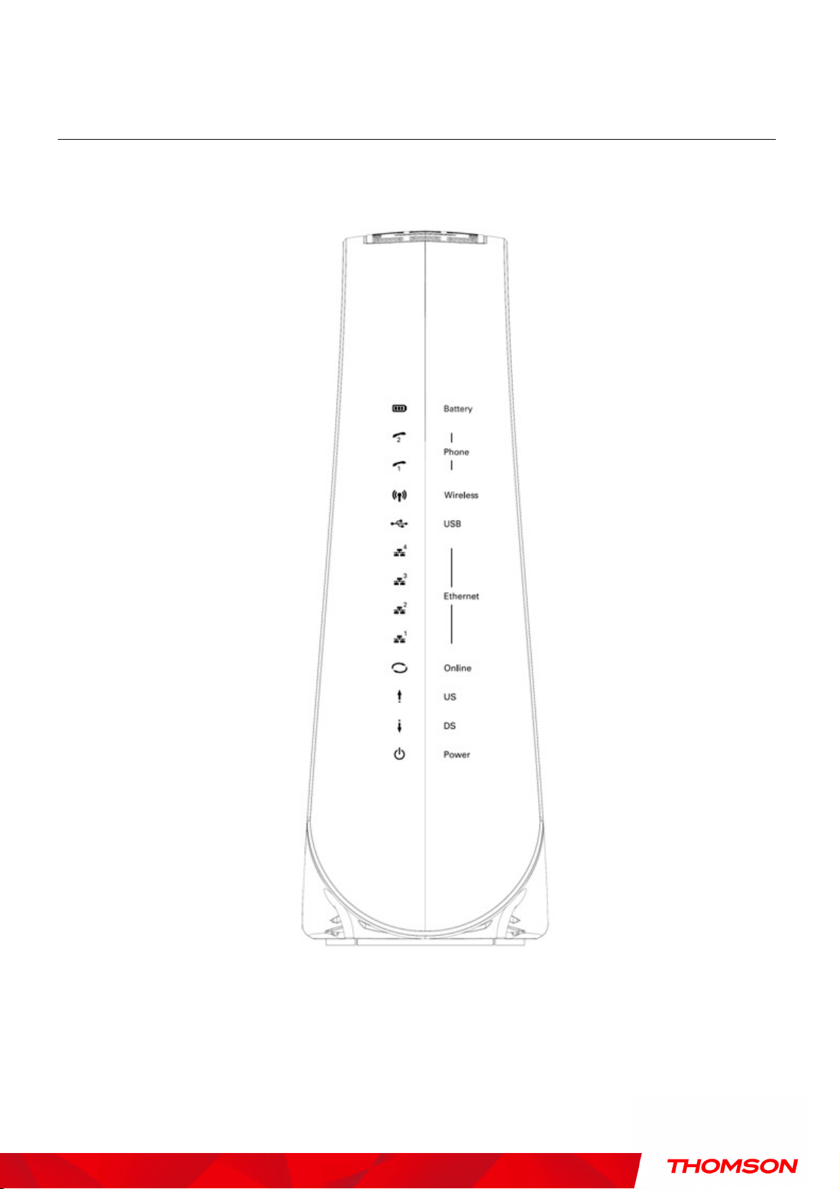
Wireless Voice Gateway Overview
Front Panel
The following illustration shows the front panel of the Wireless Voice Gateway:
8
Illustrations contained in this document are for representation only.
Page 13

Chapter 1: Connections and Setup
On 0.25 second
up
completed
During DHCP, configuration file
The LEDs on the front panel are described in the table below (from left to right):
DWG875 /
DWG875T
Boot-up
Operation
DOCSIS Start-
Power
ON ON ON ON
ON FLASH FLASH FLASH X X X X X X X X X
ON
ON FLASH OFF OFF X X X X X X X X X
ON ON FLASH OFF X X X X X X X X X
Internet Ethernet
DS US Online 1 2 3 4
ON ON ON ON On X ON ON X
ON ON ON
1 second
X X X X X X X X X
USB Wireless Tel 1 Tel 2 Battery
Description
Power on 0.25 sec
From power ON to system
initialization complete
Following system initialization
complete to (before)
During DS scanning and
acquiring SYNC
From SYNC completed,
receiving UCD to ranging
Operation
Channel
Bonding
Operation
ON ON ON FLASH X X X X X X X X X
ON ON ON ON X X X X X X X X X Operational (NACO=ON)
ON FLASH FLASH OFF X X X X X X X X X Operational (NACO=OFF)
FLASH FLASH FLASH FLASH FLASH X X X X X X X X
X X X X OFF X X X X X
OFF X X X X X X X X X
X X X
X X X
download, registration, and
Baseline Privacy initialization
Wait registration with all DS
and all US – Lights Flash
sequentially from the right to
left
From 1 to 4 DS, from 1 to 4
LEDs are ON.
From 5 to 8 DS, From 1 to 4
LEDs are flashing
From 1 to 4 US, from 1 to 4
LEDs are ON.
Wait registration with all DS
FLASH FLASH FLASH FLASH FLASH X X X X X
9
X X X
Illustrations contained in this document are for representation only.
and all US – Lights Flash
sequentially from the left to
right
Page 14

Chapter 1: Connections and Setup
ON ON ON ON X X X X X X OFF FLASH
OFF MTA SNMP/TFTP
ON ON ON ON X X X X X X FLASH
FLASH
OFF RSIP for NCS/Register for SIP
OFF OFF OFF OFF
No Ethernet Link
ON ON ON ON Ethernet Link
OFF
Wireless is disable
FLASH
TX/RX Wireless Traffic
OFF
No USB Link
ON USB Link
ON ON
Both Lines On
-
Hook
FLASH
ON
Tel1 Off
-
hook, Tel2 On
-
hook
ON FLASH
Tel1 On
-
hook, Tel2 Off
-
hook
FLASH
FLASH
Both Lines Off
-
Hook
ON ON
Both Lines On
-
Hook
FLASH
ON
Tel1 Off
-
hook, Tel2 On
-
hook
ON FLASH
Tel1 On
-
hook, Tel2 Off
-
hook
FLASH
FLASH
Both Lines Off
-
Hook
ON ON
Both Lines On
-
Hook
FLASH
ON
Tel1 Off
-
hook, Tel2 On
-
hook
ON FLASH
Tel1 On
-
hook, Tel2 Off
-
hook
FLASH
FLASH
Both Lines Off
-
Hook
ON
Both Lines On
-
Hook
FLASH
Tel1 Off
-
hook, Tel2
On-
hook
ON Tel1 On
-
hook, Tel2 Off
-
hook
FLASH
Both Lines Off
-
Hook
ON
Both Lines On
-
Hook
FLASH
Tel1 Off
-
hook, Tel2 On
-
hook
ON Tel1 On
-
hook, Tel2 Off
-
hook
FLASH
Both Lines Off
-
Hook
Both Lines On
-
Hook
Tel1 Off
-
hook, Tel2 On
-
hook
Tel1 On
-
hook, Tel2 Off
-
hook
Both Lines Off
-
Hook
DWG875 /
DWG875T
MTA
initialization
CPE Operation
USB Operation
AC Good
Battery Good
AC Good
Battery Low
Internet Ethernet
Power
DS US Online 1 2 3 4
ON ON ON ON X X X X X X FLASH OFF OFF MTA DHCP
ON X X X
FLASH FLASH FLASH FLASH
ON X X X X X X X X
ON X X X X X X X
On < CM Normal Operation >
On < CM Normal Operation >
USB Wireless Tel 1 Tel 2 Battery
X X X X X
ON Wireless initiate success or
X X X X
FLASH
<CM
Normal
Operatio
X X X
ON
FLASH
Description
TX/RX Ethernet Traffic
TX/RX USB Traffic
AC Good
Battery Bad
AC Fail
Battery Good
AC Fail
Battery Low
AC Fail
Battery Bad
SW Download
Operation
n>
Flash
Flash
ON FLASH FLASH ON X X X X X X X X X
< CM Normal Operation >
Off Off
< All LEDs may be unlit due to lack of battery power> OFF
Off
OFF
OFF
FLASH
A software download and
while updating the FLASH
memory
10
Illustrations contained in this document are for representation only.
Page 15
Chapter 1: Connections and Setup
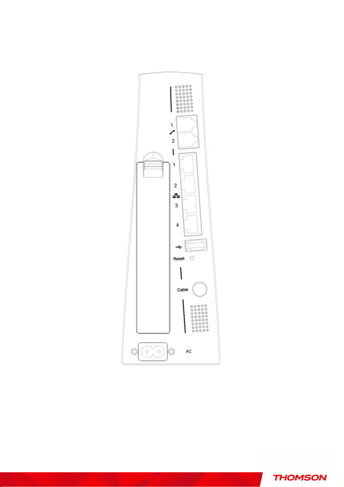
Rear Panel
A TEL1 & TEL2 2x Telephony RJ-11 connectors
B ETHERNET 1 2 3 4: 4x Ethernet 10/100/1000 Mbps RJ-45 connectors
C USB Host: 1x USB 2.0 Connector
D Reset: 1x Reset or reset to factory default this Wireless Voice Gateway
11
Illustrations contained in this document are for representation only.
Page 16

Chapter 1: Connections and Setup
E CABLE: 1x F-Connector for the coax cable
F Power Connector: 1x AC
I WPS & WiFi on/off button: 1x button with two features:
to activate/disable the WiFi, to execute a WPS association
Power Connector
12
Illustrations contained in this document are for representation only.
Page 17

Chapter 1: Connections and Setup
Relationship among the Devices
This illustration shows a cable company that offers DOCSIS and PacketCable-compliant voice/data
services.
What the Modem Does
The Wireless Voice Gateway provides high-speed Internet access as well as cost-effective, toll-quality
telephone voice and fax/modem services over residential, commercial, and education subscribers on
public and private networks via an existing CATV infrastructure. It can inter-operate with the
PacketCable compliant head-end equipment and provide the IP-based voice communications. The IP
traffic can transfer between the Wireless Voice Gateway and DOCSIS compliant head-end equipment.
The data security secures upstream and downstream communications.
13
Illustrations contained in this document are for representation only.
Page 18

Chapter 1: Connections and Setup
What the Modem Needs to Do Its Job
The Right Cable Company:
Make sure your local cable company provides data services that
use cable TV industry-standard DOCSIS compliant and PacketCable compliant technology.
The Internet/Telephony Service Provider (ISP/TSP):
Your cable company provides you
access to an Internet Service Provider (ISP) and Telephony Service Provider (TSP). The ISP is
your gateway to the Internet and provides you with a pipeline to access Internet content on the
World Wide Web (WWW). The TSP provides you with telephony access to other modems or
other telephony services over the Public Switched Telephone Network (PSTN).
Check with your cable company to make sure you have everything you need to begin; they’ll know if
you need to install special software or re-configure your computer to make your cable internet service
work for you.
14
Illustrations contained in this document are for representation only.
Page 19

Chapter 1: Connections and Setup
Contact Your Local Cable Company
You will need to contact your cable company to establish an Internet account before you can use your
gateway. You should have the following information ready (which you will find on the sticker on the
gateway):
• The serial number
• The model number
• The Cable Modem (CM) Media Access Control (MAC) address
• The Terminal Adapter (EMTA) MAC address
• Security information: Service Set IDentifier (SSID), Encryption key / passphrase (WPA2-PSK
by default), channel number. Default values are indicated underneath the modem on the sticker.
Please verify the following with the cable company
The cable service to your home supports DOCSIS compliant two-way modem access.
Your internet account has been set up. (The Media Terminal Adapter will provide data service if
the cable account is set up but no telephony service is available.)
You have a cable outlet near your PC and it is ready for Cable Modem service.
Note: It is important to supply power to the modem at all times. Keeping your modem plugged in will
keep it connected to the Internet. This means that it will always be ready whenever you need.
Important Information
Your cable company should always be consulted before installing a new cable outlet. Do not attempt any
rewiring without contacting your cable company first.
15
Illustrations contained in this document are for representation only.
Page 20

Chapter 1: Connections and Setup
Connecting the Wireless Voice Gateway to a Single Computer
This section of the manual explains how to connect your Wireless Voice Gateway to the USB or Ethernet
port on your computer and install the necessary software. Please refer to Figure 1 to help you connect
your Digital Cable Modem for the best possible connection.
Attaching the Cable TV Wire to the Wireless Voice Gateway
1. Locate the Cable TV wire. You may find it one of three ways:
a. Connected directly to a TV, a Cable TV converter box, or VCR. The line will be connected to
the jack, which should be labeled either IN, CABLE IN, CATV, CATV IN, etc.
b. Connected to a wall-mounted cable outlet.
c. Coming out from under a baseboard heater or other location. See Figure 1 for the wiring
example.
Notes: For optimum performance, be sure to
connect your Wireless Voice Gateway to the first
point the cable enters your home. The splitter
must be rated for at least 1GHz.
Fig. 1: Basic Home Wiring
16
Illustrations contained in this document are for representation only.
Page 21

Chapter 1: Connections and Setup
Important Connection Information
The Wireless Voice Gateway supports Ethernet connection.
Below are important points to remember before you connect the Wireless Voice Gateway.
For Ethernet connections, go to page 21.
For telephone and fax connections, go to page 23.
If you do not want to use the CD-ROM, follow instructions 1 through 4 to connect the Wireless Voice
Gateway to the Ethernet port on your computer. Instructions must be followed in the order they
appear.
1. Connect one end of the coaxial cable to the cable connection on the wall, and the other end to the
CABLE jack on the Wireless Voice Gateway.
2. Attaching power cord to Wireless Voice Gateway and plug into the AC outlet.
3. Insert the supplied Wireless Voice Gateway CD-ROM. Wait momentarily for the CD window display.
DWG875/DWG875T
Fig. 2: Main screen of CD
4. Close all open applications and dialog boxes, including the CD window.
Note: Some applications may interfere with your Wireless Voice Gateway installation.
17
Illustrations contained in this document are for representation only.
Page 22

Chapter 1: Connections and Setup
Ethernet Connection to a Computer
Make the connection to the modem in the following sequence:
1. Connect one end of the coaxial cable to the cable connection on the wall, and the other end to the
CABLE jack on the Wireless Voice Gateway.
2. Connect the plug from the AC power supply into the POWER AC ADAPTER jack on the Wireless
Voice Gateway, and plug the power supply into an AC outlet.
Note: Use only the power supply that accompanied this unit. Using other adapters may damage the unit.
3. Connect one end of the Ethernet cable to an Ethernet port on the back of your computer, and the
other end to the ETHERNET port on the Wireless Voice Gateway.
Fig.3: Ethernet Connection
18
Illustrations contained in this document are for representation only.
Page 23

Chapter 1: Connections and Setup
Connecting More Than A Computer to the Wireless Voice Gateway
If you need to connect more than one computer to the Wireless Voice Gateway, simply connect the
computers to an Ethernet port on the rear panel.
Fig.4: Multiple-PC Connection
Note: You may need to check with your service provider in order to connect multiple computers.
19
Illustrations contained in this document are for representation only.
Page 24

Chapter 1: Connections and Setup
Telephone or Fax Connection
When properly connected, most telephony devices can be used with the Wireless Voice Gateway just as
with a conventional telephone service. To make a normal telephone call, pick up the handset; listen for a
dial tone, then dial the desired number. For services such as call waiting, use the hook switch (or FLASH
button) to change calls. The following procedures describe some of the possible connection schemes for
using telephony devices with the Wireless Voice Gateway.
1. Connect a standard phone line cord directly from the phone (fax machine, answering machine, caller
ID box, etc.) to one of the LINE jacks on the Wireless Voice Gateway.
2. If there is a phone line in your home which is NOT connected to another telephone service provider,
connect a standard phone line cord from a jack on this line to one of the LINE jacks of the Wireless
Voice Gateway. Connect a standard phone line cord directly from the phone (fax machine, answering
machine, caller ID box, etc.) to one of the other jacks in the house that uses that line.
3. If you have a multi-line telephone, connect a standard phone line cord (not an RJ-14 type line cord)
from the phone to the LINE jacks on the Wireless Voice Gateway. (Other phones can be added to
each line by using standard phone line splitters.
Fig. 5: Phone/Fax Connection
20
Illustrations contained in this document are for representation only.
Page 25

Chapter 1: Connections and Setup
Turning on the Wireless Voice Gateway
After installing the Wireless Voice Gateway and turn it on for the first time (and each time the modem is
reconnected to the power), it goes through several steps before it can be used. Each of these steps is
represented by a different pattern of flashing lights on the front of the modem.
Note: All indicators flash once before the initialization sequence.
If both DS and US LEDs are flashing sequentially, it means the Wireless Voice Gateway is automatically
updating its system software. Please wait for the lights to stop flashing. You cannot use your modem
during this time. Do not remove the power supply, switch off (on/off switch) or reset the Wireless Voice
Gateway during this process.
21
Illustrations contained in this document are for representation only.
Page 26

Chapter 2: WEB Configuration
Chapter 2: WEB Configuration
To make sure that you can access the Internet successfully, please check the following first.
1. Make sure the connection (through Ethernet or USB) between the Wireless Voice Gateway and
your computer is OK.
2. Make sure the TCP/IP protocol is set properly.
3. Subscribe to a Cable Company.
4. Make sure appropriate LEDs are turned on for normal operation as noted in the previous
chapter.
Accessing the Web Configuration
The Wireless Voice Gateway offers local management capability through a built in HTTP server and
a number of diagnostic and configuration web pages. You can configure the settings on the web page
and apply them to the device.
Once your host PC is properly configured; please proceed as follows:
1. Start your web browser and type the private IP address of the Wireless Voice Gateway on the
URL field: 192.168.0.1.
2. After connecting to the device, you will be prompted to enter username and password. By
default, the username is “ ” (empty) and the password is “admin”.
Fig. 6 Dialogue for Login
If you login successfully, the main page will appear.
Please Note; some of the WEB pages shown later, will differ for different software versions and per service providers instructions.
Illustrations contained in this document are for representation only.
22
Page 27

Chapter 2: WEB Configuration
Outline of Web Manager
The main screen will be shown as below.
Fig. 7 Outline of Web Manager
Main Menu: the hyperlinks on the top of the page, including Gateway, VoIP and several
sub-menu items
Title: the sidebar on the left side of the page indicates the title of this management interface, e.g.,
Software in this example
Main Window: the current workspace of the web management, containing configuration or
status information
For easy navigation, the pages are organized in groups with group in names main menu. Individual
page names within each group are provided in the sidebar. So to navigate to a page, click the group
hyperlink at the top, then the page title on the sidebar.
Your cable company may not support the reporting of some items of information listed on your
gateway’s internal web pages. In such cases, the information field appears blank. This is normal.
23
Illustrations contained in this document are for representation only.
Page 28

Chapter 2: WEB Configuration
Warning message to change the password
At your first connection or while the password is the default one, a warning message is displayed on
the top banner of each Web configuration page. We want to encourage you to change the password in
order to enforce the security of your modem. Please refer to the chapter “
information.
Password
” page 27 for more
24
Illustrations contained in this document are for representation only.
Page 29

Chapter 2: WEB Configuration
Gateway – Status Web Page Group
1. Software
The information section shows the hardware and software information about your gateway.
The status section of this page shows how long your gateway has operated since last time being
powered up, and some key information the Cable Modem received during the initialization process
with your cable company. If Network Access shows “Allowed,” then your cable company has
configured your gateway to have Internet connectivity. If not, you may not have Internet access, and
should contact your cable company to resolve this.
Fig. 8 Gateway\Status\Software
25
Illustrations contained in this document are for representation only.
Page 30

Chapter 2: WEB Configuration
2. Connection
This page reports current connection status containing startup procedures, downstream and upstream
status, CM online information, and so on. The information can be useful to your cable company’s
support technician if you’re having problems.
Fig. 9 Gateway\Status\Connection
26
Illustrations contained in this document are for representation only.
Page 31

Chapter 2: WEB Configuration
3. Password
Forcing end user to change the password
Upon access to the web pages on the CPE side of the router, if the user has not changed the default
web password, a warning message must be displayed in the top banner of the web interface such as
being visible while accessing any tabs.
This warning message informs the user that the default password must be changed:
In the second sentence, “here” is a hyperlink to the password setting page. Clicking on “here” lead to
the display of the password setting page.
More information
By default, the username is empty (“”) and the password is “admin”.
This is set by different actions (non exhaustive list):
- at the manufactory level,
- following a reset factory on the modem,
- following a reset from the operator,
- following a change by the user who wants to come back to the default setting after using its own
settings
When the current password is the default one, the user is strongly encouraged to change the default
web password:
- Once the user logs in the web pages, the password setting page is displayed
- the warning message must be displayed in the top banner of the web interface
- The user can still access to all the web pages even if the password is not changed
- The warning message must be displayed on the top banner of each accessed Web page while the
password is not changed
- The password warning message must be visible while accessing all tabs in a the same web page
- The password warning message is no more displayed on the banners once the default
password has been replaced by a new one.
At your first connection or while the password is the default one, a warning message is displayed on
the top banner of each Web configuration page. We want to encourage you to change the password in
order to enforce the security of your modem.
27
Illustrations contained in this document are for representation only.
Page 32

Chapter 2: WEB Configuration
The password can be a maximum of 8 characters and is case sensitive. In addition, this page can be
used to restore the gateway to its original factory settings. Use this with caution, as all the settings you
have made will be lost. To perform this reset, set Restore Factory Defaults to Yes and click Apply.
This has the same effect as a factory reset using the rear panel reset switch, where you hold on the
switch for 15 seconds, then release it.
Note: We are always suggesting to modify the password is implementing for Voice Wireless Gateway.
It is a basically protection to access Voice Wireless Gateway.
Fig. 10 Gateway\Status\Password
To change the password: type the password, and re-enter it again.
If the password is accepted, you are required to re log on the web pages:
28
Illustrations contained in this document are for representation only.
Page 33

Chapter 2: WEB Configuration
If the password is not accepted, an error message is displayed:
Click on try again.
29
Illustrations contained in this document are for representation only.
Page 34

Chapter 2: WEB Configuration
4. Diagnostics
This page offers basic diagnostic tools for you to utilize when connectivity problems occur. When you
ping an Internet device, you send a packet to its TCP/IP stack, and it sends one back to yours. To use
the ping Test, enter the information needed and press Start Test; the Result will be displayed in the
lower part of the window. Press Abort Test to stop, and Clear Results to clear the result contents.
Note: Firewalls may cause pings to fail but still provide you TCP/IP access to selected devices behind
them. Keep this in mind when pinging a device that may be behind a firewall. Ping is most useful to
verify connectivity with PCs which do not have firewalls, such as the PCs on your LAN side.
Fig. 11 Gateway\Status\Diagnostics
30
Illustrations contained in this document are for representation only.
Page 35

Chapter 2: WEB Configuration
5. Event Log
This page displays the contents of the SNMP event log. Press “Clear Log” button to clear the logs.
Fig. 12 Gateway\Status\Event Log
31
Illustrations contained in this document are for representation only.
Page 36

Chapter 2: WEB Configuration
6. Backup/Restore
Backup/Restore Settings : This page allows you to save your current settings locally on your PC, or
to restore settings saved previously. The file name is “GatewaySettings.bin”.
Fig 13 Gateway\Status\Backup/Restore
32
Illustrations contained in this document are for representation only.
Page 37

Chapter 2: WEB Configuration
Gateway – Network Web Page Group
1. LAN
You can activate the DHCP server function for the LAN on this page.
With this activated function,
• your cable company’s DHCP server provides one IP address for your gateway,
• and your gateway’s DHCP server provides IP addresses, starting at the address you set in IP
Address on the LAN page, to your PCs. A DHCP server leases an IP address with an expiration
time.
To change the lowest IP address that your gateway will issue to your PCs, enter it into the IP Address
box and then click Apply.
IP Address and Subnet Mask:
A private IP address and Subnet Mask for LAN sub netting.
For example 192.168.0.1./ 255.255.255.0.
DHCP Server:
Select the check point of “Yes” or “No” to enable or disable a simple DHCP server for LAN.
Configure the IP address numbers for the DHCP server with “lease pool start” and “lease
pool end”.
Configure the IP address lease time with “lease time” for DHCP server. Default value is
604800 seconds.
Fig. 14 Gateway\Network\LAN
33
Illustrations contained in this document are for representation only.
Page 38

Chapter 2: WEB Configuration
2. WAN
You can configure the optional internal DHCP server for the WAN on this page. This can be required
by some ISP providers.
Select different WAN Connection Type will lead to different contents. Take the WAN connection
type-DHCP for example, you can release and renew the WAN lease by pressing the buttons.
You can enter a spoofed MAC address that causes your gateway networking stack to use that MAC
address when communicating instead of the usual WAN MAC address, e.g., if the MAC address is
00:11:e3:df:66:95, this spoofed MAC address could be 00:11:e3:df:66:97 or any desired MAC
address.
Fig. 15 Gateway\Network\WAN
34
Illustrations contained in this document are for representation only.
Page 39

Chapter 2: WEB Configuration
3. Computers
This page displays the status of the DHCP clients and current system time. You can cancel an IP
address lease by selecting it in the DHCP Client Lease Info list and then clicking the Force Available
button. If you do so, you may have to perform a DHCP Renew on that PC, so that it can obtain a new
lease.
Fig. 16 Gateway\Network\Computers
35
Illustrations contained in this document are for representation only.
Page 40

Chapter 2: WEB Configuration
4. DDNS - Dynamic DNS service
This page allows to setup for Dynamic DNS server.
Fig 17 Gateway\Network\DDNS
36
Illustrations contained in this document are for representation only.
Page 41

Chapter 2: WEB Configuration
5. Time server
This page allows configuration and display of the system time obtained from network servers via
Simple Network Time Protocol. The system has to be reset for any changes to take effect.
Fig 18
Gateway\Network\Time
37
Illustrations contained in this document are for representation only.
Page 42

Chapter 2: WEB Configuration
Gateway – Advanced Web Page Group
1. Options
This page allows you to enable/disable some features of the Wireless Voice Gateway.
Fig. 19 Gateway\Advanced\Options
WAN Blocking prevents others on the WAN side from being able to ping your gateway. With
WAN Blocking enabled, your gateway will not respond to pings it receives, effectively “hiding”
your gateway.
Ipsec PassThrough enables IpSec type packets to pass WAN LAN. IpSec (IP Security) is a
security mechanism used in Virtual Private Networks (VPNs).
PPTP PassThrough enables PPTP type packets to pass WAN LAN. PPTP (Point to Point
Tunneling Protocol) is another mechanism sometimes used in VPNs.
Remote Config Management makes the configuration web pages in your gateway accessible
from the WAN side. Note that page access is limited to only those who know the gateway access
password. When accessing your gateway from a remote location, your must use HTTP port 8080
and the WAN IP address of the gateway. For example, if the WAN IP address is 157.254.5.7, you
would navigate to http://157.254.5.7:8080 to reach your gateway.
Multicast Enable enables multicast traffic to pass WAN LAN. You may need to enable this to
see some types of broadcast streaming and content on the Internet.
UPnP Universal Plug and Play (UPnP) helps devices, such as Internet appliances and computers,
access the network and connect to other devices as needed. UPnP devices can automatically
38
Illustrations contained in this document are for representation only.
Page 43

Chapter 2: WEB Configuration
discover the services from other registered UPnP devices on the network.
NatSipAlg Enable the gateway implements
default and help in solving NAT related problems in client LAN side
SIP ALG (Application-level gateway). It is
enabled by
.
39
Illustrations contained in this document are for representation only.
Page 44

Chapter 2: WEB Configuration
2. IP Filtering
This page enables you to enter the IP address ranges of PCs on your LAN that you don’t want to have outbound
access to the WAN. These PCs can still communicate with each other on your LAN, but packets designated to WAN
addresses are blocked by the gateway.
Fig. 20 Gateway\Advanced\IP Filtering
40
Illustrations contained in this document are for representation only.
Page 45

Chapter 2: WEB Configuration
3. MAC Filtering
This page enables you to enter the MAC address of specific PCs on your LAN that you do not wish to
have outbound access to the WAN. As with IP filtering, these PCs can still communicate with each
other through the gateway, but packets they send to WAN addresses are blocked.
Fig. 21 Gateway\Advanced\MAC Filtering
41
Illustrations contained in this document are for representation only.
Page 46

Chapter 2: WEB Configuration
4. Port Filtering
This page allows you to enter ranges of destination ports (applications) that you don’t want your LAN
PCs to send packets to. Any packets your LAN PCs send to these destination ports will be blocked.
For example, you could block access to worldwide web browsing (http = port 80) but still allow email
service (SMTP port 25 and POP-3 port 110). To enable port filtering, set Start Port and End Port for
each range, and click Apply. To block only one port, set both Start and End ports with the same value.
Fig. 22 Gateway\Advanced\Port Filtering
42
Illustrations contained in this document are for representation only.
Page 47

Chapter 2: WEB Configuration
5. Forwarding
For LAN WAN communications, the gateway normally only allows you to originate an IP
connection with a PC on the WAN; it will ignore attempts of the WAN PC to originate a connection
onto your PC. This protects you from malicious attacks from outsiders. However, sometimes you may
wish for anyone outside to be able to originate a connection to a particular PC on your LAN if the
destination port (application) matches one you specify.
This page allows you to specify up to 10 such rules. For example, to specify that outsiders should have
access to an FTP server you have running at 192.168.0.5, create a rule with that address and Start Port
=20 and End Port =21 (FTP port ranges) and Protocol = TCP (FTP runs over TCP and the other
transport protocol, UDP), and click Apply. This will cause inbound packets that match to be forwarded
to that PC rather than blocked. As these connections are not tracked, no entry is made for them in the
Connection Table. The same IP address can be entered multiple times with different ports.
Fig. 23 Gateway\Advanced\Forwarding
43
Illustrations contained in this document are for representation only.
Page 48

Chapter 2: WEB Configuration
6. Port Triggers
Some Internet activities, such as interactive gaming, require that a PC on the WAN side of your
gateway be able to originate connections during the game with your game playing PC on the LAN side.
You could use the Advanced-Forwarding web page to construct a forwarding rule during the game,
and then remove it afterwards (to restore full protection to your LAN PC) to facilitate this. Port
triggering is an elegant mechanism that does this work for you, each time you play the game.
Fig. 24 Gateway\Advanced\Port Triggers
Port Triggering works as follows. Imagine you want to play a particular game with PCs somewhere on
the Internet. You make one time effort to set up a Port Trigger for that game, by entering into Trigger
Range the range of destination ports your game will be sending to, and entering into Target Range
the range of destination ports the other player (on the WAN side) will be sending to (ports your PC’s
game receives on). Application programs like games publish this information in user manuals. Later,
each time you play the game, the gateway automatically creates the forwarding rule necessary. This
rule is valid until 10 minutes after it sees game activity stop. After 10 minutes, the rule becomes
inactive until the next matched outgoing traffic arrives.
For example, suppose you specify Trigger Range from 6660 to 6670 and Target Range from 113 to
113. An outbound packet arrives at the gateway with your game-playing PC source IP address
192.168.0.10, destination port 666 over TCP/IP. This destination port is within the Trigger destined for
port 113 to your game-playing PC at 192.168.0.10.
You can specify up to 10 port ranges on which to trigger.
44
Illustrations contained in this document are for representation only.
Page 49

Chapter 2: WEB Configuration
7. DMZ Host
Use this page to designate one PC on your LAN that should be left accessible to all PCs from the
WAN side, for all ports. For example, if you put an HTTP server on this machine, anyone will be able
to access that HTTP server by using your gateway IP address as the destination. A setting of “0”
indicates NO DMZ PC. “Host” is another Internet term for a PC connected to the Internet.
Fig. 25 Gateway\Advanced\DMZ Host
45
Illustrations contained in this document are for representation only.
 Loading...